1
OmniLab ConnectINSTRUCTIONS FOR USE
Intended Use
The OmniLab Connect connects a Philips Respironics Sleep or Ventilation Device to a non-Philips Respironics polysomnograph (PSG) device. The OmniLab Connect translates proprietary Philips Respironics digital signals into analog output signals for the non-Philips Respironics PSG system.
OmniLab Connect is intended for use in a clinical setting.
Caution! US Federal law restricts this device to sale by or on the order of a physician.
Warnings • Before each use, inspect the device, power cord, and all cables for any damage. Replace any damaged parts, cables, or cords
before use.• Do not use the OmniLab Connect or associated system equipment with multiple portable socket outlets or extension cords.• Do not connect sensors directly to the OmniLab Connect.• Do not connect equipment that is not specified for use with this system.• Route all cables safely so that they cannot be tripped over or damaged.• Do not place fluids near the device or immerse the device in fluids. In case of accidental exposure to fluids, unplug the
OmniLab Connect device and return to Philips Respironics for servicing.• Use of this equipment adjacent to or stacked with other equipment should be avoided because it could result in improper
operation. If such use is necessary, this equipment and the other equipment should be observed to verify that they are operating normally.
• To ensure that this equipment delivers safe, effective therapy, use only Philips Respironics accessories. The use of accessories, transducers, and cables other than those specified by Philips Respironics may result in increased emissions or decreased immunity of the device.
• Portable and Mobile RF Communications Equipment can affect Medical Electrical Equipment. See the EMC section of this manual for distances to observe between RF Generators and the ventilator to avoid interference.
• Do not use this device near active high frequency surgical equipment and the Radio Frequency shielded room of a Medical Electrical system for magnetic resonance imaging, where the intensity of electromagnetic disturbances is high.
Cautions• Do not attempt to repair the device. Repairs and modifications must be performed by Philips Respironics-authorized service personnel only. • When positioning the OmniLab Connect, ensure that the power cable is accessible because removing power is the only way to
turn off the device.• Use only with UL 60950-1, IEC 60950-1, EN 60950-1, or CSA C22.2#60950-1 certified IT equipment.• This medical electrical equipment has special needs regarding EMC and must be installed in accordance with the EMC
information in this manual.Note: Any serious incident that has occurred in relation to this device should be reported to Philips and the competent authority of the Member State in which the user and/or patient is established.
Package Contents
• OmniLab Connect • Velcro® Pieces • Power Cord• Instructions for Use • Rubber Feet
2
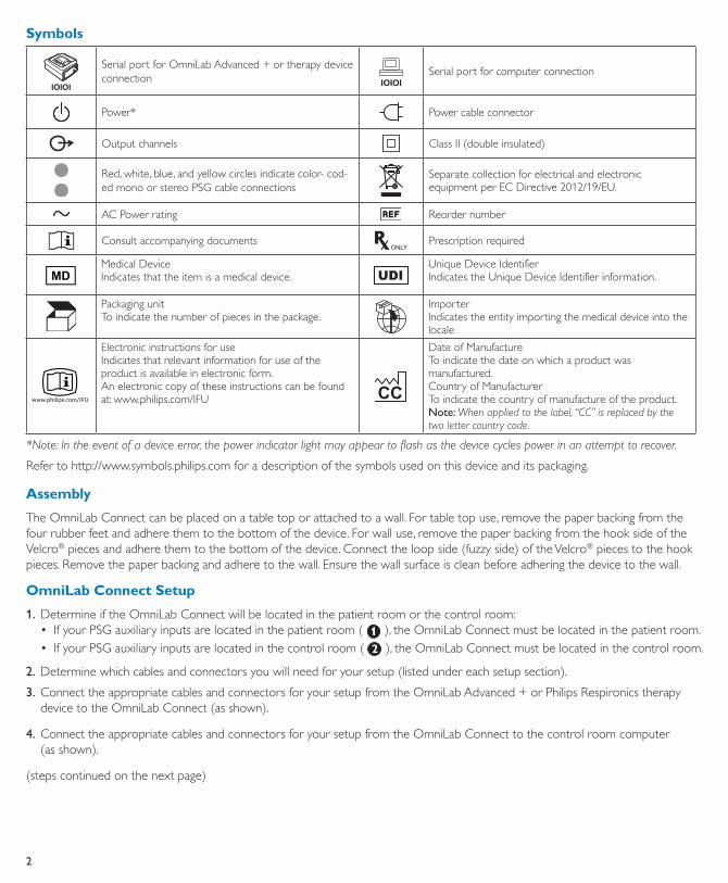
Symbols
Serial port for OmniLab Advanced + or therapy device connection
Serial port for computer connection
Power* Power cable connector
Output channels Class II (double insulated)
Red, white, blue, and yellow circles indicate color- cod-ed mono or stereo PSG cable connections
Separate collection for electrical and electronic equipment per EC Directive 2012/19/EU.
AC Power rating Reorder number
Consult accompanying documents Prescription required
MDMedical DeviceIndicates that the item is a medical device. UDI
Unique Device IdentifierIndicates the Unique Device Identifier information.
Packaging unitTo indicate the number of pieces in the package.
ImporterIndicates the entity importing the medical device into the locale
www.philips.com/IFU
Electronic instructions for useIndicates that relevant information for use of the product is available in electronic form.An electronic copy of these instructions can be found at: www.philips.com/IFU CC
Date of ManufactureTo indicate the date on which a product was manufactured.Country of ManufacturerTo indicate the country of manufacture of the product.Note: When applied to the label, “CC” is replaced by the two letter country code.
*Note: In the event of a device error, the power indicator light may appear to flash as the device cycles power in an attempt to recover.
Refer to http://www.symbols.philips.com for a description of the symbols used on this device and its packaging.
Assembly
The OmniLab Connect can be placed on a table top or attached to a wall. For table top use, remove the paper backing from the four rubber feet and adhere them to the bottom of the device. For wall use, remove the paper backing from the hook side of the Velcro® pieces and adhere them to the bottom of the device. Connect the loop side (fuzzy side) of the Velcro® pieces to the hook pieces. Remove the paper backing and adhere to the wall. Ensure the wall surface is clean before adhering the device to the wall.
OmniLab Connect Setup
1. Determine if the OmniLab Connect will be located in the patient room or the control room:• If your PSG auxiliary inputs are located in the patient room ( ), the OmniLab Connect must be located in the patient room.• If your PSG auxiliary inputs are located in the control room ( ), the OmniLab Connect must be located in the control room.
2. Determine which cables and connectors you will need for your setup (listed under each setup section).
3. Connect the appropriate cables and connectors for your setup from the OmniLab Advanced + or Philips Respironics therapy device to the OmniLab Connect (as shown).
4. Connect the appropriate cables and connectors for your setup from the OmniLab Connect to the control room computer (as shown).
(steps continued on the next page)
3
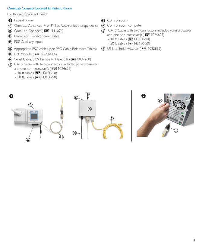
OmniLab Connect Located in Patient Room
For this setup, you will need:
Patient room Control room OmniLab Advanced + or Philips Respironics therapy device Control room computer
OmniLab Connect ( 1111076) CAT5 Cable with two connectors included (one crossover and one non-crossover): ( 1024625) - 10 ft cable ( H3150-10) - 50 ft cable ( H3150-50)
OmniLab Connect power cable
PSG Auxiliary Inputs
Appropriate PSG cables (see PSG Cable Reference Tables) USB to Serial Adapter ( 1022895)
Link Module ( 1061644A) Serial Cable, DB9 Female to Male, 6 ft ( 1037268) CAT5 Cable with two connectors included (one crossover
and one non-crossover): ( 1024625) - 10 ft cable ( H3150-10) - 50 ft cable ( H3150-50)
4
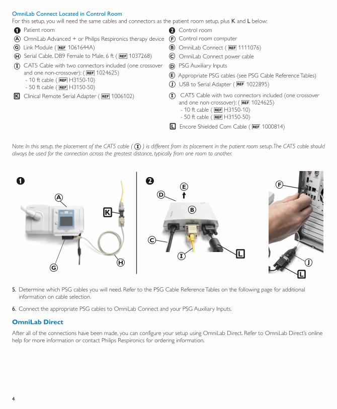
OmniLab Connect Located in Control RoomFor this setup, you will need the same cables and connectors as the patient room setup, plus K and L below:
Patient room Control room OmniLab Advanced + or Philips Respironics therapy device Control room computer
Link Module ( 1061644A) OmniLab Connect ( 1111076) Serial Cable, DB9 Female to Male, 6 ft ( 1037268) OmniLab Connect power cable
CAT5 Cable with two connectors included (one crossover and one non-crossover): ( 1024625) - 10 ft cable ( H3150-10) - 50 ft cable ( H3150-50)
PSG Auxiliary Inputs
Appropriate PSG cables (see PSG Cable Reference Tables)
USB to Serial Adapter ( 1022895)
Clinical Remote Serial Adapter ( 1006102) CAT5 Cable with two connectors included (one crossover and one non-crossover): ( 1024625) - 10 ft cable ( H3150-10) - 50 ft cable ( H3150-50)
Encore Shielded Com Cable ( 1000814)
Note: In this setup, the placement of the CAT5 cable ( ) is different from its placement in the patient room setup. The CAT5 cable should always be used for the connection across the greatest distance, typically from one room to another.
5. Determine which PSG cables you will need. Refer to the PSG Cable Reference Tables on the following page for additional information on cable selection.
6. Connect the appropriate PSG cables to OmniLab Connect and your PSG Auxiliary Inputs.
OmniLab Direct
After all of the connections have been made, you can configure your setup using OmniLab Direct. Refer to OmniLab Direct’s online help for more information or contact Philips Respironics for ordering information.
5
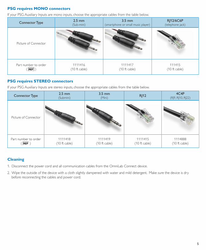
PSG requires MONO connectors
If your PSG Auxiliary Inputs are mono inputs, choose the appropriate cables from the table below.
Connector Type 2.5 mm(Sub-mini)
3.5 mm(smartphone or small music player)
RJ12/6C6P(telephone jack)
Picture of Connector
Part number to order( )
1111416(10 ft cable)
1111417(10 ft cable)
111415(10 ft cable)
PSG requires STEREO connectors
If your PSG Auxiliary Inputs are stereo inputs, choose the appropriate cables from the table below.
Connector Type 2.5 mm(Submini)
3.5 mm(Mini)
RJ12 4C4P(RJ9, RJ10, RJ22)
Picture of Connector
Part number to order( )
1111418(10 ft cable)
1111419(10 ft cable)
1111415(10 ft cable)
1114888(10 ft cable)
Cleaning
1. Disconnect the power cord and all communication cables from the OmniLab Connect device.
2. Wipe the outside of the device with a cloth slightly dampened with water and mild detergent. Make sure the device is dry before reconnecting the cables and power cord.
6
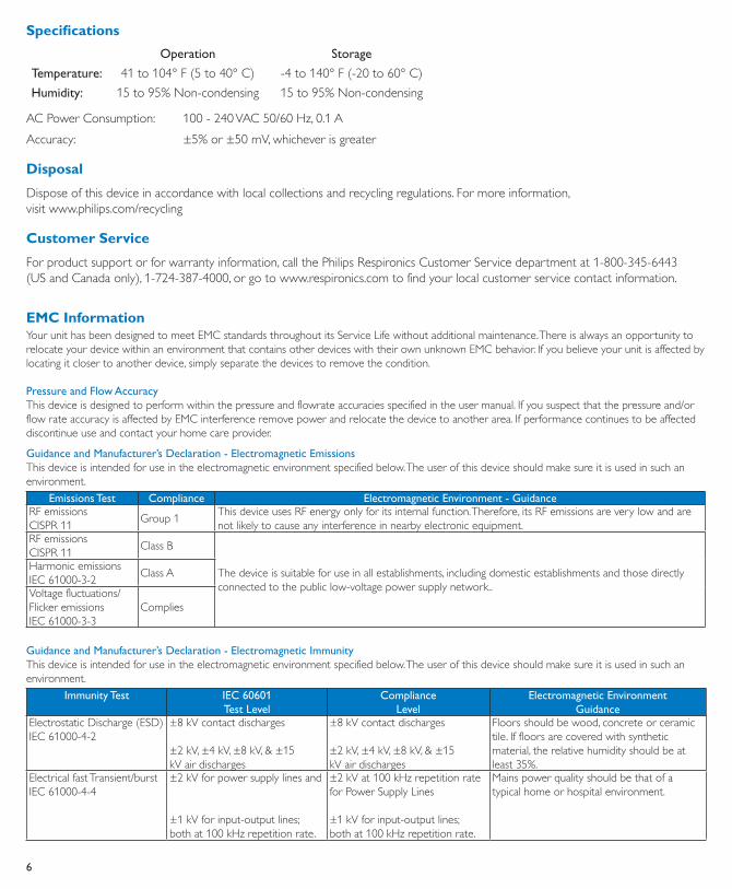
Specifications
Operation Storage
Temperature: 41 to 104° F (5 to 40° C) -4 to 140° F (-20 to 60° C)
Humidity: 15 to 95% Non-condensing 15 to 95% Non-condensing
AC Power Consumption: 100 - 240 VAC 50/60 Hz, 0.1 A
Accuracy: ±5% or ±50 mV, whichever is greater
Disposal
Dispose of this device in accordance with local collections and recycling regulations. For more information, visit www.philips.com/recycling
Customer Service
For product support or for warranty information, call the Philips Respironics Customer Service department at 1-800-345-6443 (US and Canada only), 1-724-387-4000, or go to www.respironics.com to find your local customer service contact information.
EMC InformationYour unit has been designed to meet EMC standards throughout its Service Life without additional maintenance. There is always an opportunity to relocate your device within an environment that contains other devices with their own unknown EMC behavior. If you believe your unit is affected by locating it closer to another device, simply separate the devices to remove the condition.
Pressure and Flow AccuracyThis device is designed to perform within the pressure and flowrate accuracies specified in the user manual. If you suspect that the pressure and/or flow rate accuracy is affected by EMC interference remove power and relocate the device to another area. If performance continues to be affected discontinue use and contact your home care provider.
Guidance and Manufacturer’s Declaration - Electromagnetic EmissionsThis device is intended for use in the electromagnetic environment specified below. The user of this device should make sure it is used in such an environment.
Emissions Test Compliance Electromagnetic Environment - GuidanceRF emissionsCISPR 11
Group 1This device uses RF energy only for its internal function. Therefore, its RF emissions are very low and are not likely to cause any interference in nearby electronic equipment.
RF emissionsCISPR 11
Class B
The device is suitable for use in all establishments, including domestic establishments and those directly connected to the public low-voltage power supply network..
Harmonic emissions IEC 61000-3-2
Class A
Voltage fluctuations/Flicker emissionsIEC 61000-3-3
Complies
Guidance and Manufacturer’s Declaration - Electromagnetic ImmunityThis device is intended for use in the electromagnetic environment specified below. The user of this device should make sure it is used in such an environment.
Immunity Test IEC 60601 Test Level
Compliance Level
Electromagnetic Environment Guidance
Electrostatic Discharge (ESD)IEC 61000-4-2
±8 kV contact discharges
±2 kV, ±4 kV, ±8 kV, & ±15kV air discharges
±8 kV contact discharges
±2 kV, ±4 kV, ±8 kV, & ±15kV air discharges
Floors should be wood, concrete or ceramic tile. If floors are covered with synthetic material, the relative humidity should be at least 35%.
Electrical fast Transient/burstIEC 61000-4-4
±2 kV for power supply lines and
±1 kV for input-output lines;both at 100 kHz repetition rate.
±2 kV at 100 kHz repetition rate for Power Supply Lines
±1 kV for input-output lines;both at 100 kHz repetition rate.
Mains power quality should be that of a typical home or hospital environment.
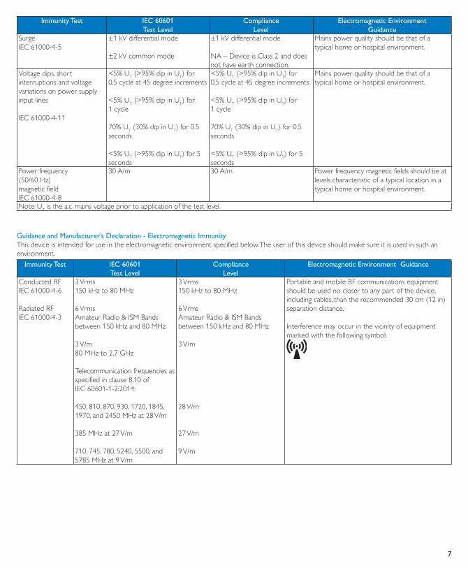
7
Immunity Test IEC 60601 Test Level
Compliance Level
Electromagnetic Environment Guidance
Surge IEC 61000-4-5
±1 kV differential mode
±2 kV common mode
±1 kV differential mode
NA – Device is Class 2 and does not have earth connection.
Mains power quality should be that of a typical home or hospital environment.
Voltage dips, short interruptions and voltage variations on power supply input lines
IEC 61000-4-11
<5% UT (>95% dip in UT) for0.5 cycle at 45 degree increments
<5% UT (>95% dip in UT) for1 cycle
70% UT (30% dip in UT) for 0.5 seconds
<5% UT (>95% dip in UT) for 5 seconds
<5% UT (>95% dip in UT) for0.5 cycle at 45 degree increments
<5% UT (>95% dip in UT) for1 cycle
70% UT (30% dip in UT) for 0.5 seconds
<5% UT (>95% dip in UT) for 5 seconds
Mains power quality should be that of a typical home or hospital environment.
Power frequency(50/60 Hz)magnetic fieldIEC 61000-4-8
30 A/m 30 A/m Power frequency magnetic fields should be at levels characteristic of a typical location in a typical home or hospital environment.
Note: UT is the a.c. mains voltage prior to application of the test level.
Guidance and Manufacturer’s Declaration - Electromagnetic ImmunityThis device is intended for use in the electromagnetic environment specified below. The user of this device should make sure it is used in such an environment.
Immunity Test IEC 60601Test Level
ComplianceLevel
Electromagnetic Environment Guidance
Conducted RFIEC 61000-4-6
Radiated RFIEC 61000-4-3
3 Vrms150 kHz to 80 MHz
6 VrmsAmateur Radio & ISM Bands between 150 kHz and 80 MHz
3 V/m80 MHz to 2.7 GHz
Telecommunication frequencies as specified in clause 8.10 ofIEC 60601-1-2:2014:
450, 810, 870, 930, 1720, 1845, 1970, and 2450 MHz at 28 V/m
385 MHz at 27 V/m
710, 745, 780, 5240, 5500, and 5785 MHz at 9 V/m
3 Vrms150 kHz to 80 MHz
6 VrmsAmateur Radio & ISM Bands between 150 kHz and 80 MHz
3 V/m
28 V/m
27 V/m
9 V/m
Portable and mobile RF communications equipment should be used no closer to any part of the device, including cables, than the recommended 30 cm (12 in) separation distance.
Interference may occur in the vicinity of equipment marked with the following symbol:

Philips Medical Systems Nederland B.V.Veenpluis 65684PC BestThe Netherlands
Respironics Inc.1001 Murry Ridge LaneMurrysville, PA 15668 USA
1112086
1112163 R05JDW 02/28/2020
Recommended