© 2015 Qualcomm Technologies, Inc. All rights reserved.
5G Waveform & Multiple Access Techniques
November 4, 2015
1

© 2015 Qualcomm Technologies, Inc. All rights reserved.
Outline
2
Executive summary
Waveform & multi-access techniques evaluations and recommendations
• Key waveform and multiple-access design targets
• Physical layer waveforms comparison
• Multiple access techniques comparison
• Recommendations
Additional information on physical layer waveforms
• Single carrier waveform
• Multi-carrier OFDM-based waveform
Additional information on multiple access techniques
• Orthogonal and non-orthogonal multiple access
Appendix
• References
• List of abbreviations

© 2015 Qualcomm Technologies, Inc. All rights reserved.3
Executive summary

© 2015 Qualcomm Technologies, Inc. All rights reserved.
Executive Summary
4
• 5G will support diverse use cases
- Enhanced mobile broadband, wide area IoT, and high-reliability services
• OFDM family is well suited for mobile broadband and beyond
- Efficient MIMO spatial multiplexing for higher spectral efficiency
- Scalable to wide bandwidth with lower complexity receivers
• CP-OFDM/OFDMA for 5G downlink
- CP-OFDM with windowing/filtering delivers higher spectral efficiency with comparable out-of-band emission
performance and lower complexity than alternative multi-carrier waveforms under realistic implementations
- Co-exist with other waveform & multiple access options for additional use cases and deployment scenarios
• SC-FDM/SC-FDMA for scenarios requiring high energy efficiency (e.g. macro uplink)
• Resource Spread Multiple Access (RSMA) for use cases requiring asynchronous and grant-less
access (e.g. IoT)

© 2015 Qualcomm Technologies, Inc. All rights reserved.
OFDM-based waveform & multiple access are recommended for 5G
5
eMBB for Sub-6GHz
• Licensed macro uplink
• Waveform: OFDM, SC-FDM
• Multiple access: OFDMA, SC-FDMA, RSMA
• Unlicensed and small cell uplink
• Waveform: OFDM
• Multiple access: OFDMA
Wide Area IoT
• Uplink:
- Waveform: SC-FDE
- Multiple access: RSMA
mmWave
• Uplink:
- Waveform: OFDM, SC-FDM
- Multiple access: OFDMA, SC-
FDMA
High-Reliability Services2
• Uplink
- Waveform: OFDM, SC-FDM
- Multiple access: OFDMA, SC-
FDMA, RSMA
Downlink recommendation
(for all use cases):
• Waveform: OFDM1
• Multiple access: OFDMA
Additional waveform & multiple access options are included to support specific scenarios
1. OFDM waveform in this slide refers to OFDM with cyclic prefix and windowing. 2. with scaled frame numerology to meet tighter timeline for high-reliability services

© 2015 Qualcomm Technologies, Inc. All rights reserved.6
Waveform & multiple access techniques evaluation and recommendations

© 2015 Qualcomm Technologies, Inc. All rights reserved.
5G design across services
7
eMBB
• Lower latency scalable numerology
• Self-Contained TDD subframe structure
for licensed & unlicensed spectrum
• New TDD fast SRS for massive MIMO
• Integrated access/backhaul, D2D…
Wide Area IoT
• Lower energy
waveform
• Optimized link budget
• Decreased overheads
• Managed mesh
mmWave
• Sub6 GHz & mmWave
• Common MAC
• Access and backhaul
• mmWave beam
tracking
High-Reliability
• Lower packet loss rate
• Lower latency
bounded delay
• Optimized PHY/pilot/
HARQ
• Efficient multiplexing
Motivations of waveform & multi-access design
• Support wide range of use cases:
- eMBB: higher throughput / higher spectral efficiency
- Wide area IoT: massive number of low-power small-
data-burst devices with limited link budget
- Higher-reliability: services with extremely lower latency
and higher reliability requirements
• Accommodate different numerologies optimized for
specific deployment scenarios and use cases
• Minimize signaling and control overhead to improve
efficiency
Enhanced Mobile Broadband (eMBB) is the anchor
technology on to which other 5G services are derived

© 2015 Qualcomm Technologies, Inc. All rights reserved.
Key design targets for physical layer waveform
8
Key design targets Additional details
Higher spectral efficiency • Ability to efficiently support MIMO
• Multipath robustness
Lower in-band and out-of-band
emissions
• Reduce interference among users within allocated band
• Reduce interference among neighbor operators, e.g. achieve low ACLR
Enables asynchronous multiple
access
• Support a higher number of small cell data burst devices with minimal scheduling
overhead through asynchronous operations
• Enables lower power operation
Lower power consumption • Requires low PA backoff leading to high PA efficiency
Lower implementation complexity • Reasonable transmitter and receiver complexity
• Additional complexity must be justified by significant performance improvements
© 2015 Qualcomm Technologies, Inc. All rights reserved.
Key design targets for multiple access technique
9
Key design targets Additional details
Higher network spectral efficiency • Maximize spectral efficiency across users and base stations
• Enable MU-MIMO
Link budget and capacity trade off • Maximize link budget and capacity taking into consideration their trade off as well
as the target use case requirements
Lower overhead • Minimize protocol overhead to improve scalability, reduce power consumption,
and increase capacity
• Lower control overhead

© 2015 Qualcomm Technologies, Inc. All rights reserved.
Quick refresh on OFDMOrthogonal Frequency Division Multiplexing
10
DataSerial to Parallel
IFFTFoundation to OFDM Synthesis
Cyclic Prefix (CP) Insertion
Windowing/Filtering
0s
0s
To RF
Simplified OFDM
waveform synthesis for
a transmitter
Coding & Modulation
OFDM-based waveforms are the foundations for LTE and Wi-Fi systems today
Windowing reduces
out-of-band emissions
Helps maintain orthogonality
despite multipath fading
Data transmitted via closely-spaced, narrowband subcarriers –
IFFT operation ensures subcarriers do not interfere with each other
CP
Bandwidth Time
Transmitted Waveformafter windowing
IFFT outputCP
Time

© 2015 Qualcomm Technologies, Inc. All rights reserved.
OFDM family well suited to meet the evolving requirements
11
Additional waveform & multiple access options can complement OFDM to enable more use cases
Asynchronous
multiplexing
Can co-exist with other
waveform/multi-access
within the same
framework to support
wide area IoT
MIMO
zzz
zzz
zzzzzz
Higher spectral
efficiency
Efficiently support MIMO
spatial multiplexing with
wide bandwidths and
larger array sizes
Lower out-of-band
emissions
Windowing effectively
enhances frequency
localization
Lower complexity
Lower complexity
receivers even when
scaling to wide
bandwidths with
frequency selectivity
Lower power
consumption
Single-carrier OFDM
waveform for scenarios
with higher power
efficiency requirements

© 2015 Qualcomm Technologies, Inc. All rights reserved.
Numerous OFDM-based waveforms consideredDifferent implementation options and optimizations
12
Waveforms A B IFFT C D E
CP-OFDM + WOLA1 √ CP √
SC-FDM + WOLA √ √ CP √
UFMC √ ZG √
FBMC √ √
Zero-tail SC-FDM √ √ √
DataSerial to Parallel
Zeroes at head
Zeroes at tail
Zero-tail Pad
DFT Precoding
OFDM Synthesis
(IFFT)
CP or Zero-guard
Windowing(prototype
filter)
BandpassFilter
0
0
To RF
Optional blocks
1 Weighted OverLap and Add (WOLA) – Windowing technique popular in 4G LTE systems today
LTE UL
LTE DL

© 2015 Qualcomm Technologies, Inc. All rights reserved.
Summary of single-carrier waveforms
13
Waveforms Pros Cons
Constant envelope
(e.g., GMSK in GSM and Bluetooth LE;
MSK in Zigbee)
• 0dB PAPR
• Allow asynchronous multiplexing
• Good side lobe suppression (GMSK)
• Lower spectral efficiency
SC-QAM
(in EV-DO, UMTS)
• Low PAPR at low spectral efficiency
• Allow asynchronous multiplexing
• Simple waveform synthesis
• Limited flexibility in spectral assignment
• Non-trivial support for MIMO
SC-FDE • Equivalent to SC-QAM with CP
• Allow FDE processing
• Similar as SC-QAM
• ACLR similar to DFT-spread OFDM
SC-FDM1
(in LTE uplink)
• Flexible bandwidth assignment
• Allow FDE processing
• Higher PAPR and worse ACLR than SC-QAM
• Need synchronous multiplexing
Zero-tail SC-FDM2 • Flexible bandwidth assignment
• No CP, but flexible inter-symbol guard
• Better OOB suppression than SC-FDM without
WOLA
• Need synchronous multiplexing
• Need extra control signaling
• Lack of CP makes multiplexing with CP-OFDM less
flexible
1. Also referred to as SC DFT-spread OFDM. 2. Also referred to as Zero-tail SC DFT-spread OFDM

© 2015 Qualcomm Technologies, Inc. All rights reserved.
Summary of OFDM-based multi-carrier waveforms
14
Waveforms Pros Cons
CP-OFDM(in LTE spec. but existing
implementations typically include WOLA
to meet performance requirements)
• Flexible frequency assignment
• Easy integration with MIMO
• High ACLR – side lobe decays slowly
• Need synchronous multiplexing
CP-OFDM with WOLA(in existing LTE implementations)
• All pros from CP-OFDM
• Better OOB suppression then CP-OFDM
• Simple WOLA processing
UFMC • Better OOB leakage suppression than CP-
OFDM (but not better than CP-OFDM with
WOLA)
• ISI from multipath fading (no CP)
• Higher Tx complexity than CP-OFDM
• Higher Rx complexity (2x FFT size) than CP-OFDM
FBMC • Better than CP-OFDM with WOLA (but the
improvement is reduced with PA nonlinearity)
• High Tx/Rx complexity due to OQAM (waveform is
synthesized per RB)
• Integration with MIMO is nontrivial
• Subject to ISI under non-flat channels
GFDM • Same leakage suppression as CP-OFDM with
WOLA
• Complicated receiver to handle ISI/ICI
• Higher block processing latency (no pipelining)
• Multiplex with eMBB requires large guard band

© 2015 Qualcomm Technologies, Inc. All rights reserved.
Summary of multiple access techniques
15
Multiple access Pros Cons
SC-FDMA(in LTE uplink)
• With PAPR/coverage
• Multiplexing with OFDMA
• Need synchronous multiplexing
• Link budget loss for large number of simultaneous
users
OFDMA(in LTE downlink)
• No intra-cell interference
• higher spectral efficiency and MIMO
• Need synchronous multiplexing
• Link budget loss for large number of simultaneous
users
Single-carrier RSMA • Allow asynchronous multiplexing
• Grantless Tx with minimal signaling overhead
• Link budget gain
• Not suitable for higher spectral efficiency
OFDM-based RSMA • Grantless Tx with minimal signaling overhead • Need synchronous multiplexing
LDS-CDMA/SCMA • Allow lower complexity iterative message passing
multiuser detection (when there are small number of
users)
• Higher PAPR than SC RSMA
• Need synchronous multiplexing
• Lack of scalability/flexibility to users requiring different
spreading factors
• Not exploiting full diversity
MUSA • Similar to LDS-CDMA with SIC • Higher PAPR

© 2015 Qualcomm Technologies, Inc. All rights reserved.
Waveform comparison
16
Waveforms SC-QAM SC-FDM/
SC-FDE
Zero-tail
SC-FDM
CP-OFDM
with WOLA
UFMC FBMC GFDM
Higher spectral efficiency with
efficient MIMO integration
Lower in-band and OOB emissions
Enables asyn. multiple access
Lower power consumption
Lower implementation complexity
• CP-OFDM with WOLA offers higher spectral efficiency and low implementation complexity, and is suitable for the downlink where
energy efficiency requirement is more relaxed
• Other waveform and multiple access options can co-exist with CP-OFDM within the same framework to support additional scenarios:
- SC-FDM with orthogonal multiple access on macro uplink for better PA efficiency
- SC-FDM with RSMA for use cases requiring grant-less asynchronous access

© 2015 Qualcomm Technologies, Inc. All rights reserved.
Summary of recommendations
17
Use cases Key requirements Recommended waveform / multiple access
eMBB Uplink • Macro cell: low PAPR as devices are power-limited • Macro cell: SC-FDM / SC-FDMA
• Small cell/unlicensed: higher spectral efficiency due
to transmit power limitation
• Small cell/unlicensed: CP-OFDM with WOLA / OFDMA
Downlink • Higher peak spectral efficiency
• Fully leverage spatial multiplexing
• CP-OFDM with WOLA / OFDMA
Wide area IoT Uplink • Support short data bursts
• Long device battery life
• Deep coverage
• SC-FDE / RSMA
Downlink • CP-OFDM with WOLA / OFDMA1
Higher-
reliability
services
Uplink • Lower latency
• Lower packet loss rate
• Macro cell: SC-FDM / SC-FDMA or RSMA2
• Small cell and unlicensed: CP-OFDM with WOLA / OFDMA2
Downlink • CP-OFDM with WOLA / OFDMA1,2
1. For IoT and high-reliability downlink, PAPR is not the most critical constraint, and synchronization among user is not a concern. Therefore it is desirable to use the same waveform and multi-access as nominal traffic
2. The numerology for subframe and HARQ timeline may need to be condensed to provide very high reliability in a shorter time span.
© 2015 Qualcomm Technologies, Inc. All rights reserved.18
Additional information on
physical layer waveforms

© 2015 Qualcomm Technologies, Inc. All rights reserved.
Potential waveform options
19
Single-carrier waveform
• Time domain symbol sequencing:
- Typically lower PAPR leading to high PA efficiency
and extended battery life
- Equalizer is needed to achieve high spectral
efficiency in the presence of multipath
• Example waveforms:
- Constant envelops waveform, such as:
• MSK (adopted by IEEE 802.15.4)
• GMSK (adopted by GSM and Bluetooth)
- SC-QAM (adopted by EV-DO and UMTS)
- SC-FDE (adopted by IEEE 802.11ad)
- SC-FDM (adopted by LTE uplink)
- Zero-tail SC-FDM
OFDM-based multi-carrier waveform
• Frequency domain symbol sequencing
- Support multiple orthogonal sub-carriers within a
given carrier bandwidth
- Typically easy integration with MIMO leading to
improved spectral efficiency
• Example waveforms:
- CP-OFDM (adopted by LTE spec)
- CP-OFDM w/ WOLA (existing LTE implementation)
- UFMC
- FBMC
- GFDM

© 2015 Qualcomm Technologies, Inc. All rights reserved.
Constant envelope waveforms
20
Key characteristics
• Pros:
- Higher transmit efficiency:
- Constant transmit carrier power: 0dB PAPR
- Allow PA to run at saturation point
- Good side lobe suppression (e.g. GMSK)
- Allow asynchronous multiplexing
- Reasonable receiver complexity
• Cons:
- Lower spectral efficiency
• Example applications:
- MSK (adopted by Zigbee and IEEE 802.15.4)
- GMSK (adopted by GSM and Bluetooth LE)
MSK Transmitter
MSK Receiver
𝜋/2
cos𝜋𝑡
2𝑇𝑏
𝜋/2
cos 2𝜋𝑓𝑐𝑡
2𝑘−1 𝑇𝑏
2𝑘+1 𝑇𝑏
.
2𝑘 𝑇𝑏
2𝑘+2 𝑇𝑏
.
Sample at
(2K+1)Tb
Sample at
(2K+2)Tb
De
mu
x
𝑏2𝑘−1
𝑏2𝑘
𝑏𝑘
Differential
Decoder
Differential
Encoder De
mu
x
DelayTb
𝜋/2
cos𝜋𝑡
2𝑇𝑏
𝜋/2
cos 2𝜋𝑓𝑐𝑡
+
-
ak
a2k-1
a2k
𝑏𝑘 ∈ ±1

© 2015 Qualcomm Technologies, Inc. All rights reserved.
Single carrier QAM
21
Spreader/
Scrambler
QAM
Modulation De
mu
x
Pulseshaping
Pulseshaping
𝜋/2
cos(2𝜋𝑓𝑐𝑡)
I
Q
De-spreader/
De-scramblerDemod
Mu
x
Matchedfilter
Matchedfilter
𝜋/2
cos(2𝜋𝑓𝑐𝑡)
Transmitter
Receiver
Key characteristics
• Pros:
- Lower PAPR at low spectral efficiency
- Lower ACLR with the use of pulse shaping filter
- Allow asynchronous multiplexing
- Simple waveform synthesis
- Higher spectral efficiency then constant
envelope waveform using a single carrier
• Cons:
- Limited flexibility in spectral assignment
- Non-trivial support for MIMO
- Equalization algorithm for improving spectral
efficiency increases receiver complexity
• Example applications:
- UMTS, CDMA2000, 1xEVDO

© 2015 Qualcomm Technologies, Inc. All rights reserved.
Single carrier frequency domain equalization (SC-FDE)
22
Transmitter
Receiver
Key characteristics
• Equivalent to SC-QAM with CP
• Pros:
- Enable simple FDE implementation for single
carrier waveform to Improve spectral efficiency
under multipath fading
• Cons:
- Slight spectral efficiency degradation due to
the added Cyclic Prefix (CP)
- Higher ACLR than SC-QAM
Add CP𝑑0, 𝑑1, ⋯ 𝑑𝑁−1
CPremoval
S/P N-FFT FDE N-IFFT P/S
𝑑0, 𝑑1, ⋯ 𝑑𝑁−1

© 2015 Qualcomm Technologies, Inc. All rights reserved.
Single Carrier FDM
23
Transmitter
Receiver
Key characteristics
• Pros:
- Support dynamic bandwidth allocation
- Flexibility in allocating different bandwidth
to multiple users through frequency
multiplexing (referred to as SC-FDMA)
- Mitigate multipath degradation with FDE
• Cons:
- Higher PAPR than SC-QAM
- Higher ACLR than SC-QAM
- Need synchronous multiplexing
• Example applications:
- LTE uplink
S/P M-DFTAdd
CPN-IFFT P/S
M 0
0
𝑑0, 𝑑1, ⋯ 𝑑𝑀−1
P/SM-IDFTS/P
discard
CP
removalFDE
M
discard
N-FFT𝑑0, 𝑑1, ⋯ 𝑑𝑀−1
© 2015 Qualcomm Technologies, Inc. All rights reserved.
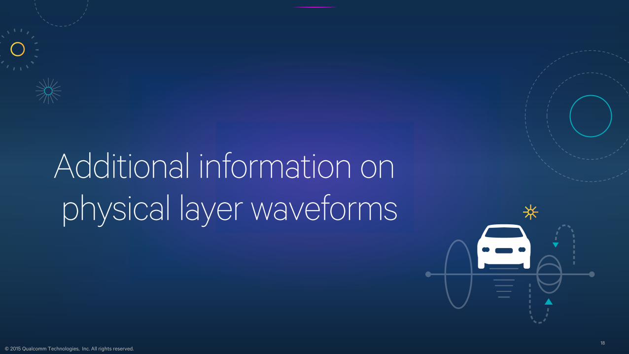
Weighted Overlap and Add (WOLA)Significant improvement to out-of-band and in-band asynchronous user interference suppression
24
WOLA processing at Transmitter (Tx-WOLA)
IFFT output
CP
Overlappedextension
Overlappedextension
Left soft edge Right soft edge
Transmitted Waveform
WOLA processing at Receiver (Rx-WOLA)
Practical implementations using time domain windowing
Received WaveformCP
IFFT input
Overlap and add
Receive weighting
(along window edges)
Weightingfunction A
Weightingfunction B

© 2015 Qualcomm Technologies, Inc. All rights reserved.
Improved OOB performance with WOLA
25
Significant improvement to OOB leakage performance
using time-domain windowing (WOLA)
Higher OOB leakage than SC-QPSK due to
discontinuities between OFDM transmission blocks
PSD of SC-FDM without WOLA PSD of SC-FDM with WOLA
Assumptions: SC-FDM: 60 symbols per run, 1000 runs. CP length is set to be roughly 10% of the OFDM symbol length. For Tx-WOLA, raised-cosine edge with rolloff α≈0.64 is used.
-300 -200 -100 0 100 200 300-100
-90
-80
-70
-60
-50
-40
-30
-20
-10
0
Normalized freq [1/T]
dB
SC-DFT:cp=0.1, tx wola=0,64 tones,60 symbols per run,1000 runs
SC-DFT: clip at6dB
SC-DFT: clip at8dB
SC-DFT: no clipping
SC-QPSK
SC-FDM
SC-FDM
SC-FDM
-300 -200 -100 0 100 200 300-100
-90
-80
-70
-60
-50
-40
-30
-20
-10
0
Normalized freq [1/T]
dB
SC-DFT:cp=0.1, tx wola=0.078,64 tones,60 symbols per run,1000 runs
SC-DFT: clip at6dB
SC-DFT: clip at8dB
SC-DFT: no clipping
SC-QPSK
SC-FDM
SC-FDM
SC-FDM

© 2015 Qualcomm Technologies, Inc. All rights reserved.
Zero-Tail SC-FDM
26
Transmitter
Receiver
Key characteristics
• Pros:
- Flexible bandwidth assignment
- No CP but support variable zero tail length, based
on channel delay spread on a per-user basis
- Improved spectral efficiency for some users – up to
7% due to removal of CP
- Better OOB suppression than DFT-spread OFDM
but worse than DFT-spread OFDM with WOLA
• Cons:
- Need synchronous multiplexing
- Extra signaling overhead to configure zero-tail
- Lack of CP makes multiplexing with OFDM less
flexible due to different symbol size
S/P M-DFT N-IFFT P/S
n zeros at tail 0
0h zeros at head
𝑑0, 𝑑1, ⋯ 𝑑𝑀−1−ℎ−𝑛
M-IDFTS/P
discard
FDE
M
discard
N-FFT P/S
Discard n zeros
Discard h zeros
𝑑0, 𝑑1, ⋯ 𝑑𝑀−1−ℎ−𝑛

© 2015 Qualcomm Technologies, Inc. All rights reserved.
CP-OFDM waveform
27
Transmitter
Receiver
Key characteristics
• Pros:
- Efficient implementation using FFT/IFFT
- Flexible spectrum allocation to different users
- Straight-forward application of MIMO technology:
- Flexible signal and data multiplexing, e.g. placement
of pilot across the frequency-time grid for channel
estimation
- Simple FDE for multipath interference mitigation
• Cons:
- Poor frequency localization due to the
rectangular prototype filter (without WOLA)
- Can be significantly improved using WOLA
• Example applications:
- CP-OFDM with WOLA is used in LTE downlink
P/SS/P
discard
CP
removalFDE
M
discard
N-FFT𝑑0, 𝑑1, ⋯ 𝑑𝑀−1
WOLA*S/PAdd
CPN-IFFT P/S
0
0
𝑑0, 𝑑1, ⋯ 𝑑𝑀−1
* WOLA is not in LTE spec. but existing implementations typically include WOLA to meet performance requirements

© 2015 Qualcomm Technologies, Inc. All rights reserved.
-50 -40 -30 -20 -10 0 10 20 30 40 50-100
-90
-80
-70
-60
-50
-40
-30
-20
-10
0
Normalized freq [1/T]
dB
WOLA: cp=0.1 txWola=0.078,12 tones,60 symbols per run,1000 runs
CP-OFDM: no clipping
WOLA: clip at 6dB
WOLA: clip at 8dB
WOLA: no clipping
+WOLA
+WOLA
+WOLA
WOLA substantially improves OOB performance
28
Assumptions: 12 contiguous data tones, 60 symbols per run, 1000 runs. CP length is set to be roughly 10% of the OFDM symbol length. For Tx-WOLA, raised-cosine edge with rolloff α≈0.8 is used.
PSD of CP-OFDM with WOLA at the transmitter
WOLA substantially
improves CP-OFDM
OOB leakage
performance

© 2015 Qualcomm Technologies, Inc. All rights reserved.
Universal-Filtered Multi-Carrier (UFMC)
29
Transmitter
Receiver
Key characteristics
• Use band-pass Tx filter to suppress OOB leakage:
- Each Resource Block (RB) has a corresponding Tx
filter, which is designed to only passes the assigned RB
- A guard interval of zeros is added between successive
IFFT symbols to prevent ISI due to Tx filter delay
• Pros:
- Similar OOB performance as CP-OFDM with WOLA
- Can be used to multiplex user with different
numerologies (similar to CP-OFDM with WOLA)
• Cons:
- More complex transmitter/receiver design
- Subject to ISI due to the lack of CP
P/S
S/P 2N-FFT
P/S
𝑑1,1, 𝑑1,2
, 𝑑1,3, ⋯
𝑑2,1, 𝑑2,2
, 𝑑2,3, ⋯
S/PTx
filter 1N-IFFT P/S
0
0
RB1
S/PTx
filter 2N-IFFT P/S
0
RB2 0
Add zero guard
Add zero guard
𝑑1,1, 𝑑1,2, 𝑑1,3 ⋯
𝑑2,1, 𝑑2,2, 𝑑2,3 ⋯

© 2015 Qualcomm Technologies, Inc. All rights reserved.
Additional details on UFMC transmitter/receiver processing
30
Transmit waveform for symbol 1
Transmit waveform for symbol 2
IFFT output(symbol 1)
Txfiltering
Tx filterlength
IFFT output(symbol 2)
UFMC processing at the transmitter
Received waveform
Zero padding
2x size FFT input
Tx filterlengthFFT size
UFMC processing at the receiver
© 2015 Qualcomm Technologies, Inc. All rights reserved.
-60 -40 -20 0 20 40 60-100
-90
-80
-70
-60
-50
-40
-30
-20
-10
0
Normalized freq [1/T]
dB
UFMC:12 tones,60 symbols per run,1000 runs
WOLA: clip at 8dB
UFMC: clip at 6dB
UFMC: clip at 8dB
UFMC: no clipping
UFMC has comparable OOB performance as CP-OFDM+WOLA
31
Note: WOLA refers to CP-OFDM with WOLA
Assumptions: 12 contiguous data tones, 60 symbols per run, 1000 runs. Chebyshev filter is used for the tx filter. FFT and RB sizes are set to be 1024 and 12 respectively. Chebyshev filter has 102 taps, which corresponds to 10%
CP, and has 60 dB of relative side-lobe attenuation
PSD of UFMC at the transmitter
Comparable OOB
leakage performance
as CP-OFDM+WOLA

© 2015 Qualcomm Technologies, Inc. All rights reserved.
Filter bank multi-carrier (FBMC)
32
FBMC/OQAM Transmitter
FBMC waveform synthesisKey characteristics
• Improve spectral property using prototype filter with
frequency domain over-sampling:
- Prototype filter spans multiple symbol periods, T
- Adjacent symbols are overlapped & added in time with
offset T to maintain spectral efficiency
- Overlap-and-add leads to potential ISI and ICI:
- Use half-Nyquist prototype filter to mitigate ISI
- Use “Offset-QAM” (OQAM) modulation to remove ICI
• Pros:
- Superior side-lobe decay than other MC waveforms
but the benefit reduces with PA non-linearity
• Cons:
- Complicated receiver design due to OQAM
- Subject to ISI under non-flat channel
- More complex MIMO integration than OFDM
S/P 4N-IFFT P/S
0
0
P(W)4X
Over-sampling
Prototypefilter
𝑑0,𝑘, 𝑑1,𝑘, ⋯ 𝑑𝑀−1,𝑘
FBMC waveform
synthesis
FBMC waveform
synthesis
Delay by
T/2
𝑅𝑒𝑎𝑙(𝑑0,𝑘)
Imag (𝑑1,𝑘)
𝑅𝑒𝑎𝑙(𝑑2,𝑘)
𝑅𝑒𝑎𝑙(𝑑𝑀−1,𝑘)
𝐼𝑚𝑎𝑔(𝑑0,𝑘)
R𝑒𝑎𝑙(𝑑1,𝑘)
𝐼𝑚𝑎𝑔(𝑑2,𝑘)
𝐼𝑚𝑎𝑔(𝑑𝑀−1,𝑘)

© 2015 Qualcomm Technologies, Inc. All rights reserved.
FBMC prototype filterImprove spectral property using prototype filter with frequency domain over-sampling
33
Frequency-domain response with oversampling factor K=4 (frequency between samples: 1/4T)
Time-domain response
(spanning multiple symbol periods T)
Increased block processing latency can remove the benefits of asynchronous transmission
-2 -1.5 -1 -0.5 0 0.5 1 1.5 2-0.2
0
0.2
0.4
0.6
0.8
1
1.2
OFDM symbol period ( T )
No
rma
lize
d a
mp
litu
de
OFDM windowing pulse shape
FBMC, K=4
WOLA, =0.07
CP-OFDM
Note: WOLA refers to CP-OFDM with WOLA
© 2015 Qualcomm Technologies, Inc. All rights reserved.
-200 -150 -100 -50 0 50 100 150 200-60
-50
-40
-30
-20
-10
0
Normalized freq [1/T]
dB
Ntones =96
FBMC: clip at 8dB
FBMC: no clipping
CP-OFDM w/ WOLA, clip at 8dB
CP-OFDM w/ WOLA, no clipping
FBMC’s OOB performance degrades with PA non-linearity
34Assumptions: FBMC has 24 tones, 60 symbols per run, 1000 runs. For a fair comparison to other multi-carrier waveforms, the overall FBMC symbol duration is normalized to T, which is the same as the CP-OFDM symbol duration.
PSD of FBMC at the transmitter
FBMC side-lobe
decays faster than
CP-OFDM+WOLA
with no PA clipping
OOB leakage
suppression
performance reduces
with PA clipping
Downlink transmissions are synchronized and additional improvement in OOB emission performance
at the expense of added implementation complexity and less-efficient MIMO support is not preferred

© 2015 Qualcomm Technologies, Inc. All rights reserved.
Generalized frequency division multiplexing (GFDM)
35
Key characteristics
• Similar to FBMC where prototype filter is used to
suppress OOB leakage. However, for GFDM:
- Multiple OFDM symbols are grouped into a block, with
a CP added to the block
- Within a block, the prototype filter is “cyclic-shift” in
time, for different OFDM symbols
• Pros:
- Better OOB leakage suppression than CP-OFDM
(same as CP-OFDM with WOLA)
• Cons:
- Complicated receiver to handle ISI/ICI
- Prototype filter may require more complicated
modulation/receiver, e.g. OQAM as in FBMC
- Higher block processing latency (no pipelining)
- Multiplexing with CP-OFDM requires large guard band
Time
Frequency
B
TT/M
M/T
M samples
M Subsymbols
K Subcarriers
CP Data Data Data Data Data Data CS
CP
Data CP
DataCP
Data CP
Data CP
Data CP
Data
GFDM
OFDM
K samples

© 2015 Qualcomm Technologies, Inc. All rights reserved.
-50 -40 -30 -20 -10 0 10 20 30 40 50-100
-90
-80
-70
-60
-50
-40
-30
-20
-10
0
Normalized freq [1/T]
dB
GFDM: cp=0.1, txWola=0.08,3 tones,9 subsymbols,6 symbols per run,1000 runs
CP-OFDM
GFDM w/o windowing
GFDM with windowingGFDM + WOLA
GFDM
GFMD has comparable OOB performance as CP-OFDM
36
PSD of GFMD at the transmitter
Comparable OOB
leakage performance as
legacy CP-OFDMTime-domain windowing
(like WOLA) significantly
reduces OOB leakage
Assumptions: 3 tones, 9 sub-symbols, 6 symbols per run, 1000runs. CP length is set to be roughly 10% of the OFDM symbol length. For Tx-WOLA, raised-cosine edge with rolloff α≈0.8 is used.

© 2015 Qualcomm Technologies, Inc. All rights reserved.
Single-carrier waveform has comparatively lower PAPR
37
OFDM-based multi-carrier waveform delivers higher spectral efficiency and is suitable for downlink where energy efficiency
requirement is more relaxed. Single carrier waveform can be used for other scenarios requiring high energy efficiency.
0 1 2 3 4 5 6 7 8 9 1010
-4
10-3
10-2
10-1
PAPR [dB]
CD
F
PAPR
FBMC
OFDM-WOLA
UFMC
GFDM-WOLA
SC-DFT-OFDM WOLA
ZT-DFT-OFDM
QPSK
QPSK+HPSK
SC-FDM + WOLA
Zero-Tail SC-FDM
GFDM + WOLA
CP-OFDM + WOLA

© 2015 Qualcomm Technologies, Inc. All rights reserved.38
Additional information on
multiple access techniques

© 2015 Qualcomm Technologies, Inc. All rights reserved.
Potential multiple access schemes
39
BW
Freq
TimeT
FDMA+TDMA
T
BW
Freq
Time
RSMA, SCMA, MUSA
BW
Freq
T
FDMA
BW
Freq
T
TDMA
Orthogonal multiple access Non-orthogonal multiple access
Multiple access techniques: Non-orthogonal FDMA FDMA+TDMA (1RB/user)
Effective Rate (kbps) 50 50 100
EbNo** (dB) -1.52 -0.73 -0.73
Link budget (dB) 146.1 145.3 142.3
Example comparison of orthogonal and non-orthogonal multiple access techniques*
* Assumptions: 12 users, 500 bits/10ms over 1 MHz bandwidth, 2Rx, an RB = 180kHz. **Derived using Shannon formula.

© 2015 Qualcomm Technologies, Inc. All rights reserved.
Resource Spread Multiple Access (RSMA)
40
Single carrier RSMA
Deliver better PA efficiency and has no synchronization
requirement
Multi-carrier RSMA
Exploit wider bandwidth to achieve lower latency for less
power-constrained applications
Add
CP
Spreader/
Scrambler
Interleaver
(optional)Coder
Add
CP
Spreader/
Scrambler
Interleaver
(optional)Coder S/P IFFT P/S
Key characteristics
• Spread user signal across time and/or frequency
resources:
- Use lower rate channel coding to spread signal across
time/frequency to achieve lower spectral efficiency
- Users’ signals can be recovered simultaneously even
in the presence of mutual interference
• RSMA is more robust:
- Coding gain provides EbNo efficiency compared with
orthogonal spreading or simple repetition
- More powerful codes can be employed than simple
repetition combined with low rate convolution codes
© 2015 Qualcomm Technologies, Inc. All rights reserved.
Sparse code multiple access (SCMA)
41
Key characteristics
• SCMA is based on Low Density Signature (LDS) CDMA
- Lower-density spreading
- Only partially uses the available time/frequency resources
• But unlike LDS-CDMA, SCMA uses multi-dimensional
constellations:
- Each user has a unique codebook which maps each of M
codewords to a length N constellation
- The length N constellation is extended to length L by
inserting L-N zeros.
• Requires iterative multiuser joint detection
LDS
spreading
QAM
modulation
FEC
encoder
X 0 0 X 0 XX
LDS spreading encoderFEC
encoder
X 0 0 Y 0 Z
SCMA
LDS-CDMA

© 2015 Qualcomm Technologies, Inc. All rights reserved.42
Appendix

© 2015 Qualcomm Technologies, Inc. All rights reserved.
References
43
1. “5G White Paper”, Next Generation Mobile Networks (NGMN) Alliance, March 2015. Available at http://ngmn.org/home.html
2. “Waveform contenders for 5G - OFDM vs. FBMC vs. UFMC”, F. Schaich, T. Wild, Alcatel-Lucent, 6th International Symposium on Communications, Control and Signal Processing
(ISCCSP), May 2014.
3. “What will 5G be?” J. Andrews, S. Buzzi, W. Choi, S. Hanly, A. Lozano, A. Soong, J. Zhang, IEEE Journal On Sel. Areas in Comm., Vol. 32, No. 6, June 2014.
4. “Power amplifier linearization with digital pre-distortion and crest factor reduction,” R. Sperlich, Y. Park, G. Copeland, and J.S. Kenney, Microwave Symposium Digest, 2004 IEEE MTT-S
International, Vol. 2, June 2004.
5. “Iterative Precoding of OFDM-MISO with Nonlinear Power Amplifiers”, I. Iofedov, D. Wulich, I. Gutman, IEEE International Conference on Communications, June 2015.
6. Ultra Low Power Transceiver for Wireless Body Area Networks, J. Masuch and M. Delgado-Restituto, Springer 2013.
7. “Channel coding with multilevel/phase signals,” G. Ungerboeck, IEEE Transactions on Information Theory, Vol 28, Issue 1, 1982.
8. “Frequency Domain Equalization for Single-Carrier Broadband Wireless Systems,” D. Falconer, S.L. Ariyavisitakul, A. Benyamin-Seeyar, D. Eidson, IEEE Communications Magazine, April
2002.
9. “Generalized Frequency Division Multiplexing for 5th Generation Cellular Networks,” N. Michailow, M. Matthé, I.S. Gaspar, A.N. Caldevilla, L.L. Mendes, A. Festag, G. Fettweis, IEEE
Transaction on Communications, Vol. 62, No. 9, September 2014.
10. “Performance of FBMC Multiple Access for Relaxed Synchronization Cellular Networks”, J.-B. Dore, V. Berg, D. Ktenas, IEEE Globecom, 2014
11. “FBMC receiver for multi-user asynchronous transmission on fragmented spectrum”, J.-B. Dore, V. Berg, N. Cassiau, D. Ktenas”, EURASIP Journal on Advances in Signal Processing, Vol.
41, March 2014
12. X. Wang, T. Wild, F. Schaich, A. Santos, Alcatel-Lucent, “Universal Filtered Multi-Carrier with Leakage-Based Filter Optimization”, European Wireless 2014.
13. J. G. Proakis, M. Salehi, Communication Systems Engineering, Prentice Hall, Inc. Upper Saddle River, New Jersey
14. D. A. Guimaraes, “Contributions to the understanding of the MSK Modulation”, REVISTA Telecommunications, vol. 11, no. 01, MAIO DE 2008
15. K. Murota, K. Hirade, “GMSK Modulation for digital mobile radio telephony”, IEEE Trans. Comm. Vol. COM-29, No. 7, July 1981.
16. “IEEE standard for local and metropolitan area networks – Part 15.4: low-rate wireless personal area networks (LR-WPANs)”, IEEE computer society.
17. P. A. Laurent, “Extract and approximate construction of digital phase modulations by superposition of amplitude modulated pulses (AMP)”, IEEE Trans. Comm., vol. COM-34, pp. 150-
160, 1986.
18. P. Jung, “Laurent’s representation of binary digital continuous phase modulated signals with modulation index ½ revisited”, IEEE Trans. Comm., vol. 42, no. 2-4, pp. 221-224, 1994.
19. F. Khan, “LTE for 4G Mobile Broadband: Air Interface Technologies and Performance”, Cambridge University Press, 2009.
20. G Berardinelli, F. M. L. Tavares, T. B. Sorensen, P. Mogensen, K. Pajukoski, Aalborg University/Nokia, “Zero-tail DFT-spread-OFDM Signals”, IEEE Globecom 2013.

© 2015 Qualcomm Technologies, Inc. All rights reserved.
References
44
21. R. W. Chang, “High-speed multichannel data transmission with bandlimited orthogonal signals”, Bell Sys. Tech. J., vol. 45, pp. 1775-1796, Dec. 1966.
22. B. R. Saltzberg, “Performance of an efficient parallel data transmission system”, IEEE Trans. Comm. Tech. vol. 15, no. 6, pp. 805-811, Dec. 1967.
23. B. Farhang-Boroujeny, “OFDM versus filter bank multicarrier: development of broadband communication systems”, IEEE Signal Proc. Magazine, pp. 92-112, May 2011.
24. M. Bellenger, “FBMC physical layer: a primer”, Phydyas report, 2010
25. J. Fang, Z. You, J. Li, R. Yang, I.T. Lu, “Comparisons of filter bank multicarrier systems”, System, Applications and Technology Conference, IEEE long island, May 2013, pp. 1-6.
26. M. Najar, C. Bader, F. Rubio, E. Kofidis, M. Tanda, J. Louveaux, M. Renfors, D. L. Ruyet, “MIMO channel matrix estimation and tracking”, PHYDYAS deliverables D4.1, Jan. 2009.
27. L. Ping, L. Liu, K.Y. Wu, W.K. Leung, “Interleave division multiple-access”, IEEE Trans. Wireless Comm., vol. 5, no. 4, pp. 938-947, Apr. 2006.
28. J. Soriaga, J. Hou, J. Smee, “Network performance of the EV-DO CDMA reverse link with interference cancellation”, IEEE Globecom 2006.
29. Y. Jou, R. Attar, C. Lott, J. Ma, R. Gowaikar, “CDMA and SC-FDMA reverse link comparison for cellular voice and data communications”, IEEE VTC 2010.
30. R. Hoshyar, F.P. Wathan, R. Tafazolli, “Novel Low-Density Signature for Synchronous CDMA Systems Over AWGN Channel”, IEEE Trans. on Signal Processing, vol. 56, No. 4, pp. 1616 -
1626, April 2008
31. K. Au, et al. “Uplink contention based SCMA for 5G radio access”, IEEE Globecom 2014 (Workshop on Emerging Technologies for 5G Wireless Cellular Networks), December 8-12,
Austin, TX, USA
32. M. Taherzadeh, H. Nikopour, A. Bayesteh, H. Baligh, “SCMA Codebook Design”, IEEE Vehicular Technology Conference, Sept. 2014
33. “White Paper on 5G Concept”, IMT-2020 (5G) Promotion Group Release Ceremony, Feb. 2015
34. “How to Improve OFDM-like Data Estimation by Using Weighted Overlapping”, C.V. Sinn, 11th International OFDM Workshop, 2006.
35. P. J. Black, Q. Wu, “Link Budget of cdma2000 1xEV-DO Wireless Internet Access System”, IEEE International Conference on Communications 2002.
36. “5G Design Across Services”, Johannesberg Summit, Stockholm, May 2015.
37. A. El Gamal, Y. Kim, “Network Information Theory”, Cambridge University Press, 2011.

© 2015 Qualcomm Technologies, Inc. All rights reserved.
List of Abbreviations
45
Abbreviation DefinitionACLR Adjacent Channel Leakage Ratio
CDMA Code Division Multiple Access
CP Cyclic prefix
CP-OFDM OFDM with Cyclic Prefix
D2D Device-to-Device Communication
DFT Discrete Fourier Transform
DL Downlink
eMBB Enhanced Mobile Broadband
EVDO Evolution-Data Optimized
FBMC Filter Bank Multi-Carrier
FDE Frequency Domain Equalization
FDM Frequency Division Multiplexing
FDMA Frequency Division Multiple Access
FEC Forward Error Correction
FFT Fast Fourier Transform
GFDM Generalized Frequency Division Multiplexing
GMSK Gaussian Minimum Shift Keying
GSM Global System for Mobile Communications
HARQ Hybrid Automatic Repeat Request
IAB Integrated Access and Backhaul
IFFT Inverse Fast Fourier Transform
IoT Internet of Things
LE Low Energy
ICI Inter Carrier Interference
ISI Inter Symbol Interference
LDS-CDMA Low Density Signature CDMA
LTE Long Term Evolution
MAC Multiple Access Control Layer
MC Multi-Carrier
MIMO Multiple-Input Multiple-Output
Abbreviation DefinitionmmWave Millimeter Wave
MSK Minimum Shift Keying
MUSA Multi-User Shared Access
MU-MIMO Multiuser MIMO
OFDM Orthogonal Frequency Division Multiplexing
OFDMA Orthogonal Frequency Division Multiple Access
OOB Out of Band Emissions
OQAM Offset-QAM
PA Power Amplifier
PAPR Peak-to-Average Power Ratio
PHY Physical Layer
P/S Parallel-to-Serial
PSD Power Spectral Density
QAM Quadrature Amplitude Modulation
RB Radio Block
RSMA Resource Spread Multiple Access
RX Receiver
SC-DFT-Spread OFDM Single Carrier Discrete Fourier Transform Spread OFDM
SC-FDE Single Carrier Frequency Domain Equalization
SC-FDM Single Carrier Frequency Division Multiplexing
SCMA Sparse Code Multiple Access
S/P Serial-to-Parallel
SRS Sounding Reference Signal
TDD Time Division Duplexing
TDMA Time Division Multiple Access
TX Transmitter
UFMC Universal Filter Multi-Carrier
UL Uplink
UMTS Universal Mobile Telecommunications System
WOLA Weighted Overlap and Add filtering
ZT-SC-DFT-Spread OFDM Zero-Tail Single Carrier DFT Spread OFDM

© 2015 Qualcomm Technologies, Inc. and/or its affiliates.
For more information on Qualcomm, visit us at:
www.qualcomm.com & www.qualcomm.com/blog
Thank youFollow us on:
©2013-2015 Qualcomm Technologies, Inc. and/or its affiliated companies. All Rights Reserved.
Qualcomm is a trademark of Qualcomm Incorporated, registered in the United States and other countries. Why Wait, Snapdragon, VIVE and MuLTEfire are trademarks of
Qualcomm Incorporated. Other product and brand names may be trademarks or registered trademarks of their respective owners.
References in this presentation to “Qualcomm” may mean Qualcomm Incorporated, Qualcomm Technologies, Inc., and/or other subsi diaries or business units within the
Qualcomm corporate structure, as applicable.
Qualcomm Incorporated includes Qualcomm’s licensing business, QTL, and the vast majority of its patent portfolio. Qualcomm Technologies, Inc., a wholly-owned subsidiary
of Qualcomm Incorporated, operates, along with its subsidiaries, substantially all of Qualcomm’s engineering, research and de velopment functions, and substantially all of its
product and services businesses, including its semiconductor business, QCT.
46
Recommended


![Waveform Design for 5G and Beyond · 2019-02-19 · arXiv:1902.05999v1 [eess.SP] 15 Feb 2019 1 Waveform Design for 5G and Beyond Ali Fatih Demir1, Mohamed Elkourdi1, Mostafa Ibrahim2,](https://img.pdfslide.us/doc/110x75/5f09d5027e708231d428b3cd/waveform-design-for-5g-and-beyond-2019-02-19-arxiv190205999v1-eesssp-15-feb.jpg)