Embed Size (px)
Citation preview
1
Prospective Multiple Antenna Technologies for
Beyond 5G
Jiayi Zhang, Member, IEEE, Emil Bjornson, Senior Member, IEEE, Michail
Matthaiou, Senior Member, IEEE, Derrick Wing Kwan Ng, Senior
Member, IEEE, Hong Yang, Senior Member, IEEE, and
David J. Love, Fellow, IEEE
Abstract
Multiple antenna technologies have attracted much research interest for several decades and have
gradually made their way into mainstream communication systems. Two main benefits are adaptive
beamforming gains and spatial multiplexing, leading to high data rates per user and per cell, especially
when large antenna arrays are adopted. Since multiple antenna technology has become a key component
of the fifth-generation (5G) networks, it is time for the research community to look for new multiple
antenna technologies to meet the immensely higher data rate, reliability, and traffic demands in the
beyond 5G era. Radically new approaches are required to achieve orders-of-magnitude improvements
in these metrics. There will be large technical challenges, many of which are yet to be identified. In
The work of J. Zhang was supported by National Natural Science Foundation of China under Grant 61971027, Beijing NaturalScience Foundation under Grants 4182049 and L171005, Science and Technology Key Project of Guangdong Province Chinaunder Grant 2019B010157001, and the ZTE Corporation. The work of E. Bjornson was supported by ELLIIT and the SwedishResearch Council. The work of M. Matthaiou was supported by a research grant from the Department for the Economy NorthernIreland under the US-Ireland R&D Partnership Programme and by the EPSRC, U.K., under Grant EP/P000673/1. The work ofD. Love was supported in part by the National Science Foundation (NSF) under grant CCF1816013. The work of D. W. K.Ng was supported by funding from the UNSW Digital Grid Futures Institute, UNSW, Sydney, under a cross-disciplinary fundscheme and by the Australian Research Council’s Discovery Project (DP190101363). (Corresponding Author: Jiayi Zhang)
J. Zhang is with the School of Electronic and Information Engineering, Beijing Jiaotong University, Beijing 100044, P. R.China. (e-mail: [email protected]).
E. Bjornson is with the Department of Electrical Engineering (ISY), Linkoping University, Linkoping, Sweden. (e-mail:[email protected]).
M. Matthaiou is with the Institute of Electronics, Communications and Information Technology (ECIT), Queen’s UniversityBelfast, UK, BT3 9DT. (e-mail: [email protected]).
D. W. K. Ng is with the School of Electrical Engineering and Telecommunications, University of New South Wales, NSW2052, Australia. (e-mail: [email protected]).
H. Yang is with Nokia Bell Labs, Murray Hill, NJ 07974 USA. (e-mail: [email protected]).
D. J. Love is with the School of Electrical and Computer Engineering, Purdue University, West Lafayette, IN 47907 USA.(e-mail: [email protected])
arX
iv:1
910.
0009
2v3
[cs
.IT
] 2
4 M
ar 2
020

2
this paper, we survey three new multiple antenna technologies that can play key roles in beyond 5G
networks: cell-free massive MIMO, beamspace massive MIMO, and intelligent reflecting surfaces. For
each of these technologies, we present the fundamental motivation, key characteristics, recent technical
progresses, and provide our perspectives for future research directions. The paper is not meant to be
a survey/tutorial of a mature subject, but rather serve as a catalyst to encourage more research and
experiments in these multiple antenna technologies.
Index Terms
Beyond 5G, cell-free massive MIMO, beamspace, intelligent reflecting surface.
I. INTRODUCTION
THE demand for higher data rates and traffic volumes seems to be never-ending, thus
the quest for delivering the required services must also continue. The cellular network
technology has evolved from using fixed sector antennas to flexible multiple antenna solutions.
Recently, the first release of 5G New Radio (NR) was finished by the 3rd Generation Partnership
Project (3GPP) and the first commercial networks are already operational. In particular, massive
multiple-input multiple-output (MIMO), which are defined in [1] as having base stations with
i) at least 64 antennas and ii) a number of antennas at least an order of magnitude more than
the number of user equipments (UEs), is a key technology. However, this is not the end of
the MIMO development, but only the end of the beginning. As access to wireless connectivity
becomes critical in our everyday lives, our expectations of ubiquitous coverage and service quality
continue to grow. Many future requirements that can be conceived which cannot be addressed
by 5G; for example, exceptionally high bit rates, uniform user performance over the coverage
area, ultra-low latencies, great energy efficiency, robustness against blocking and jamming, and
wireless charging.
There is no simple way to meet these requirements. There has been significant focus on using
millimeter wave (mmWave) frequencies in 5G, since large unused bandwidths are available in
these frequency bands, which might translate into higher bit rates. Unfortunately, there are some
fundamental drawbacks with mmWave communications [2], [3]. First, the sensitivity to signal
blockage has not been resolved, despite significant research efforts that have been devoted to the
issue in the past decade. Second, the shorter wavelength in mmWave bands leads to a reduced
coherence time, thus one has to multiplex fewer data signals than in sub-6 GHz bands to achieve

3
the same signaling overhead for channel state information (CSI) acquisition. For example, even
if 10 times more bandwidth can be utilized in mmWave, the bit rate might not increase if 10
times fewer data signals can be multiplexed. These problems presumably become worse in the
sub-terahertz (THz) bands, above 0.1 THz, that are currently being studied for beyond 5G. The
bottom line is that there is a need to develop novel multiple antenna technologies that can be
applied in the valuable sub-6 GHz spectrum as well as in higher bands, and to consider both
time-division duplex (TDD) and frequency-division duplex (FDD) modes.
It is time to analyze what lies beyond 5G, or rather what the current multiple antenna tech-
nologies can potentially be evolved into beyond what is currently envisaged. Potential paradigm
shifts in wireless network design for beyond 5G are cell-free massive MIMO, beamspace mas-
sive MIMO, and intelligent reflecting surfaces (IRSs). These topics are covered in Section II,
Section III, and Section IV, respectively. New roles that these multiple antenna technologies
can play for unmanned aerial vehicle (UAV)-supported communication and in sub-THz bands
are discussed in Section V, while the main conclusions are provided in Section VI. There are
several tutorial papers on multiple antenna technologies, e.g. [4]–[8], and also textbooks such as
[9]–[13]. These provide an excellent introduction to the topic and also describe the developments
that lead to 5G. When it comes to beyond-5G technologies, [14], [15] are two recent papers
that describe prospective future technologies, but without providing any mathematical details. In
contrast, this paper provides a comprehensive description of the state-of-the-art in three selected
topics and includes all the theoretical details that are essential to conduct research on these topics.
Besides, various open research problems are discussed which sheds light on the development of
multiple antenna technologies for beyond-5G networks.
II. CELL-FREE MASSIVE MIMO
The 5G cellular technology can provide data rates and traffic volumes far above previous
cellular technologies, and will also reduce the latency of the data connections [16]. Yet, these
improvements are primarily achieved by UEs that happen to be located near the cell centers,
while the inter-cell interference and handover issues that inherent to the cellular architecture will
remain to limit the cell-edge performance. To address these issues, beyond-5G networks need
to enter the cell-free paradigm, where the absence of cell boundaries alleviates the inter-cell
interference and handover issues but also gives rise to new challenges.

4
A. Motivation
The first cellular networks were introduced in the 1970s to achieve more efficient use of the
limited radio resources [17]. Instead of requiring the data source to wirelessly communicate
directly with the UE, which might be located far away and thus require very high transmit
power, cellular networks consist of set of geographically distributed fixed access points (APs).
The data source sends its data to a nearby AP using relatively low power. The AP forwards the
data to an AP that is near the UE (typically over cables or other wireless bands) and can send
the data to the UEs with relatively low power. This enabled better spatial reuse of the frequency
spectrum and the AP densification has been the main way for cellular networks to handle higher
traffic volumes [18]. However, the AP densification also leads to more inter-cell interference and
more frequent handovers. Most of the traffic congestion in cellular networks nowadays is at the
cell edges, since cell-center UEs can easily run their preferred applications thanks to their lower
interference levels and higher achievable data rates. The so-called 95%-likely user data rates,
which can be guaranteed to 95% of the users and thus defines the user-experienced performance
[19], remain mediocre in 5G networks.
The solution to these issues might be to connect each user with a multitude of APs [20], [21]; if
there were only one huge cell in the network, there is by definition no inter-cell interference and
no need for handovers. This solution has been explored in the past, using names such as network
MIMO [21], [22], distributed MIMO [23], and coordinated multi-point (CoMP) [24]. However,
the practical implementation requires immense fronthaul signaling for CSI and data sharing, as
well as huge computational complexity. To reduce the fronthaul signaling and computational
complexity, a common approach was to divide the network into disjoint clusters containing
a few neighboring APs [25]–[27], so that only those need to exchange CSI and data. This
network-centric approach can provide some performance gains [28], but only partially address
the interference and handover issues, which remain along the cluster edges.
The key to fully resolve these issues is to let each user be served by those APs that can
reach it with non-negligible interference [29]–[31]. This creates a user-centric network [32],
where each AP collaborates with different sets of APs when serving different UEs. It is the
UEs that select which set of APs that it is best served by, not the network. Early experiments
with cell-free networks are described in [33], but it is first in recent years that the concept has
gained significant traction from academia [34], [35], where the name cell-free massive MIMO

5
has been coined [36]–[38]. In a nutshell, it is a combination of the best aspects of network
MIMO that were conceived in the last decade and the analytical framework from the massive
MIMO literature, recently surveyed in the textbooks [11], [12].
B. Basics of Cell-Free Massive MIMO
A cell-free massive MIMO network consists of a large number of APs that jointly and
coherently serves a much smaller number of UEs on the same time-frequency resource. The
network operates in TDD mode and exploits uplink-downlink channel reciprocity [37], [38],
so that each AP can acquire CSI between itself and all UEs from uplink pilots. This CSI is
sufficient to implement coherent transmission and reception [39], so only data signals must be
shared between APs. To enable such information flows, the APs are assumed to be connected
via fronthaul to cloud-edge processors that take care of data encoding and decoding. These are
often called central processing units (CPUs) in the literature and the structure is reminiscent of
the cloud radio access network (C-RAN) architecture [40]. One can thus view C-RAN as an
enabler of cell-free massive MIMO. The CPUs are normally assumed to only know the long-term
channel qualities, while only the APs have instantaneous CSI. Fig. 1 shows the basic network
architecture of a cell-free massive MIMO system.
The spectral efficiencies that UEs can achieve in cell-free massive MIMO have been analyzed
in a series of previous works. The original papers [37], [38] considered single-antenna APs,
single-antenna UEs, Rayleigh fading channels, and infinite capacity error-free fronthaul connec-
tions. Later works have studied more realistic setups, such as single-antenna APs with Rician
fading channels [41], [42], multi-antenna APs with uncorrelated [43], [44] or correlated [45],
[46] fading, multi-antenna UEs [47], [48], and hardware impairments [49], [50]. The impact
of finite-resolution fronthaul connections (i.e., when both CSI and the received signal must be
quantized) was considered in [44]. The general conclusion is that cell-free massive MIMO works
well in all these cases, thus it is suitable for a variety of deployment scenarios.
One performance benchmark for cell-free massive MIMO is a cellular network with the same
set of APs, but where each user is only served by one AP (i.e., a small-cell network). The first
paper on the topic showed that cell-free massive MIMO can achieve nearly fivefold improvement
in terms of 95%-likely per-user spectral efficiency [37]. If both the APs and the UEs are equipped
with multiple antennas, the 95%-likely per-user performance can be further enhanced [48].
Another relevant benchmark is conventional cellular massive MIMO, consisting of a relatively

6
AP l
Fronthaulconnection
@@@R
CPU
Figure 1: Illustration of the network architecture in cell-free massive MIMO.
small number of APs, each equipped with a large number of antennas. Such comparisons have
been carried out in [46], [51] and show that cell-free massive MIMO can substantially improve
the 95%-likely per-user spectral efficiency, while cellular massive MIMO is the preferred choice
for cell-center UEs. This emphasizes the point that the cell-free paradigm is not about achieving
higher peak performance, but a more uniform performance within the coverage area. A massive
macro-diversity gain is achieved by having many geographically distributed antennas; the average
distance between a UE and the closest APs reduces and the shadow fading is also combatted
by the diversity. Moreover, the energy efficiency of cell-free massive MIMO was considered in
[51], [52], which showed that it can improve the energy efficiency (measured in bit/Joule) by
nearly ten times compared to cellular massive MIMO. Hence, two main reasons to adopt cell-
free massive MIMO in beyond-5G networks is the vastly higher 95%-likely spectral efficiency
and energy efficiency.

7
AP l
User 1
AP cluster for user 1
User 2
AP cluster for user 2
User 3
AP cluster for user 3
Figure 2: Example of how different subsets Mk of APs serve three UEs (k = 1, 2, 3) in a cell-free massive MIMO system.
C. System Model and Key Characteristics
We will now explain the key characteristics of cell-free massive MIMO in further detail by
considering a basic system model. We assume there are L APs in the network, each equipped
with N antennas, and K single-antenna UEs. User k is served by a subset Mk ⊂ {1, . . . , L}of the APs, which have been selected in a user-centric manner. Fig. 2 exemplifies how the APs
can be divided into partially overlapping subsets when serving the UEs.
The channel between AP l and user k is denoted by hkl ∈ CN , and it is the same uplink and
downlink due to the TDD operation. The UEs send uplink pilots that enable AP l to compute
local estimates hkl of the channels to all UEs (k = 1, . . . , K) [53]. Different channel estimators
can be used depending on the channel model, but we will not cover those details to keep the
description general and short; we refer the interested readers to [42], [48], [54]. Deep learning
can also be used to estimate the channel [55], [56]. Irrespective of the choice of estimator,
pilot contamination appears in cell-free massive MIMO (just as in any large-scale network).
Fortunately, it appears to be less of a concern than in cellular massive MIMO since each AP
has few antennas and only serves a few UEs.
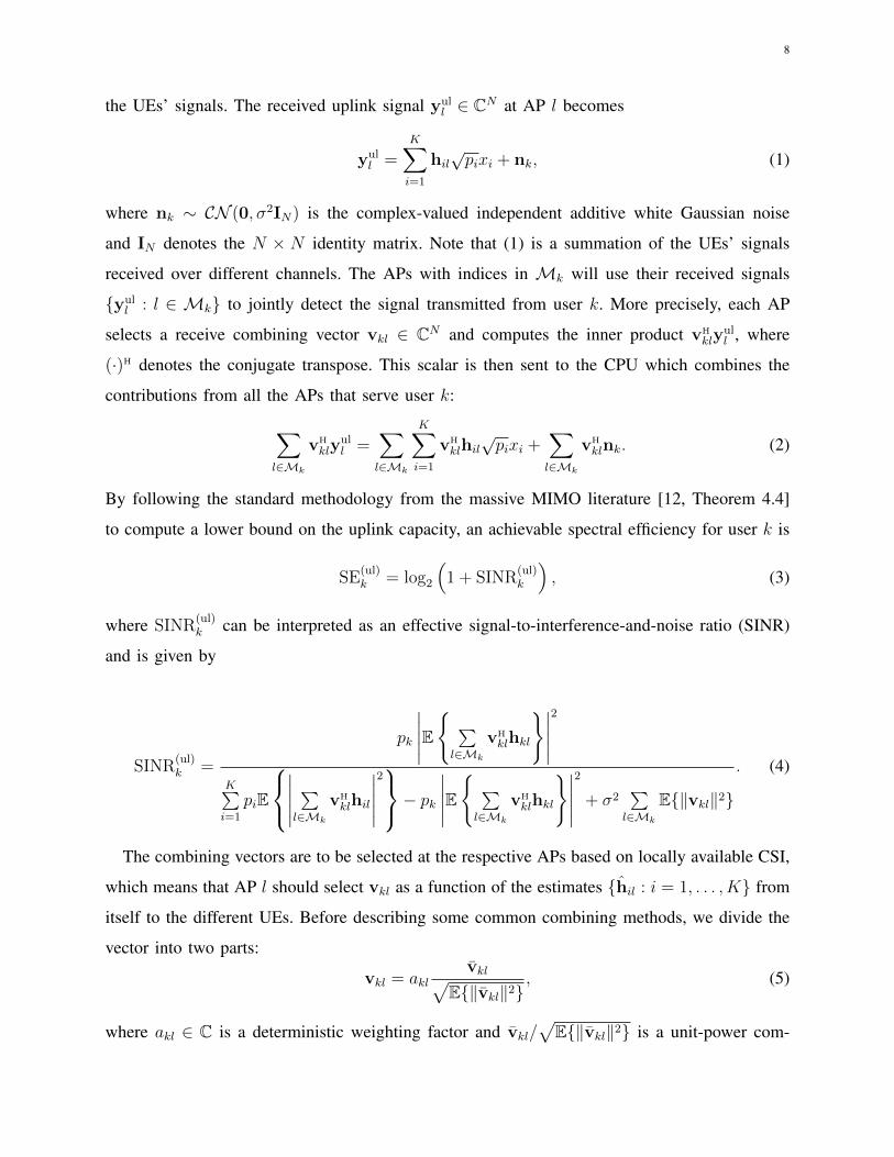
1) Uplink Data Transmission: Let xk denote the unit-power signal that user k wants to
send over the uplink. The user assigns a transmit power pk ≥ 0 to the signal and transmits
it simultaneously with all other UEs, thereby expecting that the network can spatially separate
8
the UEs’ signals. The received uplink signal yull ∈ CN at AP l becomes
yull =
K∑i=1
hil√pixi + nk, (1)
where nk ∼ CN (0, σ2IN) is the complex-valued independent additive white Gaussian noise
and IN denotes the N × N identity matrix. Note that (1) is a summation of the UEs’ signals
received over different channels. The APs with indices in Mk will use their received signals
{yull : l ∈ Mk} to jointly detect the signal transmitted from user k. More precisely, each AP
selects a receive combining vector vkl ∈ CN and computes the inner product vHkly
ull , where
(·)H denotes the conjugate transpose. This scalar is then sent to the CPU which combines the
contributions from all the APs that serve user k:
∑l∈Mk
vH
klyull =
∑l∈Mk
K∑i=1
vH
klhil√pixi +
∑l∈Mk
vH
klnk. (2)
By following the standard methodology from the massive MIMO literature [12, Theorem 4.4]
to compute a lower bound on the uplink capacity, an achievable spectral efficiency for user k is
SE(ul)k = log2
(1 + SINR
(ul)k
), (3)
where SINR(ul)k can be interpreted as an effective signal-to-interference-and-noise ratio (SINR)
and is given by
SINR(ul)k =
pk
∣∣∣∣∣E{ ∑l∈Mk
vHklhkl
}∣∣∣∣∣2
K∑i=1
piE
∣∣∣∣∣ ∑l∈Mk
vHklhil
∣∣∣∣∣2− pk
∣∣∣∣∣E{ ∑l∈Mk
vHklhkl
}∣∣∣∣∣2
+ σ2∑l∈Mk
E{‖vkl‖2}
. (4)
The combining vectors are to be selected at the respective APs based on locally available CSI,
which means that AP l should select vkl as a function of the estimates {hil : i = 1, . . . , K} from
itself to the different UEs. Before describing some common combining methods, we divide the
vector into two parts:
vkl = aklvkl√
E{‖vkl‖2}, (5)
where akl ∈ C is a deterministic weighting factor and vkl/√
E{‖vkl‖2} is a unit-power com-

9
bining vector that depends on the CSI. The purpose of the weighting factors is that APs with
good channel conditions should get higher weights and thereby have a large influence on the
combined signal in (2). The use of such weights is also known as large-scale fading decoding
[57], particularly when the weights are selected at the CPU based on channel statistics from the
entire network. A general expression for the optimal weights is found in [46].
The receive combining vectors can be computed in different ways. The original paper [37]
on cell-free massive MIMO considered maximal ratio (MR) combining, where vkl = hkl. This
method maximizes the received signal power without taking the existence of other UEs into
account. One key benefit of using this method is that expectations in (9) can often be computed
in closed form; for example, under uncorrelated [37] or correlated [46] Rayleigh fading and
for Rician fading [42]. However, higher spectral efficiencies are achieved by local minimum
mean-square error (L-MMSE) combining, for which the combining vector can be expressed as1
vkl =
( K∑i=1
pihilhH
il + σ2IN
)−1hkl. (6)
Interestingly, L-MMSE outperforms MR even in the case of single-antenna APs [46], [58], but
is not an optimal combining method since that would require all the APs to jointly selected their
receive combining.
We will now illustrate the performance behaviors. Fig. 3 shows the cumulative distribution
function (CDF) of the per-user spectral efficiency in a setup with L = 100 single-antenna APs
and K = 40 UEs uniformly distributed in a 1× 1 km square. We refer to [37] for further details
on the simulation parameters. The CDF is computed by considering different random realizations
of the AP and user locations.
There are three curves where all UEs transmit at full power and one curve where power control
is used to maximize the worst-user spectral efficiency in the network, using an algorithm from
[37]. The highest spectral efficiency is achieved by cell-free massive MIMO when using L-MMSE
combining and the optimal weights from [46]. All UEs benefit from using that method compared
to the case of small cells, where each user connects to the AP providing the highest value. It
is particularly the weakest “cell-edge” UEs that benefit from the cell-free approach, while UEs
that happen to be very close to an AP do not benefit much. If L-MMSE is replaced with MR,
the strongest UEs (which are interference-limited) lose in performance while the weakest UEs
1In some cases, the inverse matrix in (6) also includes the covariance matrices of the channel estimation errors; see [46].

10
0 0.5 1 1.5 2 2.5 3
0
0.2
0.4
0.6
0.8
1
Figure 3: The uplink spectral efficiency with different combining methods and power control schemes, using the simulationsetup from [37].
(which are noise-limited) are barely affected. If one further applies the power-control scheme
from [37], the 1% weakest UEs get an improvement in spectral efficiency but the gain is barely
visible since these UEs are noise-limited from the beginning.
The conclusion is that cell-free massive MIMO can greatly improve the performance for the
weakest UEs in a network. The gains are achieved by coherent processing of the signals received
at multiple APs. Power control policies can be used to shape the CDF curves in different ways.
The previous works [37], [57], [59] have considered the design of power control that maximizes
the worst-user performance, which might not be the desired optimization criterion since a minor
performance improvement comes at the price of reducing most UEs’ performance by a lot (as
shown in Fig. 3). Other power control schemes need to be developed in the future. One recent
example is [60].
2) Downlink Data Transmission: Let xk denote the unit-power downlink signal intended for
user k. Each AP l ∈ Mk that serves this user maps the scalar signal to its N antennas using
a precoding vector wkl ∈ CN , thus making wklxk the transmitted signal. When all APs follow
that procedure, the received downlink signal ydlk ∈ C at user k becomes
ydlk =K∑i=1
∑l∈Mi
hT
klwilxi + nk, (7)

11
where nk ∼ CN (0, σ2) is independent additive noise. By following a similar methodology as in
the uplink, an achievable spectral efficiency for user k is [12, Theorem 4.6]
SE(dl)k = log2
(1 + SINR
(dl)k
)bit/s/Hz, (8)
where SINR(dl)k can be interpreted as an effective SINR and is given by
SINR(dl)k =
∣∣∣∣∣E{ ∑
l∈Mk
hTklwkl
}∣∣∣∣∣2
K∑i=1
E
∣∣∣∣∣ ∑l∈Mi
hTklwil
∣∣∣∣∣2−
∣∣∣∣∣E{ ∑
l∈Mk
hTklwkl
}∣∣∣∣∣2
+ σ2
. (9)
The expectations in (9) are taken with respect to random channel fading realizations. One can
compute the SINR using Monte-Carlo simulations for any channel distribution and any way of
selecting the precoding vectors.
As described earlier, it is preferable if AP l selects its precoding vector based only on its
locally available CSI, which consists of the estimates {hil : i = 1, . . . , K} from itself to the
different UEs. Before describing some common precoding methods, we divide the vector into
two parts:
wkl =√ρkl
wkl√E{‖wkl‖2}
, (10)
where ρkl ≥ 0 represents the transmit power that AP l assigns to user k and wkl/√
E{‖wkl‖2}is a unit-power precoding vector that determines the spatial directivity of the signal.
Similar to the uplink, the original papers [37], [38] considered MR precoding, where wkl = h∗kl,
which is also known as conjugate beamforming since (·)∗ denotes complex conjugation. This
method directs the transmission towards the intended receiver without taking the existence of
other UEs into account. One key benefit of using this method is that expectations in (9) can
often be computed in closed form for many common channel models [42], [46]. However, it has
recently been shown in [58] that signal-to-leakage-and-noise ratio (SLNR) precoding with
wkl =
( K∑i=1
ρilh∗ilh
T
il + σ2IN
)−1h∗kl (11)
provides higher spectral efficiencies by balancing between maximizing the signal power at
the intended receiver and minimizing the interference that leaks to non-intended receivers.
Interestingly, SLNR outperforms MR even in the case of single-antenna APs [58] and the

12
computational complexity is almost the same. Nevertheless, SLNR precoding is not the optimal
method. Other papers consider similar methods such as full-pilot zero-forcing [61] and L-MMSE
[54] precoding.
For brevity, we will not provide any simulation results for the downlink, because the perfor-
mance of the different precoding methods are reminiscent of their uplink counterparts. However,
we stress that the selection of the transmit power ρkl is more complicated in the downlink than
in the uplink, because each AP needs to select how to distribute their power between different
UEs. Some different power allocation schemes are found in [37], [38], [62], but further work is
still required to deal with other criteria than the maximization of the worst UEs’ performance.
D. Scalable Large-Scale Deployment
The main challenge in designing cell-free massive MIMO is to achieve a network architecture
that is scalable in the sense of being implementable in a large network, spanning an entire city.
One way to define scalability is to consider the limit K →∞ and evaluate if the network could
still operate in that case [54]. More precisely, the computational complexity at each AP and
its fronthaul capacity requirement must be independent of K. All the combining and precoding
methods described above can be modified to satisfy that condition if each AP is only allowed to
serve a fixed number of UEs, irrespective of how large the network is. This is a natural restriction
since the UEs are typically distributed over the network and thereby close to different APs. It
was shown in [54] that this restriction has a negligible impact on the spectral efficiency.
Other issues are harder to implement in a scalable way. Downlink power allocation is one such
issue, where each AP needs to assign power to the UEs that it serves without having complete
knowledge about the channel conditions that other APs are facing. Any global power allocation
optimization must have a complexity that grows with K, thus making the implementation
infeasible in large networks. As a compromise approach, various heuristic power allocation
schemes can be found in [29], [38], [39], [62], but it lies in the nature of these schemes that
it is hard to evaluate how well they perform in practice. Hence, further work is necessary to
understand how to perform effective and scalable power allocation. On the other hand, an uplink
counterpart to downlink power allocation is the selection of the combining weights akl, which
can be selected optimally [46], [57] but the complexity will grow with K. There is currently
no good understanding how to select these weights in a distributed but effective manner. Uplink
power control can potentially also have an important impact.

13
There is also a series of papers that consider partially centralized precoding and combining for
cell-free massive MIMO [46], [54], [57], [63]. These methods allow for interference suppression
between APs, which can substantially increase the spectral efficiency. First steps toward a scalable
implementation of these methods are taken in [54].
Another aspect is related to cloud-RAN and the fronthaul infrastructure because a large
network will require multiple CPUs and the encoding/decoding tasks that need to be carried out
at the CPU level must be distributed between them. Some first works in these directions are found
in [33], [62], [64], but there is no quantitative comparison of different network infrastructures.
E. Open Research Problems
The above brief survey of cell-free massive MIMO provides a quick overview from its
inception to the state-of-the-art. Although much research has been carried out leading to much
scientific progress in recent years, there remain several important and interesting open research
problems which we believe are necessarily relevant in propelling the technology to the next
stage. We shall discuss three such problems, in no particular order, in the following.
1) Power Control: As already mentioned, power control, especially downlink power control,
still requires much research. The optimal power control coefficients, such as the ones for max-min
power control [37], [38], can be obtained using second-order cone programming. Unfortunately,
these methods are not fast enough for real-time implementation. Unlike cellular systems, where
downlink and uplink power controls are symmetric in the sense that each has the same number
of power control coefficients, there is a different number of coefficients in cell-free networks.
There are K coefficients in the uplink, while if each of the M APs is serving all K UEs, there
are MK power control coefficients in the downlink. Even when taking into account that only a
subset of APs Mk serves each user k, there will be∑K
k=1 |Mk| ≥ K coefficients to select in
the downlink, where |Mk| denotes the number of elements in Mk. Hence, the computational
complexity for downlink power control is particularly high. In a cellular system where each user
is served by a single AP, practical power control works to maintain a target SINR iteratively
for each user, i.e., when the target SINR for a particular user is exceeded, the allocated power
for that user is lowered and vice versa. It has been shown such algorithm converges [65]–[69]
under some very general assumptions. Nevertheless, this approach cannot be directly applied in
cell-free massive MIMO where each user is simultaneously served by many APs, which must
coordinate their decisions (some may increase their power while some may decrease) and must

14
also satisfy per-AP power constraints. Furthermore, the impact of real-world power control with
finite discrete power levels must also be investigated. In addition, how to use power control to
effectively strike a balance between sum spectral efficiency and user fairness is also not well
understood, since the max-min fairness approach may sacrifice too much sum spectral efficiency
to provide absolute fairness to all UEs. While the proportional fairness metric is often used in
cellular networks [12], [70], the picture can be quite different in cell-free networks, where the
UEs’ SINRs are distributed in a very different way. When it comes to the uplink, there is evidence
[46], [63] that full power transmission might work well in many practical scenarios. This marks
a significant departure from cellular thinking where full power transmission does not work for
the uplink [71]. We should mention that although there are only K power control coefficients,
they can interact with the∑K
k=1 |Mk| weights in (5). If these can be jointly optimized in a
computationally efficient way, further performance improvement may be achieved.
2) Fronthaul/Backhaul Provisioning: With a large number of APs scattered across the intended
coverage area, it is obvious that the burden of fronthaul/backhaul for cell-free networks will be
much heavier than that in traditional cellular systems. Wired provision via optical fiber is cost-
prohibitive except in premium venues or if serial connections can be used [34]. Wireless provision
is a viable option but comes with its own set of challenges such as the availability of spectrum and
all the difficulties of reliably delivering ultra-high data rates wirelessly. One idea is to use a “dual
layer” architecture where a cellular massive MIMO network hauls a cell-free massive MIMO
system [72]. For cell-free networks to become a successful reality, more out-of-the-box ideas
for fronthaul/backhaul provisions are undoubtedly needed and the best C-RAN methods must be
utilized. Another angle of attacking this same problem is to research the means of minimizing the
fronthaul/backhaul requirements, by decentralizing the processing as far as possible and heavily
quantize the signals sent over the fronthaul [44] or using distributed quantization techniques
[73]–[78]. A recent overview of the trade-offs between fronthaul requirements and the uplink
performance for some well-known processing schemes is provided in [46]. A main conclusion
is that there are opportunities to exploit the specificities of the fronthaul architecture to optimize
its utilization and create semi-distributed methods.
3) Network Scalability: One definition of “network scalability” from [54] was provided earlier,
based on letting K → ∞, but other definitions are also possible. Generally speaking, it refers
to the ability to meaningfully increase the performance of a small system by an “arbitrarily”
larger system. For massive MIMO, a larger system means a larger number of service antennas.

15
Taking the fronthaul/backhaul capacity and network computing power limitations into account,
a skeleton for scalable cell-free massive MIMO operation was provided in [54], [62]. But, how
to optimally and seamlessly associate each user to a group of APs and select the necessary
signal processing and power control remain very challenging problems—any attempt to globally
optimize these operations would be fundamentally unscalable. Another facet of scalability is
how the performance scales with respect to an increase of the number of APs, L, while keeping
the number of UEs K fixed. For example, it is shown in [63] that the uplink minimum data rate
does not scale with L when using MR processing. Scaling laws should also be investigated for
real-world channels, such as with mixed line-of-sight (LoS) and non-LoS propagation, and other
non-stationary channels [79], [80]. For LoS channels, approaches used in [81], [82] for cellular
networks can be adapted for cell-free networks [83].
III. BEAMSPACE MASSIVE MIMO
The more antennas that are used in a MIMO transceiver, and the higher the carrier frequency
and bandwidth are, the more complicated the implementation becomes. One way to reduce
the implementation complexity, without sacrificing too much in performance or operational
flexibility, is to utilize the spatial structure of the channels and transceiver hardware. In this
section, we describe beamspace massive MIMO, which is the general concept that underpins
hybrid beamforming and its future successors. We particularly focus on recent progress and open
problems related to using lens arrays for beamspace massive MIMO.
A. Motivation
Early research in single-user MIMO focused on open-loop techniques that achieve MIMO
benefits without any transmit-side knowledge of CSI. The most popular open-loop techniques are
diversity techniques (e.g. space-time block codes and space-time trellis codes) and multiplexing
techniques (e.g. spatial multiplexing) [84], [85]. The performance of these techniques is severely
limited, in terms of most measures of performance, because the transmission is not adapted to
the current CSI in any way.
In the early 2000s, the single-user MIMO research shifted to techniques that adapt the transmit
signal to the channel conditions using some level of transmit-side CSI [86]–[90]. The simplest
kind of this adaptation is linear precoding, where a multiple antenna open-loop signal is adapted
to the channel by multiplying it by a precoding matrix before transmission [86]. The benefit is

16
that spatial CSI adaptation is now encapsulated in the precoding matrix. Linear precoding has
had a widespread impact with inclusion in multiple standards including 4G Long-Term Evolution
(LTE), 5G NR, and versions of IEEE 802.11.
Because commercially available MIMO transmitters have typically had fewer than eight anten-
nas, linear precoding has historically been implemented using direct digital implementation. For
example, LTE Release 8 systems limit the base station to having at most four antenna ports. With
these small array sizes, direct digital processing of precoding was generally practical because
it is cost-effective for small arrays to use a relatively high-resolution analog-to-digital converter
(ADC) at each transmit element. In this kind of implementation, it is convenient to think of the
linear precoder as a single matrix and the transmit signal is multiplied by that matrix, avoiding
many sophisticated formulations of precoder design.
Commercial array sizes, however, are poised to scale dramatically over the coming years.
mmWave and massive MIMO transmitters equipped with on the order of a hundred antennas
are commonly discussed in the literature. As the number of antenna elements increases, there
are multiple benefits to rethinking the signal processing and implementation of linear precoding.
The most popular approach is using a beamspace MIMO formulation.
We firmly believe that beamspace terminology, notation, and thinking will be critical for
5G and beyond systems. In sub-6 GHz, the number of antennas will continue to increase. The
dimensionality of these arrays combined with the unique hardware characteristics (hybrid digital-
analog, sub-arraying, tiled arrays, etc.) will make it impractical, if not impossible, to sound
each array element. For this reason, MIMO processing will be best done using a subspace
approach based on virtual or effective channels. At mmWave frequencies and higher, beamspace
will be indispensable. These arrays will be large and may have non-traditional array hardware
implementations. Optical-like thinking will begin to be more important, which aligns perfectly
with beamspace.
B. Signal Model
Considering a single-user MIMO system, the standard input-output expression is
y = Hs + n, (12)
where y ∈ CNr is the received signal, H ∈ CNr×Nt is the channel matrix, s ∈ CNt is the
transmitted signal, and n ∈ CNr is additive noise (which could include multiuser interference

17
W 1�···
·········
···W2 W1 ZH
Hv
H
x yv
Figure 4: Illustration of the beamspace system model in (16).
when the model is extended to a multiple user system). In a precoding formulation with M
parallel data streams, the transmit signal s is decomposed into a linear precoder W ∈ CNt×M
and a data signal x ∈ CM according to
s = Wx. (13)
As mentioned earlier, in a fully digital implementation, the multiplication in (13) is performed
using a standard digital processor.
A beamspace approach decomposes the precoder further as a product of two different precoders
as
W = W1W2, (14)
where W1 ∈ CNt×Nv,t and W2 ∈ CNv,t×M for some positive integer Nv,t. Plugging this into
(12) yields
y = HW1W2x + n. (15)
The two precoders may be constrained and selected using drastically different criteria.
The receiver might also use linear processing. In this setup, the receiver applies a linear
combining filter Z ∈ CNr×Nv,r and processes the received signal yv = ZHy. Typically, the
precoder W1 and receiver Z are selected first. Then, the second transmit precoder W2 is selected

18
conditioned on the selected W1 and Z. Thus, W2 is selected using a virtual or effective (e.g.
see the discussion in [90]–[93]) Nr ×Nv MIMO model
yv = HvW2x + nv, (16)
where the virtual/effective channel is Hv = ZHHW1 and the virtual/effective noise is nv = ZHn.
Note that in the case when linear receive processing is not explicitly used, the linear receiver
can be implicitly assumed to be Z = INr . The input-output model (16) is illustrated in Fig. 4.
For some channel models and linear processing architectures that exploit the channel structure,
the virtual channel Hv can exhibit a variety of advantageous properties. A common assumption is
that the virtual channel Hv is sparse [94], meaning that Hv contains a limited number of non-zero
entries. One example is when Z and W1 respectively contain the left and right singular vectors
of H. In a practical deployment, entries will usually not be exactly zero, but the matrix can have
a limited number of entries that are much larger in magnitude than the remaining entries. This
sparsity can simplify the operation and intuitive behavior of W2 in many situations. In extreme
cases where Hv is diagonal, W2 can be thought of as performing virtual subchannel selection
and power loading.
C. History
Beamspace approaches have recently received much interest for application in massive MIMO
and mmWave communications. The idea of beamspace processing, however, has a long history
dating back to early radar systems [95], [96]. Radar systems have regularly employed arrays with
hundreds of elements dating back to at least the 1960s [97]. In cellular systems, the beamspace is
widely utilized in LTE-Advanced (LTE-A) through the idea of dual-codebook precoding. Release
10 of LTE-A first included a dual codebook approach for eight-antenna downlink precoding. The
matrix W1, often called the wideband matrix, was selected to adapt to spatial characteristics of
the channel [98]. The matrix W2 was then chosen conditioned on W1.
The idea of virtualized channel processing became central under the concept of transparency
in LTE-A. CoMP systems allow a UE to receive a signal sent from multiple geographically
distributed transmission points, which could be utilizing diverse forms of precoding and multiuser
transmission. To simplify the control, knowledge, and computational burden on the UE, the
standard allows the UE to be configured with multiple reference signals and CSI feedback
reports. In beamspace formulation, the UE could be configured with K reference signals and

19
CSI feedback reports. The multiple transmission points could send reference signals over each
of the possible first precoders W1[1], . . . ,W1[K]. The sounded precoder W1[k] would have a
corresponding virtual channel Hv[k]. The user would then send feedback for selection of the
precoder (i.e., through the corresponding CSI feedback reports) for each of the respective virtual
channels.
This virtual approach allows operators and manufacturers to deploy sophisticated precoding
schemes and easily upgrade to new precoding schemes because the user is not required to have
any knowledge of W1[1], . . . ,W1[K]. The user is only required to know the number of reference
signals, CSI feedback reports, and corresponding configuration information for each. This kind
of future-proof thinking has carried on in 3GPP for a variety of purposes. More recently, the
practical use of beamspace has been reinvigorated because of the interest in hybrid beamforming
and precoding at mmWave frequencies [99].
D. Implementation
The vast majority of beamspace techniques are based on phase-shifter architectures. In this
approach, the first precoder is of the form
W1 = α1
ejφ0,0 · · · ejφ0,Nv,t−1
... . . . ...
ejφNt−1,0 · · · ejφNt−1,Nv,t−1
, (17)
where α1 is a gain factor and {φm,n} are phases. The approach could similarly be applied to
the combining matrix Z at the receiver.
The most common phase choices are based on the discrete Fourier transform (DFT) matrix.
In this scenario, φm,n = 2πmn/Nt for n = 0, . . . , Nt − 1 and m = 0, . . . , Nv,t − 1. These
phase selections offer many benefits when the array is a uniform linear array (ULA) and far-
field communication is considered. As shown in [91] for the case of ULAs at the transmit and
receiver, the channel H can be written as
H =
∫ 1/2
−1/2
∫ 1/2
−1/2G(θr, θt)ar(θr)a
H
t (θt)dθrdθt, (18)
where θt is the normalized angle-of-departure (AoD), θr is the normalized angle-of-arrival (AoD),

20
G(θr, θt) is the scattering function at AoD θt and AoA θr, and
at(θt) =1√Nt
[1 e−j2πθt · · · e−j2π(Nt−1)θt
]T, (19)
ar(θr) =1√Nr
[1 e−j2πθr · · · e−j2π(Nr−1)θr
]T. (20)
The choice of a DFT-based precoder and linear receiver then correspond to uniformly sampling
the AoD and AoA spaces, respectively.
These phase shifters could be implemented digitally, but there are a variety of practical benefits
that come from an analog or radio-frequency (RF) domain implementation [100], [101]. In the RF
domain approach, the phase shifters are applied after the digital-to-analog converter (DAC) when
used at the transmitter and before the ADC at the receiver. The lack of amplitude variation in the
entries of W1 means that the phase shifters can be efficiently implemented using RF integrated
circuit and microwave monolith integrated circuit techniques.
In the case of DFT precoding, the precoder can be also implemented using a Butler matrix
[102], [103]. The Butler matrix operates for the square matrix scenario (i.e., Nt = Nv,t or
Nr = Nv,r). It is implemented as a passive network using phase couplers and phase shifters.
E. Beamspace Using Lens Arrays
Recent advances in RF technology have moved away from using discrete antenna elements,
making antenna arrays that function more like an optical system. This can be achieved using lens
arrays. Among various definitions, [104] defines a lens array as a device whose main function
is to “provide variable phase shifting for electromagnetic (EM) rays at different points on the
lens aperture so as to achieve angle-dependent energy focusing property.” The lens arrays do not
rely on lossy and expensive phase shifters and can offer nearly orthogonal beams as they act as
DFT matrices. The advantages of the lens arrays over conventional phase-shifter based systems
are presented in [105]. Moreover, compared to lens arrays with phase shifters (see for e.g. [106]
and references therein), lens arrays offer substantial hardware and power savings.
With the development of mmWave communications over the past decade, lens-based topologies
have come to the forefront of wireless communications research [107]. The reason is simple: By
harnessing the focusing capabilities of lens arrays, one can focus the EM power arriving from
different directions on different lens ports, thereby transforming the spatial MIMO channel into
its sparse beamspace representation. Most importantly, by doing so the system can select only a

21
small number of dominant beams (� Nv,tNv,r) that carry most of the EM energy, which reduces
the effective dimension of the MIMO channel matrix for signal processing manipulations along
with the associated number of RF chains.
The first approach that combined the properties of lens arrays with the beamspace methodology
can be found in [108]. This paper proposed the concept of the continuous aperture phased
MIMO (CAP-MIMO) architecture, which uses a discrete lens array (DLA) to enable a quasi-
continuous aperture phased MIMO operation at mmWave frequencies. The same research group
published several papers on this topic underpinned by physical demonstrations [109], [110]. In
the following, we will overview the most recent advances in the area of lens-array based MIMO
topologies and also identify some open problems that require further research.
1) Channel estimation: Conventional hybrid mmWave systems with high-resolution phase
shifters offer much greater flexibility in the analog precoder design than lens arrays (e.g. using
compressed sensing techniques as in [99], [111]), which translates into enhanced channel esti-
mation accuracy. Lens-based topologies are inherently inflexible in this sense since the analog
precoders have to be DFT matrices. This makes the conventional channel estimation schemes
tailored towards hybrid architectures with phase shifters problematic. We can categorize the
channel estimation schemes for lens-based topologies that have been developed over the past
years into two categories:
• Narrowband channel estimation: The estimation of the narrowband beamspace MIMO
channels with lens arrays was originally studied in [112], [113]. The techniques in both
those references, though seemingly different, harness the sparsity of the beamspace channel
to select only the dominant beams which capture most of the EM power. By doing so, the
dimension of the beamspace channel is substantially reduced and this facilitates the signal
processing manipulations; for instance, in [113] the conventional linear minimum mean-
squared error (MMSE) estimator was used. The weakness with the approach in [112] is
that the number of pilot symbols to scan across all the beams is proportional to the number
of antennas. In the massive MIMO regime, this number will scale poorly leaving limited
resources for data transmission. An alternative route for improving the channel estimation
accuracy is through the support detection (SD)-based scheme of [114], [115]. Here, the main
idea is to decompose the total channel estimation problem into a series of sub-problems
each containing a sparse channel component. As a next step, for each of these components,
their support is first detected then removed sequentially.

22
• Wideband channel estimation: In a massive antenna array, it is very likely that the propa-
gation delay across the array is comparable to the symbol period. In such a case, different
antenna elements will receive different time-domain symbols emanating from the same
physical path at the same sampling time. This phenomenon is known in the literature as
the spatial-wideband effect [116], [117]. With wideband signaling, such an effect will cause
beam squint in the frequency domain meaning that the AoAs (AoDs) will become frequency-
dependent2. Despite the importance of this phenomenon, to the best of our knowledge, the
only relevant paper is [118], which proposed a successive support detection (SSD) technique;
the main idea here is that each sparse path component has frequency-dependent support
determined by its spatial direction which can be estimated using beamspace windows.
Then, the authors apply the principle of serial interference cancelation on each single path
component. It is also worth mentioning two earlier works in the area of wideband channel
estimation for hybrid systems with phase shifters, namely [119] and [106]. In the former,
a distributed grid matching pursuit algorithm was proposed while in the latter utilized the
orthogonal matching pursuit technique. Yet, neither of these papers considers the beam
squint effect.
Open challenges: From the above discussion, it is obvious that the area of channel estimation
for lens-based topologies at mmWave frequencies is still in its infancy. We will now outline
some open problems that require further investigation:
a) Following a stream of recent papers [116], [117], [120], one can recast the channel estima-
tion problem as a channel reconstruction problem by harnessing the AoA-delay reciprocity
between the uplink and downlink in an FDD system. Hence, one only needs to regularly
estimate the frequency-dependent path gains. A comprehensive performance analysis is
currently missing.
b) The area of channel estimation for 3D lenses is also very timely given the importance of
such geometries at higher frequencies (e.g. mmWave, sub-THz bands). A recent article on
this topic is [121], which showed that the dominant entries of the channel matrix of 3D lens
arrays form a dual crossing shape and then introduced an iterative algorithm that leverages
this property.
2To articulate the importance of beam squint, one can think of an OFDM system where each subcarrier will experience distinctAoAs for the same physical path, thereby making channel estimation and transceiver design complicated exercises.

23
c) As was previously mentioned, lens arrays offer substantial hardware and power savings com-
pared to phase shifters. Nevertheless, the total implementation cost and power consumption
of a mmWave transceiver can be further reduced by deploying coarse ADC quantizers. In
such a case, the problem of channel estimation becomes far more complicated, particularly
for wideband systems where different antennas at each sampling time collect non-identical
data symbols [117]. To the best of our knowledge, the only relevant paper in this space is
[122], which addressed channel estimation using the Expectation-Maximization algorithm.
2) Hardware imperfections: Lens arrays are lossy devices, as was identified already in some
early papers in the field of microwave engineering and antenna theory (e.g. [123]). A neat
classification of the different types of losses in constrained lens arrays can be found in [124].
Yet, in the field of communications engineering, hardware imperfections of lens arrays is a
vastly unexplored problem. We will now provide an overview of some recent contributions in
this context.
In [125], the aggregate impact of switching errors and spillover losses was characterized for
an uplink multiuser MIMO mmWave system with a lens array at the BS. The former losses are
a result of imperfect absorption and isolation characteristics of concurrent RF switches, which
result in impedance mismatches and poor port-to-port isolation [126]. On the other hand, spillover
losses are due to the fact that the finite number of antenna elements renders the sampling of
the AoAs imperfect. As such, the RF power desired for a particular beam port also leaks into
neighboring beam ports. In Fig. 5, we elucidate this phenomenon by illustrating the electric
field distribution inside the substrate of the Rotman lens3 of [126]. The figure demonstrates the
importance of spillover losses in lens arrays since a significant portion of the incoming energy is
dissipated towards one of the dummy ports and the remaining portion is bounced back to other
beam ports. The numerical simulations showed that out of 1 Watt power entering the beam port,
only 0.55 Watt is calculated to leave all the array ports.
On a similar note, [129] provided a full EM characterization of spillover losses at 28 GHz
and demonstrated that the EM focusing inside a lens is more accurate towards the broadside
excitation angles; see Fig. 6, which shows the surface electric field distribution at multiple AoAs
3A Rotman lens, originally proposed by Rotman and Turner in [127], is a type of microwave beamforming network thatallows multiple antenna beams to be formed without the need for switches or phase shifters. In principle, a Rotman lens cansteer the direction of the output array transmission based on the input direction of the incoming beam, such that gains of 10to 15 dB are obtained. Over the years, it has been successfully integrated in low-cost communications, remote-piloted vehicles,radar and satellite systems [128].

24
Figure 5: Electric field distribution 200 µm inside the substrate layer of the Rotman lens in [126].
for a 13 × 13 Rotman lens. From Fig. 6(a), we see that the maximum power is concentrated
on the central beam port, i.e., port 7, while a small portion of the power is spilled over to
the neighboring ports. However, as the AoA moves towards φ = 50◦, one can observe not
only stronger EM energy spillover but also reflections towards the opposite ports. This loss
of focusing ability of lens arrays is one of their fundamental limitations and underlines the
importance of careful circuit design and advanced signal processing. A very recent contribution
in this context is [130], which examines the power leakage problem (equivalent to the spillover
problem mentioned before) in mmWave massive MIMO systems with lens arrays. The authors
proposed a beam alignment precoding scheme to alleviate this inherent problem by developing
a phase shifter network structure.
Open challenges: It is an indisputable fact that the performance characterization of lens
topologies in the presence of hardware imperfections requires synergies between communications
engineers and microwave engineers. Unfortunately, these two communities have very often
worked in isolation from each other, and this has created a critical knowledge gap. There are
many opportunities for research, and a non-exhaustive list of open problems is the following:
a) The impact of the switching matrix is largely overlooked in the literature. In an ideal world,
this matrix is binary and each row of it contains only one nonzero entry corresponding to
the selected beam index. Yet, practical switches are not fully absorptive, which implies that
energy is reflected back to the lens beam ports, whilst the poor isolation between switches

25
(a) φ = 0◦ (b) φ = 12.5◦
(c) φ = 26.5◦ (d) φ = 50◦
Figure 6: Surface electric field distribution 200 µm inside the substrate layer of the 13 × 13 Rotman lens at multiple AoAs,denoted by φ. Data taken from [129].
causes energy leakage in the neighboring switches [125].
b) The investigation of non-ideal mmWave RF components (e.g. mixers, local oscillators, power
amplifiers) which induce in-band and out-of-band distortions is a very important topic since
their aggregate impact can seriously undermine the theoretically predicted performance.
3) Physical implementation: The physical implementation of a communication system based
on lens arrays is a new topic and we will now pinpoint the most important advances. We first
recall that the two most popular approaches to implementing EM energy focusing using lens
arrays are layered scattering and guided wave techniques [131]. A contemporary overview of
the different types of lens arrays and their key characteristics can be found in [132]. Also, we
refer the readers to [133], which meticulously covers Rotman lens-based MIMO systems with
beam selection and digital beamforming.
A CAP-MIMO demonstrator at 10 GHz was first presented in [109] and later extended to
multibeam operation at 28 GHz in [110], [134]. In [135], a MIMO system at 77 GHz that uses
different types of RF lenses was manufactured and measured. The authors also proposed a
multivariance codebook quantization scheme to reduce the feedback overhead. The same group
also developed a number of prototypes at 28 GHz using a hyperbolic, dielectric lens made from
polyethylene for static and mobile applications [105]. The authors in [136] presented a 2D
beam steerable lens antenna prototype at 71–76 GHz with a 64-element feed antenna, that can
deliver 700 Mbit/s throughput at an operating range of 55 m. Most recently, [137] synthesized

26
and measured a 28 GHz lens array using constant dielectric material with antenna feeds for
multibeam operation. This geometry was shown to systematically outperform a ULA and the
Rotman lens solution of [129] thanks to sharper EM focusing.
IV. INTELLIGENT REFLECTING SURFACE
While the great spectral efficiency gains offered by MIMO communication are well established
[138], there are doubts regarding the technology’s ultimate cost and energy efficiency. In fact,
it was shown in [139] that an exceedingly larger number of antennas is not the way to improve
the energy efficiency (measured in bit/Joule) of future networks, as the total energy consumption
increases linearly with respect to the numbers of RF chains required by the active components
while the data rates only grows logarithmically. There have been serval attempts to maximize the
energy efficiency of MIMO systems by both optimizing the power allocation [140]–[142] and the
network topology [143]–[145]. While these works find an optimal trade-off between data rates
and energy consumption, the optimal design is often one with many hardware components and
therefore high cost. Hence, the advantages of MIMO do not come for free and the performance
improvements of the wireless technology might eventually saturate due to financial reasons.
Hence, the design of spectrally- and energy-efficient communication system with low hardware
cost is of utmost importance for realizing economically sustainable wireless communication
networks [146], [147]. In this section, we explore one potential way to achieve that by using
passive MIMO antennas in an architecture4 known as an intelligent reflecting surface (IRS)
[149]–[151] or software-controlled metasurfaces [152].
A. Motivation
The roll-out of MIMO has fueled the development of high-speed wireless communication
systems [153], [154]. However, the performance of a wireless system is still determined by
its channels. Specifically, the EM waves radiated by a transmitter experience reflections, re-
fraction, diffractions, and pathloss in the channel before reaching a receiver. Conventionally,
the communication channel is treated as an uncontrollable environment which can be modeled
probabilistically [155], [156]. In fact, most of the communication techniques developed in the
4IRS is a passive surface that only reflects impinging RF signals generated from ambient transmitters. In contrast, LargeIntelligent Surfaces and Holographic Massive MIMO are two names used for large active surfaces exploiting active MIMOantennas driven by active energy-hungry components [148].

27
literature (e.g. beamforming, diversity, channel coding) were designed to either counteract or
exploit the effects of the channel without changing its behavior. In contrast, the recently proposed
IRS concept builds on manipulating the propagation of EM waves in a communication channel so
as to improve the performance of communication systems. Specifically, an IRS is a metasurface
consisting of a large set of tiny elements that diffusely reflects incoming signals in a controllable
way. IRS builds on the classical concept of reconfigurable reflectarrays [157] with the added
requirement of having real-time reconfigurability and control.
Normally, a flat finite-sized surface reflects the incoming wave in the main direction determined
by Snell’s law [158] but with a beamwidth that is inversely proportional to the size of the
surface relative to the wavelength [159]. While perfect specular mirror reflections often occur
in the visible light range, that is typically not the case for signals in cellular networks which
have on the order of 104 to 105 times longer wavelengths [159]. The use of metasurfaces cannot
change the reflection losses, but it can create anomalous reflections [160], meaning that the main
direction of the reflected signal can be controlled. This can be achieved by letting every point on
the surface induce a certain phase shift to the incoming signal. Ideally, this should be done in a
continuous way over the surface [161], but metasurfaces approximate this using many discrete
“meta-atoms” of a sub-wavelength size that each induces a distinct phase-shift [162]. Hence,
an IRS is an array of meta-atoms that each scatter the incoming signals with a controllable
phase-shift [149], [163], [164], so that the joint effect of all phase-shifts is a reflected beam
in a selected direction. This resembles beamforming from a classical phased array but with the
main difference that the signal is not generated in the array but elsewhere. Fig. 7 illustrates how
different phase-shift patterns among the meta-atoms lead to the incoming signal being reflected
as a beam in different directions. Even if it tempting to view an IRS as a mirror, it actually
behaves as a reconfigurable lens that can focus signals at points in the near-field or beamform
signals towards points in the far-field [165].
Unlike cell-free massive MIMO systems and cooperative relays, which also attempt to improve
the propagation conditions by deploying active hardware components, an IRS is believed to
only require a small operational power making it suitable for implementation in energy-limited
systems. Besides, an IRS can operate naturally in a full-duplex manner without the need of costly
self-interference cancelation. For example, when using meta-atoms with the size 8× 8 mm, the
energy consumption is only 125 mW/m2, which is considerably lower than for many existing
wireless communication devices [166]. Furthermore, an IRS can be of thin and conformable

28
−
− /2
0
/2
(a) Beamforming in one direction
(b) Beamforming in another direction
Incoming signal
Incoming signal
Reflected signal
Reflectedsignal
Meta-atom
Phase-shifts
Figure 7: An IRS consists of many discrete meta-atoms of a sub-wavelength size, illustrated as colored squares. Each atomassigns a phase-shift to the incoming signal before it is scattered. The color of each atom represents its optimized phase shiftvalues (indicated in the vertical color bar on the right hand side). As illustrated in (a) and (b), different selections of thephase-shifts lead to beamforming from the IRS in different directions.
(a) Energy focusing. (b) Energy nulling.
User 1
Destructive reflection
Constructive reflection
Information signalInformation signal
User 2
(a) Energy focusing. (b) Energy nulling.
User 1
User 1
Information signal
IRS controllerIRS controllerIRS controller IRS controllerIRS controllerIRS controller
Transmitter
G
dhrh
Transmitter
Destructive reflection
Constructive reflection
Figure 8: An IRS-enhanced multiple antennas wireless communication system.
material, allowing for nearly invisible deployment on building facades and interior walls. Hence,
once a conventional network has been deployed, one or multiple IRSs can be flexibly deployed
to mitigate coverage holes that have been detected or to provide additional capacity in areas
where that is needed. In fact, the IRS is not supposed to replace or compete with conventional
massive MIMO technology, but rather complement it. It is similar to the dish that is used in
satellite receivers; it is a passive device that reflects signals to improve the SNR.

29
In practice, the deployment of an IRS in conventional MIMO systems facilitates two types of
beamforming which are illustrated in Fig. 8. In Fig. 8(a), there is one IRS deployed in a system
assisting the communication between a multiple-antenna transmitter and a user. The information
signal is radiated from the transmitter. A direct path may exist between the transmitter and the
user for communication, and beamforming is performed at the transmitter to improve the signal
reception at the user. Meanwhile, the information signal is also received by the IRS due to the
broadcast nature of wireless channels and the IRS will reflect the signal. With the help of an
IRS controller, the main direction of the reflection can be controlled. In particular, proper phase
shifts are introduced on all the meta-atoms to deliberately create a coherent combination of their
individually scattered signals, thereby creating a signal beam focused at the user. The larger
the surface is, the narrower the beam will be. This strategy is known as energy focusing [149],
[164], [167].
On the other hand, if a direct path does not exist due to heavy shadowing or blockage, the
transmitter should perform beamforming with respect to the IRS. Then, the IRS can act as a
non-amplifying full-duplex relay which reflects and focuses the incident information signal to
the UEs for assisting the end-to-end communication. In Fig. 8(b), we consider a scenario where
a multiple-antenna transmitter serves user 1 in the presence of user 2. We assume the two UEs
have different security clearance levels where the message of user 1 should not be decodable
at user 2. In this situation, destructive reflection can be performed at the IRS, by adjusting
the phases of the scattered signals to null out the signal at user 2. This strategy is known as
energy nulling [149], [164], [167]. By exploiting these two principles, it is expected that IRSs
have wide applications in various communication systems involving interference management,
coverage extension, and capacity improvement, such as in wireless-powered communication
systems, cognitive radio networks, physical layer security systems, etc.
B. Signal Model of IRS
The amalgamation of IRS and conventional communication systems has introduced a new
paradigm for the design of energy-efficient communication. In this paper, we focus on the point-
to-point communication system in Fig. 8(a) for the illustration of the signal model. There is
a transmitter equipped with M antennas serving a single-antenna user. In particular, an IRS
consisting of N meta-atoms elements is deployed to assist the end-to-end communication.
Besides, an IRS controller is adopted to control each meta-atom such that the phase of the

30
scattered incident signal can be dynamically adjusted to achieve different purposes. Assuming
deterministic flat-fading channels, the signal received at the single-antenna user is
y = (
Reflected path︷ ︸︸ ︷hT
rΘG +
Direct path︷︸︸︷hT
d︸ ︷︷ ︸Composite channel
)wx+ z, (21)
where x ∈ C and w ∈ CM×1 are the unit-power information symbol and beamforming vector
from the transmitter for the user, respectively. Furthermore, hd ∈ CM×1, hr ∈ CN×1, and
G ∈ CN×M denote the channels of the transmitter-to-user, IRS-to-user, and transmitter-to-IRS
links, respectively. The N -by-N diagonal matrix Θ ∈ CN×N contains complex exponentials,
ejθn ,∀n ∈ {1 . . . , N}, on the diagonal, where θn ∈ [0, 2π] is the phase-shift introduced at the
nth meta-atom of the IRS. Finally, z ∼ CN (0, σ2) denotes the independent noise at the receiver.
To obtain the system model5 in (21), it is assumed that the delay spread of the reflected path
is approximately the same as the delay spread of the direct path, which is valid if the IRS is
placed close to either the transmitter or the user. The channels hd, hr, G can be modeled as
conventional MIMO channels, and each might consist of multiple paths. The antenna gains at the
transmitter, receiver, and each meta-atom are also included in the channels to keep the notation
simple.
1) Rate Optimization: If the receiver knows the composite channel, its achievable rate is
log2(1 + SNR), where the signal-to-noise ratio (SNR) at the user is
SNR =|(hH
rΘG + hHd )w|2
σ2. (22)
To maximize the rate, the transmit beamforming vector w and the phase-shift matrix Θ can be
jointly optimized to maximize the SNR. This can be mathematically formulated as the following
optimization problem:
maximizew,Θ
|(hH
rΘG + hH
d )w|2 (23)
subject to ‖w‖2 ≤ Pmax, (24)
0 ≤ θn ≤ 2π, ∀n = 1, . . . , N, (25)
5This system model can be used for many different purposes. We only exemplify the use of it for information transfer, butwe stress that wireless power transfer, cognitive radio, information nulling, etc. can also be considered in future works.

31
dIRS
Transmitter
User
51 m
2 m
G
hrhd
d1d2
(a) Simulation setup.
15 20 25 30 35 40 45 50
4
6
8
10
12
14
16
18
20
(b) SNR versus the horizontal distance d between the transmitterand the user for various schemes
Figure 9: SNR versus the horizontal distance d between the transmitter and the user for various schemes. It is assumed that thetransmitter-to-IRS channel is a free-space LoS link while the IRS-to-user channels are modeled by independent Rayleigh fadingwith a pathloss exponent of 3.
where Pmax in (24) denotes the maximum transmit power budget of the transmitter and (25) is
the constraint on the phase introduced by each reflection element. Although the constraints span
a convex feasible set, the objective function in (23) is non-concave due to the coupling between
w and Θ. Another big challenge is the constant modulus elements of Θ. For M ≥ 2, there is
generally no systematic approach for solving such non-convex optimization problems optimally
and efficiently. In some cases, brute force approaches are needed to obtain the globally optimal
solution which incurs a prohibitively high computational complexity even for moderate-sized
systems. To strike a balance between system complexity and performance, different suboptimal
approaches (e.g. alternating optimization, semidefinite relaxation, successive convex approxima-
tion, manifold optimization, etc.) have been proposed in the literature to obtain a computationally
efficient solution [149]–[151], [164], [167].
In Fig. 9, we provide simulation results illustrating the performance gain brought by the

32
deployment of an IRS in a MIMO system. We follow a similar system setting as in [149]. We
assume that there is an IRS located at 51 m away from a MIMO transmitter equipped with
M = 2 transmit antennas. There exists a user located on a horizontal line which is parallel to
the one connecting the transmitter and the IRS.As illustrated in Fig. 9 (a), the horizontal distance
from the transmitter to the user is a variable d and the vertical distance between the user and
the horizontal line connecting the BS and IRS is 2 m. We consider a 1 MHz bandwidth, for
which the transmit power is 0 dBm and the noise power is −110 dBm. There are N meta-atoms
forming a rectangular array6 at IRS with a rows and b columns such that a× b = N . Fig. 9 (b)
shows the SNR that is achieved with different transmission schemes as a function of the distance
d. We compare the SNR that is achieved by three schemes: 1) benchmark scheme, 2) suboptimal
scheme, 3) baseline without an IRS. The results of the benchmark and suboptimal schemes are
obtained by solving the optimization problem in (23) via semi-definite relaxation (SDR), leading
to an upper bound, and the SDR with Gaussian randomization, respectively. First, it can been
seen from Fig. 9 (b) that the suboptimal scheme achieves a close performance compared to the
upper bound. In other words, the suboptimal scheme represents the actual achievable SNR by
deploying an IRS. Second, it is obvious that the introduction of an IRS can substantially increase
the SNR compared to the baseline without an IRS. The SNR gains are largest when the user is
close to the IRS, which is logical since otherwise the reflected path would be too weak make a
true contribution in the numerator of (22).
C. Open Research Problems
The introduction of an IRS into a traditional communication system revolutionizes the design
of beamformers and network topologies. In the following, we discuss some research challenges
for IRS-assisted MIMO communication systems.
1) Channel Estimation: The performance of an IRS depends on its beamfocusing capability
which relies on the availability of CSI at the IRS controller. In other words, we need to acquire the
information about the channels hr, hd, and G in order to properly select Θ and w. In general, the
transmitter-to-user link, hd, can be obtained by applying traditional channel estimation strategies
based on pilot transmission. In contrast, the channel estimation for the transmitter-to-IRS and the
6In practice, the position arrangement of atoms at the IRS may have some impact on the system performance when thecommunication distance between the transmitter/user is short compared to the physical size of the IRS. However, such near-fieldeffects have virtually no impact for the values of N and distances considered in this simulation [168].

33
IRS-to-user links is more challenging due to the following three reasons. First, an IRS consists
of passive elements which cannot initiate transmission to facilitate accurate channel estimation.
Second, although the IRS controller may be equipped with a simple communication module for
exchanging wireless control signals between the IRS and the transmitter, its limited computational
ability may introduce an exceedingly long delay for estimating both G and hr. Third, in order
to achieve a reasonable system performance, a large aperture with a large number of meta-
atom elements is required [169]. For example, there can be 15, 625 meta-atoms in a 1 × 1 m
IRS, if each one is 8 × 8 mm as was considered in [166] for a carrier frequency of 5 GHz.
Performing channel estimation for such a high-dimensional channel would put heavy signal
processing burdens and energy consumption at wireless transceivers. Hence, there is an emerging
need for the design of low-cost channel estimation algorithms for IRS-supported communication,
which might be achieved using parameterizable channel models or sparsity [170]. Also, the
beamspace approach, described in Section III, might be a key part of the solution. Besides,
there are some initial attempts in the literature for addressing the channel estimation problem
in IRS-assisted systems. For example, in [171], compressive sensing-based channel estimation
was studied for IRS-assisted mmWave systems. In [172], a practical transmission protocol was
proposed to execute channel estimation and reflection optimization successively. In [173], a tailor-
made three-phase pilot-based channel estimation framework was designed to estimate the overall
uplink channels in an IRS system. However, the related energy costs for channel estimation and
signaling overhead in these works are not taken into account, which somewhat conflicts with the
purposes of applying IRSs. Overall, designing a practical channel estimation for IRS systems
with low energy consumption, low signaling overhead, and low computational complexity is still
an open problem which requires dedicated research efforts for further investigation.
2) Controlling IRSs: Despite various preliminary research works have been conducted to
unlock the potential of IRSs, controlling IRSs in practical systems is challenging. In fact, in
order to fully exploit the performance gain of IRS systems, a smart controller should be installed
at the IRS which controls the reflection amplitude and phase of the reflected signals. Besides, the
smart controller should communicate with the transmitter to facilitate the estimation of CSI and
for real-time adaptive beamforming. Furthermore, certain time synchronization control between
a transmitter and an IRS is needed. However, practical control protocols for smart controllers
are still unavailable in the literature. It is still unclear if the IRS should be controlled via a
separate wireless link or via dedicated time slots. One may follow a similar approach/ protocol

34
as narrowband Internet of things systems for handling controlling signals7. Yet, if the smart
controller is powerful enough for handling complicated real-time controlling protocols between
the transmitter and the IRS, the associated energy consumptions of the IRS will become a concern
of system performance as IRSs are supposed to be energy-limited devices.
3) Hardware Impairments: The system models for IRS-assisted communication have been
developed based on the assumption of perfect hardware. However, both IRSs and IRS con-
trollers are preferably fabricated using low-cost components which will be subject to hardware
impairments. For example, the phase-shifting capability might have limited resolution, such as
only two states [160]. A preliminary study on the impact of finite resolution phase shifting is
provided in [164]. Thorough performance analysis of IRS-assisted systems taking into account
the impact of mutual coupling, phase noise, and other hardware impairments is desired in future
work.
4) Deployment of IRS: The position of an IRS is crucial for achieving a useful performance
improvement in IRS-assisted communication systems, as shown in Fig. 9. The SNR of the
reflected path is proportional to the product of the pathlosses between the transmitter and the
IRS and between the IRS and the receiver [159], which is why physically large surfaces are
needed for an IRS to beat competing range-extension technologies such as relays [169]. Under
optimized transmission, the SNR grows with the square of the surface area, since the area first
determines how large a fraction of the transmitted power that reaches the IRS and then determines
how narrowly it can be beamformed towards the receiver [168]. Hence, if a large IRS is placed at
a location with clear LoS with respect to the transmitter and close distance to the receiver, it can
efficiently increase the SNR. However, such kind of deployment may not work well for helping
the transmitter to convey multiple data streams for multiple UEs. In fact, the single strong LoS
path between the IRS and the transmitter might result in a low-rank MIMO channel which only
offers a limited spatial multiplexing gain. To achieve a multiplexing gain, one should consider
deploying multiple IRSs in the system to artificially create sufficient numbers of controllable
“scatterers”. Yet, the optimal positioning of IRSs for maximizing the total system capacity is
an open problem. Besides, the problem of controlling multiple IRSs and the associated channel
estimation problem for joint reflection remains unsolved in the literature.
7Note however that although the hardware of meta-atom-made IRS has been realized by some existing proof-of-conceptprototype of IRS systems, e.g. [174].

35
5) Identifying a “Killer Application”: There is a series of survey papers that speculate on how
an IRS can be used in future networks [14], [15], [166], [167], but there is a need to demonstrate
a “killer application” or a metric for which IRS-aided transmission makes a paradigm shift in
performance. Massive MIMO provides orders-of-magnitude improvement in spectral efficiency
in sub-6 GHz bands and enables unprecedented data rates in mmWave bands. What will be
the corresponding key benefit of IRS? Energy focusing and energy nulling, as illustrated in
Fig. 8, can be also achieved with conventional beamforming methods, but likely would result in
higher implementation cost. Similarly, range extension is the classical use case of relays, which
already have a low cost [169]. A relay can be much smaller than an IRS since its transmit
power determines the signal amplification it provides, not the physical size as is the case of the
IRS. The ability to control the propagation environment is conceptually appealing but must be
associated with a practical performance gain. The research community needs to think outside
the box to find the right context in which IRS-supported systems will prevail.
V. MIMO MEETS OTHERS
The evolution of cellular technology has focused on creating a single system that can simul-
taneously support all communication applications. However, some important future applications
(e.g. augmented reality (AR), virtual reality (VR), holography, ultra-reliable coverage) have so
stringent requirements that the network needs to reconfigure itself to support these applications.
It is envisioned that MIMO technology will continue to be a main driving force for the de-
velopment in beyond-5G networks. In the following, we provide a brief discussion on how
other communication technologies would complement MIMO for fulfilling upcoming stringent
quality-of-service (QoS) requirements set by potential future use cases.
A. Unmanned Aerial Vehicle-Based MIMO Communication
Although massive MIMO can improve the SNR of a communication link proportionally
to the number of antennas, there are harsh physical environments where this is not enough
to provide decent coverage and capacity. For example, if heavy shadowing exists between a
transmitter and a receiver due to blockage, the user device might not be able to connect to
the network at all. Although cell-free massive MIMO, described in Section II, can be used to
shorten distances between transmitter and receivers, this might not be sufficient to combat the
shadowing due to the physical and financial constraints on where the fixed network infrastructure

36
Transmitter
MIMO-UAV relayMIMO-UAV base stationMIMO-UAV base station
Ground userGround user
Ground user
3D beamforming
Field of view
Ground userGround userGround userGround user
θ
Figure 10: Different aspects of a MIMO-UAV assisted wireless communication system.
can be deployed. In fact, deploying a terrestrial infrastructure might be neither cost-effective nor
feasible in practical cases such as in complex terrains, private areas, or remote areas. Also, on
some occasions, terrestrial wireless networks may malfunction due to natural disasters, power
outages, maintenance, etc. To handle these issues, aerial communication systems based on UAVs
is regarded as a promising new paradigm to facilitate fast and highly flexible deployment of
communication infrastructure due to their high maneuverability [175]–[179]. In practice, UAVs
equipped with MIMO communication modules can act as aerial base stations or aerial relays to
assist communication. Fig. 10 shows two common usages of UAVs. On the right-hand side of
the figure, there is a blockage between a MIMO transmitter and a ground user. Then, a UAV can
be deployed as an aerial relay for establishing a reliable communication link between the desired
transceivers. It can either use traditional relaying protocols or, potentially, the new IRS approach
described in Section IV. On the left-hand side of Fig. 10, when communication infrastructure is
out of service or unavailable, a UAV can be dispatched to serve as an aerial base station to create
a temporary communication hotspot for multiple ground UEs. Unlike conventional ground base
stations and relays deployed at fixed locations, the high mobility of UAVs introduces additional
spatial degrees of freedom in resource allocation for improving system performance. In particular,
when the locations of the UEs are known, UAVs can adapt their trajectory for flying close to a
region with dense UEs to offer efficient communication services.
Despite the promising benefits brought by UAVs [175], [176], the integration of conventional
communication systems and UAVs have imposed new challenges to researchers for the design
of efficient MIMO communication systems. First, the unique constraints on size, weight, and
37
energy consumption of UAVs are the major obstacles in applying conventional communication
theories for improving the system performance. In practice, small UAVs (less than 25 kg) are
commonly deployed due to safety reasons [176]. Under that weight restriction, UAVs can only
carry a light load to achieve high mobility and low energy consumption. In particular, the limited
surface area, battery capacity, and computational capability do not facilitate the implementation
of massive MIMO on UAVs. Second, in MIMO-UAV communication systems, the three types of
channels (i.e., air-to-ground, ground-to-air, and air-to-air) are LoS dominated. Although the LoS
channel characteristics facilitate the establishment of strong desired communication links, they
are also vulnerable to multi-cell interference or potential eavesdropping [180]–[183]. While pilot
contamination might be less of a problem for ground-to-ground than initially believed [138], it is a
major concern in MIMO-UAV communications. Furthermore, the low-rank nature of LoS MIMO
channels also offers limited spatial multiplexing capabilities for carrying multiple data streams.
Thus, novel MIMO communication techniques enabling efficient interference management and
exploiting multiplexing gains are needed, potentially by exploiting multiple UAVs to create
distributed arrays with a large aperture. Third, the performance of a MIMO-UAV depends on
its trajectory and resource allocation design. In general, since the channels in MIMO-UAV
systems are LoS dominated, there is a non-trivial coupling between the trajectory of UAVs,
location of UEs, and beamforming vectors design via trigonometric geometry. The joint design
of trajectory and resource allocation generally leads to non-convex problems and obtaining a
globally optimal solution is challenging if not impossible. Up to now, there only exists one
algorithm for achieving a globally optimal solution of the joint design problem for the case of
a single-antenna UAV [178]. As a result, the use of advanced global optimization techniques is
needed to solve the design optimization problems of MIMO-UAV to unleash its full potential
for performance improvement.
There are many open problems related to realizing efficient MIMO-UAV systems:
1) 3D Beamforming: Traditionally, directional high-gain antennas with predefined antenna
patterns are deployed to focus the signal energy onto the ground-based coverage area and
simultaneously reduce inter-cell interference. Although this kind of deployment has worked
well for ground UEs in past decades (until massive MIMO became a standard feature of 5G),
it is not a viable option for UAVs. In particular, a fixed beam pattern is only suitable for fixed
deployments with a 2D distribution of UEs, while a UAV is highly mobile and serves a 3D
distribution of UEs. Hence, 3D beamforming is suitable for UAVs [184], [185]. By deploying

38
a two-dimensional array at the bottom of a UAV and controlling the magnitudes and phases
of each antenna element, adaptive beamforming can be achieved towards different locations on
the ground. Unfortunately, the beamwidth is limited by the array’s aperture [12, Sec. 7.4] and
thus a limited-sized UAV cannot achieve particularly narrow beams. However, zero-forcing and
other interference mitigation methods can still be implemented. Efficient algorithms for joint 3D
beamforming at the base station and trajectory design of the UAVs need to be developed.
2) UAV Cooperation (Distributed MIMO): Due to the physical constraints on weight, size,
and energy consumption of UAVs, only a small number of onboard antennas can be equipped on
every single UAV which limits the MIMO gains. Nevertheless, the angular field of view (FoV)
of a UAV is usually small to ensure high SNR at the desired ground UEs, as shown in the left
part of Fig. 10. Yet, the small FoV can only provide limited coverage for communications. For
example, when there is only one UAV serving a communication network having a large coverage
area, a UAV may need to fly back and forth in the system to satisfy the QoS requirements of
all the UEs. This may introduce an exceedingly long delay and energy consumption in the
system. Alternatively, the UAV can fly to a higher altitude to create a large coverage area but
that is associated with lower SNRs. One effective solution is to deploy multiple UAVs for
improving system performance. In particular, a large service area can be divided into several
small clusters, each of which is served by a small number of UAVs. Meanwhile, if there is
high-rate communication among UAVs via air-to-air communication links, distributed MIMO
arrays can be formed by sharing antennas among all cooperative UAVs in each cluster for better
interference mitigation and information transmission [186]–[189]. Depending on how this is
implemented, methodology from the cell-free massive MIMO literature can be reused to achieve
a lean and scalable architecture. In summary, a thorough study on user clustering and UAV
cooperation algorithms is needed to realize the performance gain that can be achieved via joint
transmission from multiple UAVs.
B. MIMO for Sub-Terahertz Communications
Each new network generation usually requires new spectrum bands to enable deployment
on top of legacy networks. Since the spectrum is scarce in sub-6 GHz bands, 5G will rely
on a combination of sub-6 GHz spectrum that can provide wide-area coverage and mmWave
spectrum for high capacity in hotspots [191]. The main reason for the exploration of mmWave
spectrum is the relatively wide bandwidths that are available, while the main drawbacks are the

39
RF chain
RF chain
Phase shifters Large-antenna array
Antenna array
RF chain
Scattering cluster
Data stream
N data streams
Scattering cluster User 1
Digital Baseband processing
Analog beamforming
Digital beamforming
Figure 11: A mmWave communication system with hybrid analog-digital transceivers [190].
more complicated hardware design and propagation conditions [6]. The pathloss in free space
is the same at any band but the antenna size shrinks with an increasing carrier frequency, thus
MIMO arrays are necessary for mmWave bands to achieve the same antenna aperture as in
legacy systems. The implementation of compact MIMO arrays is one of the challenges that is
tackled in 5G literature [8], [192], [193]. Furthermore, mmWave signals interact with objects in
the propagation environment in a less favorable way, often limiting the coverage area to LoS
scenarios [194].
The first release of 5G supports the spectrum range from 450 MHz to 52.6 GHz [191]. The
range might increase in future releases but it is fair to say that 5G is a technology for the sub-
100 GHz frequency range. To identify new spectrum bands for beyond-5G networks, systems
will have to move beyond the 100 GHz barrier. There are extremely wide bandwidths available
above that barrier, at least 50 GHz in the range of 90–200 GHz [195] and 100 GHz in the range
of 220− 320 GHz [196]. Around 21 GHz of this spectrum is currently open for unlicensed use
in the USA [197]. The World Radiocommunication Conference 2019 has allocated 137 GHz
for the land-mobile and fixed services applications [198]. Although the concerned bands are,
formally speaking, mmWave bands, it has become popular to call bands in the 100–300 GHz

40
range sub-THz bands to distinguish them from the mmWave bands considered in 5G [197].
The research into sub-THz communications is still in its infancy, but in comparison with
5G, one can expect even more directive transmission and limited range, with channels only
consisting of LoS paths and possibly a few single-bounce reflections. On the other hand, with a
bandwidth of 100 GHz, the data rates can reach 1 Tbit/s at the cell center and 100 Gbit/s at the
cell edge [197]. Reaching such extreme data rates is the main reason for considering sub-THz
frequencies. It might become suitable for fixed outdoor installations with high-gain antennas
(e.g. fixed wireless access or fronthaul/backhaul links [199]) and short-range transmission to
UEs that are mobile but move very slowly [200]. There is also a potential of using sub-THz
signals for sensing, imaging, and positioning [197].
In the remainder of this section, we will briefly describe some of the MIMO-related challenges
that will appear in sub-THz communications.
1) Hybrid Beamforming: The design of mmWave communications has become almost synony-
mous with hybrid analog-digital beamforming implementations, where a low-dimensional digital
beamformer is combined with analog beamforming; the latter may, for example, be implemented
using phase shifters as shown in Fig. 11. Hybrid beamforming represents a compromise between
hardware complexity and beamforming flexibility that simplifies the initial transceiver design.
However, for the mmWave bands considered in 5G, hybrid beamforming may be a temporary
solution that is applied until digital transceivers can be built [15]. In fact, there are already digital
testbeds for the 28 GHz band [201]. When moving to the sub-THz band, it will be natural to
once again begin with building analog or hybrid transceivers [200], [202]. Each antenna element
will be so small that one cannot yet place a dedicated RF chain behind it [197]. By having a
smaller number of RF chains connected to the antenna elements, the maximum beamforming
gain can still be obtained but the beamforming design becomes more cumbersome.
Many of the same challenges that have been previously tackled in the mmWave literature [8],
[192], [193] need to be revisited, under partially different conditions: a) More antenna elements
per RF chain; b) Increasing frequency-selectivity in the channels due beam-squinting over wide
bandwidths; c) Unknown propagation behaviors make it harder to use parameterized models for
channel estimation; and d) Hardware impairments such as phase noise and non-linearities become
increasingly influential on the performance [203]. It is plausible that low-resolution hardware
must be utilized to achieve a cost and energy efficient implementation [204]–[207], and there
is a hope that the resulting distortion will (partially) fall into the null-space of the desired

41
communication links [197], [208]–[210]. It is necessary to first determine how the channel and
hardware constraints will affect sub-THz bands and go back to the hybrid beamforming literature
and determine which features remain. The beamspace approach, described in Section III, is a
suitable methodology when designing the signal processing for sub-THz bands.
2) Innovative Network Architectures: A typical sub-THz communication system will consist
of a point-to-point MIMO channel with low rank, due to the directive transmission/reception
and lack of scattering in higher bands. The multiple antenna technology can provide three main
benefits: beamforming gain, spatial diversity, and spatial multiplexing. However, not all of these
benefits can be utilized in every situation. A beamforming gain can be achieved even if the
channel has low rank, provided that the CSI is available.
Spatial diversity can be utilized to improve the reliability but requires a MIMO channel
with (partially) independent fading between the antennas, which is not the case for low-rank
MIMO channels. To combat this deficiency, it will be of interest to consider distributed antenna
deployments, for example, based on the cell-free massive MIMO methodology described in
Section II. Spatial multiplexing also requires a high-rank channel and that can be achieved in
the same way. Alternatively, the deployment of many IRSs (described in Section IV) can improve
the propagation conditions in similar ways.
C. MIMO for Rural Areas
Supplying broadband wireless access in rural areas may become very important for beyond-
5G. A cellular massive MIMO BS can provide services for 3, 000 homes in a rural area with
similar data rates as in cable- or fiber-based access with the set of parameters given in [11].
The fading channel in rural areas is typically LoS, which may reduce the rank of channel
matrix. As a result, novel network architecture with MIMO for rural area should be considered.
For example, a promising solution could be UAV-based MIMO communication introduced in
Section V-A. Furthermore, effective MIMO beamforming techniques can be utilized in multiple
spatially-separated high altitude platform drones to exploit spatial multiplexing and boost spectral
efficiency for ground users in rural areas [211].
VI. CONCLUSION
Multiple antenna technology has become mainstream with 5G, where it plays a key role in
significantly improving capacity, coverage, and QoS over legacy cellular networks. While there

42
are still many practical aspects that must be dealt with before 5G can reach its full potential, it
is never too early to search for new multiple antenna technologies for beyond-5G applications.
In addition to providing revolutionary performance gains to beyond-5G networks, the new
technologies must also provide orders-of-magnitude gain in energy efficiency at a reasonable
cost to enable scalable ubiquitous connectivity.
In this survey, we outline three very promising beyond-5G research directions: Cell-free
massive MIMO, beamspace MIMO, and IRS. Reference points set by recent technical advances
in conjunction with historic perspectives are presented in terms of system models, performance
analyses, signal processing schemes, and deployment visions. Importantly, we provide in-depth
discussions on crucial open problems in each of these areas. From a broader perspective, networks
are becoming increasingly complex and heterogeneous in the future, with conventional massive
MIMO technology being combined with distributed cell-free deployments, supported by IRS,
and signal processing simplifications enabled by the beamspace methodology. These technologies
may be used in both conventional frequency bands and new sub-THz bands, and the networks
might include UAVs for improved coverage. Even after decades of research and development,
we believe that multiple antenna technology will remain a very important and exciting research
avenue for beyond-5G systems.
REFERENCES
[1] L. Sanguinetti, E. Bjornson, and J. Hoydis, “Towards massive MIMO 2.0: Understanding spatial correlation, interference
suppression, and pilot contamination,” IEEE Trans. Commun., vol. 68, no. 1, pp. 232–257, Jan. 2020.
[2] I. K. Jain, R. Kumar, and S. S. Panwar, “The impact of mobile blockers on millimeter wave cellular systems,” IEEE J.
Sel. Areas Commun., vol. 37, no. 4, pp. 854–868, Apr. 2019.
[3] J. Zhang, L. Dai, X. Li, Y. Liu, and L. Hanzo, “On low-resolution ADCs in practical 5G millimeter-wave massive MIMO
systems,” IEEE Commun. Mag., vol. 56, no. 7, pp. 205–211, Jul. 2018.
[4] J. Mietzner, R. Schober, L. Lampe, W. H. Gerstacker, and P. A. Hoeher, “Multiple-antenna techniques for wireless
communications-A comprehensive literature survey,” IEEE Commun. Surveys Tuts., vol. 11, no. 2, pp. 87–105, Second
Quarter 2009.
[5] F. Rusek, D. Persson, B. K. Lau, E. G. Larsson, T. L. Marzetta, O. Edfors, and F. Tufvesson, “Scaling up MIMO:
Opportunities and challenges with very large arrays,” IEEE Signal Process. Mag., vol. 30, no. 1, pp. 40–60, Jan. 2013.
[6] T. S. Rappaport, S. Sun, R. Mayzus, H. Zhao, Y. Azar, K. Wang, G. N. Wong, J. K. Schulz, M. Samimi, and F. Gutierrez,
“Millimeter wave mobile communications for 5G cellular: It will work!” IEEE Access, vol. 1, pp. 335–349, May 2013.
[7] K. Zheng, L. Zhao, J. Mei, B. Shao, W. Xiang, and L. Hanzo, “Survey of large-scale MIMO systems,” IEEE Commun.
Surveys Tuts., vol. 17, no. 3, pp. 1738–1760, Third Quarter 2015.

43
[8] M. Xiao, S. Mumtaz, Y. Huang, L. Dai, Y. Li, M. Matthaiou, G. K. Karagiannidis, E. Bjornson, K. Yang, C.-L. I, and
A. Ghosh, “Millimeter wave communications for future mobile networks,” IEEE J. Sel. Areas Commun., vol. 35, no. 9,
pp. 1909–1935, Sep. 2017.
[9] D. Tse and P. Viswanath, Fundamentals of wireless communications. Cambridge University Press, 2005.
[10] B. Clerckx and C. Oestges, MIMO wireless networks: Channels, techniques and standards for multi-antenna, multi-user
and multi-cell systems. Academic Press, 2013.
[11] T. L. Marzetta, E. G. Larsson, H. Yang, and H. Q. Ngo, Fundamentals of Massive MIMO. Cambridge University Press,
2016.
[12] E. Bjornson, J. Hoydis, and L. Sanguinetti, “Massive MIMO networks: Spectral, energy, and hardware efficiency,”
Foundations and Trends R© in Signal Processing, vol. 11, no. 3-4, pp. 154–655, 2017.
[13] R. W. Heath Jr. and A. Lozano, Foundations of MIMO Communication. Cambridge University Press, Cambridge, 2018.
[14] M. D. Renzo, M. Debbah, D.-T. Phan-Huy, A. Zappone, M.-S. Alouini, C. Yuen, V. Sciancalepore, G. C. Alexandropoulos,
J. Hoydis, H. Gacanin, J. de Rosny, A. Bounceu, G. Lerosey, and M. Fink, “Smart radio environments empowered by
reconfigurable AI meta-surfaces: An idea whose time has come,” EURASIP J. Wireless Commun. Netw., vol. 2019:129,
2019.
[15] E. Bjornson, L. Sanguinetti, H. Wymeersch, J. Hoydis, and T. L. Marzetta, “Massive MIMO is a reality—What is next?
Five promising research directions for antenna arrays,” Digital Signal Process., vol. 94, pp. 3–20, Nov. 2019.
[16] V. W. S. Wong, R. Schober, D. W. K. Ng, and L.-C. Wang, Key Technologies for 5G Wireless Systems. Cambridge
University Press, 2017.
[17] V. H. Mac Donald, “Advanced mobile phone service: The cellular concept,” The bell system technical Journal, vol. 58,
no. 1, pp. 15–41, Jan. 1979.
[18] M. Cooper, “The myth of spectrum scarcity,” DYNA llc, Tech. Rep., Mar. 2010. [Online]. Available:
https://ecfsapi.fcc.gov/file/7020396128.pdf
[19] ITU, “Minimum requirements related to technical performance for IMT-2020 radio interface(s),” ITU-R M.2410-0, Tech.
Rep., Nov. 2017.
[20] S. Shamai and B. M. Zaidel, “Enhancing the cellular downlink capacity via co-processing at the transmitting end,” in
Proc. IEEE VTC Spring, vol. 3, 2001, pp. 1745–1749.
[21] S. Venkatesan, A. Lozano, and R. Valenzuela, “Network MIMO: Overcoming intercell interference in indoor wireless
systems,” in Proc. IEEE Asilomar, 2007, pp. 83–87.
[22] G. Caire, S. Ramprashad, and H. Papadopoulos, “Rethinking network MIMO: Cost of CSIT, performance analysis, and
architecture comparisons,” in Proc. IEEE ITA, 2010.
[23] O. Simeone, O. Somekh, H. V. Poor, and S. Shamai, “Distributed MIMO in multi-cell wireless systems via finite-capacity
links,” in Proc. IEEE ISCCSP, 2008, pp. 203–206.
[24] P. Marsch, S. Bruck, A. Garavaglia, M. Schulist, R. Weber, and A. Dekorsy, “Clustering,” in Coordinated multi-point in
mobile communications: From theory to practice, P. Marsch and G. Fettweis, Eds. Cambridge, 2011, ch. 7, pp. 139–159.
[25] P. Marsch and G. Fettweis, “On multicell cooperative transmission in backhaul-constrained cellular systems,” Ann.
Telecommun., vol. 63, no. 5-6, pp. 253–269, May 2008.
[26] J. Zhang, R. Chen, J. G. Andrews, A. Ghosh, and R. Heath, “Networked MIMO with clustered linear precoding,” IEEE
Trans. Wireless Commun., vol. 8, no. 4, pp. 1910–1921, Aug. 2009.
[27] H. Huang, M. Trivellato, A. Hottinen, M. Shafi, P. Smith, and R. Valenzuela, “Increasing downlink cellular throughput
with limited network MIMO coordination,” IEEE Trans. Wireless Commun., vol. 8, no. 6, pp. 2983–2989, Jun. 2009.

44
[28] M. Boldi, A. Tolli, M. Olsson, E. Hardouin, T. Svensson, F. Boccardi, L. Thiele, and V. Jungnickel, “Coordinated
multipoint (CoMP) systems,” in Mobile and Wireless Communications for IMT-Advanced and Beyond, A. Osseiran,
J. Monserrat, and W. Mohr, Eds. Wiley, 2011, pp. 121–155.
[29] E. Bjornson, N. Jalden, M. Bengtsson, and B. Ottersten, “Optimality properties, distributed strategies, and measurement-
based evaluation of coordinated multicell OFDMA transmission,” IEEE Trans. Signal Process., vol. 59, no. 12, pp.
6086–6101, Dec. 2011.
[30] S. Kaviani, O. Simeone, W. Krzymien, and S. Shamai, “Linear precoding and equalization for network MIMO with
partial cooperation,” IEEE Trans. Veh. Technol., vol. 61, no. 5, pp. 2083–2095, Jun. 2012.
[31] P. Baracca, F. Boccardi, and V. Braun, “A dynamic joint clustering scheduling algorithm for downlink CoMP systems
with limited CSI,” in Proc. IEEE ISWCS, Aug. 2012, pp. 830–834.
[32] E. Bjornson and E. Jorswieck, “Optimal resource allocation in coordinated multi-cell systems,” Foundations and Trends R©
in Communications and Information Theory, vol. 9, no. 2-3, pp. 113–381, 2013.
[33] S. Perlman and A. Forenza, “An introduction to pCell,” 2015, Artemis Networks LLC, White paper. [Online]. Available:
http://www.rearden.com/artemis/An-Introduction-to-pCell-White-Paper-150224.pdf
[34] G. Interdonato, E. Bjornson, H. Q. Ngo, P. Frenger, and E. G. Larsson, “Ubiquitous cell-free massive MIMO
communications,” EURASIP J. Wireless Commun. Netw., vol. 2019:197, Dec. 2019.
[35] J. Zhang, S. Chen, Y. Lin, J. Zheng, B. Ai, and L. Hanzo, “Cell-free massive mimo: A new next-generation paradigm,”
IEEE Access, vol. 7, pp. 99 878–99 888, Aug. 2019.
[36] H. Yang and T. L. Marzetta, “Capacity performance of multicell large-scale antenna systems,” in Proc. Allerton. IEEE,
2013, pp. 668–675.
[37] H. Q. Ngo, A. Ashikhmin, H. Yang, E. G. Larsson, and T. L. Marzetta, “Cell-free massive MIMO versus small cells,”
IEEE Trans. Wireless Commun., vol. 16, no. 3, pp. 1834–1850, Mar. 2017.
[38] E. Nayebi, A. Ashikhmin, T. L. Marzetta, H. Yang, and B. D. Rao, “Precoding and power optimization in cell-free
Massive MIMO systems,” IEEE Trans. Wireless Commun., vol. 16, no. 7, pp. 4445–4459, Jul. 2017.
[39] E. Bjornson, R. Zakhour, D. Gesbert, and B. Ottersten, “Cooperative multicell precoding: Rate region characterization and
distributed strategies with instantaneous and statistical CSI,” IEEE Trans. Signal Process., vol. 58, no. 8, pp. 4298–4310,
Aug. 2010.
[40] M. Peng, Y. Sun, X. Li, Z. Mao, and C. Wang, “Recent advances in cloud radio access networks: System architectures,
key techniques, and open issues,” IEEE Commun. Surveys Tuts., vol. 18, no. 3, pp. 2282–2308, 2016.
[41] H. Q. Ngo, H. Tataria, M. Matthaiou, S. Jin, and E. G. Larsson, “On the performance of cell-free massive MIMO in
Ricean fading,” in Proc. IEEE ACSSC, 2018, pp. 980–984.
[42] O. Ozdogan, E. Bjoornson, and J. Zhang, “Performance of cell-free massive MIMO with Rician fading and phase shifts,”
IEEE Trans. Wireless Commun., vol. 18, no. 11, pp. 5299–5315, Nov. 2019.
[43] Z. Chen and E. Bjornson, “Channel hardening and favorable propagation in cell-free massive MIMO with stochastic
geometry,” IEEE Trans. Commun., vol. 17, no. 11, pp. 5205–5219, Nov. 2018.
[44] M. Bashar, H. Q. Ngo, A. G. Burr, D. Maryopi, K. Cumanan, and E. G. Larsson, “On the performance of backhaul
constrained cell-free massive MIMO with linear receivers,” in Proc. IEEE Asilomar, Nov. 2018, pp. 1–6.
[45] W. Fan, J. Zhang, E. Bjornson, S. Chen, and Z. Zhong, “Performance analysis of cell-free massive MIMO over spatially
correlated fading channels,” in Proc. IEEE ICC, 2019, pp. 1–6.
[46] E. Bjornson and L. Sanguinetti, “Making cell-free massive MIMO competitive with MMSE processing and centralized
implementation,” IEEE Trans. Wireless Commun., vol. 19, no. 1, pp. 77–90, Jan. 2020.

45
[47] S. Buzzi and C. D’Andrea, “Cell-free massive MIMO: User-centric approach,” IEEE Commun. Lett., vol. 6, no. 6, pp.
706–709, Dec. 2017.
[48] T. C. Mai, H. Q. Ngo, and T. Q. Duong, “Cell-free massive MIMO systems with multi-antenna users,” in Proc. IEEE
GlobalSIP, 2018, pp. 828–832.
[49] J. Zhang, Y. Wei, E. Bjornson, Y. Han, and S. Jin, “Performance analysis and power control of cell-free massive MIMO
systems with hardware impairments,” IEEE Access, vol. 6, pp. 55 302–55 314, 2018.
[50] J. Zheng, J. Zhang, L. Zhang, X. Zhang, and B. Ai, “Efficient receiver design for uplink cell-free massive MIMO with
hardware impairments,” IEEE Trans. Veh. Technol., to appear, 2020.
[51] H. Yang and T. L. Marzetta, “Energy efficiency of massive MIMO: Cell-free vs. cellular,” in Proc. IEEE VTC Spring,
2018, pp. 1–5.
[52] H. Q. Ngo, L.-N. Tran, T. Q. Duong, M. Matthaiou, and E. G. Larsson, “On the total energy efficiency of cell-free
massive MIMO,” IEEE Trans. Green Commun. Netw., vol. 2, no. 1, pp. 25–39, Jan. 2017.
[53] H. Liu, J. Zhang, X. Zhang, A. Kurniawan, T. Juhana, and B. Ai, “Tabu-search-based pilot assignment for cell-free
massive MIMO systems,” IEEE Trans. Veh. Technol., vol. 69, no. 2, pp. 2286–2290, Feb. 2020.
[54] E. Bjornson and L. Sanguinetti, “Scalable cell-free massive MIMO systems,” in Proc. IEEE ICC, 2019, pp. 1–6.
[55] Y. Jin, J. Zhang, S. Jin, and B. Ai, “Channel estimation for cell-free mmwave massive mimo through deep learning,”
IEEE Trans. Veh. Technol., vol. 68, no. 10, pp. 10 325–10 329, Oct. 2019.
[56] Y. Jin, J. Zhang, B. Ai, and X. Zhang, “Channel estimation for mmwave massive mimo with convolutional blind denoising
network,” IEEE Commun. Lett., vol. 24, no. 1, pp. 95–98, Jan. 2020.
[57] E. Nayebi, A. Ashikhmin, T. L. Marzetta, and B. D. Rao, “Performance of cell-free massive MIMO systems with MMSE
and LSFD receivers,” in Proc. IEEE Asilomar, 2016.
[58] E. Bjornson and L. Sanguinetti, “A new look at cell-free Massive MIMO: Making it practical with dynamic cooperation,”
in Proc. IEEE PIMRC, 2019.
[59] M. Bashar, K. Cumanan, A. G. Burr, M. Debbah, and H. Q. Ngo, “On the uplink max-min SINR of cell-free massive
MIMO systems,” IEEE Trans. Wireless Commun., vol. 18, no. 4, pp. 2021–2036, Apr. 2019.
[60] R. Nikbakht and A. Lozano, “Uplink fractional power control for cell-free wireless networks,” in IEEE International
Conference on Communication (ICC), 2019.
[61] G. Interdonato, M. Karlsson, E. Bjornson, and E. G. Larsson, “Local partial zero-forcing precoding for cell-free massive
MIMO,” CoRR, vol. abs/1909.01034, 2019.
[62] G. Interdonato, P. Frenger, and E. G. Larsson, “Scalability aspects of cell-free massive MIMO,” in Proc. IEEE ICC, 2019.
[63] H. Yang and E. G. Larsson, “Can massive MIMO support uplink intensive applications?” in Proc. IEEE WCNC, Apr.
2019.
[64] A. G. Burr, M. Bashar, and D. Maryopi, “Ultra-dense radio access networks for smart cities: Cloud-RAN, fog-RAN and
“cell-free” massive MIMO,” in Proc. PIMRC, 2018.
[65] J. Zander, “Performance of optimum transmitter power control in cellular radio systems,” IEEE Trans. Veh. Technol.,
vol. 41, no. 1, pp. 57–62, Feb. 1992.
[66] G. J. Foschini and Z. Miljanic, “A simple distributed autonomous power control algorithm and its convergence,” IEEE
Trans. Veh. Technol., vol. 42, no. 4, pp. 641–646, Apr. 1993.
[67] R. D. Yates et al., “A framework for uplink power control in cellular radio systems,” IEEE J. sel. Areas Commun., vol. 13,
no. 7, pp. 1341–1347, Jul. 1995.
[68] S. V. Hanly, “An algorithm for combined cell-site selection and power control to maximize cellular spread spectrum
capacity,” IEEE J. Sel. Areas Commun., vol. 13, no. 7, pp. 1332–1340, Jul. 1995.

46
[69] ——, “Capacity and power control in spread spectrum macrodiversity radio networks,” IEEE Trans. Commun., vol. 44,
no. 2, pp. 247–256, Feb. 1996.
[70] S. Huaizhou, R. V. Prasad, E. Onur, and I. Niemegeers, “Fairness in wireless networks: Issues, measures and challenges,”
IEEE Commun. Surveys Tuts., vol. 16, no. 1, pp. 5–24, First Quarter 2013.
[71] H. Yang and T. L. Marzetta, “A macro cellular wireless network with uniformly high user throughputs,” in Proc. IEEE
VTC-Fall, 2014.
[72] T. L. Marzetta and H. Yang, “Dual-tier wireless communication system,” Jul. 26 2016, US Patent 9,402,191.
[73] P. K. Varshney, Distributed Detection and Data Fusion. Springer, 1997.
[74] R. S. Blum, “Distributed detection for diversity reception of fading signals in noise,” IEEE Trans. Inf. Theory, vol. 45,
no. 1, pp. 158–164, Jan. 1999.
[75] B. Chen, L. Tong, and P. K. Varshney, “Channel-aware distributed detection in wireless sensor networks,” IEEE Signal
Process. Mag., vol. 23, no. 4, pp. 16–26, Jul. 2006.
[76] D. R. Brown III, U. Madhow, M. Ni, M. Rebholz, and P. Bidigare, “Distributed reception with hard decision exchanges,”
IEEE Trans. Wireless Commun., vol. 13, no. 6, pp. 3406–3418, Jun. 2014.
[77] J. Choi, D. J. Love, D. R. Brown III, and M. Boutin, “Quantized distributed reception for MIMO wireless systems using
spatial multiplexing,” IEEE Trans. Signal Process., vol. 63, no. 13, pp. 3537–3548, Jul. 2015.
[78] J. Choi, D. J. Love, and T. P. Bidigare, “Coded distributed diversity: A novel distributed reception technique for wireless
communication systems,” IEEE Trans. Signal Process., vol. 63, no. 5, pp. 1310–1321, Mar. 2015.
[79] A. Ali, E. de Carvalho, and R. W. Heath, “Linear receivers in non-stationary massive mimo channels with visibility
regions,” IEEE Wireless Commun. Lett., vol. 8, no. 3, pp. 884–888, Jun. 2019.
[80] E. De Carvalho, A. Ali, A. Amiri, M. Angjelichinoski, and R. W. Heath Jr, “Non-stationarities in extra-large scale massive
MIMO,” arXiv preprint arXiv:1903.03085, 2019.
[81] H. Yang and T. L. Marzetta, “Massive MIMO with max-min power control in line-of-sight propagation environment,”
IEEE Trans. Commun., vol. 65, no. 11, pp. 4685–4693, Nov. 2017.
[82] H. Yang, H. Q. Ngo, and E. G. Larsson, “Multi-cell Massive MIMO in LoS,” in Proc. IEEE Globecom, 2018.
[83] H. Yang, “Cell-free Massive MIMO in LoS,” Bell Labs Manuscript, 2019.
[84] S. Alamouti, “A simple transmit diversity technique for wireless communications,” IEEE J. Sel. Areas Commun., vol. 16,
no. 8, pp. 1451–1458, Oct. 1998.
[85] V. Tarokh, N. Seshadri, and A. Calderbank, “Space-time codes for high data rate wireless communication: Performance
analysis and code construction,” IEEE Trans. Inf. Theory, vol. 44, no. 2, pp. 744–765, Mar. 1998.
[86] A. Scaglione, P. Stoica, S. Barbarossa, G. B. Giannakis, and H. Sampath, “Optimal designs for space-time linear precoders
and decoders,” IEEE Trans. Signal Process., vol. 50, no. 5, pp. 1051–1064, May 2002.
[87] E. Visotsky and U. Madhow, “Space-time transmit precoding with imperfect feedback,” IEEE Trans. Inf. Theory, vol. 47,
no. 6, pp. 2632–2639, Sep. 2001.
[88] G. Jongren and M. Skoglund, “Quantized feedback information in orthogonal space–time block coding,” IEEE Trans. Inf.
Theory, vol. 50, no. 10, pp. 2473–2486, Oct. 2004.
[89] S. Zhou and G. B. Giannakis, “Optimal transmitter eigen-beamforming and space-time block coding based on channel
mean feedback,” IEEE Trans. Signal Process., vol. 50, no. 10, pp. 2599–2613, Oct. 2002.
[90] D. J. Love and R. W. Heath, Jr., “Limited feedback unitary precoding for spatial multiplexing systems,” IEEE Trans. Inf.
Theory, vol. 51, no. 8, pp. 2967–2976, Aug. 2005.
[91] A. M. Sayeed, “Deconstructing multiantenna fading channels,” IEEE Trans. Signal Process., vol. 50, no. 10, pp. 2563–
2579, Oct. 2002.

47
[92] D. J. Love, R. W. Heath, Jr., V. Lau, D. Gesbert, B. D. Rao, and M. Andrews, “An overview of limited feedback in
wireless communication systems,” IEEE J. Sel. Areas Commun., vol. 26, no. 8, pp. 1341–1365, Oct. 2008.
[93] Z. Hong, K. Liu, R. W. Heath, Jr., and A. M. Sayeed, “Spatial multiplexing in correlated fading via the virtual channel
representation,” IEEE J. Sel. Areas Commun., vol. 21, no. 5, pp. 856–166, Jun. 2003.
[94] A. M. Sayeed and V. Raghavan, “Maximizing MIMO capacity in sparse multipath with reconfigurable antenna arrays,”
IEEE J. Sel. Topics Signal Process., vol. 1, no. 1, pp. 156–166, Jun. 2007.
[95] D. Chapman, “Partial adaptivity for the large array,” IEEE Trans. Antennas Propag., vol. 24, no. 5, pp. 685–696, Sep.
1976.
[96] M. A. Richards, Fundamentals of Radar Signal Processing. New York, NY, USA: McGraw-Hill, 2005.
[97] M. I. Skolnik, Introduction to Radar Systems. New York, NY, USA: McGraw-Hill, 2001.
[98] 3GPP TSG RAN WG1, “Way forward on 8Tx codebook for Rel.10 DL MIMO,” Aug. 2010, Tdoc R1-105001.
[99] O. El Ayach, S. Rajagopal, S. Abu-Surra, Z. Pi, and R. W. Heath, Jr., “Spatially sparse precoding in millimeter wave
MIMO systems,” IEEE Trans. Wireless Commun., vol. 13, no. 3, pp. 1499–1513, Mar. 2014.
[100] X. Zhang, A. F. Molisch, and S. Kung, “Variable-phase-shift-based RF-baseband codesign for MIMO antenna selection,”
IEEE Trans. Signal Process., vol. 53, no. 11, pp. 4091–4103, Nov. 2005.
[101] P. Sudarshan, N. B. Mehta, A. F. Molisch, and J. Zhang, “Channel statistics-based RF pre-processing with antenna
selection,” IEEE Trans. Wireless Commun., vol. 5, no. 12, pp. 4091–4103, Dec. 2006.
[102] J. Butler and R. Lowe, “Beam-forming matrix simplifies design of electronically scanned antennas,” Elect. Design, vol. 9,
pp. 170–173, Apr. 1961.
[103] A. F. Molisch and X. Zhang, “FFT-based hybrid antenna selection schemes for spatially correlated MIMO channels,”
IEEE Commun. Lett., vol. 8, no. 1, pp. 36–38, Jan. 2004.
[104] Y. Zeng and R. Zhang, “Millimeter wave MIMO with lens antenna array: A new path division multiplexing paradigm,”
IEEE Trans. Commun., vol. 64, no. 4, pp. 1557–1571, Apr. 2016.
[105] Y. J. Cho, G. Suk, B. Kim, D. K. Kim, and C. Chae, “RF lens-embedded antenna array for mmwave MIMO: Design and
performance,” IEEE Commun. Mag., vol. 56, no. 7, pp. 42–48, Jul. 2018.
[106] K. Venugopal, A. Alkhateeb, N. Gonzlez Prelcic, and R. W. Heath, Jr., “Channel estimation for hybrid architecture-based
wideband millimeter wave systems,” IEEE J. Sel. Areas Commun., vol. 35, no. 9, pp. 1996–2009, Sep. 2017.
[107] T. Xie, L. Dai, D. W. K. Ng, and C. Chae, “On the power leakage problem in millimeter-wave massive MIMO with lens
antenna arrays,” IEEE Trans. Signal Process., vol. 67, no. 18, pp. 4730–4744, Sep. 2019.
[108] A. M. Sayeed and N. Behdad, “Continuous aperture phased MIMO: Basic theory and applications,” in Proc. IEEE
Allerton, Sep. 2010, pp. 1196–1203.
[109] J. Brady, N. Behdad, and A. M. Sayeed, “Beamspace MIMO for millimeter-wave communications: System architecture,
modeling, analysis, and measurements,” IEEE Trans. Antennas Propag., vol. 61, no. 7, pp. 3814–3827, Jul. 2013.
[110] A. M. Sayeed and J. Brady, “Beamspace MIMO channel modeling and measurement: Methodology and results at 28GHz,”
in Proc. IEEE Globecom Wkshps., Dec. 2016, pp. 1–6.
[111] W. Zhang, T. Kim, D. J. Love, and E. Perrins, “Leveraging the restricted isometry property: Improved low-rank subspace
decomposition for hybrid millimeter-wave systems,” IEEE Trans. Commun., vol. 66, no. 11, pp. 5814–5827, Nov. 2018.
[112] J. Hogan and A. M. Sayeed, “Beam selection for performance-complexity optimization in high-dimensional MIMO
systems,” in Proc. IEEE CISS, Mar. 2016, pp. 337–342.
[113] L. Yang, Y. Zeng, and R. Zhang, “Channel estimation for millimeter-wave MIMO communications with lens antenna
arrays,” IEEE Trans. Veh. Technol., vol. 67, no. 4, pp. 3239–3251, Apr. 2018.

48
[114] X. Gao, L. Dai, S. Han, C. I, and X. Wang, “Reliable beamspace channel estimation for millimeter-wave massive MIMO
systems with lens antenna array,” IEEE Trans. Wireless Commun., vol. 16, no. 9, pp. 6010–6021, Sep. 2017.
[115] Y. Han, J. Lee, and D. J. Love, “Compressed sensing-aided downlink channel training for FDD massive MIMO systems,”
IEEE Trans. Commun., vol. 65, no. 7, pp. 2852–2862, Jul. 2017.
[116] B. Wang, F. Gao, S. Jin, H. Lin, and G. Y. Li, “Spatial- and frequency-wideband effects in millimeter-wave massive
MIMO systems,” IEEE Trans. Signal Process., vol. 66, no. 13, pp. 3393–3406, Jul. 2018.
[117] B. Wang, F. Gao, S. Jin, H. Lin, G. Y. Li, S. Sun, and T. S. Rappaport, “Spatial-wideband effect in massive MIMO with
application in mmWave systems,” IEEE Commun. Mag., vol. 56, no. 12, pp. 134–141, Dec. 2018.
[118] X. Gao, L. Dai, S. Zhou, A. M. Sayeed, and L. Hanzo, “Wideband beamspace channel estimation for millimeter-wave
MIMO systems relying on lens antenna arrays,” IEEE Trans. Signal Process., vol. 67, no. 18, pp. 4809–4824, Sep. 2019.
[119] Z. Gao, C. Hu, L. Dai, and Z. Wang, “Channel estimation for millimeter-wave massive MIMO with hybrid precoding
over frequency-selective fading channels,” IEEE Commun. Lett., vol. 20, no. 6, pp. 1259–1262, Jun. 2016.
[120] Y. Han, Q. Liu, C.-K. Wen, M. Matthaiou, and X. Ma, “Tracking FDD massive MIMO downlink channels by exploiting
delay and angular reciprocity,” IEEE Journal of Selected Topics in Signal Processing, vol. 13, no. 5, pp. 1062–1076,
2019.
[121] W. Ma and C. Qi, “Channel estimation for 3-D lens millimeter wave massive MIMO system,” IEEE Commun. Lett.,
vol. 21, no. 9, pp. 2045–2048, Sep. 2017.
[122] E. Vlachos, J. S. Thompsom, M. A. B. Abbasi, V. F. Fusco, and M. Matthaiou, “Robust estimator for lens-based hybrid
MIMO with low-resolution sampling,,” in Proc. IEEE SPAWC, Jun. 2019.
[123] D. McGrath, “Planar three-dimensional constrained lenses,” IEEE Trans. Antennas Propag., vol. 34, no. 1, pp. 46–50,
Jan. 1986.
[124] D. S. Popovic, “Constrained lens arrays for communication systems with polarization and angle diversity,” Ph.D.
dissertation, University of Colorado, Boulder, 2002.
[125] H. Tataria, M. Matthaiou, P. J. Smith, G. C. Alexandropoulos, and V. F. Fusco, “Impact of processing and switching
errors in lens based massive MIMO systems,” in Proc. IEEE SPAWC, Jun. 2018.
[126] M. A. B. Abbasi, V. F. Fusco, and M. Matthaiou, “Millimeter wave hybrid beamforming with Rotman lens: Performance
with hardware imperfections,” in Proc. IEEE ISWCS, Aug. 2019.
[127] W. Rotman and R. F. Turner, “Wide-angle microwave lens for line source applications,” IEEE Trans. Antennas Propag.,
vol. 11, no. 6, pp. 623–632, Nov. 1963.
[128] S. Vashist, M. Soni, and P. Singhal, “A review on the development of Rotman lens antenna,” Chinese Journal of
Engineering, 2014.
[129] M. A. B. Abbasi, H. Tataria, V. F. Fusco, and M. Matthaiou, “On the impact of spillover losses in 28 GHz Rotman lens
arrays for 5G applications,” in Proc. IEEE IMWS-5G, Aug. 2018.
[130] T. Xie, L. Dai, D. W. K. Ng, and C. Chae, “On the power leakage problem in millimeter-wave massive MIMO with lens
antenna arrays,” IEEE Trans. Signal Process., vol. 67, no. 18, pp. 4730–4744, Sep. 2019.
[131] J. Y. Lau and S. V. Hum, “Reconfigurable transmitarray design approaches for beamforming applications,” IEEE Trans.
Antennas Propag., vol. 60, no. 12, pp. 5679–5689, Dec. 2012.
[132] W. Hong and et al., “Multibeam antenna technologies for 5G wireless communications,” IEEE Trans. Antennas Propag.,
vol. 65, no. 12, pp. 6231–6249, Dec. 2017.
[133] Y. Gao, M. Khaliel, F. Zheng, and T. Kaiser, “Rotman lens based hybrid analogdigital beamforming in massive MIMO
systems: Array architectures, beam selection algorithms and experiments,” IEEE Trans. Veh. Technol., vol. 66, no. 10,
pp. 9134–9148, Oct. 2017.

49
[134] A. M. Sayeed, C. Hall, and Y. Zhu, “A lens array multi-beam MIMO testbed for real-time mmwave communication and
sensing,” in Proc. IEEE ACM mmNets Wkshps., Oct. 2017, pp. 1196–1203.
[135] T. Kwon, Y. Lim, B. Min, and C. Chae, “RF lens-embedded massive MIMO systems: Fabrication issues and codebook
design,” IEEE Trans. Microw. Theory Techn., vol. 64, no. 7, pp. 2256–2271, Jul. 2016.
[136] J. Ala-Laurinaho and et al., “2-D beam-steerable integrated lens antenna system for 5G E-band access and backhaul,”
IEEE Trans. Microw. Theory Techn., vol. 64, no. 7, pp. 2244–2255, Jul. 2016.
[137] M. A. B. Abbasi, V. F. Fusco, H. Tataria, and M. Matthaiou, “Constant-εr lens beamformer for low-complexity millimeter-
wave hybrid MIMO,” IEEE Trans. Microw. Theory Techn., vol. 67, no. 7, pp. 2894–2903, Jun. 2019.
[138] E. Bjornson, J. Hoydis, and L. Sanguinetti, “Massive MIMO has unlimited capacity,” IEEE Trans. Wireless Commun.,
vol. 17, no. 1, pp. 574–590, Jan. 2018.
[139] D. W. K. Ng, E. S. Lo, and R. Schober, “Energy-efficient resource allocation in OFDMA systems with large numbers of
base station antennas,” IEEE Trans. Wireless Commun., vol. 11, no. 9, pp. 3292–3304, Sep. 2012.
[140] J. Xu and L. Qiu, “Energy efficiency optimization for MIMO broadcast channels,” IEEE Trans. Wireless Commun., vol. 12,
no. 2, pp. 690–701, Feb. 2013.
[141] D. Nguyen, L. Tran, P. Pirinen, and M. Latva-aho, “Precoding for full duplex multiuser MIMO systems: Spectral and
energy efficiency maximization,” IEEE Trans. Signal Process., vol. 61, no. 16, pp. 4038–4050, Aug. 2013.
[142] L. Venturino, A. Zappone, C. Risi, and S. Buzzi, “Energy-efficient scheduling and power allocation in downlink OFDMA
networks with base station coordination,” IEEE Trans. Wireless Commun., vol. 14, no. 1, pp. 1–14, Jan. 2015.
[143] E. Bjornson, L. Sanguinetti, J. Hoydis, and M. Debbah, “Optimal design of energy-efficient multi-user MIMO systems:
Is massive MIMO the answer?” IEEE Trans. Wireless Commun., vol. 14, no. 6, pp. 3059–3075, Jun. 2015.
[144] S. Mohammed, “Impact of transceiver power consumption on the energy efficiency of zero-forcing detector in massive
MIMO systems,” IEEE Trans. Commun., vol. 62, no. 11, pp. 3874–3890, Nov. 2014.
[145] E. Bjornson, L. Sanguinetti, and M. Kountouris, “Deploying dense networks for maximal energy efficiency: Small cells
meet massive MIMO,” IEEE J. Sel. Areas Commun., vol. 34, no. 4, pp. 832–847, Apr. 2016.
[146] S. Tombaz, A. Vastberg, and J. Zander, “Energy and cost-efficient ultra-high-capacity wireless access,” IEEE Wireless
Commun. Mag., vol. 18, no. 5, pp. 18–24, May 2011.
[147] Q. Wu, G. Y. Li, W. Chen, D. W. K. Ng, and R. Schober, “An overview of sustainable green 5G networks,” IEEE Wireless
Commun., vol. 24, no. 4, pp. 72–80, Aug. 2017.
[148] S. Hu, F. Rusek, and O. Edfors, “Beyond massive MIMO: The potential of data transmission with large intelligent
surfaces,” IEEE Trans. Signal Process., vol. 66, no. 10, pp. 2746–2758, Oct. 2018.
[149] Q. Wu and R. Zhang, “Intelligent reflecting surface enhanced wireless network via joint active and passive beamforming,”
IEEE Trans. Wireless Commun., vol. 18, no. 11, pp. 5394–5409, Nov. 2019.
[150] D. Xu, X. Yu, Y. Sun, D. W. K. Ng, and R. Schober, “Resource allocation for secure irs-assisted multiuser MISO systems,”
in Proc. IEEE Globecom Wkshps., Dec. 2019.
[151] X. Yu, D. Xu, Y. Sun, D. W. K. Ng, and R. Schober, “Robust and secure wireless communications via intelligent
reflecting surfaces,” CoRR, vol. abs/1912.01497, 2019. [Online]. Available: https://arxiv.org/abs/1912.01497
[152] C. Liaskos, S. Nie, A. Tsioliaridou, A. Pitsillides, S. Ioannidis, and I. Akyildiz, “A new wireless communication paradigm
through software-controlled metasurfaces,” IEEE Commun. Mag., vol. 56, no. 9, pp. 162–169, Sep. 2018.
[153] V. K. N. L. Yu and K. R. Kwok, Channel-Adaptive Technologies and Cross-Layer Designs for Wireless Systems with
Multiple Antennas: Theory and Applications. Wiley, 2006.
[154] D. W. K. Ng, E. S. Lo, and R. Schober, “Dynamic resource allocation in mimo-ofdma systems with full-duplex and
hybrid relaying,” IEEE Trans. Commun., vol. 60, no. 5, pp. 1291–1304, May 2012.

50
[155] D. Tse and P. Viswanath, Fundamentals of Wireless Communication, 1st ed. Cambridge University Press, 2005.
[156] T. S. Rappaport et al., Wireless communications: principles and practice. prentice hall PTR New Jersey, 1996, vol. 2.
[157] J. Shaker, M. Chaharmir, and J. Ethier, Reflectarray Antennas: Analysis, Design, Fabrication, and Measurement. Artech
House, 2014.
[158] C. A. Balanis, Advanced Engineering Electromagnetics, 2nd ed. John Wiley & Sons, 2012.
[159] O. Ozdogan, E. Bjornson, and E. G. Larsson, “Intelligent reflecting surfaces: Physics, propagation, and pathloss modeling,”
IEEE Wireless Commun. Lett., to appear, 2020.
[160] L. Liang, M. Qi, J. Yang, X. Shen, J. Zhai, W. Xu, B. Jin, W. Liu, Y. Feng, C. Zhang, H. Lu, H.-T. Chen, L. Kang,
W. Xu, J. Chen, T. J. Cui, P. Wu, and S. Liu, “Anomalous terahertz reflection and scattering by flexible and conformal
coding metamaterials,” Advanced Optical Materials, vol. 3, no. 10, pp. 1374–1380, Oct. 2015.
[161] A. M. H. Wong and G. V. Eleftheriades, “Perfect anomalous reflection with a bipartite huygens’ metasurface,” Phys. Rev.
X, vol. 8, Feb. 2018.
[162] D. Headland, T. Niu, E. Carrasco, D. Abbott, S. Sriram, M. Bhaskaran, C. Fumeaux, and W. Withayachumnankul,
“Terahertz reflectarrays and nonuniform metasurfaces,” IEEE J. Sel. Top. Quantum Electron., vol. 23, no. 4, pp. 1–18,
Jul. 2017.
[163] C. Huang, A. Zappone, G. C. Alexandropoulos, M. Debbah, and C. Yuen, “Reconfigurable intelligent surfaces for energy
efficiency in wireless communication,” IEEE Trans. Wireless Commun., vol. 18, no. 8, pp. 4157–4170, Aug. 2019.
[164] Q. Wu and R. Zhang, “Beamforming optimization for intelligent reflecting surface with discrete phase shifts,” in Proc.
IEEE ICASSP, May 2019, pp. 7830–7833.
[165] E. Bjornson and L. Sanguinetti, “Power scaling laws and near-field behaviors of massive MIMO and intelligent reflecting
surfaces,” arXiv:2002.04960, 2020.
[166] C. Liaskos, S. Nie, A. Tsioliaridou, A. Pitsillides, S. Ioannidis, and I. Akyildiz, “A new wireless communication paradigm
through software-controlled metasurfaces,” IEEE Commun. Mag., vol. 56, no. 9, pp. 162–169, Sep. 2018.
[167] Q. Wu and R. Zhang, “Towards smart and reconfigurable environment: Intelligent reflecting surface aided wireless
network,” IEEE Commun. Mag., vol. 58, no. 1, pp. 106–112, Jan. 2020.
[168] E. Bjornson and L. Sanguinetti, “Demystifying the power scaling law of intelligent reflecting surfaces and metasurfaces,”
in Proc. IEEE CAMSAP Wkshps., 2019.
[169] E. Bjornson, O. Ozdogan, and E. G. Larsson, “Intelligent reflecting surface vs. decode-and-forward: How large surfaces
are needed to beat relaying?” IEEE Wireless Commun. Lett., vol. 9, no. 2, pp. 244–248, Feb. 2020.
[170] Z.-Q. He and X. Yuan, “Cascaded channel estimation for large intelligent metasurface assisted massive MIMO,” IEEE
Wireless Commun. Lett., vol. 9, no. 2, pp. 210–214, Feb. 2020.
[171] P. Wang, J. Fang, H. Duan, and H. Li, “Compressed channel estimation and joint beamforming for intelligent reflecting
surface-assisted millimeter wave systems,” CoRR, 2019. [Online]. Available: https://arxiv.org/abs/1911.07202
[172] B. Zheng and R. Zhang, “Intelligent reflecting surface-enhanced OFDM: Channel estimation and reflection optimization,”
IEEE Wireless Commun. Lett., to appear, 2020.
[173] Z. Wang, L. Liu, and S. Cui, “Channel estimation for intelligent reflecting surface assisted multiuser communications:
Framework, algorithms, and analysis,” CoRR, 2019. [Online]. Available: https://arxiv.org/abs/1912.11783
[174] W. Tang and et al, “Wireless communications with reconfigurable intelligent surface: Path loss modeling and
experimental measurement,” CoRR, 2019. [Online]. Available: https://arxiv.org/abs/1911.05326
[175] Q. Wu, L. Liu, and R. Zhang, “Fundamental trade-offs in communication and trajectory design for uav-enabled wireless
network,” IEEE Wireless Commun., vol. 26, no. 2, pp. 36–44, Feb. 2019.

51
[176] Y. Zeng, R. Zhang, and T. J. Lim, “Wireless communications with unmanned aerial vehicles: Opportunities and challenges,”
IEEE Commun. Mag., vol. 54, no. 5, pp. 36–42, May 2016.
[177] Q. Wu and R. Zhang, “Common throughput maximization in UAV-enabled OFDMA systems with delay consideration,”
IEEE Trans. Commun., vol. 66, no. 12, pp. 6614–6627, Dec. 2018.
[178] Y. Sun, D. Xu, D. W. K. Ng, L. Dai, and R. Schober, “Optimal 3D-trajectory design and resource allocation for solar-
powered UAV communication systems,” IEEE Trans. Commun., vol. 67, no. 6, pp. 4281–4298, Jun. 2019.
[179] R. Li, Z. Wei, L. Yang, D. W. Kwan Ng, N. Yang, J. Yuan, and J. An, “Joint trajectory and resource allocation design
for UAV communication systems,” in Proc. IEEE Globecom Wkshps., Dec. 2018, pp. 1–6.
[180] M. Cui, G. Zhang, Q. Wu, and D. W. K. Ng, “Robust trajectory and transmit power design for secure UAV
communications,” IEEE Trans. Veh. Technol., vol. 67, no. 9, pp. 9042–9046, Sep. 2018.
[181] D. Xu, Y. Sun, D. W. K. Ng, and R. Schober, “Robust resource allocation for uav systems with uav jittering and user
location uncertainty,” in Proc. IEEE Globecom Wkshps. IEEE, 2018, pp. 1–6.
[182] X. Sun, C. Shen, D. W. K. Ng, and Z. Zhong, “Robust trajectory and resource allocation design for secure UAV-aided
communications,” in Proc. IEEE ICC Wkshps., May 2019.
[183] X. Sun, D. W. K. Ng, Z. Ding, Y. Xu, and Z. Zhong, “Physical layer security in UAV systems: Challenges and
opportunities,” IEEE Wireless Commun., vol. 26, no. 5, pp. 40–47, May 2019.
[184] Y. Zeng, J. Lyu, and R. Zhang, “Cellular-connected UAV: Potential, challenges, and promising technologies,” IEEE
Wireless Commun., vol. 26, no. 2, pp. 120–127, Feb. 2019.
[185] Y. Zhu, G. Zheng, and M. Fitch, “Secrecy rate analysis of UAV-enabled mmWave networks using matern hardcore point
processes,” IEEE J. Select. Areas Commun., vol. 36, no. 7, pp. 1397–1409, Jul. 2018.
[186] G. Barriac, R. Mudumbai, and U. Madhow, “Distributed beamforming for information transfer in sensor networks,” in
Proc. IEEE Symp. Inf. Process. Sensor Netw., Apr. 2004, pp. 81–88.
[187] R. Mudumbai, G. Barriac, and U. Madhow, “On the feasibility of distributed beamforming in wireless networks,” IEEE
Trans. Wireless Commun., vol. 6, no. 5, pp. 1754–1763, May 2007.
[188] D. R. Brown III and H. V. Poor, “Time-slotted round-trip carrier synchronization for distributed beamforming,” IEEE
Trans. Signal Process., vol. 56, no. 11, pp. 5630–5643, Nov. 2008.
[189] S. Goguri, D. Ogbe, S. Dasgupta, R. Mudumbai, D. Brown III, D. J. Love, and U. Madhow, “Optimal precoder design
for distributed transmit beamforming over frequency-selective channels,” IEEE Trans. Wireless Commun., vol. 17, no. 11,
pp. 7759–7773, Nov. 2018.
[190] L. Zhao, D. W. K. Ng, and J. Yuan, “Multi-user precoding and channel estimation for hybrid millimeter wave systems,”
IEEE J. Sel. Areas Commun., vol. 35, no. 7, pp. 1576–1590, July 2017.
[191] S. Parkvall, E. Dahlman, A. Furuskar, and M. Frenne, “NR: The new 5G radio access technology,” IEEE Commun.
Standards Mag., vol. 1, no. 4, pp. 24–30, Apr. 2017.
[192] R. W. Heath, N. Gonzalez-Prelcic, S. Rangan, W. Roh, and A. M. Sayeed, “An overview of signal processing techniques
for millimeter wave MIMO systems,” IEEE J. Sel. Topics Signal Process., vol. 10, no. 3, pp. 436–453, Apr. 2016.
[193] A. F. Molisch, V. V. Ratnam, S. Han, Z. Li, S. L. H. Nguyen, L. Li, and K. Haneda, “Hybrid beamforming for massive
MIMO: A survey,” IEEE Commun. Mag., vol. 55, no. 9, pp. 134–141, Sep. 2017.
[194] E. Bjornson, L. V. der Perre, S. Buzzi, and E. G. Larsson, “Massive MIMO in sub-6 GHz and mmWave: Physical,
practical, and use-case differences,” IEEE Wireless Commun. Mag., vol. 26, no. 2, pp. 100–108, Feb. 2019.
[195] M. Saad, C. F. Bader, J. Palicot, Y. Corre, G. Gougeon, and J.-B. Dore, “D1.0: B5G wireless Tbps scenarios and
requirements,” BRAVE, Tech. Rep, Tech. Rep., Nov. 2018.

52
[196] H. Shams, M. J. Fice, L. Gonzalez-Guerrero, C. C. Renaud, F. van Dijk, and A. J. Seeds, “Sub-THz wireless over fiber
for frequency band 220-280 GHz,” J. Lightw. Technol., vol. 34, no. 20, pp. 4786–4793, Oct. 2016.
[197] T. S. Rappaport, Y. Xing, O. Kanhere, S. Ju, A. Madanayake, S. Mandal, A. Alkhateeb, and G. C. Trichopoulos, “Wireless
communications and applications above 100 GHz: Opportunities and challenges for 6G and beyond,” IEEE Access, vol. 7,
pp. 78 729–78 757, Jun. 2019.
[198] ITU, “World radiocommunication conference 2019 (WRC-19) provisional final acts,” Radiocommunication Sector, Tech.
Rep., 2019.
[199] J. Edstam, J. Hansryd, S. Carpenter, T. Emanuelsson, Y. Li, and H. Zirath, “Microwave backhaul beyond 100 GHz,”
Ericsson Technol. Review, no. 2, pp. 1–14, Feb. 2017.
[200] A. Faisal, H. Sarieddeen, H. Dahrouj, and M.-S. A. T. Y. Al-Naffouri, “Ultra-massive MIMO systems at Terahertz
bands: Prospects and challenges,” CoRR, vol. abs/1902.11090, 2019. [Online]. Available: http://arxiv.org/abs/1902.11090
[201] N. Tawa, T. Kuwabara, Y. Maruta, M. Tanio, and T. Kaneko, “28 GHz downlink multi-user MIMO experimental verification
using 360 element digital AAS for 5G Massive MIMO,” in Proc. EuMC, 2018.
[202] I. F. Akyildiz and J. M. Jornet, “Realizing ultra-massive MIMO (1024×1024) communication in the (0.06–10) Terahertz
band,” Nano Commun. Netw., vol. 8, pp. 46–54, Jun. 2016.
[203] N. N. Moghadam, G. Fodor, M. Bengtsson, and D. J. Love, “On the energy efficiency of mimo hybrid beamforming
for millimeter-wave systems with nonlinear power amplifiers,” IEEE Trans. Wireless Commun., vol. 17, no. 11, pp.
7208–7221, Nov. 2018.
[204] J. Mo and R. W. Heath, “High SNR capacity of millimeter wave MIMO systems with one-bit quantization,” in Proc.
IEEE ITA Wskshp., Feb. 2014, pp. 1–5.
[205] D. S. Palguna, D. J. Love, T. A. Thomas, and A. Ghosh, “Millimeter wave receiver design using low precision quantization
and parallel ∆Σ architecture,” IEEE Trans. Wireless Commun., vol. 15, no. 10, pp. 6556–6569, Oct. 2016.
[206] J. Zhang, L. Dai, Z. He, S. Jin, and X. Li, “Performance analysis of mixed-ADC massive MIMO systems over Rician
fading channels,” IEEE J. Sel. Areas Commun., vol. 35, no. 6, pp. 1327–1338, Jun. 2017.
[207] J. Zhang, L. Dai, S. Sun, and Z. Wang, “On the spectral efficiency of massive MIMO systems with low-resolution ADCs,”
IEEE Commun. Lett., vol. 20, no. 5, pp. 842–845, Feb. 2016.
[208] E. Bjornson, J. Hoydis, M. Kountouris, and M. Debbah, “Massive MIMO systems with non-ideal hardware: Energy
efficiency, estimation, and capacity limits,” IEEE Trans. Inf. Theory, vol. 60, no. 11, pp. 7112–7139, Nov. 2014.
[209] J. Zhang, L. Dai, Z. He, B. Ai, and O. A. Dobre, “Mixed-ADC/DAC multipair massive MIMO relaying systems:
Performance analysis and power optimization,” IEEE Trans. Commun., vol. 67, no. 1, pp. 140–153, Jan. 2019.
[210] E. Bjornson, L. Sanguinetti, and J. Hoydis, “Hardware distortion correlation has negligible impact on UL massive MIMO
spectral efficiency,” IEEE Trans. Commun., vol. 67, no. 2, pp. 1085–1098, Feb. 2019.
[211] A. Mohammed, A. Mehmood, F.-N. Pavlidou, and M. Mohorcic, “The role of high-altitude platforms (HAPs) in the
global wireless connectivity,” Proc. IEEE, vol. 99, no. 11, pp. 1939–1953, Nov. 2011.
53
Jiayi Zhang (S’08–M’14) received the B.Sc. and Ph.D. degree of Communication Engineering from
Beijing Jiaotong University, China in 2007 and 2014, respectively. Since 2016, he has been a Professor
with School of Electronic and Information Engineering, Beijing Jiaotong University, China. From 2014
to 2016, he was a Postdoctoral Research Associate with the Department of Electronic Engineering,
Tsinghua University, China. From 2014 to 2015, he was also a Humboldt Research Fellow in Institute for
Digital Communications, Friedrich-Alexander-University Erlangen-Nurnberg (FAU), Germany. From 2012
to 2013, he was a visiting scholor at the Wireless Group, University of Southampton, United Kingdom. His current research
interests include massive MIMO, large intelligent surface, communication theory and applied mathematics.
Dr. Zhang received the Best Paper Awards at the WCSP 2017 and IEEE APCC 2017. He was recognized as an exemplary
reviewer of the IEEE COMMUNICATIONS LETTERS in 2015 and 2016. He was also recognized as an exemplary reviewer of the
IEEE TRANSACTIONS ON COMMUNICATIONS in 2017. He was the Lead Guest Editor of the special issue on “Multiple Antenna
Technologies for Beyond 5G” of the IEEE JOURNAL ON SELECTED AREAS IN COMMUNICATIONS. He currently serves as an
Associate Editor for IEEE TRANSACTIONS ON COMMUNICATIONS, IEEE COMMUNICATIONS LETTERS, IEEE ACCESS and
IET COMMUNICATIONS.
Emil Bjornson (S’07-M’12-SM’17) received the M.S. degree in engineering mathematics from Lund
University, Sweden, in 2007, and the Ph.D. degree in telecommunications from the KTH Royal Institute
of Technology, Sweden, in 2011. From 2012 to 2014, he held a joint post-doctoral position at the Alcatel-
Lucent Chair on Flexible Radio, SUPELEC, France, and the KTH Royal Institute of Technology. He
joined Linkoping University, Sweden, in 2014, where he is currently an Associate Professor and a Docent
with the Division of Communication Systems.
He has authored the textbooks Optimal Resource Allocation in Coordinated Multi-Cell Systems (2013) and Massive MIMO
Networks: Spectral, Energy, and Hardware Efficiency (2017). He is dedicated to reproducible research and has made a large
amount of simulation code publicly available. He performs research on MIMO communications, radio resource allocation,
machine learning for communications, and energy efficiency. Since 2017, he has been on the Editorial Board of the IEEE
TRANSACTIONS ON COMMUNICATIONS and the IEEE TRANSACTIONS ON GREEN COMMUNICATIONS AND NETWORKING
since 2016.
He has performed MIMO research for over ten years and has filed more than twenty MIMO related patent applications. He
has received the 2014 Outstanding Young Researcher Award from IEEE ComSoc EMEA, the 2015 Ingvar Carlsson Award, the
2016 Best Ph.D. Award from EURASIP, the 2018 IEEE Marconi Prize Paper Award in Wireless Communications, the 2019
EURASIP Early Career Award, the 2019 IEEE Communications Society Fred W. Ellersick Prize, and the 2019 IEEE Signal
Processing Magazine Best Column Award. He also co-authored papers that received Best Paper Awards at the conferences,
including WCSP 2009, the IEEE CAMSAP 2011, the IEEE WCNC 2014, the IEEE ICC 2015, WCSP 2017, and the IEEE
SAM 2014.

54
Michail Matthaiou (S’05–M’08–SM’13) was born in Thessaloniki, Greece in 1981. He obtained the
Diploma degree (5 years) in Electrical and Computer Engineering from the Aristotle University of
Thessaloniki, Greece in 2004. He then received the M.Sc. (with distinction) in Communication Systems
and Signal Processing from the University of Bristol, U.K. and Ph.D. degrees from the University of
Edinburgh, U.K. in 2005 and 2008, respectively. From September 2008 through May 2010, he was with
the Institute for Circuit Theory and Signal Processing, Munich University of Technology (TUM), Germany
working as a Postdoctoral Research Associate. He is currently a Reader (equivalent to Associate Professor) in Multiple-
Antenna Systems at Queen’s University Belfast, U.K. after holding an Assistant Professor position at Chalmers University
of Technology, Sweden. His research interests span signal processing for wireless communications, massive MIMO systems,
hardware-constrained communications, mm-wave systems and deep learning for communications.
Dr. Matthaiou and his coauthors received the IEEE Communications Society (ComSoc) Leonard G. Abraham Prize in 2017.
He was awarded the prestigious 2018/2019 Royal Academy of Engineering/The Leverhulme Trust Senior Research Fellowship
and recently received the 2019 EURASIP Early Career Award. His team was also the Grand Winner of the 2019 Mobile World
Congress Challenge. He was the recipient of the 2011 IEEE ComSoc Best Young Researcher Award for the Europe, Middle East
and Africa Region and a co-recipient of the 2006 IEEE Communications Chapter Project Prize for the best M.Sc. dissertation in
the area of communications. He has co-authored papers that received best paper awards at the 2018 IEEE WCSP and 2014 IEEE
ICC and was an Exemplary Reviewer for IEEE COMMUNICATIONS LETTERS for 2010. In 2014, he received the Research Fund
for International Young Scientists from the National Natural Science Foundation of China. He is currently the Editor-in-Chief
of Elsevier Physical Communication and a Senior Editor for IEEE WIRELESS COMMUNICATIONS LETTERS. In the past, he
was an Associate Editor for the IEEE TRANSACTIONS ON COMMUNICATIONS and Associate Editor/Senior Editor for IEEE
COMMUNICATIONS LETTERS.
Derrick Wing Kwan Ng (S’06-M’12-SM’17) received the bachelor degree with first-class honors and
the Master of Philosophy (M.Phil.) degree in electronic engineering from the Hong Kong University
of Science and Technology (HKUST) in 2006 and 2008, respectively. He received his Ph.D. degree
from the University of British Columbia (UBC) in 2012. He was a senior postdoctoral fellow at the
Institute for Digital Communications, Friedrich-Alexander-University Erlangen-Nurnberg (FAU), Germany.
He is now working as a Senior Lecturer and a Scientia Fellow at the University of New South Wales,
Sydney, Australia. His research interests include convex and non-convex optimization, physical layer security, IRS-assisted
communication, UAV-assisted communication, wireless information and power transfer, and green (energy-efficient) wireless
communications.
Dr. Ng received the Best Paper Awards at the IEEE TCGCC Best Journal Paper Award 2018, INISCOM 2018, IEEE
International Conference on Communications (ICC) 2018, IEEE International Conference on Computing, Networking and
Communications (ICNC) 2016, IEEE Wireless Communications and Networking Conference (WCNC) 2012, the IEEE Global
Telecommunication Conference (Globecom) 2011, and the IEEE Third International Conference on Communications and Net-
working in China 2008. He served as an editorial assistant to the Editor-in-Chief of the IEEE TRANSACTIONS ON COMMUNI-
CATIONS from Jan. 2012 to Dec. 2019. He is now serving as an editor for the IEEE TRANSACTIONS ON COMMUNICATIONS,
the IEEE TRANSACTIONS ON WIRELESS COMMUNICATIONS, and an area editor for the IEEE OPEN JOURNAL OF THE
COMMUNICATIONS SOCIETY. Also, he was listed as a Highly Cited Researcher by Clarivate Analytics in 2018 and 2019.

55
Hong Yang (SM’17) received the Ph.D. degree in applied mathematics from Princeton University, Prince-
ton, NJ, USA. He was involved in academia and a start-up network technology company before joining
Lucent Technologies and Alcatel-Lucent, where he was with the Wireless Design Center, the Systems
Engineering Department, and Bell Labs Research. He is currently a member of Technical Staff with the
Mathematics of Networks and Communications Research Department, Nokia Bell Labs, Murray Hill,
NJ, USA, where he conducts research in communications networks. He has co-authored many research
papers in wireless communications, applied mathematics, control theory, and financial economics. He co-invented many U.S.
and international patents. He co-authored the book Fundamentals of Massive MIMO (Cambridge University Press, 2016).
David J. Love (S’98–M’05–SM’09–F’15) received the B.S. (with highest honors), M.S.E., and Ph.D.
degrees in electrical engineering from the University of Texas at Austin in 2000, 2002, and 2004,
respectively. Since 2004, he has been with the School of Electrical and Computer Engineering at Purdue
University, where he is now the Nick Trbovich Professor of Electrical and Computer Engineering and
leads the College of Engineering Preeminent Team on Efficient Spectrum Usage. He currently serves as
a Senior Editor for IEEE SIGNAL PROCESSING MAGAZINE and previously served as an Editor for the
IEEE TRANSACTIONS ON COMMUNICATIONS, an Associate Editor for the IEEE TRANSACTIONS ON SIGNAL PROCESSING,
and a guest editor for special issues of the IEEE JOURNAL ON SELECTED AREAS IN COMMUNICATIONS and the EURASIP
JOURNAL ON WIRELESS COMMUNICATIONS AND NETWORKING. He is a member of the Executive Committee for the National
Spectrum Consortium. He holds 31 issued U.S. patent filings. His research interests are in the design and analysis of broadband
wireless communication systems, 5G wireless systems, multiple-input multiple-output (MIMO) communications, millimeter wave
wireless, software defined radios and wireless networks, coding theory, and MIMO array processing.
Dr. Love was named a Thomson Reuters Highly Cited Researcher (2014 and 2015), is a Fellow of the Royal Statistical
Society, and has been inducted into Tau Beta Pi and Eta Kappa Nu. Along with his co-authors, he won best paper awards from
the IEEE Communications Society (2016 IEEE Communications Society Stephen O. Rice Prize), the IEEE Signal Processing
Society (2015 IEEE Signal Processing Society Best Paper Award), and the IEEE Vehicular Technology Society (2009 IEEE
Transactions on Vehicular Technology Jack Neubauer Memorial Award).