Application Note: Short circuit Protection for Solid State Relays 2009/02/13 page 1/18
ISO 9001 N° 1993/1106b
OR
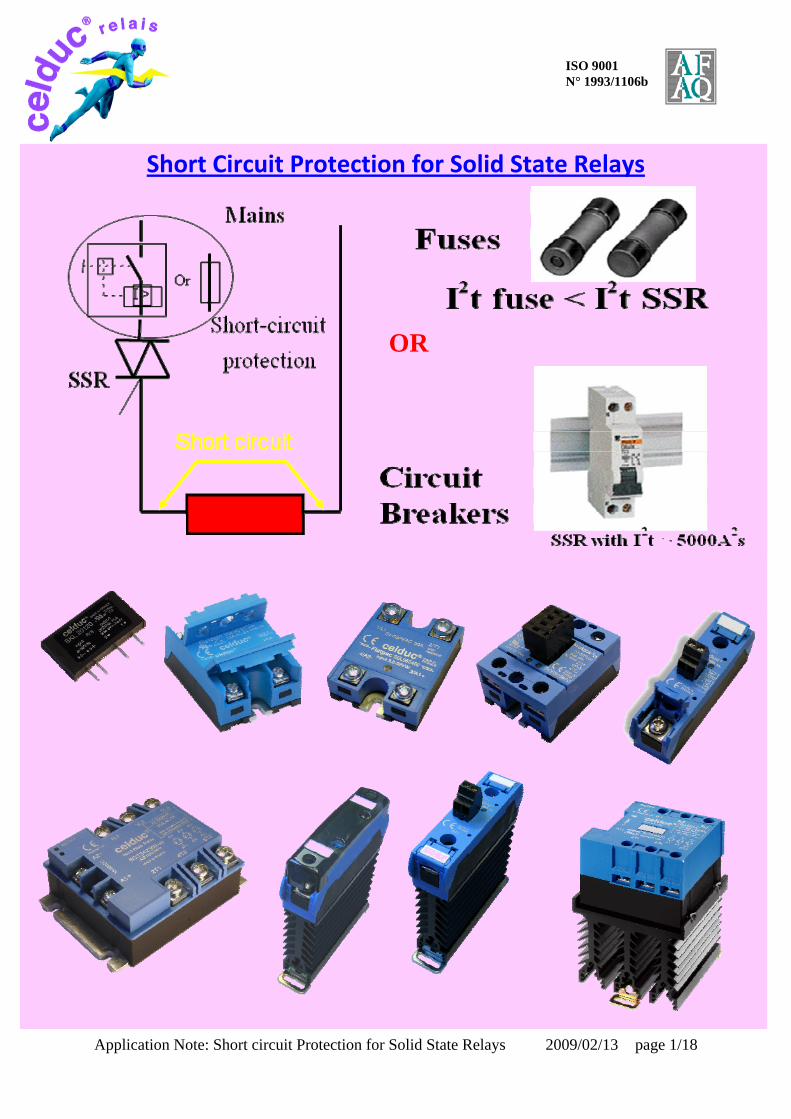
Short Circuit Protection for Solid State Relays

Application Note: Short circuit Protection for Solid State Relays 2009/02/13 page 2/18
ISO 9001 N° 1993/1106b
SUMMURY
I‐ Coordination with short‐circuit protective devices page 3
II‐ Protection with fuses I2t of celduc SSR range and type of fuses page 4 Fast fuses choice page 5 Fast fuses in AC‐51 applications page 6 General purposes fuses choice page 7 AC‐53 applications and aM fuses choice page 8 celduc tests reports in FERRAZ laboratory page 9
III‐ Protection with Miniature Circuit Breakers page 10 Tripping curves page 11 MCB with curve Z choice page 12 MCB with curve K choice page 13 Others MCB : B, C curves page 14 AC‐53 applications and motor protective MCB page 15 Celduc tests in ABB laboratory with certificate page 16
IV‐ Other loads ( Infrared Lamps) page 17
V‐ Advices in case of short circuit page 18

Application Note: Short circuit Protection for Solid State Relays 2009/02/13 page 3/18
ISO 9001 N° 1993/1106b
I‐ Coordination with short‐circuit protective devices
According IEC60947‐4‐x, 2 types of coordination are allowed, type 1 or type 2.
‐ Coordination Type 1 requires that, under short‐circuit conditions, the device shall cause no danger to persons or to the installation and may not be suitable for further service without repair and replacement of parts.
For loads where the risk of short circuit is low, coordination Type 1 can be used. In this case, the SSR is chosen in compliance with the load and the protection is chosen to protect the installation. But in case of short‐circuit, the SSR can be in short‐circuit and must be replaced for further service.
‐ Coordination Type 2 requires that, under short‐circuit conditions, the device shall cause no danger to persons or to the installation and shall be suitable for further use.
For loads where the risk of short circuit is more important, coordination Type 2 must be used. In this case, the SSR is chosen in compliance with the load and the protection device to have the right protection for the installation and the SSR. That means the protection device must react before the SSR is damaged. In case of short circuit, the SSR will be correctly protected and will be suitable for further use.

Application Note: Short circuit Protection for Solid State Relays 2009/02/13 page 4/18
ISO 9001 N° 1993/1106b
II‐ Protection with fuses
Type 1 coordination: Use standard fuse to protect the installation. In case of short circuit on the load, SSR can be damaged and must be replaced. Type 2 coordination: Use a fuse with I2t fuse < I2t SSR celduc SSR range. Thanks to High performances Power thyristors (TMS2 technology) , celduc has got the higher I2t values of the market ( > 20000A2s for 125A SSRs) Nominal current
12A 25A 35A 50A 75A 95A 125A
I2t min (A2s)
72 312 800 1500 5000 11250 20000
I2t typ (A2s)
128 600 1250 2500 7200 14400 24000
To have a correct margin with type 2 coordination, general rule is:
I2t fuse < ½ I2t typ of the SSR celduc make lots of tests in FERRAZ laboratory. Fuses specifications are given at the worst conditions means at maximum voltage, with a defined prospective short circuit current. Some coefficients can be applied to take voltage, …. into account. For more details contact your fuse supplier. For fuses current rating selection an important point is the fuse life‐time. For this reason the fuse current must have a good margin in compliance with the nominal current of the application. Depending on the load, and inrush current of the load, different fuses are possible.
‐ General use ( with fast , medium and time lag models) ‐ Fuses for semi‐conductors (“GR” or “UR” models) ‐ Fuses for motor protection : “aM” types

Application Note: Short circuit Protection for Solid State Relays 2009/02/13 page 5/18
ISO 9001 N° 1993/1106b
Examples with FERRAZ FAST fuses
(tested with celduc SSRs in FERRAZ laboratory)
Compare Total I2t of the fuse given at Umax and I2t of the SSR (page 4) With lower voltage, I2t of the fuse will be lower: A multiplier coefficient K can be applied with the voltage ( see fig 1)
Example: gRC50 14x51 : Total I2t @ 690VRMS = 2250A2s In case of using at 400VRMS, corrector coefficient K = 0.6 I2t becomes 1350A2s
Fig 1

Application Note: Short circuit Protection for Solid State Relays 2009/02/13 page 6/18
ISO 9001 N° 1993/1106b
AC‐51 Applications (Heating applications)
Fast fuse protection coordination type 2
Examples of choice Load current
<8A <15A <25A <30A <55A <70A <90A
SSR nominal current
12A 25A 35A 50A 75A 95A 125A
I2t of SSR (A2s)
72 312 800 1500 5000 11250 20000
Example of fuse from FERRAZ
gRC12 gRC20 gRC32 gRC40 gRC63 gRC80 URD125
I2t of the Fuse (A2s) with 100KA @690VAC (*)
65 175 550 1210 2460 5565 14000
(*): at lower short circuit prospective current and lower Voltage: I2t of the fuse will be lower According curve I2t of the fuse at 400VAC K coefficient will be apply = 0.6
Similar fuses are available by other fuses manufacturers.

Application Note: Short circuit Protection for Solid State Relays 2009/02/13 page 7/18
ISO 9001 N° 1993/1106b
Examples with General fuses
A correct protection can be made under the condition of a correct coordination between the I2t of the fuse and the I2t of the SSR.
Example : with a 20A fuse and a 50A SSR (min I2t 1500A2s/typ 2500A2s) the protection is correct for a coordination type 2 and a voltage of 400V ( black limit)

Application Note: Short circuit Protection for Solid State Relays 2009/02/13 page 8/18
ISO 9001 N° 1993/1106b
AC‐53 Applications (Motors applications)
According IEC60947‐4‐x, starting current Ia must be 8 x Ie (nominal current of the motor) during Ta = 1.6 seconds.
In Ferraz Laboratory celduc tested aM fuse size 14 x 51mm
According these curves and tests celduc gives some advices:
Nominal motor current (AC‐53)
< 7A <12A <16A < 23A
Starting current 56A/1.6s 96A/1.6s 128A/1.6s 184A/1.6s SSR 50A 75A 95A 125A Fuse aM 12 aM 20 aM32 aM50
All these tests have been passed with success in FERRAZ laboratory with a prospective current of 100KA and 500 VRMS. On request, celduc can give results with curves

Application Note: Short circuit Protection for Solid State Relays 2009/02/13 page 9/18
ISO 9001 N° 1993/1106b
Examples of tests made in FERRAZ LABORATORY in FRANCE
(report N°13610)
A part of transformer for short circuit test. Short circuit prospective current can reach 100KA
1) Test with a fast fuse gRC 25A 14x51mm
with U = 525VRMS, cos phi =0.4 and a 50A Solid State Relay. Current at the end of pre‐arcing : 874A Prearc I2t : 47A2s and total I2t = 286A2s Prearc time : 0.18ms Total operate time : 2.58ms
SSR stay alive 2) Test with “aM” fuse for motor : am16A
with U = 525VRMS, prospective short circuit current of 106000A ; cos phi =0.19 and a 75A Solid State Relay. Current at the end of pre‐arcing : 4024A Prearc I2t : 657A2s and total I2t = 1858A2s Prearc time : 0.12ms Total operate time : 2.75ms
SSR stay alive
Application Note: Short circuit Protection for Solid State Relays 2009/02/13 page 10/18
ISO 9001 N° 1993/1106b
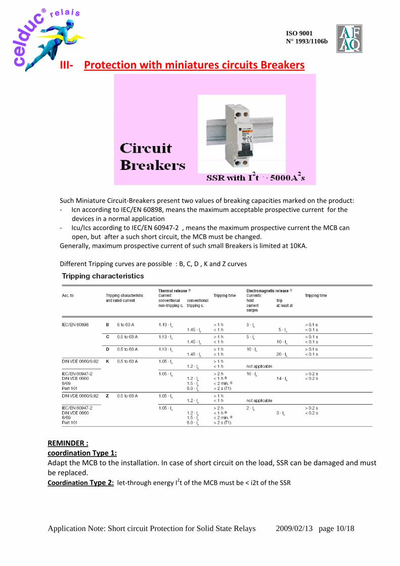
III‐ Protection with miniatures circuits Breakers Such Miniature Circuit‐Breakers present two values of breaking capacities marked on the product: ‐ Icn according to IEC/EN 60898, means the maximum acceptable prospective current for the
devices in a normal application ‐ Icu/Ics according to IEC/EN 60947‐2 , means the maximum prospective current the MCB can
open, but after a such short circuit, the MCB must be changed. Generally, maximum prospective current of such small Breakers is limited at 10KA.
Different Tripping curves are possible : B, C, D , K and Z curves
REMINDER : coordination Type 1: Adapt the MCB to the installation. In case of short circuit on the load, SSR can be damaged and must be replaced. Coordination Type 2: let‐through energy I2t of the MCB must be < i2t of the SSR

Application Note: Short circuit Protection for Solid State Relays 2009/02/13 page 11/18
ISO 9001 N° 1993/1106b
Tripping curves of MCB
Limitation of specific let‐through energy I2t
Tripping of an installation circuit by circuit‐breaker when there is a short‐circuit requires a certain time depending on the characteristics of the circuit‐breaker and the value of the short‐circuit current. During this period of time, part or all of the short‐circuit current flows into the installation; the parameter I2t defines the “specific let‐through energy”, ie. the specific energy that the breaker allows through when there is a short‐circuit current Icc during the tripping time t. In this way, we can determine the capacity of a circuit‐breaker to limit, ie. break high currents up to the rated breaking power of the device, by reducing the peak value of the above‐mentioned currents to a value which is considerably lower than the estimated current. This can be achieved using mechanisms which open very rapidly and have the following advantages:
‐ they limit the thermal and dynamic effects both on the circuit‐breaker and on the protected circuit;
‐ they reduce the dimensions of the current‐limiting circuit‐breaker without reducing breaking capacity;
‐ they considerably reduce ionized gases and sparklers emitted during the short‐circuit and therefore
‐ they avoid the danger of ignition and fires.

Application Note: Short circuit Protection for Solid State Relays 2009/02/13 page 12/18
ISO 9001 N° 1993/1106b
celduc made different tests in ABB laboratory and the conclusion is a short‐circuit protection is possible with Fast miniature circuit Breaker at condition the short circuit prospective current is not too high and with High I2t of SSRs. First tests have been made with S280 Z curves from ABB. Tests results can be sent to customers.
S280 characteristics Z 230/400V let‐through energy
We can see with a 5000A2s SSR, we protect correctly with Z10 and Z16 for Icc > 7kA With Z40 we are limited at 4500A. To reach 10kA it is necessary to use a 95A SSR with 11250A2s With a 1500A2s SSR (50A model) prospective short circuit currents are limited ( 2kA with a Z16)
Conclusion
Z curves specially designed for semiconductors protection are adapted with high I2t celduc SSRs. But Z curve is not very well adapted to load with inrush current. For such loads it is better to use K curves
20 000A2s
11 250A2s
5000A2s
1500A2s

Application Note: Short circuit Protection for Solid State Relays 2009/02/13 page 13/18
ISO 9001 N° 1993/1106b
S280 characteristics K 230/400V let‐through energy
We can see with a 5000A2s SSR, we protect up to 10kA with k10 and K16 Etc……………
Conclusion
K curves is a good alternative to Z curves up to 63A
20 000A2s
11 250A2s
5000A2s
1500A2s

Application Note: Short circuit Protection for Solid State Relays 2009/02/13 page 14/18
ISO 9001 N° 1993/1106b
Other MCBs or curves types are possible.
ABB MOELLER Schneider
Example with a curve B and C from SCHNEIDER
You can see with a 16A MCB curve B or C and a 5000A2s SSR you can reach more than 3KA for short circuit prospective current. By experience, generally the short circuit prospective current on a resistive load rarely exceeds 2kA.

Application Note: Short circuit Protection for Solid State Relays 2009/02/13 page 15/18
ISO 9001 N° 1993/1106b
AC‐53 Applications (Motors applications) For motors applications, the more popular is now to use MOTOR PROTECTIVE CIRCUIT‐ BREAKERS These devices : Motor-protective circuit-breakers are built for coordination type "1" and coordination type "2" Example : PKZM0 from MOELLER In case of Coordination type 2, we have to choose the right model in terms of Breaker with the right thermal current. You have to check the curve I2t according to Prospective current
Example: Motor 4 kW on 400VAC. IAC-53 = 8.5A Starting current Id = 8x In = 68A use with a PKZM0 - 10A. According to this starting current, we have to choose a 95A SSR with an I2t value of 11250A2s. With this protection, you can reach more than 5kA for Iq. By experience, generally the short circuit prospective current on a motor load rarely exceeds 2kA. So SVT868 relays with I2t >11250A2s is a good choice. If necessary you can use SVT869 with I2t >20000A2s, that means a protection up to 12kA

Application Note: Short circuit Protection for Solid State Relays 2009/02/13 page 16/18
ISO 9001 N° 1993/1106b
Examples of tests made in ABB LABORATORY with S280Z celduc has been the first manufacturer to introduce High I2t Solid State Relays. celduc has a large experience with protection by Miniature Circuit‐breakers. First tests have been made in 1995 in ABB laboratory in Italy ( below ABB certificate of test )
Thanks to High performances Power thyristors (TMS2 technology) and the long
collaboration with thyristors dices manufacturers, celduc has got Solid State relays with the highest I2t values of the market ( > 20000A2s for 125A SSRs)

Application Note: Short circuit Protection for Solid State Relays 2009/02/13 page 17/18
ISO 9001 N° 1993/1106b
IV‐ Other Applications (Heating applications with
INFRARED Lamps) Protection coordination type 2
Examples of choice (These values take the lifetime of the fuse into account)
SSR Nominal current
I2t of SSR (A2s)
Long Ia Lamp Ia= 5xIe Ta = 100ms
Short Ia Lamp Ia= 10xIe Ta = 10ms
MCB (breaker) solution
12A 72 Ie max = 3.5A gRC12 14 x51 Ie max = 2A gRC12 14 x51 No solution 25A 312 Ie max = 10A gRC25 14 x51 Ie max = 8A gRC25 14 x51 No solution 35A 800 Ie max = 14A gRC32 14 x51 Ie max = 12A gRC32 14 x51 No solution 50A 1500 Ie max = 20A gRC50 22 x58 Ie max = 18A gRC50 22 x58 No solution 75A 5000 Ie max = 30A gRC63 22 x58 Ie max = 28A gRC63 22 x58 S280K40 95A 11250 Ie max = 35A gRC80 22 x58 Ie max = 32A gRC80 22 x58 S280K50 125A 20000 Ie max = 50A URD135 22x58 Ie max = 45 A URD135 22x58 S280K63

Application Note: Short circuit Protection for Solid State Relays 2009/02/13 page 18/18
ISO 9001 N° 1993/1106b
VI‐ What we have to do after a short circuit.
During a short circuit, you can have some damages on the installation. In first check where the short circuit has been done. After reparation and wirings verification, we advice to test the Solid State relay. Even with a correct protection, the number of short‐circuit for a power semi‐conductor is limited. Some short circuits can limit the life‐time of the components, so generally the number of possible short‐circuit in the life of a power semi‐conductor is maximum 10 times.
Recommended