Networkable Dual Duct VAV ControllerSpecification and Installation Instructions
EVCBM14NIT2S-TRL24-V410-161017-ESL.docx Page | 1
Models EVCBM14NIT2S (Master controller / 2 TRIACs) EVCS14N (Salve controller) TRL24 (Room Sensor: Temp) TRLH24 (Room Sensor: Temp and %RH) TRLG24 (Room Sensor: Temp and CO2) TRLGH24 (Room Sensor: Temp, %RH and CO2)
Description The EVCB Series is a combination controller and thermostat with support for networked communications via the BACnet MS/TP or Modbus protocol. The Networkable Dual Duct VAV Controller is designed for simple and accurate control of any variable air volume box in a number of zone control configurations. Its field configurable algorithms enable versatile implementation of required control sequences.
EVCB Series / TRL24
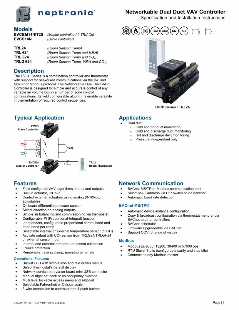
Typical Application
Applications Dual duct
o Cold and hot duct monitoring o Cold and discharge duct monitoring o Hot and discharge duct monitoring o Pressure independant only
Features Field configured VAV algorithms, inputs and outputs Built-in actuator, 70 lb-in Control external actuators using analog (0-10Vdc,
adjustable) On board differential pressure sensor Select direction on analog outputs Simple air balancing and commissioning via thermostat Configurable PI (Proportional-Integral) function Independent, configurable proportional control band and
dead band per ramp Selectable internal or external temperature sensor (10KΩ) Activate output with CO2 sensor from TRLG24/TRLGH24
or external sensor input Internal and external temperature sensor calibration Freeze protection Removable, raising clamp, non-strip terminals
Operational Features Backlit LCD with simple icon and text driven menus Select thermostat’s default display Network service port via on-board mini USB connector Manual night set back or no occupancy override Multi level lockable access menu and setpoint Selectable Fahrenheit or Celsius scale 3-wire connection to controller and 4 push buttons
Network Communication BACnet MS/TP or Modbus communication port Select MAC address via DIP switch or via network Automatic baud rate detection
BACnet MS/TP®
Automatic device instance configuration Copy & broadcast configuration via thermostat menu or via
BACnet to other controllers BACnet scheduler Firmware upgradeable via BACnet Support COV (change of value)
Modbus
Modbus @ 9600, 19200, 38400 or 57600 bps RTU Slave, 8 bits (configurable parity and stop bits) Connects to any Modbus master
EVCBM Master Controller
EVCS Slave Controller
TRL2 Room Thermostat
3 wires
Networkable Dual Duct VAV ControllerSpecification and Installation Instructions
www.neptronic.com EVCBM – Dual Duct Page | 2
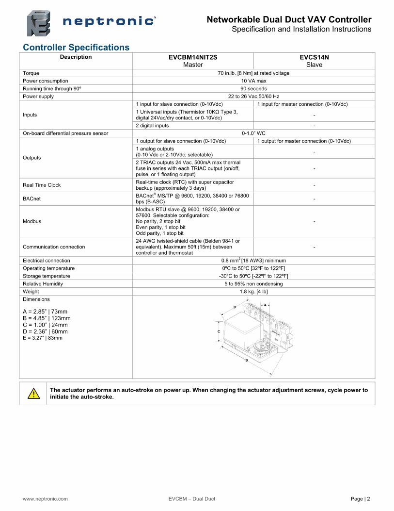
Controller Specifications Description EVCBM14NIT2S
Master EVCS14N
Slave Torque 70 in.lb. [8 Nm] at rated voltage Power consumption 10 VA max
Running time through 90º 90 seconds
Power supply 22 to 26 Vac 50/60 Hz
Inputs
1 input for slave connection (0-10Vdc) 1 input for master connection (0-10Vdc)
1 Universal inputs (Thermistor 10KΩ Type 3, digital 24Vac/dry contact, or 0-10Vdc)
-
2 digital inputs -
On-board differential pressure sensor 0-1.0” WC
Outputs
1 output for slave connection (0-10Vdc) 1 output for master connection (0-10Vdc)
1 analog outputs (0-10 Vdc or 2-10Vdc; selectable)
-
2 TRIAC outputs 24 Vac, 500mA max thermal fuse in series with each TRIAC output (on/off, pulse, or 1 floating output)
-
Real Time Clock Real-time clock (RTC) with super capacitor backup (approximately 3 days)
-
BACnet BACnet® MS/TP @ 9600, 19200, 38400 or 76800 bps (B-ASC)
-
Modbus
Modbus RTU slave @ 9600, 19200, 38400 or 57600. Selectable configuration: No parity, 2 stop bit Even parity, 1 stop bit Odd parity, 1 stop bit
-
Communication connection 24 AWG twisted-shield cable (Belden 9841 or equivalent). Maximum 50ft (15m) between controller and thermostat
-
Electrical connection 0.8 mm2 [18 AWG] minimum
Operating temperature 0ºC to 50ºC [32ºF to 122ºF]
Storage temperature -30ºC to 50ºC [-22ºF to 122ºF]
Relative Humidity 5 to 95% non condensing
Weight 1.8 kg. [4 lb]
Dimensions A = 2.85” | 73mm B = 4.85” | 123mm C = 1.00” | 24mm D = 2.36” | 60mm E = 3.27” | 83mm
The actuator performs an auto-stroke on power up. When changing the actuator adjustment screws, cycle power to initiate the auto-stroke.
C
A
B
D
Networkable Dual Duct VAV ControllerSpecification and Installation Instructions
www.neptronic.com EVCBM – Dual Duct Page | 3
Thermostat Specifications Description TRL24 / TRLH24 / TRLG24 / TRLGH24
Temperature Sensor
Setpoint range 10ºC to 40ºC [50ºF to 104ºF]
Control accuracy Temperature: ±0.4ºC [0.8ºF]
Display resolution ±0.1ºC [0.2ºF]
CO2 Sensor (TRLG24 / TRLGH24 only)
Operating principle Self-calibrating, Non-Dispersive Infrared (NDIR)
Sensor Range 0 to 2000 ppm
Setpoint range 100 to 2000 ppm
Accuracy ±30 ppm ±3% of reading
Response time 2 minutes by 90%
Display resolution 1 ppm
Humidity Sensor (TRLH / TRLGH24 only)
Sensor range 5 to 100%RH
Display resolution 0.1%
Electrical connection 3 wires to EVCB controller and 2 wires to BACnet/Modbus network | 0.8 mm2 [18 AWG] minimum
Network service port Mini USB connector
Power supply 24Vac or 24Vdc
Power consumption 1VA
Operating temperature 0ºC to 50ºC [32ºF to 122ºF]
Storage temperature -30ºC to 50ºC [-22ºF to 122ºF]
Relative humidity 5 to 95 % non condensing
Enclosure protection IP 30 (EN 60529)
Weight 120 g. [0.25 lb]
Dimensions
A = 2.85” | 73mm B = 4.85” | 123mm C = 1.00” | 24mm D = 2.36” | 60mm E = 3.27” | 83mm
LCD Interface
Cooling ONA: Automatic
Communication Status
Alarm status
Heating ONA: Automatic
Menu Locked
Energy saving mode (NSB or Occupancy)
Fan ON A: Automatic
Programming mode (Technician setting)
Percentage of humidity
or
ºC: Celsius scale ºF: Fahrenheit scale
Wiring We strongly recommend that all Neptronic products be wired to a separate grounded transformer and that transformer shall service only Neptronic products. This precaution will prevent interference with, and/or possible damage to incompatible equipment.
A
B
C
DE
ºF / º C
CF
%RH
MO TU WE TH FR SA SU
AM PM
....
%RH
C F
Networkable Dual Duct VAV ControllerSpecification and Installation Instructions
www.neptronic.com EVCBM – Dual Duct Page | 4
DS1 DIP SwitchThe 8 DIP switches represent a binary logic to calculate the MAC address. Default = all OFF
TB
1T
B3
TB
2T
B4
TB
5T
B6
Po
we
rS
tatu
s
ON 1 2
3 4
5 6
7 8
DS
1
TB
7
INT
E
XT
JP1
Room Thermostat
(TRL)
Optional: connect to enable service port
32
AI2
COM
1 analog input – (AI2 config.)
External temp, normally cool/heat, setpoint air flow, CO2, air supply temp
32
AO2
COM
1 analog output (AO2 config.)
Cool ramp 1 or 2, heat ramp 1 or 2, CO2
32
1
DI2
DI1
COM
2 digital inputs (config.)
DI2: Override, normally cool/heatDI1: OCC open/close, NSB open/close
32
1
COM
24Vac input (TO2/TO1)
TO1
4
TO22 TRIAC outputs (config.)
Cool 1 or 2, heat 1 or 2, CO2
On/Off (config close/open percent)Floating (config float time)Pulse (heat only)Direct or reverse
32
1
Data
COM
Pwr
32
1
COM
A+ (in)
B- (in)
54
A+ (out)
B- (out) To otherBACnet devices
Mode Selector JumperRUN = Operation ModePGM = Programming Mode
High Total Pressure
Low Static Pressure
TX
DR
XD
JP3
E
OL
JP1 (TO1 / TO2 input voltage)INT = 24Vac supplied internally by TB1EXT = Apply 24Vac to pin 1 of TB2
TB
1T
B4
TB
5
Po
we
r
2
COM
2
COM
31
24Vac
COM
Power Input
24Vac
Power On = 24Vac applied to TB1
EVCBM14NIT2S (Master)
EVCS14N (Slave)
3
AO2
1AI1
1
AO1
1
AI1
XFO
LineVoltage
L
N
24Vac3
24Vac
1
COM
4
24Vac
2
COM
4
24Vac
2
COM
MA
ST
ER
SL
AV
ETB1
PG
MR
UN
1234567
BACnetServicePort
32
1
Data
COM
Pwr
Important:Use the same transformer for both the Master and Slave.
JP3 (End of line)None = No end of line120 Ohms = Last node on network
TXD Flash transmitting data via network
RXD Flashreceiving data via network
Power On 24Vac applied to TB1
Status Flash communicating via thermostat
Networkable Dual Duct VAV ControllerSpecification and Installation Instructions
www.neptronic.com EVCBM – Dual Duct Page | 5
BACnet or Modbus Address DIP Switch (DS1) MAC address for communication, are selectable by DIP switch using binary logic. If you do not change device instance in program mode, it will be automatically modified according to the MAC address.
Note: Avoid using addresses above 246 when selecting Modbus MAC address.
MAC Address DS.1 = 1 DS.2 = 2 DS.3 = 4 DS.4 = 8 DS.5 = 16 DS.6 = 32 DS.7 = 64 DS.8 = 128 Default Device Instance
0 OFF OFF OFF OFF OFF OFF OFF OFF 153000
1 ON OFF OFF OFF OFF OFF OFF OFF 153001
2 OFF ON OFF OFF OFF OFF OFF OFF 153002
3 ON ON OFF OFF OFF OFF OFF OFF 153003
4 OFF OFF ON OFF OFF OFF OFF OFF 153004
… … … … … … … … … …
126 OFF ON ON ON ON ON ON OFF 153126
127 ON ON ON ON ON ON ON OFF 153127
* Slave addresses available by setting DS.8 to ON
Mounting Instructions CAUTION: Remove power to avoid a risk of malfunction.
A. Remove the captive screw that’s holding the base and the front cover of the unit together. B. Lift the front cover of the unit to separate it from the base. C. Pull all wires through the holes in the base. D. Secure the base to the wall using wall anchors and screws (supplied). Make the appropriate connections. E. Mount the control module on the base and secure using the screw.
A
EDCB
Networkable Dual Duct VAV Controller Specification and Installation Instructions
www.neptronic.com EVCBM – Dual Duct Page | 6
Pressure & Inputs – Menu (1 of 4)
Main Menu
PrSs (Pressure)
rMp (Ramps)
NET (Network)
HrS (Time & Date)
tot (Total)
Select Pressur 2
LOC (Local)
Setc (Settings)
Mot (Motor)
tMp (Temperature)
OutP (Outputs)
InPt (Inputs)
= scroll menu items
= scroll menu items
Main Menu Sub Menu Configuration
YES (enabled)
Airflow Cnstant Option
NO (disabled)
Airflow Dead Band Mix
0.0°C / 0.0°F
BV.49
BV.48 AV.128
*** You must press the button to save any changes *** *** Pressing the button returns to the previous step without saving ***
Go to “InPt"
Go to “InPt"
OPt (Options)
This setting affects only the pressure sensor of the slave unit EVCS14N. The pressure sensor of the master unit cannot be modified.
DI2
DI1
AI2
Config Input
AI1
= scroll menu items
= select / set value
nSbc (night set back closed)
nSbo (night set back open)
OCCc (occupancy closed)
OCCo (occupancy open)
NSB-OCC Contact
OFF Go to “DI2"
NSB Overide delay Min
120 min (0-180)
No OCC Overide Delay Min
120 min (0-180)
Off
NSB Mode
StP (setpoint)
No OCC Heating setpnt
16°C / 61°F
No OCC Cooling setpnt
28°C / 82°FGo to “DI2"
NSB Heating setpnt
16°C / 61°F
NSB Cooling setpnt
28°C / 82°F
Go to “DI2"
DI2 Signal Type
NC (normally closed)OVH2 (override heat 2)
OVH1 (override heat 1)
Ovrd (override all)
OFF
OVHt (override all heat)
= select / set value
DI2 Delay Seconds
120 (0-3600)
DI2 Contact
NO (normally open)
Go to “OutP"
Go to “OutP"
DI1
DI2
ASt (Air supply temp sensor)
CO2 (carbon dioxide)
AI2 Signal Type
EtS (external temp sensor)
OFF (disabled)
= select / set value
AI2
CO2 Maximum Range
2000 ppm
CO2 Setpnt
800 ppm
Go to “DI1"
OPEn
NSB Motor Mode
Auto
AV.140
AV.61
AV.60
MSV.2
MSV.10
MSV.14
AV.141
AV.19
BV.20
AV.18
AV.19 AV.18
MSV.36
AV.64
BV.36
Reserved for slave connection
Go to “DI1"
YES
CO2 DISPLAY
NO
BV.65
Appears only if using TRL or TRLHFor TRLG and TRLGH go to “Opt” menu.
To display CO2 without generating an alarm, use a setpoint higher than 2000ppm or the CO2 Maximum Range (highest of the 2).
When set to YES, the unit will not display the time when in Operation Mode
Networkable Dual Duct VAV Controller Specification and Installation Instructions
www.neptronic.com EVCBM – Dual Duct Page | 7
Outputs – Menu (2 of 4)
PrSs (Pressure)
TO1 DIR-REV
DIR (direct)
REV (reverse)
PuLs (pulsed) *
AO1
AO2
FLt (floating)
CO2 (carbon dioxide)
Hr2 (heating ramp 2)
Hr1 (heating ramp 1)
TO2
Output Config
TO1
Cr2 (cooling ramp 2)
Cr1 (cooling ramp 1)
TO1 Ramp
OFF
= scroll menu items
= select / set value
TO1 Close Percent
40% (15-80%)TO1 Signal Type
OnOf (on/off)
Go to “TO2"
* = Only if Hr1 or Hr2 is selected
TO1-TO2 Floating Time in Sec
100 sec (15 to 250 secs)
TO1 Open Percent
0% [0-(TO1 cls pos-4)]
Go to “TO2"
TO2 DIR-REV
DIR (direct)
REV (reverse)
PuLs (pulsed)
TO2 Close Percent
40% (15-80%)TO2 Signal Type
OnOf (on/off)
Go to “AO2"
TO2 Open Percent
0% [0-(TO2 cls pos-4)]
Go to “AO2
"
Main Menu Sub Menu Configuration
rMp (Ramps)
NET (Network)
HrS (Time & Date)
Setc (Settings)
Mot (Motor)
tMp (Temperature)
OutP (Outputs)
= scroll menu items
TO1-TO2 DIR-REV
DIR (direct)
REV (reverse)
Go to “AO2"
MSV.25
MSV.26
MSV.28
AV.77
AV.75
AV.79
AV.78
BV.32
BV.30
AV.80
BV.33
If CO2 was selected
TO1
CO2 (carbon dioxide)
Hr2 (heating ramp 2)
Hr1 (heating ramp 1)
Cr2 (cooling ramp 2)
Cr1 (cooling ramp 1)
TO2 Ramp
OFF
= select / set value
MSV.27 TO2
*** You must press the button to save any changes *** *** Pressing the button returns to the previous step without saving ***
InPt (Inputs)
Main Menu*
*
**
**
* **
**
**
* *
* * *
Reserved for slave connection*
OPt (Options)
AO2 DIR-REV
DIR (direct)
REV (reverse)
CO2 (carbon dioxide)
Hr2 (heating ramp 2)
Hr1 (heating ramp 1)
Cr2 (cooling ramp 2)
Cr1 (cooling ramp 1)
AO2 Ramp
OFF
= select / set value
AO2 Minimum Voltage
0.0 Vdc
Go to “tmp"
AO2 Maximum Voltage
10.0 Vdc
Go to “tmp"
MSV.22
AV.72 AV.73
BV.26
AO2
*
*
Networkable Dual Duct VAV Controller Specification and Installation Instructions
www.neptronic.com EVCBM – Dual Duct Page | 8
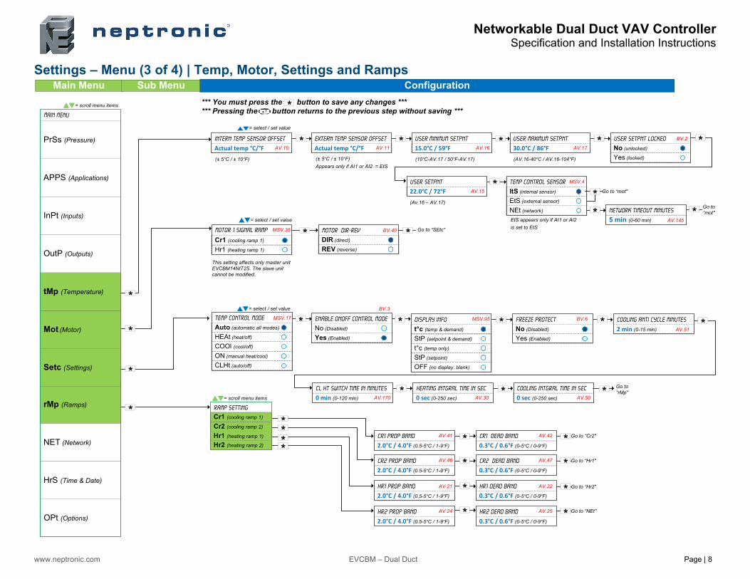
Settings – Menu (3 of 4) | Temp, Motor, Settings and Ramps
Main Menu
APPS (Applications)
PrSs (Pressure)
CLHt (auto/off) OFF (no display: blank)
ON (manual heat/cool)
NEt (network)
Main Menu
= select / set value
Intern Temp Sensor Offset
Actual temp °C/°F Extern Temp Sensor Offset
Actual temp °C/°F User Minimum Setpnt
15.0°C / 59°FUser Maximum Setpnt
30.0°C / 86°FUser Setpnt Locked
No (unlocked)
Yes (locked)
User Setpnt
22.0°C / 72°FTemp Control Sensor
ItS (internal sensor)
EtS (external sensor)
Go to “mot"
Go to “mot"Network timeout Minutes
5 min (0-60 min)
(Av.16 – AV.17)
(AV.16-40°C / AV.16-104°F)(10°C-AV.17 / 50°F-AV.17)(± 5°C / ± 10°F)
Appears only if AI1 or AI2 = EtS
COOl (cool/off)
Temp Control Mode
Auto (automatic all modes)
HEAt (heat/off)
= select / set value
Enable onoff Control Mode
No (Disabled)
Yes (Enabled)
StP (setpoint)
t°c (temp only)
Display Info
t°c (temp & demand)
StP (setpoint & demand)
Freeze Protect
No (Disabled)
Yes (Enabled)
Cooling anti cycle minutes
2 min (0-15 min)
Cl Ht Switch Time in Minutes
0 min (0-120 min)
Heating Intgral time in Sec
0 sec (0-250 sec)
Cooling Intgral time in Sec
0 sec (0-250 sec)
Go to “rMp"
Ramp Setting
= scroll menu items
Sub Menu Configuration
rMp (Ramps)
NET (Network)
HrS (Time & Date)
Setc (Settings)
Mot (Motor)
tMp (Temperature)
OutP (Outputs)
InPt (Inputs)
= scroll menu items
Hr1 (heating ramp 1)
Motor 1 Signal Ramp
= select / set value
Motor DIR-REV
DIR (direct)
REV (reverse)
Cr1 (cooling ramp 1)
EtS appears only if AI1 or AI2
is set to EtS
AV.10
(± 5°C / ± 10°F)
MSV.35
MSV.17
AV.11
BV.40
BV.3
AV.170
AV.16
AV.15
MSV.95
AV.17
MSV.4
BV.6
AV.30 AV.50
AV.51
AV.145
BV.2
*** You must press the button to save any changes *** *** Pressing the button returns to the previous step without saving ***
Go to “SEtc"
*
*
*
*
*
* * * * *
**
* *
*
* * * * *
* *
*
*
OPt (Options)
This setting affects only master unit EVCBM14NIT2S. The slave unit cannot be modified.
Hr2 (heating ramp 2)
Hr1 (heating ramp 1)
Cr2 (cooling ramp 2)
Cr1 (cooling ramp 1)
CR1 Prop Band
2.0°C / 4.0°F (0.5-5°C / 1-9°F)
CR1 Dead Band
0.3°C / 0.6°F (0-5°C / 0-9°F)
CR2 Prop Band
2.0°C / 4.0°F (0.5-5°C / 1-9°F)
CR2 Dead Band
0.3°C / 0.6°F (0-5°C / 0-9°F)
Hr1 Prop Band
2.0°C / 4.0°F (0.5-5°C / 1-9°F)
Hr1 Dead Band
0.3°C / 0.6°F (0-5°C / 0-9°F)
Go to “Cr2"
Go to “Hr1"
Go to “Hr2"
Hr2 Prop Band
2.0°C / 4.0°F (0.5-5°C / 1-9°F)
Hr2 Dead Band
0.3°C / 0.6°F (0-5°C / 0-9°F)
Go to “NEt"
AV.41
AV.46
AV.21
AV.24
AV.42
AV.47
AV.22
AV.25
****
*
*
*
*
*
*
*
*
Networkable Dual Duct VAV Controller Specification and Installation Instructions
www.neptronic.com EVCBM – Dual Duct Page | 9
Settings – Menu (6 of 6) | Network, Time and Options
CPYc (copy config)
bAC
mOd
Network Config
tYPe (Type)
= scroll menu items
Main Menu Sub Menu Configuration
Network Choice
bAC (BACnet)
mOd (Modbus)
= select / set value
Modbus Auto Baud Rate
No (Manual)
Yes (Automatic)
= select / set value
BACnet Auto Baud Rate
No (Manual)
Yes (Automatic)
= select / set value
= select / set value
Start Address
0 (0-254)
Go to “BACnet Auto Baud Rate"
Go to “Modbus Auto Baud Rate"
If type = bAC, menu contains “tYpe”, “bAC” and “CPYc”
If type = mOd, menu contains “tYpe and “mOd”
Modbus Baud Rate
57.6k (9.6k, 19.2k, 38.4, 57.6k)
Bacnet Baud Rate
76.8k (9.6k, 19.2k, 38.4, 76.8k)
MSTP MAC Address
0 (0-254)
Modifiable only if Auto Baud Rate
set to “No”.
Modifiable only if Auto Baud Rate
set to “No”.
Modifiable only if all DS1 DIP
switches are set to OFF.
0153000
0 (device instance)
Go to “CPYc"MSTP MAX Master
127 (1-127)
OP1s (odd parity, 1 stop bit)
Modbus Comport Config
NP2s (no parity, 2 stop bits)
EP1s (even parity, 1 stop bit)
Modbus Address
1 (1-246)
Modifiable only if all DS1 DIP
switches are set to OFF.
Go to “HrS"
End Address
0 (0-254: max=start + 63)
Confirm Copy Config
No (cancel)
Yes (confirm)
Copy Config
in (in progress)
Go to “HrS"
Copy Config Result
Succeed
Go to “HrS"
= select / set value
Hours
12 (0-23 or 1-12 am/pm)
Minutes
00 (00-59)
Year
15 (15-99)
Set Time Display format
24 (24-hour format)
12 (AM/PM format)
Month
1 (1-12)
Day
1 (1-31)
Go to “OPt"
Main Menu
APPS (Applications)
PrSs (Pressure)
rMp (Ramps)
NET (Network)
HrS (Time & Date)
Setc (Settings)
Mot (Motor)
tMp (Temperature)
OutP (Outputs)
InPt (Inputs)
= scroll menu items
1001
AV.166AV.165
1000
BV.90
AV.167
Local Time Local DateLocal Time
Local DateLocal Date
Refer to Copy Config Annnex for a complete list of messages and error codes.
*** You must press the button to save any changes *** *** Pressing the button returns to the previous step without saving ***
OPt (Options)
CO2 Setpnt
800 ppm
AV.141
ANLg
CO2 Control Source
trL
BV.66
NO
CO2 DISPLAY
YES
BV.65 Go to “PrSs"
NO
DISPLAY Humidty
YES
BV.60
Appears only if using TRLG or TRLGHFor TRL and TRLH go to “InPt” menu.
Appears only if using TRLG or TRLGHFor TRL and TRLH go to “InPt” menu.
Appears only if using TRLG or TRLGH Appears only if using TRLH or TRLGH
To display CO2 without generating an alarm, use a setpoint higher than 2000ppm or the CO2 Maximum Range (highest of the 2).
When set to YES, the unit will not display the time when in Operation Mode
Networkable Dual Duct VAV ControllerSpecification and Installation Instructions
www.neptronic.com EVCBM – Dual Duct Page | 10
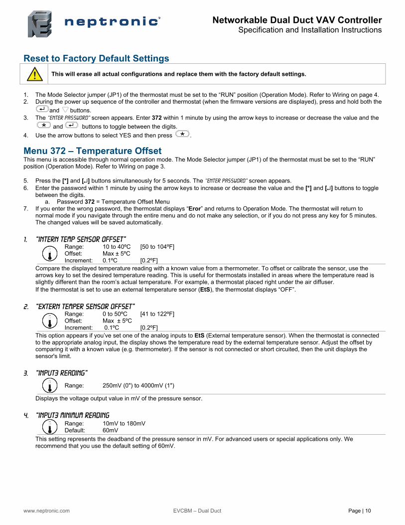
Reset to Factory Default Settings
This will erase all actual configurations and replace them with the factory default settings.
1. The Mode Selector jumper (JP1) of the thermostat must be set to the “RUN” position (Operation Mode). Refer to Wiring on page 4. 2. During the power up sequence of the controller and thermostat (when the firmware versions are displayed), press and hold both the
and buttons. 3. The “Enter Password” screen appears. Enter 372 within 1 minute by using the arrow keys to increase or decrease the value and the
and buttons to toggle between the digits.
4. Use the arrow buttons to select YES and then press .
Menu 372 – Temperature Offset This menu is accessible through normal operation mode. The Mode Selector jumper (JP1) of the thermostat must be set to the “RUN” position (Operation Mode). Refer to Wiring on page 3. 5. Press the [*] and [] buttons simultaneously for 5 seconds. The “Enter Password” screen appears. 6. Enter the password within 1 minute by using the arrow keys to increase or decrease the value and the [*] and [] buttons to toggle
between the digits. a. Password 372 = Temperature Offset Menu
7. If you enter the wrong password, the thermostat displays “Eror” and returns to Operation Mode. The thermostat will return to normal mode if you navigate through the entire menu and do not make any selection, or if you do not press any key for 5 minutes. The changed values will be saved automatically.
1. “Intern Temp Sensor Offset”
Range: Offset: Increment:
10 to 40ºC [50 to 104ºF] Max ± 5ºC 0.1ºC [0.2ºF]
Compare the displayed temperature reading with a known value from a thermometer. To offset or calibrate the sensor, use the arrows key to set the desired temperature reading. This is useful for thermostats installed in areas where the temperature read is slightly different than the room’s actual temperature. For example, a thermostat placed right under the air diffuser. If the thermostat is set to use an external temperature sensor (EtS), the thermostat displays “OFF”.
2. “Extern Temper Sensor Offset”
Range: Offset: Increment:
0 to 50ºC [41 to 122ºF] Max ± 5ºC 0.1ºC [0.2ºF]
This option appears if you’ve set one of the analog inputs to EtS (External temperature sensor). When the thermostat is connected to the appropriate analog input, the display shows the temperature read by the external temperature sensor. Adjust the offset by comparing it with a known value (e.g. thermometer). If the sensor is not connected or short circuited, then the unit displays the sensor's limit.
3. “Input3 Reading”
Range: 250mV (0") to 4000mV (1")
Displays the voltage output value in mV of the pressure sensor.
4. “Input3 Minimum Reading
Range: Default:
10mV to 180mV 60mV
This setting represents the deadband of the pressure sensor in mV. For advanced users or special applications only. We recommend that you use the default setting of 60mV.
Networkable Dual Duct VAV Controller Specification and Installation Instructions
www.neptronic.com EVCBM – Dual Duct Page | 11
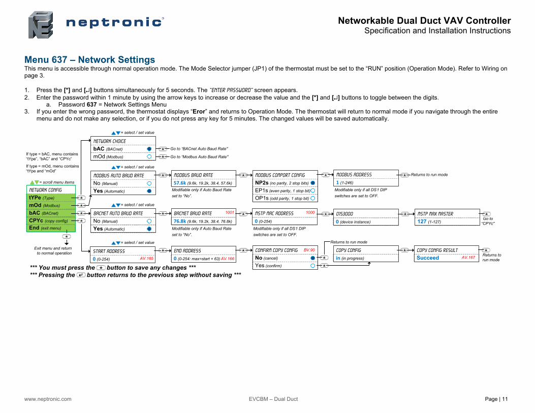
Menu 637 – Network Settings This menu is accessible through normal operation mode. The Mode Selector jumper (JP1) of the thermostat must be set to the “RUN” position (Operation Mode). Refer to Wiring on page 3. 1. Press the [*] and [] buttons simultaneously for 5 seconds. The “Enter Password” screen appears. 2. Enter the password within 1 minute by using the arrow keys to increase or decrease the value and the [*] and [] buttons to toggle between the digits.
a. Password 637 = Network Settings Menu 3. If you enter the wrong password, the thermostat displays “Eror” and returns to Operation Mode. The thermostat will return to normal mode if you navigate through the entire
menu and do not make any selection, or if you do not press any key for 5 minutes. The changed values will be saved automatically.
End (exit menu)
CPYc (copy config)
bAC (BACnet)
mOd (Modbus)
Network Config
tYPe (Type)
= scroll menu items
Network Choice
bAC (BACnet)
mOd (Modbus)
= select / set value
Modbus Auto Baud Rate
No (Manual)
Yes (Automatic)
= select / set value
BACnet Auto Baud Rate
No (Manual)
Yes (Automatic)
= select / set value
= select / set value
Start Address
0 (0-254)
If type = bAC, menu contains “tYpe”, “bAC” and “CPYc”
If type = mOd, menu contains “tYpe and “mOd”
Modbus Baud Rate
57.6k (9.6k, 19.2k, 38.4, 57.6k)
Bacnet Baud Rate
76.8k (9.6k, 19.2k, 38.4, 76.8k)
MSTP MAC Address
0 (0-254)
Modifiable only if Auto Baud Rate
set to “No”.
Modifiable only if Auto Baud Rate
set to “No”.
Modifiable only if all DS1 DIP
switches are set to OFF.
0153000
0 (device instance)Go to
“CPYc"
MSTP MAX Master
127 (1-127)
OP1s (odd parity, 1 stop bit)
Modbus Comport Config
NP2s (no parity, 2 stop bits)
EP1s (even parity, 1 stop bit)
Modbus Address
1 (1-246)
Modifiable only if all DS1 DIP
switches are set to OFF.
Returns to run mode
End Address
0 (0-254: max=start + 63)
Confirm Copy Config
No (cancel)
Yes (confirm)
Copy Config
in (in progress)
Returns to run mode
Copy Config Result
Succeed
1001
AV.166AV.165
1000
BV.90
AV.167
Exit menu and return to normal operation
Go to “BACnet Auto Baud Rate"
Go to “Modbus Auto Baud Rate"
Returns to run mode
*** You must press the button to save any changes *** *** Pressing the button returns to the previous step without saving ***
Networkable Dual Duct VAV Controller Specification and Installation Instructions
www.neptronic.com EVCBM – Dual Duct Page | 12
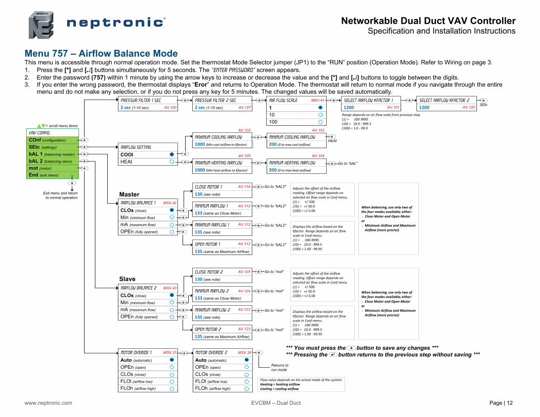
Menu 757 – Airflow Balance Mode This menu is accessible through normal operation mode. Set the thermostat Mode Selector jumper (JP1) to the “RUN” position (Operation Mode). Refer to Wiring on page 3. 1. Press the [*] and [] buttons simultaneously for 5 seconds. The “Enter Password” screen appears. 2. Enter the password (757) within 1 minute by using the arrow keys to increase or decrease the value and the [*] and [] buttons to toggle between the digits. 3. If you enter the wrong password, the thermostat displays “Eror” and returns to Operation Mode. The thermostat will return to normal mode if you navigate through the entire
menu and do not make any selection, or if you do not press any key for 5 minutes. The changed values will be saved automatically.
Air Flow Scale Select Airflow Kfactor 1
1200
End (exit menu)
mot (motor)
bAL 1 (balancing master)
SEtc (settings)
VAV Config
COnf (configuration)
= scroll menu items
Pressur Filter 1 Sec
2 sec (1-10 sec) 1
10
100
Maximum Cooling Airflow
1000 (Min cool airflow to Kfactor)Airflow Setting
COOl
HEAt
Minimum Cooling Airflow
200 (0 to max cool airflow)
Maximum Heating Airflow
1000 (Min heat airflow to Kfactor)
Minimum Heating Airflow
200 (0 to max heat airflow)
Go to “bAL"
Airflow Balance 1
CLOs (close)
Min (minimum flow)
mA (maximum flow)
OPEn (fully opened)
Close Motor 1
130 (see note)
Minimum Airflow 1
133 (same as Close Motor)
Maximum Airflow 1
135 (see note)
Open Motor 1
135 (same as Maximum Airflow)
Motor Overide 1
Auto (automatic)
OPEn (open)
CLOs (close)
FLOl (airflow low)
FLOh (airflow high)
Exit menu and return to normal operation
Range depends on air flow scale from previous step: (1) = 100‐9995(10) = 10.0 ‐ 999.5(100) = 1.0 ‐ 99.9
Adjusts the offset of the airflow reading. Offset range depends on selected air flow scale in Conf menu. (1) = +/‐500(10) = +/‐50.0(100) = +/‐5.00
Displays the airflow based on the Kfactor. Range depends on air flow scale in Conf menu:.(1) = 100‐9995(10) = 10.0 ‐ 999.5(100) = 1.00 ‐ 99.95
AV.100
MSV.41
AV.101
AV.103 AV.102
AV.105 AV.104
MSV.42
MSV.37
AV.114
AV.113
AV.112
AV.112
HEAt
Returns to run mode
Go to “bAL2"
Go to “bAL2"
Go to “bAL2"
Go to “bAL2"
When balancing, use only two of the four modes available; either: Close Motor and Open Motoror Minimum Airflow and Maximum Airflow (more precise)
*** You must press the button to save any changes *** *** Pressing the button returns to the previous step without saving ***
Airflow Balance 2
CLOs (close)
Min (minimum flow)
mA (maximum flow)
OPEn (fully opened)
Close Motor 2
130 (see note)
Minimum Airflow 2
133 (same as Close Motor)
Maximum Airflow 2
135 (see note)
Open Motor 2
135 (same as Maximum Airflow)
Adjusts the offset of the airflow reading. Offset range depends on selected air flow scale in Conf menu. (1) = +/‐500(10) = +/‐50.0(100) = +/‐5.00
Displays the airflow based on the Kfactor. Range depends on air flow scale in Conf menu:.(1) = 100‐9995(10) = 10.0 ‐ 999.5(100) = 1.00 ‐ 99.95
MSV.43
AV.125
AV.124
AV.123
AV.123
Go to “mot"
Go to “mot"
Go to “mot"
Go to “mot"
When balancing, use only two of the four modes available; either: Close Motor and Open Motoror Minimum Airflow and Maximum Airflow (more precise)
Pressur Filter 2 Sec
2 sec (1-10 sec) AV.127
Select Airflow Kfactor 2
1200 SEtcAV.120
bAL 2 (balancing slave)
Motor Overide 2
Auto (automatic)
OPEn (open)
CLOs (close)
FLOl (airflow low)
FLOh (airflow high)
MSV.38
Returns to run mode
Flow value depends on the actual mode of the system:Heating = heating airflowCooling = cooling airflow
Master
Slave
Networkable Dual Duct VAV ControllerSpecification and Installation Instructions
www.neptronic.com EVCBM – Dual Duct Page | 13
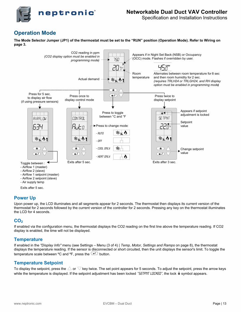
Operation Mode The Mode Selector Jumper (JP1) of the thermostat must be set to the “RUN” position (Operation Mode). Refer to Wiring on page 3.
Power Up Upon power up, the LCD illuminates and all segments appear for 2 seconds. The thermostat then displays its current version of the thermostat for 2 seconds followed by the current version of the controller for 2 seconds. Pressing any key on the thermostat illuminates the LCD for 4 seconds.
CO2 If enabled via the configuration menu, the thermostat displays the CO2 reading on the first line above the temperature reading. If CO2 display is enabled, the time will not be displayed.
Temperature If enabled in the "Display Info" menu (see Settings – Menu (3 of 4) | Temp, Motor, Settings and Ramps on page 8), the thermostat displays the temperature reading. If the sensor is disconnected or short circuited, then the unit displays the sensor's limit. To toggle the temperature scale between ºC and ºF, press the button.
Temperature Setpoint To display the setpoint, press the or key twice. The set point appears for 5 seconds. To adjust the setpoint, press the arrow keys while the temperature is displayed. If the setpoint adjustment has been locked “Setpnt Locked”, the lock symbol appears.
Press to toggle between °C and °F
Actual demand
C
Appears if setpoint adjustment is locked
Change setpoint value
C
Press once to display control mode
Press for 5 sec. to display air flow
(if using pressure sensors)
Exits after 5 sec. Exits after 3 sec.
Press twice to display setpoint
Setpoint valuePress to change mode:
- Auto
- Off
- Cool only
- Heat only
Appears if in Night Set Back (NSB) or Occupancy (OCC) mode. Flashes if overridden by user.
CO2 reading in ppm(CO2 display option must be enabled in
programming mode)
%RH
Room temperature
Alternates between room temperature for 8 sec and then room humidity for 2 sec. (requires TRLH24 or TRLGH24, and RH display option must be enabled in programming mode)
Toggle between : - Airflow 1 (master)- Airflow 2 (slave)- Airflow 1 setpoint (master)- Airflow 2 setpoint (slave)- Air supply temp
Exits after 5 sec.
Networkable Dual Duct VAV ControllerSpecification and Installation Instructions
www.neptronic.com EVCBM – Dual Duct Page | 14
Humidity If enabled in the "Options" menu (see Settings – Menu (6 of 6) | Network, Time and Options on page 9), the thermostat displays the temperature reading for 8 seconds and then displays the humidity reading for 2 seconds. If the sensor is disconnected or short circuited, then the unit displays the sensor's limit.
Airflow and Air Supply Temperature
Press and hold the button for 5 seconds and use the arrow keys to view the “airflow 1” (master), “airflow 2” (slave), “airflow Setpnt 1" (master), “airflow Setpnt 2" (slave), and “air Supply Temp”. After 5 seconds without any action, the thermostat returns to operation mode. The air supply temperature appears only if analog input AI1 or AI2 are configured with the AST option.
Control Mode
To access the Control Mode, press the button. The Control Mode appears for 5 seconds. Press the button to scroll through the following control modes. These options can vary depending on the options selected in "Temp Control Mode" and "Enable OnOff Control Mode". Auto (Automatic Cooling or Heating) Cooling only (on, with cooling symbol) Heating only (on, with heating symbol) OFF (if it is not disabled in Programming Mode)
Night Set Back (NSB) or Occupancy Mode This function is only available if you set DI1 to nSb (Night set back contact) or Occ (occupancy mode). If the DI1 contact is triggered, the thermostat enters NSB or No Occupancy Mode (the symbol appears) and uses the NSB or OCC heating and cooling setpoints. If not locked, you can override the night set back or no occupancy mode for a predetermined period by pressing any of the 4 buttons. During the override period the symbol will flash. If the symbol does not flash, the override period is finished or the night set back or no occupancy override has been locked in programming mode.
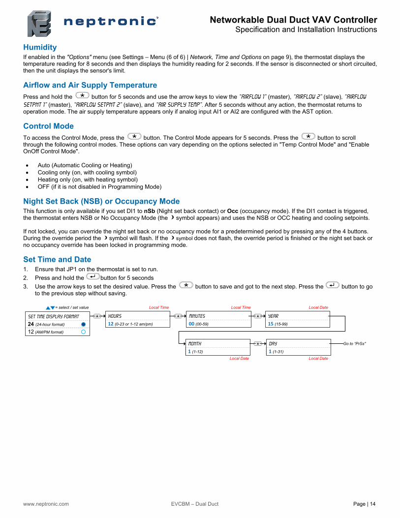
Set Time and Date 1. Ensure that JP1 on the thermostat is set to run.
2. Press and hold the button for 5 seconds
3. Use the arrow keys to set the desired value. Press the button to save and got to the next step. Press the button to go to the previous step without saving.
= select / set value
Hours
12 (0-23 or 1-12 am/pm)
Minutes
00 (00-59)
Year
15 (15-99)
Set Time Display format
24 (24-hour format)
12 (AM/PM format)
Month
1 (1-12)
Day
1 (1-31)
Go to “PrSs"
Local Time Local DateLocal Time
Local DateLocal Date

Notes

400 Lebeau blvd, Montreal, Qc, H4N 1R6, Canada
www.neptronic.com
Toll free in North America: 1-800-361-2308 Tel.: (514) 333-1433 Fax: (514) 333-3163
Customer service fax: (514) 333-1091 Monday to Friday: 8:00am to 5:00pm (Eastern time)
Recommended