Embed Size (px)
Citation preview

A4 Application library CR24 V1.1 EN
Single room applications CR
6.6.05 – Update with applications Dual-duct units, electrical re-heater and radiator heating
Key to IRC application numbering
5.04 Trk
Su
bjec
t to
chan
ges
Layout System - Application - Number -> I R C - V A V - IRC VAV application I R C - V A V - 0 0 1 1 . 0 IRC system VAV variant 0011.0 I R C - V A V - 0 0 1 1 . 1 - sub-variant 0001.1
Key System - Application - Number -> System Application I R C - A I R - IRC Air (damper) - - I R C - V A V - IRC VAV - - I R C - W A T - IRC Water - - I R C - C L C - IRC Chilled/heated ceiling - - I R C - V A R - IRC Various
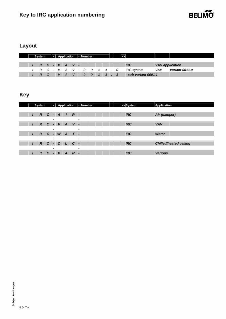
Overview IRC applications
5.04 Trk
Su
bjec
t of c
hang
es
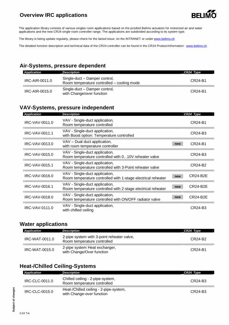
Air-Systems, pressure dependent
Application Description CR24 Type IRC-AIR-0011.0 Single-duct – Damper control,
Room temperature controlled – cooling mode CR24-B1
IRC-AIR-0015.0 Single-duct – Damper control, with Change/over function CR24-B1
VAV-Systems, pressure independent
Application Description CR24 Type IRC-VAV-0011.0 VAV - Single-duct application,
Room temperature controlled CR24-B1
IRC-VAV-0011.1 VAV - Single-duct application, with Boost option: Temperature controlled CR24-B3
IRC-VAV-0013.0 VAV – Dual duct application, with room temperature controller CR24-B1
IRC-VAV-0015.0 VAV - Single-duct application, Room temperature controlled with 0...10V reheater valve CR24-B3
IRC-VAV-0015.1 VAV - Single-duct application, Room temperature controlled with 3-Point reheater valve CR24-B2
IRC-VAV-0016.0 VAV - Single-duct application, Room temperature controlled with 1-stage electrical reheater CR24-B2E
IRC-VAV-0016.1 VAV - Single-duct application, Room temperature controlled with 2-stage electrical reheater CR24-B2E
IRC-VAV-0018.0 VAV - Single-duct application, Room temperature controlled with ON/OFF radiator valve CR24-B2E
IRC-VAV-0111.0 VAV - Single-duct application, with chilled ceiling CR24-B3
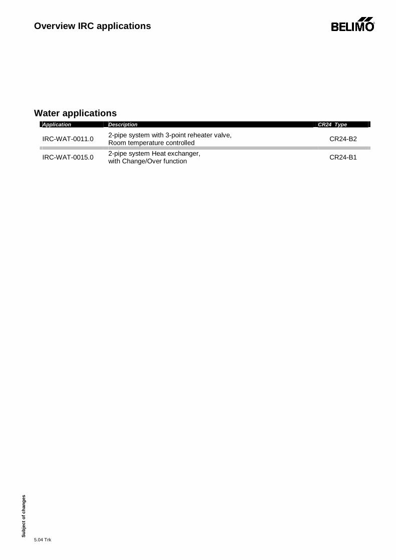
Water applications
Application Description CR24 Type IRC-WAT-0011.0 2-pipe system with 3-point reheater valve,
Room temperature controlled CR24-B2
IRC-WAT-0015.0 2-pipe system Heat exchanger, with Change/Over function CR24-B1
Heat-/Chilled Ceiling-Systems
Application Description CR24 Type IRC-CLC-0011.0 Chilled ceiling - 2-pipe-system,
Room temperature controlled CR24-B3
IRC-CLC-0015.0 Heat-/Chilled ceiling - 2-pipe-system, with Change-over function CR24-B3
The application library consists of various singles room applications based on the proofed Belimo actuators for motorized air and water applications and the new CR24 single room controller range. The applications are subdivided according to its system type. The library is being update regularly, please check for the lasted issue: on the INTRANET or under www.belimo.ch The detailed function description and technical data of the CR24 controller can be found in the CR24 Product-Information: www.belimo.ch
new
new
new
new
Overview IRC applications
5.04 Trk
Su
bjec
t of c
hang
es
Air-Systems, pressure dependent
Application Description CR24 Type IRC-AIR-0011.0 Single-duct – Damper control,
Room temperature controlled – cooling mode CR24-B1
IRC-AIR-0015.0 Single-duct – Damper control, with Change/over function CR24-B1
Air-System, pressure depending
V1.0 5.04 Trk
Su
bjec
t of c
hang
es
IRC-AIR-0011.0
IRC-AIR-0011.0
Single-duct Damper control, Room temperature controlled – cooling mode
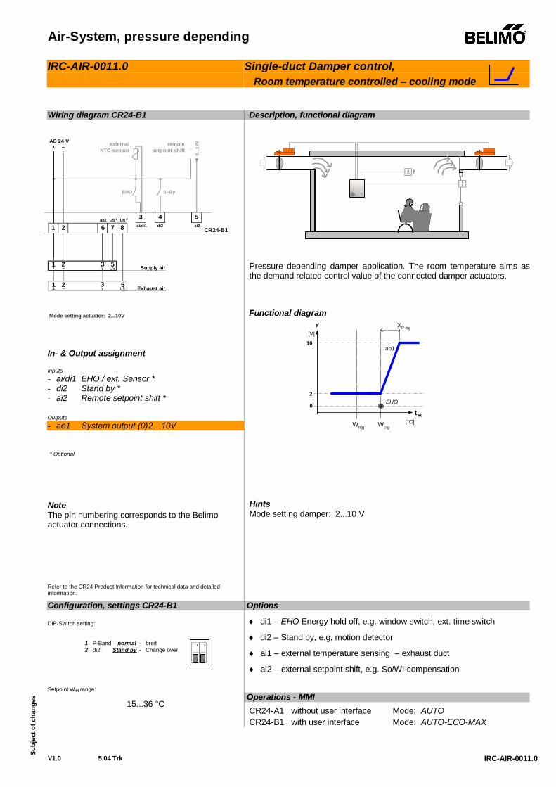
Wiring diagram CR24-B1 In- & Output assignment Inputs - ai/di1 EHO / ext. Sensor * - di2 Stand by * - ai2 Remote setpoint shift * Outputs - ao1 System output (0)2…10V * Optional
Note The pin numbering corresponds to the Belimo actuator connections. Refer to the CR24 Product-Information for technical data and detailed information.
Description, functional diagram
Pressure depending damper application. The room temperature aims as the demand related control value of the connected damper actuators.
Functional diagram
[V]
10
0
2
Y
WclgWhtg
ao1
XP clg
t R[°C]
EHO
Hints Mode setting damper: 2...10 V
Options
di1 – EHO Energy hold off, e.g. window switch, ext. time switch
di2 – Stand by, e.g. motion detector
ai1 – external temperature sensing – exhaust duct
ai2 – external setpoint shift, e.g. So/Wi-compensation
Configuration, settings CR24-B1 DIP-Switch setting:
1 P-Band: normal - breit2 di2: Stand by - Change over
21
21
Setpoint WH range:
15...36 °C Operations - MMI
CR24-A1 without user interface Mode: AUTO CR24-B1 with user interface Mode: AUTO-ECO-MAX
CR24-B1
EHO St-By
externalNTC-sensor
0...1
0V_remotesetpoint shift
1 3y
5U5
1 3y
5U5
2~
2~
~AC 24 V
1 2 7 86ao1 U5 1 U5 2 4
di2
3 5ai/di1 ai2
Mode setting actuator: 2...10V
Exhaust air
Supply air
Air-System, pressure depending
V1.0 5.04 Trk Subj
ect t
o ch
ange
s
IRC-AIR-0015.0
IRC-AIR-0015.0
Single duct – Damper control, with Change/Over function
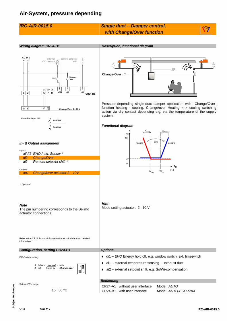
Wiring diagram CR24-B1 In- & Output assignment Inputs - ai/di1 EHO / ext. Sensor * - di2 Change/Over - ai2 Remote setpoint shift * Outputs - ao1 Change/over actuator 2…10V * Optional
Note The pin numbering corresponds to the Belimo actuator connections. Refer to the CR24 Product-Information for technical data and detailed information.
Description, functional diagram
Change-Over
Pressure depending single-duct damper application with Change/Over-function heating - cooling. Change/over Heating <–> cooling switching action via dry contact depending e.g. via the temperature of the supply system.
Functional diagram
[V]
10
0
2
Y
WclgWhtg
C-O
XP htg
t R[°C]
XP clg
coolingheating
Hint Mode setting actuator: 2...10 V
Options
di1 – EHO Energy hold off, e.g. window switch, ext. timeswitch
ai1 – external temperature sensing – exhaust duct
ai2 – external setpoint shift, e.g. So/Wi-compensation
Configuration, setting CR24-B1 DIP-Switch setting:
1 P-Band: normal - wide2 di2: Stand by - Change over
21
21
Setpoint WH range:
15...36 °C
Bedienung CR24-A1 without user interface Mode: AUTO CR24-B1 with user interface Mode: AUTO-ECO-MAX
C-O
1 2~ Change/Over 2...10 V
CR24-B1
EHO Change-Over
externalNTC - sensor
0...1
0V_remote setpointshift~
AC 24 V
1 2 7 86ao1 U5 1 U5 2 4
di2
3 5ai/di1 ai2
3y
5U5
cooling
heating
Function input di2:
Overview IRC applications
5.04 Trk
Su
bjec
t of c
hang
es
VAV-Systems, pressure independent
Application Description CR24 Type IRC-VAV-0011.0 VAV - Single-duct application,
Room temperature controlled CR24-B1
IRC-VAV-0011.1 VAV - Single-duct application, with Boost option: Temperature controlled CR24-B3
IRC-VAV-0013.0 VAV – Dual duct application, with room temperature controller CR24-B1
IRC-VAV-0015.0 VAV - Single-duct application, Room temperature controlled with 0...10V reheater valve CR24-B3
IRC-VAV-0015.1 VAV - Single-duct application, Room temperature controlled with 3-Point reheater valve CR24-B2
IRC-VAV-0016.0 VAV - Single-duct application, Room temperature controlled with 1-stage electrical reheater CR24-B2E
IRC-VAV-0016.1 VAV - Single-duct application, Room temperature controlled with 2-stage electrical reheater CR24-B2E
IRC-VAV-0018.0 VAV - Single-duct application, Room temperature controlled with ON/OFF radiator valve CR24-B2E
IRC-VAV-0111.0 VAV - Single-duct application, with chilled ceiling CR24-B3
new
new
new
new
VAV-System, pressure independent
V1.0 5.04 Trk
Su
bjec
t to
chan
ges
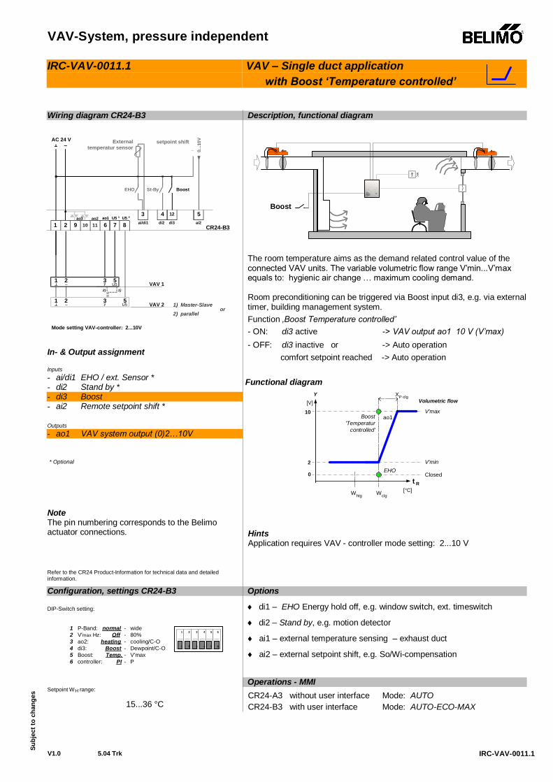
IRC-VAV-0011.0
IRC-VAV-0011.0
VAV – Single duct application Room temperature controlled
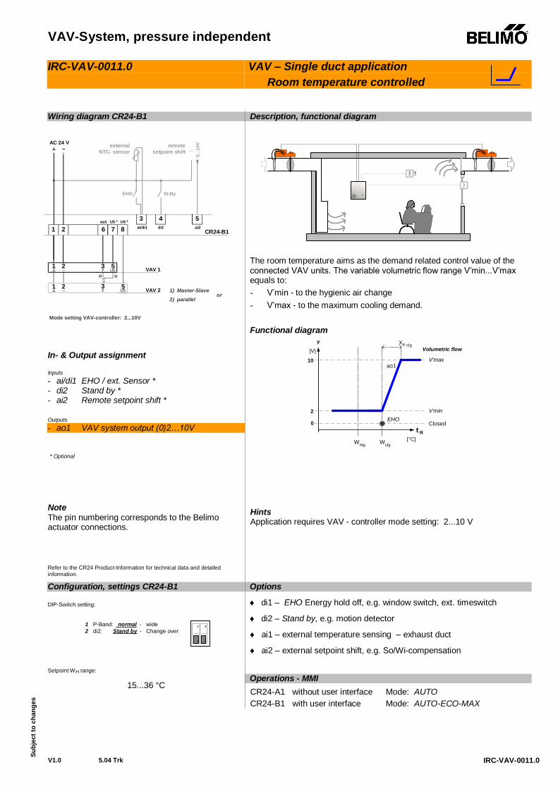
Wiring diagram CR24-B1 In- & Output assignment Inputs - ai/di1 EHO / ext. Sensor * - di2 Stand by * - ai2 Remote setpoint shift * Outputs - ao1 VAV system output (0)2…10V * Optional
Note The pin numbering corresponds to the Belimo actuator connections. Refer to the CR24 Product-Information for technical data and detailed information.
Description, functional diagram
The room temperature aims as the demand related control value of the connected VAV units. The variable volumetric flow range V’min...V’max equals to: - V’min - to the hygienic air change - V’max - to the maximum cooling demand.
Functional diagram
[V]
10
0
2
Y
WclgWhtg
ao1
V'min
XP clg
V'max
t R[°C]
EHOClosed
Volumetric flow
Hints Application requires VAV - controller mode setting: 2...10 V
Options
di1 – EHO Energy hold off, e.g. window switch, ext. timeswitch
di2 – Stand by, e.g. motion detector
ai1 – external temperature sensing – exhaust duct
ai2 – external setpoint shift, e.g. So/Wi-compensation
Configuration, settings CR24-B1 DIP-Switch setting:
1 P-Band: normal - wide2 di2: Stand by - Change over
21
21
Setpoint WH range:
15...36 °C Operations - MMI
CR24-A1 without user interface Mode: AUTO CR24-B1 with user interface Mode: AUTO-ECO-MAX
CR24-B1
EHO St-By
externalNTC- sensor
0...1
0V_remotesetpoint shift
1 3y
5U5
1 3y 5
U5
2~
2~
~AC 24 V
1 2 7 86ao1 U5 1 U5 2 4
di2
3 5ai/di1 ai2
Mode setting VAV-controller: 2...10V
VAV 2
2) 1)
1) Master-Slave2) parallel
or
VAV 1
VAV-System, pressure independent
V1.0 5.04 Trk
Su
bjec
t to
chan
ges
IRC-VAV-0011.1
IRC-VAV-0011.1
VAV – Single duct application with Boost ‘Temperature controlled’
Wiring diagram CR24-B3 In- & Output assignment Inputs - ai/di1 EHO / ext. Sensor * - di2 Stand by * - di3 Boost - ai2 Remote setpoint shift * Outputs - ao1 VAV system output (0)2…10V * Optional
Note The pin numbering corresponds to the Belimo actuator connections. Refer to the CR24 Product-Information for technical data and detailed information.
Description, functional diagram
Boost
The room temperature aims as the demand related control value of the connected VAV units. The variable volumetric flow range V’min...V’max equals to: hygienic air change … maximum cooling demand.
Room preconditioning can be triggered via Boost input di3, e.g. via external timer, building management system. Function ‚Boost Temperature controlled’ - ON: di3 active -> VAV output ao1 10 V (V’max) - OFF: di3 inactive or -> Auto operation
comfort setpoint reached -> Auto operation Functional diagram
[V]
10
0
2
Y
WclgWhtg
ao1
V'min
XP clg
V'max
t R[°C]
EHOClosed
Volumetric flow
Boost'Temperatur
controlled'
Hints Application requires VAV - controller mode setting: 2...10 V
Options
di1 – EHO Energy hold off, e.g. window switch, ext. timeswitch
di2 – Stand by, e.g. motion detector
ai1 – external temperature sensing – exhaust duct
ai2 – external setpoint shift, e.g. So/Wi-compensation
Configuration, settings CR24-B3 DIP-Switch setting:
1 P-Band: normal - wide2 V'max Hz: Off - 80%3 ao2: heating - cooling/C-O4 di3: Boost - Dewpoint/C-O5 Boost: Temp. - V'max6 controller: PI - P
21 3 54 6
21 3 54 6
Setpoint WH range:
15...36 °C
Operations - MMI CR24-A3 without user interface Mode: AUTO CR24-B3 with user interface Mode: AUTO-ECO-MAX
CR24-B3
1 3y
5U5
1 3y
5U5
1 2 7 8611109ao1 U5 1 U5 2
4 123 5di2 di3ai/di1 ai2
EHO St-By Boost
0...1
0V
_External
temperatur sensorsetpoint shift
~AC 24 V
2~
2~
ao3
VAV 2
2) 1)
1) Master-Slave2) parallel
or
VAV 1
Mode setting VAV-controller: 2...10V
ao2
VAV-System, pressure independent
V1.1 6.05 Trk
Su
bjec
t to
chan
ges
A4-VAV-0013-0C3-0en
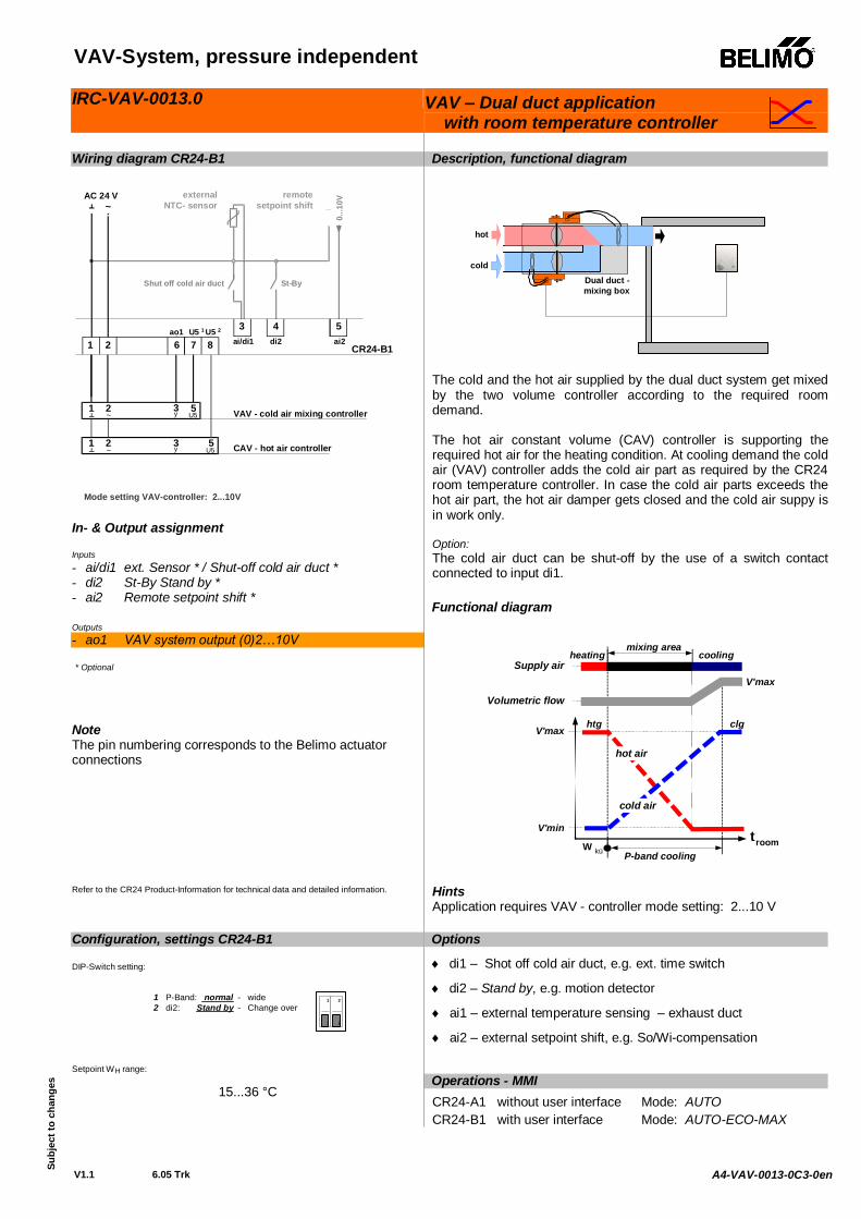
IRC-VAV-0013.0 VAV – Dual duct application with room temperature controller
Wiring diagram CR24-B1 In- & Output assignment Inputs - ai/di1 ext. Sensor * / Shut-off cold air duct * - di2 St-By Stand by * - ai2 Remote setpoint shift * Outputs - ao1 VAV system output (0)2…10V * Optional
Note The pin numbering corresponds to the Belimo actuator connections Refer to the CR24 Product-Information for technical data and detailed information.
Description, functional diagram
hot
coldDual duct -mixing box
The cold and the hot air supplied by the dual duct system get mixed by the two volume controller according to the required room demand. The hot air constant volume (CAV) controller is supporting the required hot air for the heating condition. At cooling demand the cold air (VAV) controller adds the cold air part as required by the CR24 room temperature controller. In case the cold air parts exceeds the hot air part, the hot air damper gets closed and the cold air suppy is in work only. Option: The cold air duct can be shut-off by the use of a switch contact connected to input di1.
Functional diagram
troomW kü
V'max
V'min
P-band cooling
mixing area
Supply air
Volumetric flow
heating cooling
hot air
cold air
V'max
htg clg
Hints Application requires VAV - controller mode setting: 2...10 V
Options
di1 – Shot off cold air duct, e.g. ext. time switch
di2 – Stand by, e.g. motion detector
ai1 – external temperature sensing – exhaust duct
ai2 – external setpoint shift, e.g. So/Wi-compensation
Configuration, settings CR24-B1 DIP-Switch setting:
1 P-Band: normal - wide2 di2: Stand by - Change over
21
21
Setpoint WH range:
15...36 °C Operations - MMI
CR24-A1 without user interface Mode: AUTO CR24-B1 with user interface Mode: AUTO-ECO-MAX
CR24-B1
Shut off cold air duct St-By
0...1
0V_
1 3y 5
U5
1 3y
5U5
2~
2~
~AC 24 V
1 2 7 86ao1 U5 1 U5 2 4
di2
3 5ai/di1 ai2
Mode setting VAV-controller: 2...10V
CAV - hot air controller
VAV - cold air mixing controller
externalNTC- sensor
remotesetpoint shift
VAV-System, pressure independent
V1.0 5.04 Trk
Su
bjec
t to
chan
ges
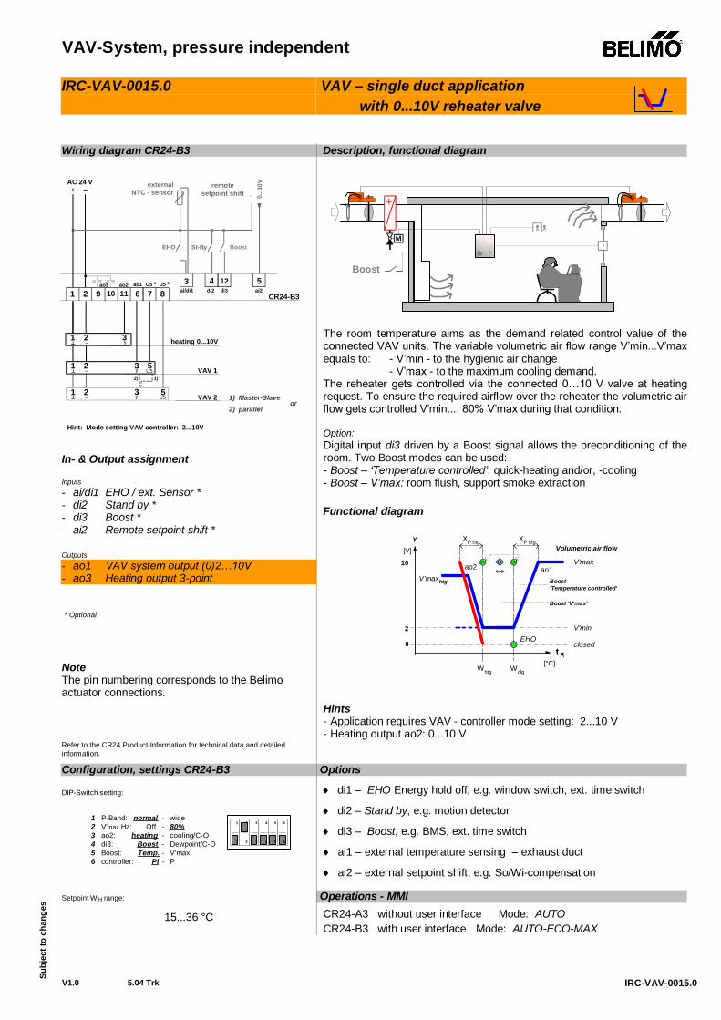
IRC-VAV-0015.0
IRC-VAV-0015.0
VAV – single duct application with 0...10V reheater valve
Wiring diagram CR24-B3 In- & Output assignment Inputs - ai/di1 EHO / ext. Sensor * - di2 Stand by * - di3 Boost * - ai2 Remote setpoint shift * Outputs - ao1 VAV system output (0)2…10V - ao3 Heating output 3-point * Optional
Note The pin numbering corresponds to the Belimo actuator connections. Refer to the CR24 Product-Information for technical data and detailed information.
Description, functional diagram
+
M
Boost
The room temperature aims as the demand related control value of the connected VAV units. The variable volumetric air flow range V’min...V’max equals to: - V’min - to the hygienic air change - V’max - to the maximum cooling demand. The reheater gets controlled via the connected 0…10 V valve at heating request. To ensure the required airflow over the reheater the volumetric air flow gets controlled V’min.... 80% V’max during that condition. Option: Digital input di3 driven by a Boost signal allows the preconditioning of the room. Two Boost modes can be used: - Boost – ‘Temperature controlled’: quick-heating and/or, -cooling - Boost – V’max: room flush, support smoke extraction
Functional diagram
[V]
10
0
2
Y
WclgWhtg
ao1
V'min
XP clg
V'max
t R[°C]
EHOclosed
Volumetric air flowXP htg
ao2V'maxhtg
Boost 'V'max'
x x
Boost'Temperature controlled'
Hints - Application requires VAV - controller mode setting: 2...10 V - Heating output ao2: 0...10 V
Options
di1 – EHO Energy hold off, e.g. window switch, ext. time switch
di2 – Stand by, e.g. motion detector
di3 – Boost, e.g. BMS, ext. time switch
ai1 – external temperature sensing – exhaust duct
ai2 – external setpoint shift, e.g. So/Wi-compensation
Configuration, settings CR24-B3 DIP-Switch setting:
1 P-Band: normal - wide2 V'max Hz: Off - 80%3 ao2: heating - cooling/C-O4 di3: Boost - Dewpoint/C-O5 Boost: Temp. - V'max6 controller: PI - P
21 3 54 6
21 3 54 6
Setpoint WH range:
15...36 °C
Operations - MMI CR24-A3 without user interface Mode: AUTO CR24-B3 with user interface Mode: AUTO-ECO-MAX
CR24-B3
1 3y 5U5
1 3y 5
U5
1 2 7 8611109
heating 0...10V
ao1 U5 1 U5 2 4 123 5di2 di3ai/di1 ai2
EHO St-By Boost
0...1
0V
_external
NTC - sensorremote
setpoint shift~AC 24 V
2~
2~
1 3
ao3
VAV 2
2) 1)
1) Master-Slave2) parallel
or
VAV 1
Hint: Mode setting VAV controller: 2...10V
ao2
2~ y
VAV-System, pressure independent
V1.0 5.04 Trk
Su
bjec
t to
chan
ges
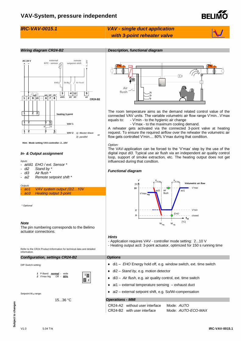
IRC-VAV-0015.1
IRC-VAV-0015.1
VAV - single duct application with 3-point reheater valve
Wiring diagram CR24-B2 In- & Output assignment Inputs - ai/di1 EHO / ext. Sensor * - di2 Stand by * - di3 Air flush * - ai2 Remote setpoint shift * Outputs - ao1 VAV system output (0)2…10V - ao3 Heating output 3-point * Optional
Note The pin numbering corresponds to the Belimo actuator connections. Refer to the CR24 Product-Information for technical data and detailed information.
Description, functional diagram
+
M
Airflush
The room temperature aims as the demand related control value of the connected VAV units. The variable volumetric air flow range V’min...V’max equals to: - V’min - to the hygienic air change - V’max - to the maximum cooling demand. A reheater gets activated via the connected 3-point valve at heating request. To ensure the required airflow over the reheater the volumetric air flow gets controlled V’min.... 80% V’max during that condition. Option: The VAV-application can be forced to the ‘V’max’ step by the use of the digital input di3. Typical use air flush via an independent air quality control loop, support of smoke extraction, etc. The heating output does not get influenced during that condtion.
Functional diagram
[V]
10
0
2
Y
WclgWhtg
ao1
V'min
XP clg
V'max
t R[°C]
EHOclosed
Volumetric air flowXP htg
ao3V'max htg
airflush
Hints - Application requires VAV - controller mode setting: 2...10 V - Heating output ao3: 3-point actuator, optimized for 150 s running time
Options
di1 – EHO Energy hold off, e.g. window switch, ext. time switch
di2 – Stand by, e.g. motion detector
di3 – Air flush, e.g. air quality control, ext. time switch
ai1 – external temperature sensing – exhaust duct
ai2 – external setpoint shift, e.g. So/Wi-compensation
Configuration, settings CR24-B2 DIP-Switch setting:
1 P-Band: normal - wide2 V'max htg Off - 80%
212
1 2
Setpoint WH range:
15...36 °C Operations - MMI CR24-A2 without user interface Mode: AUTO CR24-B2 with user interface Mode: AUTO-ECO-MAX
CR24-B2
1 3y 5U5
1 3y 5
U5
1 2 7 8611109
heating 3-point
ao1 U5 1 U5 24 123 5
di2 di3ai/di1 ai2
EHO St-By Air flush
0...1
0V
_
externalNTC - sensor
remotesetpoint shift~
AC 24 V
2~
2~
1 2 3
ao3
VAV 2
2) 1)
1) Master-Slave2) parallel
or
VAV 1
Hint: Mode setting VAV-controller: 2...10V
VAV-System, pressure independent
V1.1 6.05 Trk
Su
bjec
t to
chan
ges!
A4-VAV-0016-0C3-0de
IRC-VAV-0016.0 VAV – single duct application with 1-stage electrical reheater
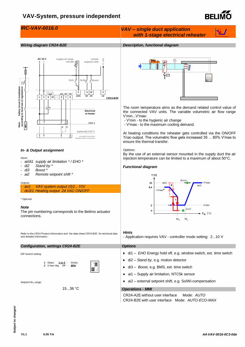
Wiring diagram CR24-B2E In- & Output assignment Inputs - ai/di1 supply air limitation * / EHO * - di2 Stand by * - di3 Boost * - ai2 Remote setpoint shift * Outputs - ao1 VAV system output (0)2…10V - do3/1 Heating output 24 VAC ON/OFF * Optional Note The pin numbering corresponds to the Belimo actuator connections. Refer to the CR24 Product Information and the data sheet CR24-B2E for technical data and detailed information..
Description, functional diagram
°C
The room temperature aims as the demand related control value of the connected VAV units. The variable volumetric air flow range V’min...V’max: - V’min - to the hygienic air change - V’max - to the maximum cooling demand. At heating conditions the reheater gets controlled via the ON/OFF Triac-output. The volumetric flow gets increased 35 ... 80% V’max to ensure the thermal transfer. Options: By the use of an external sensor mounted in the supply duct the air injection temperature can be limited to a maximum of about 50°C.
Functional diagram
10
0
2
Y [V]
WCWH
ao1
V'min
V'max
t R [°C]
Boost
V'maxH
II
I
8,4
do3
EHO
Hints - Application requires VAV - controller mode setting: 2...10 V
Options
di1 – EHO Energy hold off, e.g. window switch, ext. time switch
di2 – Stand by, e.g. motion detector
di3 – Boost, e.g. BMS, ext. time switch
ai1 – Supply air limitation, NTC5k sensor
ai2 – external setpoint shift, e.g. So/Wi-compensation
Configuration, settings CR24-B2E DIP-Switch setting:
1 Steps: 1 or 2 - binary2 V'max Htg: Off - 80%
21
21
Setpoint WH range:
15...36 °C Operations - MMI CR24-A2E without user interface Mode: AUTO CR24-B2E with user interface Mode: AUTO-ECO-MAX
1 3y
5U5
2~
(optional) VAV 2
a) parallel connectionb) Master-Slave connection
a) b)
CR24-B2E
1 3y
5U5
1 2 7 8611109
Electricalre-heater
ao1 U5 1 U5 24 123 5
di2 di3ai/di1 ai2
0...1
0V
_~AC 24 V
2~ VAV 1
ao3
°C
Not
e:
Safe
ty c
ircui
t & in
stal
latio
nac
cord
ing
to lo
cal l
aw &
regu
latio
ns!
EHO St-By Boost
remotesetpoint shift
supply air temp.NTC5K
VAV-System, pressure independent
V1.1 6.05 Trk
Su
bjec
t to
chan
ges
A4-VAV-0016-0C3-0de
IRC-VAV-0016.1 VAV – single duct application with 2-stage electrical reheater
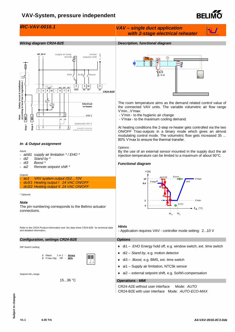
Wiring diagram CR24-B2E In- & Output assignment Inputs - ai/di1 supply air limitation * / EHO * - di2 Stand by * - di3 Boost * - ai2 Remote setpoint shift * Outputs - ao1 VAV system output (0)2…10V - do3/1 Heating output I 24 VAC ON/OFF - do3/2 Heating output II 24 VAC ON/OFF
* Optional Note The pin numbering corresponds to the Belimo actuator connections. Refer to the CR24 Product-Information and the data sheet CR24-B2E for technical data and detailed information..
Description, functional diagram
°C
I-II-III
The room temperature aims as the demand related control value of the connected VAV units. The variable volumetric air flow range V’min...V’max: - V’min - to the hygienic air change - V’max - to the maximum cooling demand. At heating conditions the 2-step re-heater gets controlled via the two ON/OFF Triac-outputs in a binary mode which gives an almost modulating control mode. The volumetric flow gets increased 35 ... 80% V’max to ensure the thermal transfer. Options: By the use of an external sensor mounted in the supply duct the air injection temperature can be limited to a maximum of about 50°C.
Functional diagram
10
0
2
Y [V]
WCWH
ao1
V'min
V'max
t R [°C]
Boost
V'maxH
I
8,4
do3 I/II
EHO
II
III
Hints - Application requires VAV - controller mode setting: 2...10 V
Options
di1 – EHO Energy hold off, e.g. window switch, ext. time switch
di2 – Stand by, e.g. motion detector
di3 – Boost, e.g. BMS, ext. time switch
ai1 – Supply air limitation, NTC5k sensor
ai2 – external setpoint shift, e.g. So/Wi-compensation
Configuration, settings CR24-B2E DIP-Switch setting:
1 Steps: 1 or 2 - binary2 V'max Htg: Off - 80%
21
21
Setpoint WH range:
15...36 °C Operations - MMI CR24-A2E without user interface Mode: AUTO CR24-B2E with user interface Mode: AUTO-ECO-MAX
1 3y
5U5
2~
(optional) VAV 2
a) parallel connectionb) Master-Slave connection
a) b)
CR24-B2E
1 3y
5U5
1 2 7 8611109
Electricalre-heater
ao1 U5 1 U5 24 123 5
di2 di3ai/di1 ai2
0...1
0V
_~AC 24 V
2~ VAV 1
ao3
°C
Not
e:
Safe
ty c
ircui
t & in
stal
latio
nac
cord
ing
to lo
cal l
aw &
regu
latio
ns !
EHO St-By Boost
remotesetpoint shift
supply air temp.NTC5K
Step
I
Step
II
I
II
VAV-System, pressure independent
V1.1 6.05 Trk
Su
bjec
t to
chan
ges
A4-VAV-0018-0C3-0de
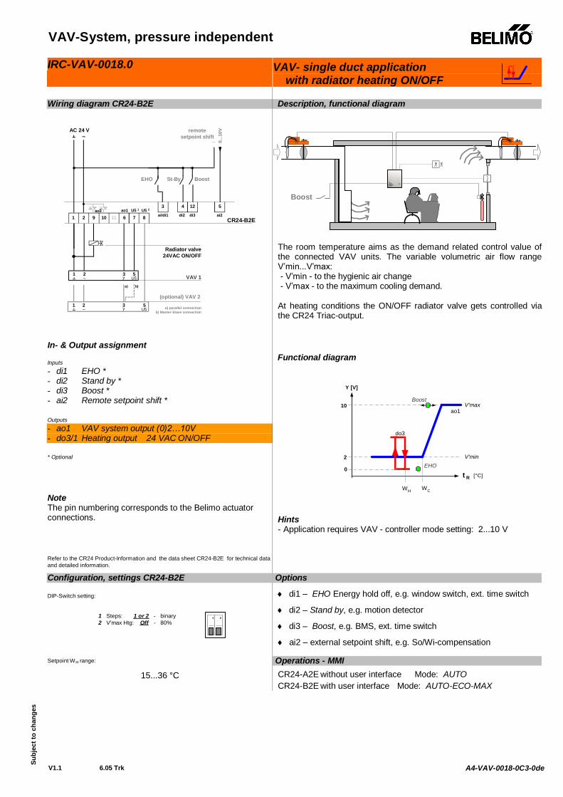
IRC-VAV-0018.0 VAV- single duct application with radiator heating ON/OFF
Wiring diagram CR24-B2E In- & Output assignment Inputs - di1 EHO * - di2 Stand by * - di3 Boost * - ai2 Remote setpoint shift * Outputs - ao1 VAV system output (0)2…10V - do3/1 Heating output 24 VAC ON/OFF * Optional
Note The pin numbering corresponds to the Belimo actuator connections. Refer to the CR24 Product-Information and the data sheet CR24-B2E for technical data and detailed information.
Description, functional diagram
Boost
The room temperature aims as the demand related control value of the connected VAV units. The variable volumetric air flow range V’min...V’max: - V’min - to the hygienic air change - V’max - to the maximum cooling demand. At heating conditions the ON/OFF radiator valve gets controlled via the CR24 Triac-output.
Functional diagram
10
0
2
Y [V]
WCWH
ao1
V'min
V'max
t R [°C]
Boost
do3
EHO
Hints - Application requires VAV - controller mode setting: 2...10 V
Options
di1 – EHO Energy hold off, e.g. window switch, ext. time switch
di2 – Stand by, e.g. motion detector
di3 – Boost, e.g. BMS, ext. time switch
ai2 – external setpoint shift, e.g. So/Wi-compensation
Configuration, settings CR24-B2E DIP-Switch setting:
1 Steps: 1 or 2 - binary2 V'max Htg: Off - 80%
21
21
Setpoint WH range:
15...36 °C
Operations - MMI CR24-A2E without user interface Mode: AUTO CR24-B2E with user interface Mode: AUTO-ECO-MAX
1 3y
5U5
2~
(optional) VAV 2
a) parallel connectionb) Master-Slave connection
a) b)
CR24-B2E
1 3y
5U5
1 2 7 8611109
Radiator valve24VAC ON/OFF
ao1 U5 1 U5 24 123 5
di2 di3ai/di1 ai20.
..10V
_~AC 24 V
2~ VAV 1
ao3
EHO St-By Boost
remotesetpoint shift
VAV-System, pressure independent
V1.0 5.04 Trk
Su
bjec
t to
chan
ges
IRC-VAV-0111.0
IRC-VAV-0111.1
VAV - single duct application with Chilled ceiling
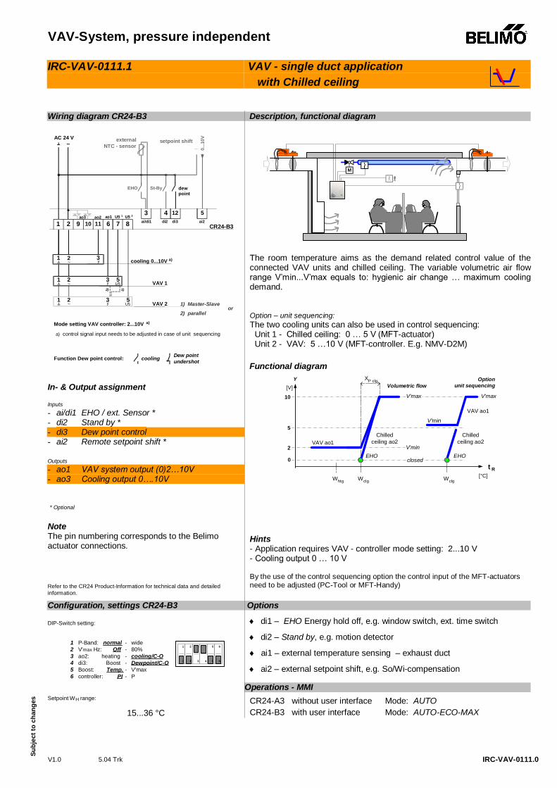
Wiring diagram CR24-B3 In- & Output assignment Inputs - ai/di1 EHO / ext. Sensor * - di2 Stand by * - di3 Dew point control - ai2 Remote setpoint shift * Outputs - ao1 VAV system output (0)2…10V - ao3 Cooling output 0….10V * Optional
Note The pin numbering corresponds to the Belimo actuator connections. Refer to the CR24 Product-Information for technical data and detailed information.
Description, functional diagram
M
The room temperature aims as the demand related control value of the connected VAV units and chilled ceiling. The variable volumetric air flow range V’min...V’max equals to: hygienic air change … maximum cooling demand.
Option – unit sequencing: The two cooling units can also be used in control sequencing: Unit 1 - Chilled ceiling: 0 … 5 V (MFT-actuator) Unit 2 - VAV: 5 …10 V (MFT-controller. E.g. NMV-D2M)
Functional diagram
[V]
10
0
2
Y
WclgWhtg
XP clg
t R[°C]
EHO
Volumetric flow
V'min
VAV ao1
Optionunit sequencing
VAV ao1
V'max
closed
Wclg
V'minEHO
5Chilled
ceiling ao2Chilled
ceiling ao2
V'max
Hints - Application requires VAV - controller mode setting: 2...10 V - Cooling output 0 … 10 V By the use of the control sequencing option the control input of the MFT-actuators need to be adjusted (PC-Tool or MFT-Handy)
Options
di1 – EHO Energy hold off, e.g. window switch, ext. time switch
di2 – Stand by, e.g. motion detector
ai1 – external temperature sensing – exhaust duct
ai2 – external setpoint shift, e.g. So/Wi-compensation
Configuration, settings CR24-B3 DIP-Switch setting:
1 P-Band: normal - wide2 V'max Hz: Off - 80%3 ao2: heating - cooling/C-O4 di3: Boost - Dewpoint/C-O5 Boost: Temp. - V'max6 controller: PI - P
21 3 54 6
21 3 54 6
Setpoint WH range:
15...36 °C
Operations - MMI CR24-A3 without user interface Mode: AUTO CR24-B3 with user interface Mode: AUTO-ECO-MAX
cooling Dew pointundershotFunction Dew point control:
CR24-B3
1 3y
5U5
1 3y
5U5
1 2 7 8611109
cooling 0...10V a)
ao1 U5 1 U5 24 123 5
di2 di3ai/di1 ai2
EHO St-By dewpoint
0...1
0V
_external
NTC - sensorsetpoint shift~
AC 24 V
2~
2~
1 3
ao3
VAV 2
2) 1)
1) Master-Slave
2) parallelor
VAV 1
Mode setting VAV controller: 2...10V a)
ao2
2~ y
a) control signal input needs to be adjusted in case of unit sequencing
Overview IRC applications
5.04 Trk
Su
bjec
t of c
hang
es
Water applications
Application Description CR24 Type IRC-WAT-0011.0 2-pipe system with 3-point reheater valve,
Room temperature controlled CR24-B2
IRC-WAT-0015.0 2-pipe system Heat exchanger, with Change/Over function CR24-B1
Water application
V1.0 5.04 Trk
Su
bjec
t to
chan
ges
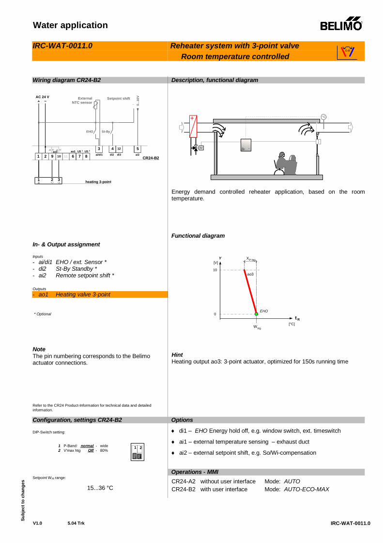
IRC-WAT-0011.0
IRC-WAT-0011.0
Reheater system with 3-point valve Room temperature controlled
Wiring diagram CR24-B2 In- & Output assignment Inputs - ai/di1 EHO / ext. Sensor * - di2 St-By Standby * - ai2 Remote setpoint shift * Outputs - ao1 Heating valve 3-point * Optional
Note The pin numbering corresponds to the Belimo actuator connections. Refer to the CR24 Product-Information for technical data and detailed information.
Description, functional diagram
+ °C
M
Energy demand controlled reheater application, based on the room temperature.
Functional diagram
Y
Whtg
t R[°C]
EHO
XP htg
ao3
[V]
10
0
Hint Heating output ao3: 3-point actuator, optimized for 150s running time
Options
di1 – EHO Energy hold off, e.g. window switch, ext. timeswitch
ai1 – external temperature sensing – exhaust duct
ai2 – external setpoint shift, e.g. So/Wi-compensation
Configuration, settings CR24-B2 DIP-Switch setting:
1 P-Band: normal - wide2 V'max htg Off - 80%
21
21 2
Setpoint WH range:
15...36 °C
Operations - MMI CR24-A2 without user interface Mode: AUTO CR24-B2 with user interface Mode: AUTO-ECO-MAX
C-O
CR24-B21 2 7 8611109
heating 3-point
ao1 U5 1 U5 24 123 5
di2 di3ai/di1 ai2
EHO St-By
0...1
0V
_External
NTC sensorSetpoint shift
~AC 24 V
1 2 3
ao3
Water application
V1.0 5.04 Trk
Su
bjec
t to
chan
ges
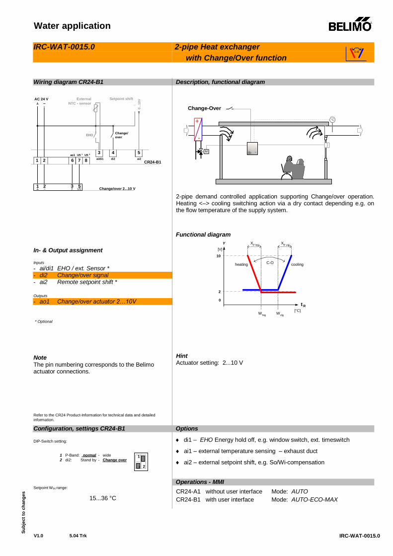
IRC-WAT-0015.0
IRC-WAT-0015.0
2-pipe Heat exchanger with Change/Over function
Wiring diagram CR24-B1 In- & Output assignment Inputs - ai/di1 EHO / ext. Sensor * - di2 Change/over signal - ai2 Remote setpoint shift * Outputs - ao1 Change/over actuator 2…10V * Optional
Note The pin numbering corresponds to the Belimo actuator connections. Refer to the CR24 Product-Information for technical data and detailed information.
Description, functional diagram
+ °C
M
-
Change-Over
2-pipe demand controlled application supporting Change/over operation. Heating <–> cooling switching action via a dry contact depending e.g. on the flow temperature of the supply system.
Functional diagram
[V]
10
0
2
Y
WclgWhtg
C-O
XP htg
t R[°C]
XP clg
coolingheating
Hint Actuator setting: 2...10 V
Options
di1 – EHO Energy hold off, e.g. window switch, ext. timeswitch
ai1 – external temperature sensing – exhaust duct
ai2 – external setpoint shift, e.g. So/Wi-compensation
Configuration, settings CR24-B1 DIP-Switch setting:
1 P-Band: normal - wide2 di2: Stand by - Change over
21
21
Setpoint WH range:
15...36 °C
Operations - MMI CR24-A1 without user interface Mode: AUTO CR24-B1 with user interface Mode: AUTO-ECO-MAX
C-O
1 2~ Change/over 2...10 V
CR24-B1
EHO Change/over
ExternalNTC - sensor
0...1
0V_Setpoint shift
~AC 24 V
1 2 7 86ao1 U5 1 U5 2 4
di2
3 5ai/di1 ai2
3y 5
U5

Overview IRC applications
5.04 Trk
Su
bjec
t of c
hang
es
Heat-/Chilled Ceiling-Systems
Application Description CR24 Type IRC-CLC-0011.0 Chilled ceiling - 2-pipe-system,
Room temperature controlled CR24-B3
IRC-CLC-0015.0 Heat-/Chilled ceiling - 2-pipe-system, with Change-over function CR24-B3
Heat-/Chilled ceiling system
V1.0 6.04 Trk
Su
bjec
t to
chan
ges
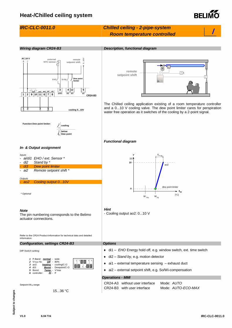
IRC-CLC-0011.0
IRC-CLC-0011.0
Chilled ceiling - 2-pipe-system Room temperature controlled
Wiring diagram CR24-B3 In- & Output assignment Inputs - ai/di1 EHO / ext. Sensor * - di2 Stand by * - di3 Dew point limiter - ai2 Remote setpoint shift * Outputs - ao2 Cooling out put 0. .. 10V * Optional
Note The pin numbering corresponds to the Belimo actuator connections. Refer to the CR24 Product-Information for technical data and detailed information.
Description, functional diagram
Mremote
setpoint shift
The Chilled ceiling application existing of a room temperature controller and a 0...10 V cooling valve. The dew point limiter cares for perspiration water free operation as it switches of the cooling by a 2-point signal.
Functional diagram
[V]
10
0
Y
WclgW htg
ao2
XP clg
t R[°C]
dew point limiter
Hint - Cooling output ao2: 0...10 V
Options
di1 – EHO Energy hold off, e.g. window switch, ext. time switch
di2 – Stand by, e.g. motion detector
ai1 – external temperature sensing – exhaust duct
ai2 – external setpoint shift, e.g. So/Wi-compensation
Configuration, settings CR24-B3 DIP-Switch setting:
1 P-Band: normal - wide2 V'max Hz: Off - 80%3 ao2: heating - cooling/C-O4 di3: Boost - Dewpoint/C-O5 Boost: Temp. - V'max6 controller: PI - P
21 3 54 6
21 3 54 6
Setpoint WH range:
15...36 °C
Operations - MMI CR24-A3 without user interface Mode: AUTO CR24-B3 with user interface Mode: AUTO-ECO-MAX
CR24-B3
5U5
1 2 7 8611109
cooling 0...10V
ao1 U5 1 U5 24 123 5
di2 di3ai/di1 ai2
EHO St-By Dew pointlimiter
0...1
0V
_external
NTC sensorremote
setpoint shift~AC 24 V
1 3
ao3 ao2
2~ y
cooling
belowDew point
Function Dew point limiter:
Heat-/Chilled ceiling system
V1.0 6.04 Trk
Su
bjec
t to
chan
ges
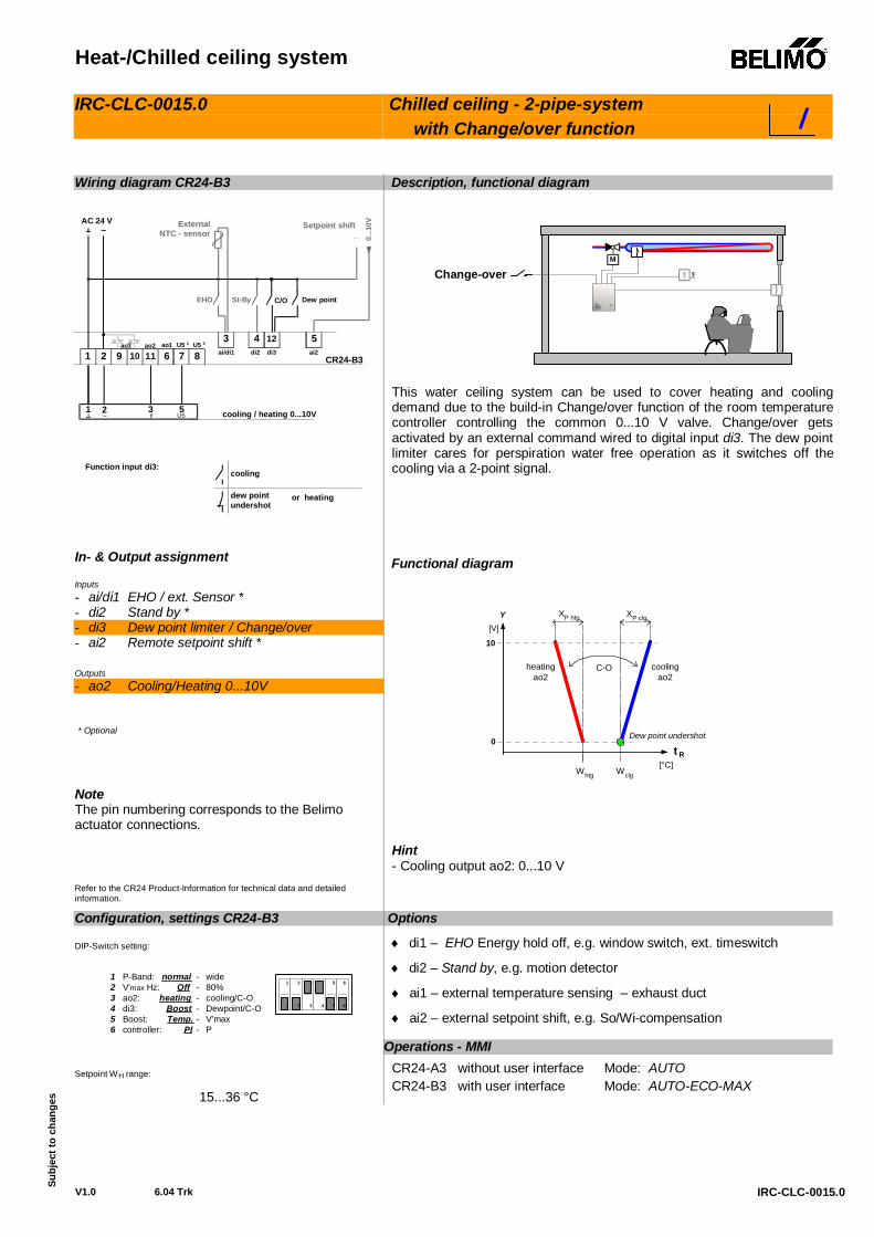
IRC-CLC-0015.0
IRC-CLC-0015.0
Chilled ceiling - 2-pipe-system with Change/over function
Wiring diagram CR24-B3 In- & Output assignment Inputs - ai/di1 EHO / ext. Sensor * - di2 Stand by * - di3 Dew point limiter / Change/over - ai2 Remote setpoint shift * Outputs - ao2 Cooling/ Heat ing 0. .. 10V * Optional
Not e The pi n numberi ng corresponds to the Bel imo actuator connections. Refer to the CR24 Product-In f o rm a ti o n f o r t ec h n ic a l d a t a a n d d e ta i le d inform ation.
Description, functional diagr am
M
Ch an ge-over
Thi s water ceil i ng system can be used to cover heati ng and cooli ng dem and due to the build-in Change/over function of the room tem perature controller controlling the common 0...10 V valve. Change/over gets activated by an ext ernal command wired to digital input di3. The dew point limiter cares for perspiration water free operation as it switches off the cooling via a 2-point signal.
Functional diagram
[V ]
10
0
Y
WclgWhtg
XP clg
t R[°C]
Dew point undershot
XP htg
C-O coolingao2
heatingao2
Hint - Cooling output ao2: 0...10 V
Options
di1 – EHO Energy hold off, e.g. window switch, ext. timeswitch
di2 – Stand by, e.g. motion detector
ai1 – external temperature sensing – exhaust duct
ai2 – external setpoint shift, e.g. So/Wi-compensation
Configuration, settings CR24-B3 DIP-Switch setting:
1 P-Band: normal - wide2 V'max Hz: Off - 80%3 ao2: heating - cooling/C-O4 di3: Boost - Dewpoint/C-O5 Boost: Temp. - V'max6 controller: PI - P
21 3 54 6
21 3 54 6
Setpoint WH range:
15...36 °C
Operations - MMI CR24-A3 without user interface Mode: AUTO CR24-B3 with user interface Mode: AUTO-ECO-MAX
CR24-B3
5U5
1 2 7 8611109
cooling / heating 0...10V
ao1 U5 1 U5 24 123 5
di2 di3ai/di1 ai2
EHO St-By Dew point
0...1
0V
_External
NTC - sensorSetpoint shift~
AC 24 V
1 3
ao3 ao2
2~ y
cooling
dew pointundershot
Function input di3:
C/O
or heating

1
Notes