HPCL CHAMPARAN – LPG PLANT
RISK ANALYSIS
M/s. HINDUSTAN PETROLEUM CORPORATION LTD
(Construction of New LPG Plant for Bottling
Facilities at Harsidhi, East Champaran
SY.NO.1, 1/2066, 5, 6, 201, 206, 207
PANAPUR & KUBEYA VILLAGE, HARSIDHI BLOCK
EAST CHAMPARN DISTRICT, BIHAR STATE
PREPARED BY
SV ENVIRO LABS & CONSULTANTS
Recognized by GOI, MOEF, QCI Accredited
Enviro House, B
Visakhapatnam
Andhra Pradesh
LPG PLANT RISK ANALYSIS
RISK ANALYSIS
M/s. HINDUSTAN PETROLEUM CORPORATION LTD
Construction of New LPG Plant for Bottling & Storage
Facilities at Harsidhi, East Champaran)
1/2066, 5, 6, 201, 206, 207
PANAPUR & KUBEYA VILLAGE, HARSIDHI BLOCK
EAST CHAMPARN DISTRICT, BIHAR STATE
PREPARED BY
SV ENVIRO LABS & CONSULTANTS
Recognized by GOI, MOEF, QCI Accredited
Enviro House, B-1, Block –B, IDA,
Autonagar,
Visakhapatnam-530012
Andhra Pradesh
RISK ANALYSIS
Page 1
Dec’2017
& Storage
HPCL CHAMPARAN LPG PLANT RISK ANALYSIS
Page 2
CONTENTS
S.No. Description Page. No.
1.0 Introduction 07-07
1.1 Study Objectives 07-08
1.2 Scope of study 08-09
1.3 Objectives, Philosophy And Methodology 09-09
1.4 Risk Analysis And Risk Assessment 12-12
1.5 Quantitative Risk Assessment 13-13
1.6 Use Of QRA Results 13-13
1.7 Software Used 14-14
1.8 Weather Category 14-14
1.9 Methodology Adopted For Consequence Analysis 15-15
1.10 Hazards of Materials 15-17
1.11 Fire and Explosion Index (F & EI) 17-17
1.12 DOW F & EI Hazard Classification 17-18
1.13 FEI & TI Methodology 18-20
1.14 LPG-Liquefied Petroleum Gas 20-22
1.15 Liquefied Petroleum Gas (LPG) 23-24
1.16 Hazards Associated With Toxic Materials 24-25
1.17 Damage Criteria 25-25
1.17.1 Thermal Damage 26-26
1.18 Selected Failure Cases 27-27
1.19 Effect of Release 28-29
1.20 Consequence Analysis 29-29
1.20.1 Introduction 29-29
1.20.2 Event Outcomes 30-30
1.20.3 Event Tree Analysis to Define Outcome of Release 32-32
1.20.4 Fault Tree Analysis to Explore Propensity for Occurrence of the Top
Event
32-33
1.21 Fire Protection and Fire Fighting System 54-54
HPCL CHAMPARAN LPG PLANT RISK ANALYSIS
Page 3
1.21.1 Fire Fighting Facilities 54-54
1.21.2 Safety & Security Features in the Proposed Plant 54-54
1.22 Mitigation Measures 55-56
1.23 Conclusion 56-56
2.0 Visualization Of MCA Scenarios 57-57
2.1 Introduction 57-57
2.1.1 Chemical Inventory Analysis 57-57
2.1.2 Identification of Chemical Release & Accident Scenarios 57-57
2.2 Pertinent Past Accident Data/Case History Analysis 57-57
2.2.1 Industrial Disasters 57-58
2.2.2 Types & Consequences of Previous Fire & Explosion 58-58
2.2.3 Lessons from Previous Accidents in Chemical Industries 59-59
2.3 Short listing of MCA scenarios 59-59
2.4 Mathematical And Analytical Models For Hazard Analysis 59-61
2.5 Models For Determining The Source Strength for Release of a
Hazardous Substance
61-61
2.5.1 Instantaneous Release 61-62
2.5.2 Semi-continuous Outflow 62-63
2.6 Models for Dispersion 63-63
2.7 Heavy Gas Dispersion Model 63-63
2.8 Climatological Conditions 63-64
2.9 Results of Maximum Credible Accident (MCA) Analysis 64-64
2.9.1 Backfire Potential due to Continuous Release of LPG from MSV
Continuous release
64-64
2.9.2 Unconfined Vapour Cloud Explosion (UVCE) 64-65
2.9.2.1 Instantaneous Release 65-65
2.9.2.2 Mounded Storage 65-66
2.9.2.3 Consequences of the Identified Accident Scenarios 66-66
2.10 Domino Effects 66-66
3.0 QRA Recommendations 67-67
HPCL CHAMPARAN LPG PLANT RISK ANALYSIS
Page 4
LIST OF TABLES
Table No. Description Page No.
1.1 Damage Due to Incident Radiation Intensity 26-26
1.2 Damage Effects of Blast Overpressure
26-26
1.3 Flash Fire Envelope 40-40
1.4 Distance to Concentration Results 42-42
1.5 Explosion Effects 44-44
1.6 Radiation Effects 45-45
1.7 Weather Category 1.5/D & 5/D 46-49
1.8 Distance to Concentration Results 51-51
1.9 All flammable results are reported at the cloud centerline height 52-52
1.0 Radius Effects 53-53
2.1 Short Listed MCA Scenarios for the LPG Plant 59-59
LIST OF FIGURES
Figure No. Description Page No.
1.1 Methodology 10-10
1.2 Site Plan 11-11
1.3 IPRA (Individual Risk per Annum) 12-12
1.4 Event Tree for continuous release without rain-out (from PHAST) 30-30
1.5 Event Tree for Instantaneous release without rain-out (from PHAST) 30-30
1.6 Event Tree for continuous release with rain-out (from PHAST) 31-31
1.7 Event Tree for Instantaneous release with rain-out (from PHAST) 31-31
1.8 Event Tree Analysis for Rupture & Leak scenarios 34-34
1.9 Event Analysis 34-34
1.10 Release of flammable liquid 35-35
1.11 Vessel/pipe work rupture by external fire 35-35
HPCL CHAMPARAN LPG PLANT RISK ANALYSIS
Page 5
1.12 Fire at Pump House 36-36
1.13 Fire at DG Set Room 36-36
1.14 Fire at MSV area 37-37
1.15 Overheating of an electric motor 37-37
1.16 Fire in MSV Area 38-38
1.17 Common mode failure classes 39-39
1.18 Flash Fire Envelope-Leak 40-40
1.19 Centerline Concentration Vs Distance – Leak 41-41
1.20 Late Explosion at Distance – Leak 43-43
1.21 Late Explosion Worst Case Radii – Leak 44-44
1.22 Intensity Radii for Jet Fire – Leak 45-45
1.23 Radiation Vs Distance for Jet Fire - Leak 46-46
1.24 Concentration Vs Distance – Catastrophic rupture 49-49
1.25 Centerline Concentration Vs Distance – Short Pipe 50-50
1.26 Flash Fire Envelope – Short Pipe 52-52
1.27 Intensity Radii for Jet Fire – Short Pipe 53-53
HPCL CHAMPARAN LPG PLANT RISK ANALYSIS
Page 6
List of Abbreviations used in the Quantitative Risk Analysis:-
1. ROV Remote Operated Valve
2. OISD Oil Industrial Safety Directorate
3. TLF Tank Lorry Filling Gantry
4. QRA Quantitative Risk Analysis
5. LCS Local Control Station
6. ALARP As low as reasonably practicable
7. MCLS Maximum Credible Loss Scenario
8. ELR Environmental Lapse Rate
9. DALR Dry Adiabatic Lapse Rate
10. UDM Unified Dispersion Model
11. LFL Lower Flammability Limit
12. UFL Upper Flammability Limit
13. VCE Vapour Cloud Explosion
14. F&EI Fire and Explosion Index
15. MSDS Material Safety Data Sheets
16. MSIHC Manufacture, Storage and Import of Hazardous
Chemicals
17. AIHA American Industrial Hygiene Association
18. ERPG Emergency Response Planning Guidelines
19. IDLH Immediately Dangerous to Life or Health
20. STEL Short Term Exposure Limit
21. LCLo Lethal Concentration Low
22. TCLo Toxic Concentration Low quantity
23. UDM Unified Dispersion Model
24. FTA Fault Tree Analysis
25. ETA Event Tree Analysis
26. NDT Non-Destructive Testing
27. MCA Maximum Credible Accident
28. UVCE Unconfined Vapor Cloud Explosion
HPCL CHAMPARAN LPG PLANT RISK ANALYSIS
Page 7
1.0 INTRODUCTION
This Risk Analysis has been prepared for the Champaran LPG Plant of Hindustan Petroleum
Corporation Limited. The Champaran LPG plant of Hindustan Petroleum Corporation Ltd.
(HPCL) is situated at Panapur & Kubeya Village, Harsidhi Block, East Champaran District,
Bihar. Noticing the damage potential and thus risk arising due to transportation, storage and
handling of the flammable LPG HPCL retained SV Enviro Labs & Consultants,
Visakhapatnam, to undertake the Risk Analysis Report for the LPG Plant.
HPCL is a Government of India Enterprise with a Navaratna Status, and a Forbes 2000 and
Global Fortune 500 company. It had originally been incorporated as a company under the
Indian Companies Act 1913. It is listed on the Bombay stock Exchange (BSE) and National
Stock Exchange (NSE), India.
HPCL continually invests in innovative technologies to enhance the effectiveness of
employees and bring qualitative changes in service. Business process re-engineering
exercise, creation of strategic business units, ERP implementation, organizational
transformation, balanced score card, competency mapping, benchmarking of refineries and
terminals for product specifications, ISO certification of refineries and supply chain
management are some of the initiatives that broke new grounds.
Hindustan Petroleum Corporation Ltd, a Central Public Sector (Govt. of India Enterprise),
proposes to setup a 3 x 350MT capacity mounded storage vessel for storage of LPG and 120
TMTPA bottling capacity LPG Plant at Harsidhi, East Champaran in 33 acres, land acquired
from M/s. Hindustan Biofuels Limited (HBL) which further taken from BSSCL, Government
of Bihar. The estimated project cost is Rs.136.4 Crores.
1.1 STUDY OBJECTIVES
The main objective QRA (Quantitative Risk Analysis) is to determine the potential risks of
major disasters having damage potential to life and property and provide a scientific basis for
decision makers to be satisfied about the safety levels of the facilities to be set up. This is
achieved by the following:
• Identification of hazards that could be realized from process plant.
• Identify the potential failure scenarios that could occur within the facility.
HPCL CHAMPARAN LPG PLANT RISK ANALYSIS
Page 8
• To Asses, the potential risks associated with identified hazards to which the plant and its
personal and community outside may be subjected. Consequences analysis of various
hazards is carried out to determine the vulnerable zones for each probable accident
scenario.
• Evaluate the process hazards emanating from the identified potential accident scenarios.
• Analyze the damage effects to the surroundings due to such accidents.
• Conclusion and Recommendation to mitigate measures to reduce the hazard / risks.
• To provide guidelines for the preparation of On-site response plan.
1.2 SCOPE OF STUDY
The scope of the QRA is given below:
• Identification of Hazards (Fire/Explosion/Uncontrolled release of LPG/FIREBALL etc.)
• Identification of maximum credible accident scenario using inputs from fault tree
analysis, event tree analysis etc.
• Frequency analysis. Evaluate the likelihoods of occurrence of possible events. Select
worst case scenario.
• Consequence modeling and analysis for the identified hazard covering impact on people
and potential escalation.
• Vapour cloud explosion scenario and unconfined vapour cloud explosion scenario due to
uncontrolled leakage of LPG shall also be worked out.
• Assessment of risk arising from the hazards and consideration of its tolerability to
personnel, facility & environment. Assessment of risk to individual and /or societal and
neighboring areas and contour mapping.
• Damaged limits identification and quantification of the risk and contour mapping on the
layout.
• Determination of maximum over pressure and heat radiation effect which could act on
the critical areas of the location.
• Individual risk quantification and contour mapping.
• Evaluation of risk against the acceptable risk limit.
• Estimation of overall risk/risk quantification
HPCL CHAMPARAN LPG PLANT RISK ANALYSIS
Page 9
• Prioritize and reduce risks. Risk documentation. Evaluate adequacy of risk reduction
measures provided at location. Show whether risks have been made as ‘As Low as
Reasonably Practicable’ (ALARP).
• Risk reduction measures to prevent incidents, to control accidents.
1.3 OBJECTIVES, PHILOSOPHY AND METHODOLOGY
1. Objectives:
The objective of this study is to identify potential physical hazards which could trigger losses
causing events, such as fire and explosion and toxic gas cloud dispersion. Further objective of
this study is to identify major accident scenarios, carry out consequence analysis, assess the
associated risks, and suggest measures for risk reduction wherever warranted.
2. Philosophy:
Risk Assessment is a complex exercise and can be carried out to various depths. The depth of the
study is determined by the definition of the study goals and study requirements.
Hazard identification is a key step in Risk Assessment. It is also important step in various safety
studies and very many techniques are available for hazard identification depending on the depth
and objective of the study. The most relevant to risk Assessment is review of release sources of
hazardous chemicals. For the selected release source scenarios, depending upon the failure mode,
causing loss of containment are developed.
3. Methodology
An Overview
Risk Analysis techniques provide advanced quantitative means to supplement other hazard
identification, analysis, assessment, control and management methods to identify the potential
for such incidents and to evaluate control strategies.
HPCL CHAMPARAN LPG PLANT RISK ANALYSIS
Page 10
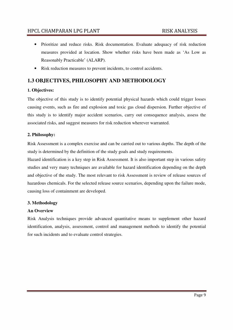
The methodology adopted for the QRA Study has been depicted in the Flow chart given below:
Fig 1.1: Methodology
HPCL CHAMPARAN – LPG PLANT RISK ANALYSIS
Page 11
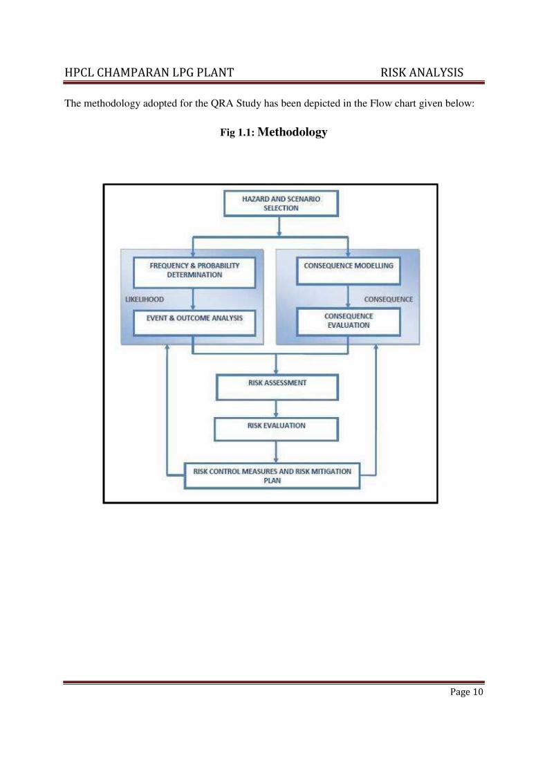
Fig 1.2 Site Plan
HPCL CHAMPARAN – LPG PLANT RISK ANALYSIS
Page 12
1.4 RISK ANALYSIS AND RISK ASSESSMENT.
The basic procedure in a risk analysis shall be as follows:
(a) Identify potential failures or incidents (including frequency)
(b) Calculate the quantity of material that may be released in each failure, estimate the
probability of such occurrences.
(c) Evaluate the consequences of such occurrences based on scenarios such as most
probable and worst case events.
(d) The combination of consequences and probability will allow the hazards to be ranked
in a logical fashion to indicate the zones of important risk. Criteria should then be
established by which the quantified level of risk may be considered acceptable to all
parties concerned.
(e) After assessing the risk “maximum tolerable criterion” must be defined and above
which the risk shall be regarded as intolerable. Whatever be the benefit level must be
reduced below this level.
(f) The risk should also be made “as low as reasonably practicable” (ALARP) and least
impacting the neighborhood.
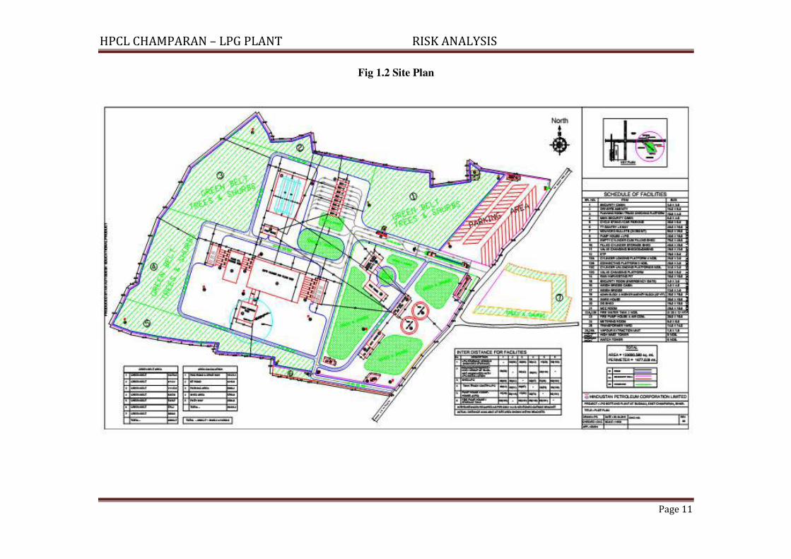
Fig 1.3:
While conducting the risk analysis, a quantitative determination of risk involves three major
steps:-
HPCL CHAMPARAN LPG PLANT RISK ANALYSIS
Page 13
1.5 QUANTITATIVE RISK ASSESSMENT
QRA study for, M/s. Hindustan Petroleum Corporation Ltd. has been carried out based
on data provided. The study has been carried out in accordance with the International
codes of practices using DNVGL-Phast Lite software.
The full terms of potential hazardous scenarios and consequence events associated with
the installation and operation was considered in the analysis. Based on the operations to
be carried at the plant, the Risk Analysis, affected distances and the damage of property
and population from the identified scenarios considering the Maximum Credible Loss
Scenario (MCLS) & Worst case scenario. Maximum credible loss scenarios have been
worked based on the inbuilt safety systems and protection measures to be provided for
the operation of the facility.
We have assumed Maximum credible loss scenario (MCLS) i.e. Nozzle failure and
Worst case Scenario i.e. catastrophic rupture as per the guidelines suggested by DNV –
UK. Similarly, maximum inventory at the time of failure is assumed.
1.6 USE OF QRA RESULTS:
The techniques used for risk prediction within the QRA have inherent uncertainties
associated with them due to the necessary simplifications required. In addition, QRA
incorporates a certain amount of subjective engineering judgment and the results are
subject to levels of uncertainty. For this reason, the results should not be used as the sole
basis for decision making and should not drive deviations from sound engineering
practice. The results should be used as a tool to aid engineering judgment and, if used in
this way, can provide valuable information during the decision making process.
The QRA results are dependent on the assumptions made in the calculations, which are
clearly documented throughout the following sections of this report. Conservative
assumptions have been used, which helps to remove the requirement for detailed analysis
of the uncertainty. The results show the significant contributions to the overall risk and
indicate where worthwhile gains may be achieved if further enhancement of safety is
deemed necessary.
HPCL CHAMPARAN LPG PLANT RISK ANALYSIS
Page 14
1.7 SOFTWARE USED
DNVGL - Phast Lite has been used for consequence analysis include discharge and
dispersion calculations.
1.8 Weather Category
One of the most important characteristics of atmosphere is its stability. Stability of
atmosphere is its tendency to resist vertical motion or to suppress existing turbulence.
This tendency directly influences the ability of atmosphere to disperse pollutants emitted
into it from the facilities. In most dispersion scenarios, the relevant atmospheric layer is
that nearest to the ground, varying in thickness from a few meters to a few thousand
meters. Turbulence induced by buoyancy forces in the atmosphere is closely related to
the vertical temperature gradient.
Temperature normally decreases with increasing height in the atmosphere. The rate at
which the temperature of air decreases with height is called Environmental Lapse Rate
(ELR). It will vary from time to time and from place to place. The atmosphere is said to
be stable, neutral or unstable according to ELR is less than, equal to or greater than Dry
Adiabatic Lapse Rate (DALR), which is a constant value of 0.98°C/100 meters.
Pas-quill stability parameter, based on Pas-quill – Gifford categorization, is such a
meteorological parameter, which describes the stability of atmosphere, i.e., the degree of
convective turbulence. Pas-quill has defined six stability classes ranging from `A'
(extremely unstable) to `F' (moderately stable). Wind speeds, intensity of solar radiation
(daytime insulation) and nighttime sky cover have been identified as prime factors
defining these stability categories.
When the atmosphere is unstable and wind speeds are moderate or high or gusty, rapid
dispersion of pollutants will occur. Under these conditions, pollutant concentrations in
air will be moderate or low and the material will be dispersed rapidly. When the
atmosphere is stable and wind speed is low, dispersion of material will be limited and
pollutant concentration in air will be high. In general, worst dispersion conditions (i.e.
contributing to greater hazard distances) occur during low wind speed and very stable
weather conditions.
HPCL CHAMPARAN LPG PLANT RISK ANALYSIS
Page 15
1.9 METHODOLOGY ADOPTED FOR CONSEQUENCE ANALYSIS
Consequences of loss of containment can lead to hazardous situation in any industry
handling potentially hazardous materials. Following factors govern the severity of
consequence of the loss of containment.
• Intrinsic properties; flammability, instability and toxicity.
• Dispersive energy; pressure, temperature and state of matter.
• Quantity present
• Environmental factors; topography and weather.
Consequence analysis and calculations are effectively performed by computer software
using models validated over a number of applications. Consequence modeling is carried
out by Phast Lite of DNV Software.
PHAST contains data for a large number of chemicals and allows definition of mixtures
of any of these chemicals in the required proportion. The calculations by PHAST involve
following steps for each modeled failure case:
• Run discharge calculations based on physical conditions and leak size.
• Model first stage of release (for each weather category).
• Determine vapor release rate by flashing of liquid and pool evaporation rate.
• Dispersion modeling taking into account weather conditions.
• In case of flammable release, calculate size of effect zone for fire and explosion.
1.10 HAZARDS OF MATERIALS
Definitions
The release of flammable gas or liquid can lead to different types of fire or explosion
scenarios. These depend on the material released, mechanism of release, temperature and
pressure of the material and the point of ignition. Types of flammable effects are as
follows:
Flash fire:
It occurs when a vapor cloud of flammable material burns. The cloud is typically ignited
on the edge and burns towards the release point. The duration of flash fire is very short
(seconds), but it may continue as jet fire if the release continues. The overpressures
generated by the combustion are not considered significant in terms of damage potential
to persons, equipment or structures. The major hazard from flash fire is direct flame
HPCL CHAMPARAN LPG PLANT RISK ANALYSIS
Page 16
impingement. Typically, the burn zone is defined as the area the vapor cloud covers out
to half of the LFL. This definition provides a conservative estimate, allowing for
fluctuations in modeling. Even where the concentration may be above the UFL, turbulent
induced combustion mixes the material with air and results in flash fire.
Jet FIRE:
Escaping jet of LPG from pressure vessels/piping, if ignited, cause a jet flame. The jet
flame direction and tilt depend on prevailing wind direction and velocity. Jet flames are
characterized as high-pressure release of gas from limited openings (e.g. due to small
leak in a vessel or broken drain valve). A fireball is an intense spherical fire resulting
from a sudden release of pressurized liquid or gas that is immediately ignited.
FIREBALL:
A combination of fire and explosion, sometimes referred as fireball, occurs with an
intense radiant heat emission in a relatively shorts time interval along with generation of
heavy pressure waves and flying fragments of the vessel. As implied by the term, the
phenomenon can occur within a vessel or tank in which a liquefied gas is kept at a
temperature above its atmospheric boiling point. If a pressure vessel fails as a result of a
weakening of its structure the contents are instantaneously released from the vessel as a
turbulent mixture of liquid and vapor, expanding rapidly and dispersing in air as a cloud.
When this cloud is ignited, a fireball occurs, causing enormous heat radiation intensity
within a few seconds. This heat intensity is sufficient to cause severe skin burns and
deaths at several hundred meters from the vessel, depending on the quantity of the gas
involved. A fireball therefore be caused by a physical impact on a vessel, for example
from a traffic accident with a road tanker or a derailment of, or it can be caused by fire
impinging upon or engulfing a vessel and thus weakening its structure.
Explosions are characterized by a shock-wave, which can cause damage to buildings,
breaking windows and ejecting missiles over distances of several hundred meters. The
injuries and damages are in the first place caused by the shock-wave of the explosion
itself. People are blown over or knocked down and buried under collapsed buildings or
injured by flying fragments.
The effects of the shock wave depend on factors like characteristics of the chemical,
quantity of the chemical in the vapor cloud etc. The peak pressures in an explosion,
therefore, vary between slight over-pressure and a few hundred kilopascals (KPa).
HPCL CHAMPARAN LPG PLANT RISK ANALYSIS
Page 17
Pressure of the shock-wave decreases rapidly with the increase in distance from the
source of the explosion.
Confined and unconfined vapor-cloud explosions:
Confined explosions are those that occur within some sort of containment such as vessel
or pipe work. Explosions in buildings also come under this category. Explosions that
occur in the open air are referred to as unconfined explosions and produce peak pressures
of only a few KPa. The peak pressures of confined explosions are generally higher and
may reach hundreds of KPa. All the examples given are vapor cloud explosions, which,
in some cases, lead to detonation due to the confinement of the gas cloud. It is difficult to
strictly distinguish between a fire and an explosion. Quite often a fire follows an
explosion and the casualties are caused by both phenomena.
1.11 FIRE AND EXPLOSION INDEX (F & EI)
F & EI is a rapid ranking method for identifying the degree of hazard. In preliminary
hazard analysis LPG are considered to have fire & Explosion hazards. The
application of F & EI would help to make a quick assessment of the nature and
quantification of the hazard in these areas. However, this does not provide precise
information.
Material factor (MF) of the material concerned, the General Process hazards and
Special Process Hazards associated with the product are taken into consideration while
computing, using standard procedure of awarding penalties based on storage,
handling & operating parameters.
As regards the storage area is concerned the major potential hazard rests with the
contents of LPG. In addition F & EI for complete storage area has been evaluated.
1.12 DOW F & EI HAZARD CLASSIFICATION
The F & EI calculation is used for estimating the damage that would probably result
from an accident in the plant. The following is the listing of F & EI values versus a
description of the degree of hazard that gives some relative idea of the severity of the F
& EI.
Computations & Evaluation of Fire Explosion Index:
The degree of hazard potential is identified based on the numerical value of FEI as per
following criteria:
HPCL CHAMPARAN LPG PLANT RISK ANALYSIS
Page 18
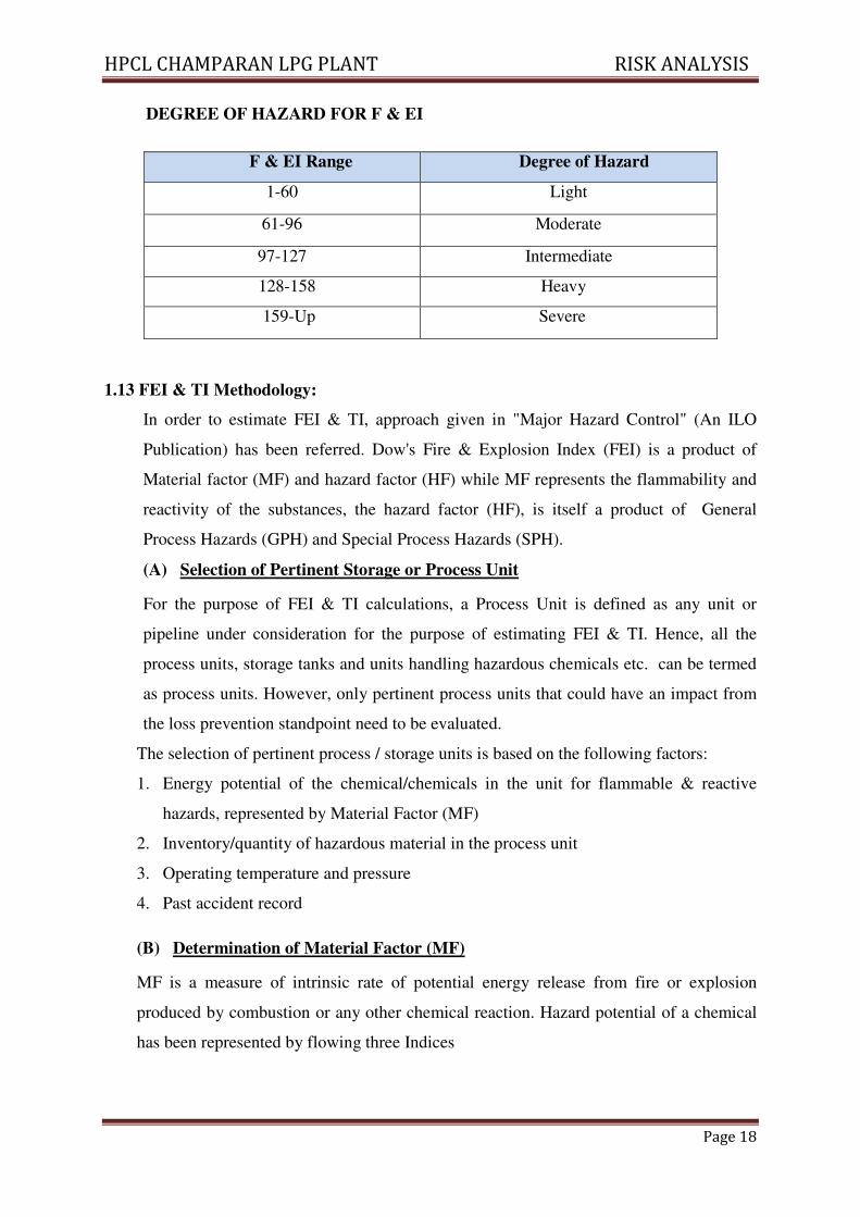
DEGREE OF HAZARD FOR F & EI
1.13 FEI & TI Methodology:
In order to estimate FEI & TI, approach given in "Major Hazard Control" (An ILO
Publication) has been referred. Dow's Fire & Explosion Index (FEI) is a product of
Material factor (MF) and hazard factor (HF) while MF represents the flammability and
reactivity of the substances, the hazard factor (HF), is itself a product of General
Process Hazards (GPH) and Special Process Hazards (SPH).
(A) Selection of Pertinent Storage or Process Unit
For the purpose of FEI & TI calculations, a Process Unit is defined as any unit or
pipeline under consideration for the purpose of estimating FEI & TI. Hence, all the
process units, storage tanks and units handling hazardous chemicals etc. can be termed
as process units. However, only pertinent process units that could have an impact from
the loss prevention standpoint need to be evaluated.
The selection of pertinent process / storage units is based on the following factors:
1. Energy potential of the chemical/chemicals in the unit for flammable & reactive
hazards, represented by Material Factor (MF)
2. Inventory/quantity of hazardous material in the process unit
3. Operating temperature and pressure
4. Past accident record
(B) Determination of Material Factor (MF)
MF is a measure of intrinsic rate of potential energy release from fire or explosion
produced by combustion or any other chemical reaction. Hazard potential of a chemical
has been represented by flowing three Indices
F & EI Range Degree of Hazard
1-60 Light
61-96 Moderate
97-127 Intermediate
128-158 Heavy
159-Up Severe
HPCL CHAMPARAN LPG PLANT RISK ANALYSIS
Page 19
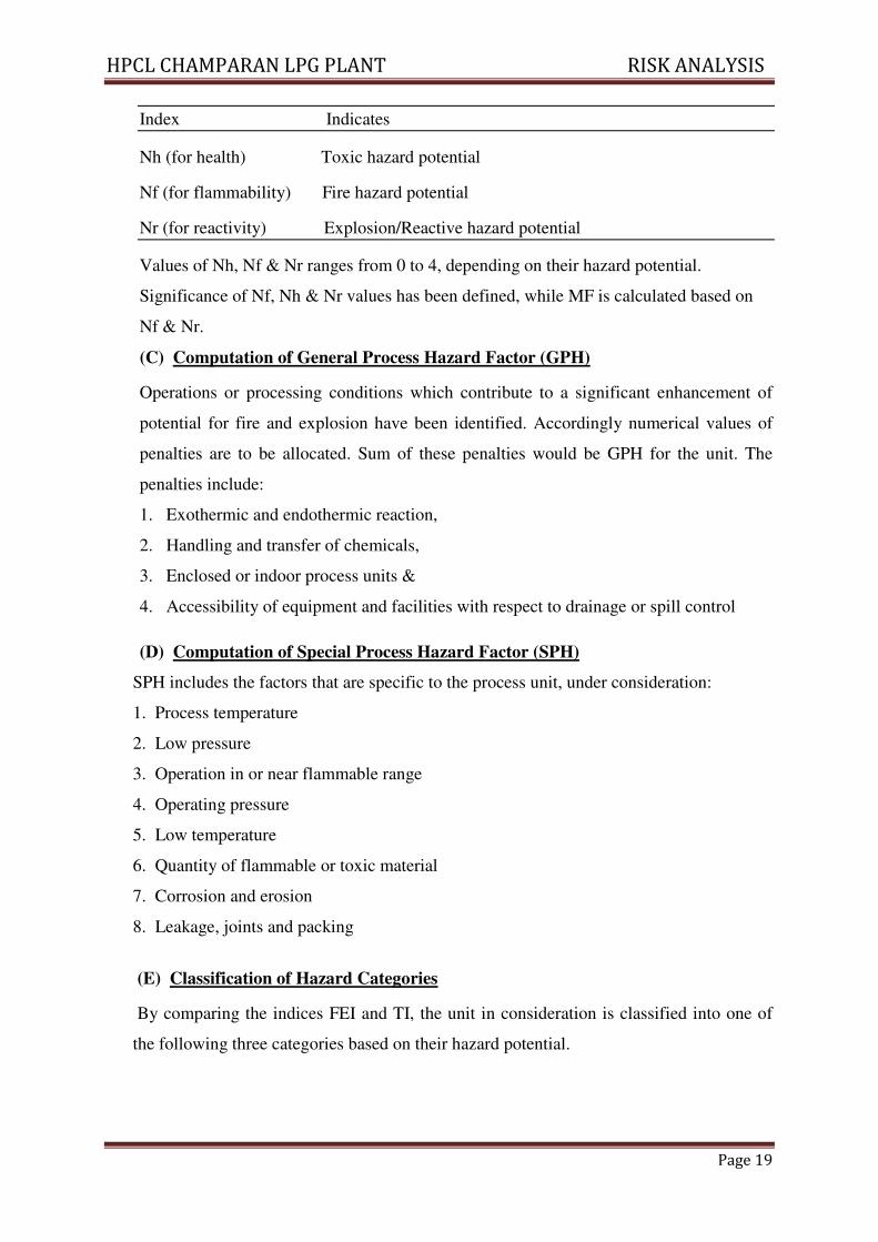
Index Indicates
Nh (for health) Toxic hazard potential
Nf (for flammability) Fire hazard potential
Nr (for reactivity) Explosion/Reactive hazard potential
Values of Nh, Nf & Nr ranges from 0 to 4, depending on their hazard potential.
Significance of Nf, Nh & Nr values has been defined, while MF is calculated based on
Nf & Nr.
(C) Computation of General Process Hazard Factor (GPH)
Operations or processing conditions which contribute to a significant enhancement of
potential for fire and explosion have been identified. Accordingly numerical values of
penalties are to be allocated. Sum of these penalties would be GPH for the unit. The
penalties include:
1. Exothermic and endothermic reaction,
2. Handling and transfer of chemicals,
3. Enclosed or indoor process units &
4. Accessibility of equipment and facilities with respect to drainage or spill control
(D) Computation of Special Process Hazard Factor (SPH)
SPH includes the factors that are specific to the process unit, under consideration:
1. Process temperature
2. Low pressure
3. Operation in or near flammable range
4. Operating pressure
5. Low temperature
6. Quantity of flammable or toxic material
7. Corrosion and erosion
8. Leakage, joints and packing
(E) Classification of Hazard Categories
By comparing the indices FEI and TI, the unit in consideration is classified into one of
the following three categories based on their hazard potential.
HPCL CHAMPARAN LPG PLANT RISK ANALYSIS
Page 20
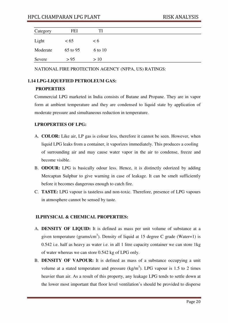
Category FEI TI
Light < 65 < 6
Moderate 65 to 95 6 to 10
Severe > 95 > 10
NATIONAL FIRE PROTECTION AGENCY (NFPA, US) RATINGS:
1.14 LPG-LIQUEFIED PETROLEUM GAS:
PROPERTIES
Commercial LPG marketed in India consists of Butane and Propane. They are in vapor
form at ambient temperature and they are condensed to liquid state by application of
moderate pressure and simultaneous reduction in temperature.
I.PROPERTIES OF LPG:
A. COLOR: Like air, LP gas is colour less, therefore it cannot be seen. However, when
liquid LPG leaks from a container, it vaporizes immediately. This produces a cooling
of surrounding air and may cause water vapor in the air to condense, freeze and
become visible.
B. ODOUR: LPG is basically odour less. Hence, it is distinctly odorized by adding
Mercaptan Sulphur to give warning in case of leakage. It can be smelt sufficiently
before it becomes dangerous enough to catch fire.
C. TASTE: LPG vapour is tasteless and non-toxic. Therefore, presence of LPG vapours
in atmosphere cannot be sensed by taste.
II.PHYSICAL & CHEMICAL PROPERTIES:
A. DENSITY OF LIQUID: It is defined as mass per unit volume of substance at a
given temperature (grams/cm3). Density of liquid at 15 degree C grade (Water=1) is
0.542 i.e. half as heavy as water i.e. in all 1 litre capacity container we can store 1kg
of water whereas we can store 0.542 kg of LPG only.
B. DENSITY OF VAPOUR: It is defined as mass of a substance occupying a unit
volume at a stated temperature and pressure (kg/m3). LPG vapour is 1.5 to 2 times
heavier than air. As a result of this property, any leakage LPG tends to settle down at
the lower most important that floor level ventilation’s should be provided to disperse
HPCL CHAMPARAN LPG PLANT RISK ANALYSIS
Page 21
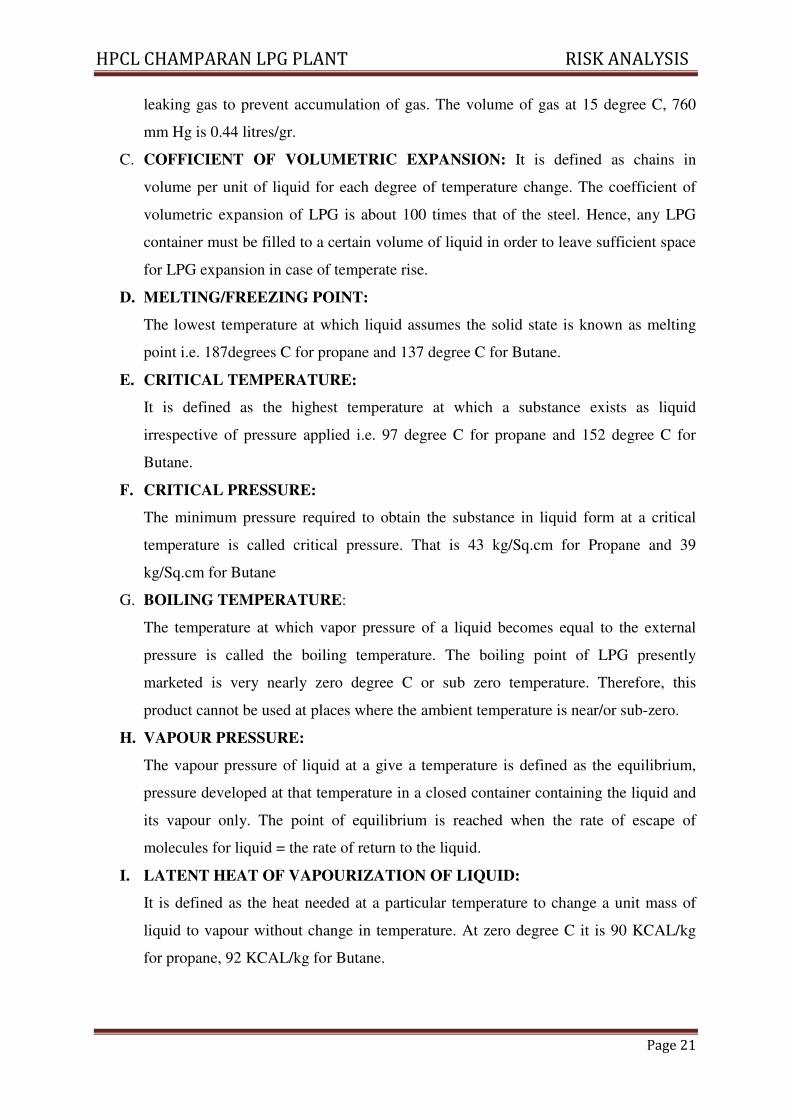
leaking gas to prevent accumulation of gas. The volume of gas at 15 degree C, 760
mm Hg is 0.44 litres/gr.
C. COFFICIENT OF VOLUMETRIC EXPANSION: It is defined as chains in
volume per unit of liquid for each degree of temperature change. The coefficient of
volumetric expansion of LPG is about 100 times that of the steel. Hence, any LPG
container must be filled to a certain volume of liquid in order to leave sufficient space
for LPG expansion in case of temperate rise.
D. MELTING/FREEZING POINT:
The lowest temperature at which liquid assumes the solid state is known as melting
point i.e. 187degrees C for propane and 137 degree C for Butane.
E. CRITICAL TEMPERATURE:
It is defined as the highest temperature at which a substance exists as liquid
irrespective of pressure applied i.e. 97 degree C for propane and 152 degree C for
Butane.
F. CRITICAL PRESSURE:
The minimum pressure required to obtain the substance in liquid form at a critical
temperature is called critical pressure. That is 43 kg/Sq.cm for Propane and 39
kg/Sq.cm for Butane
G. BOILING TEMPERATURE:
The temperature at which vapor pressure of a liquid becomes equal to the external
pressure is called the boiling temperature. The boiling point of LPG presently
marketed is very nearly zero degree C or sub zero temperature. Therefore, this
product cannot be used at places where the ambient temperature is near/or sub-zero.
H. VAPOUR PRESSURE:
The vapour pressure of liquid at a give a temperature is defined as the equilibrium,
pressure developed at that temperature in a closed container containing the liquid and
its vapour only. The point of equilibrium is reached when the rate of escape of
molecules for liquid = the rate of return to the liquid.
I. LATENT HEAT OF VAPOURIZATION OF LIQUID:
It is defined as the heat needed at a particular temperature to change a unit mass of
liquid to vapour without change in temperature. At zero degree C it is 90 KCAL/kg
for propane, 92 KCAL/kg for Butane.
HPCL CHAMPARAN LPG PLANT RISK ANALYSIS
Page 22
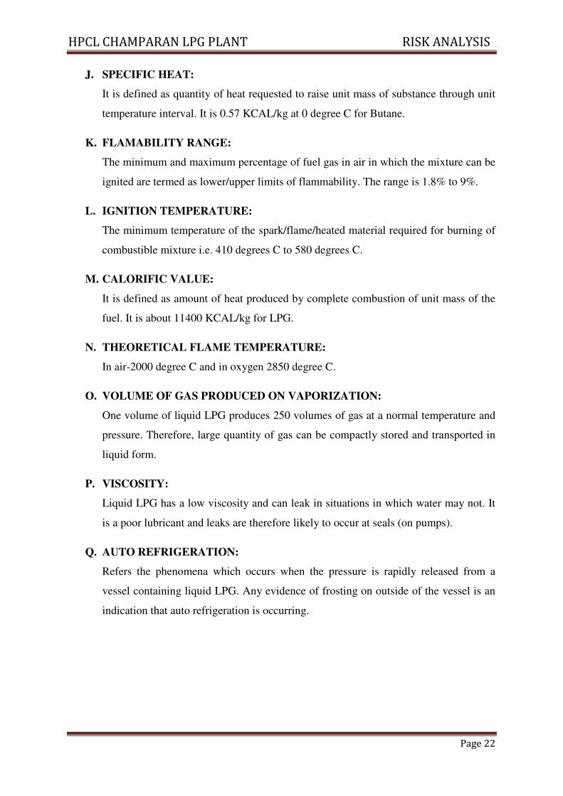
J. SPECIFIC HEAT:
It is defined as quantity of heat requested to raise unit mass of substance through unit
temperature interval. It is 0.57 KCAL/kg at 0 degree C for Butane.
K. FLAMABILITY RANGE:
The minimum and maximum percentage of fuel gas in air in which the mixture can be
ignited are termed as lower/upper limits of flammability. The range is 1.8% to 9%.
L. IGNITION TEMPERATURE:
The minimum temperature of the spark/flame/heated material required for burning of
combustible mixture i.e. 410 degrees C to 580 degrees C.
M. CALORIFIC VALUE:
It is defined as amount of heat produced by complete combustion of unit mass of the
fuel. It is about 11400 KCAL/kg for LPG.
N. THEORETICAL FLAME TEMPERATURE:
In air-2000 degree C and in oxygen 2850 degree C.
O. VOLUME OF GAS PRODUCED ON VAPORIZATION:
One volume of liquid LPG produces 250 volumes of gas at a normal temperature and
pressure. Therefore, large quantity of gas can be compactly stored and transported in
liquid form.
P. VISCOSITY:
Liquid LPG has a low viscosity and can leak in situations in which water may not. It
is a poor lubricant and leaks are therefore likely to occur at seals (on pumps).
Q. AUTO REFRIGERATION:
Refers the phenomena which occurs when the pressure is rapidly released from a
vessel containing liquid LPG. Any evidence of frosting on outside of the vessel is an
indication that auto refrigeration is occurring.
HPCL CHAMPARAN LPG PLANT RISK ANALYSIS
Page 23
1.15 Liquefied Petroleum Gas (LPG):
Inferences
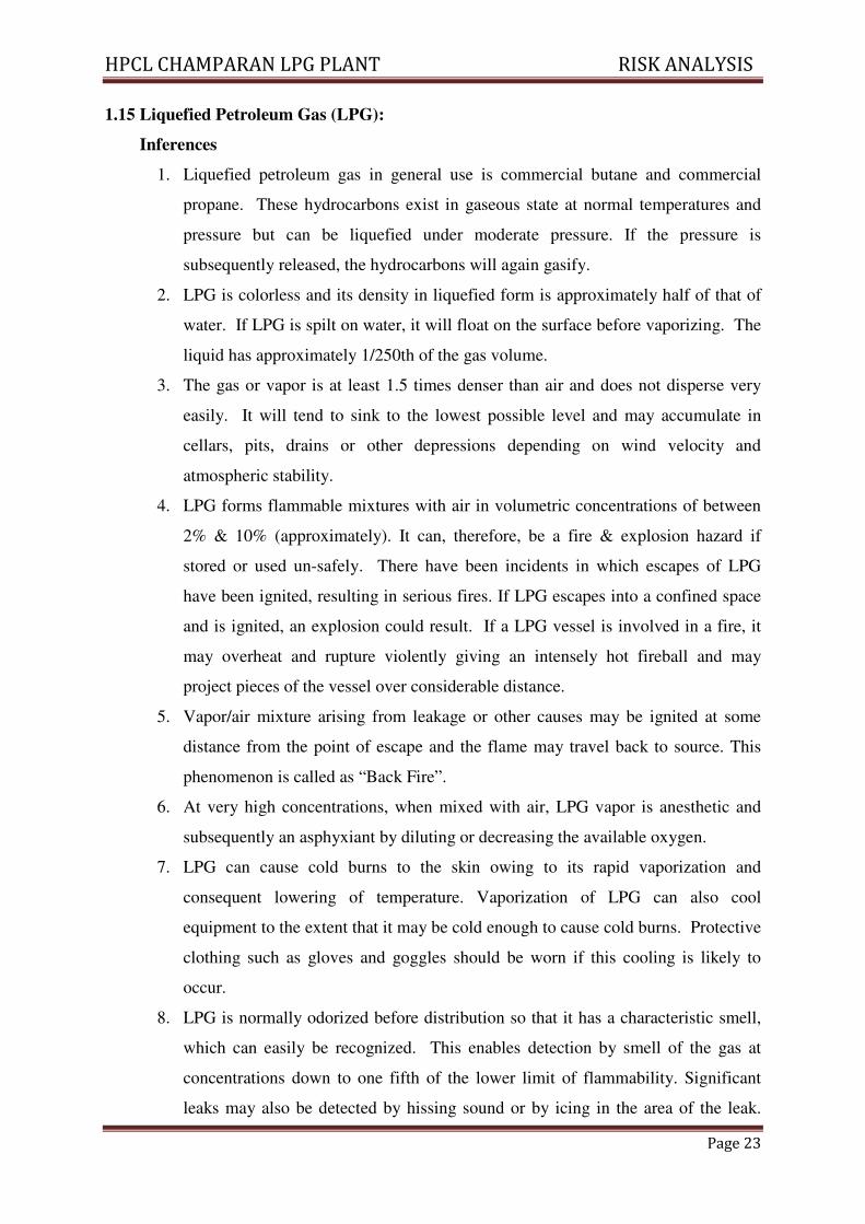
1. Liquefied petroleum gas in general use is commercial butane and commercial
propane. These hydrocarbons exist in gaseous state at normal temperatures and
pressure but can be liquefied under moderate pressure. If the pressure is
subsequently released, the hydrocarbons will again gasify.
2. LPG is colorless and its density in liquefied form is approximately half of that of
water. If LPG is spilt on water, it will float on the surface before vaporizing. The
liquid has approximately 1/250th of the gas volume.
3. The gas or vapor is at least 1.5 times denser than air and does not disperse very
easily. It will tend to sink to the lowest possible level and may accumulate in
cellars, pits, drains or other depressions depending on wind velocity and
atmospheric stability.
4. LPG forms flammable mixtures with air in volumetric concentrations of between
2% & 10% (approximately). It can, therefore, be a fire & explosion hazard if
stored or used un-safely. There have been incidents in which escapes of LPG
have been ignited, resulting in serious fires. If LPG escapes into a confined space
and is ignited, an explosion could result. If a LPG vessel is involved in a fire, it
may overheat and rupture violently giving an intensely hot fireball and may
project pieces of the vessel over considerable distance.
5. Vapor/air mixture arising from leakage or other causes may be ignited at some
distance from the point of escape and the flame may travel back to source. This
phenomenon is called as “Back Fire”.
6. At very high concentrations, when mixed with air, LPG vapor is anesthetic and
subsequently an asphyxiant by diluting or decreasing the available oxygen.
7. LPG can cause cold burns to the skin owing to its rapid vaporization and
consequent lowering of temperature. Vaporization of LPG can also cool
equipment to the extent that it may be cold enough to cause cold burns. Protective
clothing such as gloves and goggles should be worn if this cooling is likely to
occur.
8. LPG is normally odorized before distribution so that it has a characteristic smell,
which can easily be recognized. This enables detection by smell of the gas at
concentrations down to one fifth of the lower limit of flammability. Significant
leaks may also be detected by hissing sound or by icing in the area of the leak.
HPCL CHAMPARAN LPG PLANT RISK ANALYSIS
Page 24
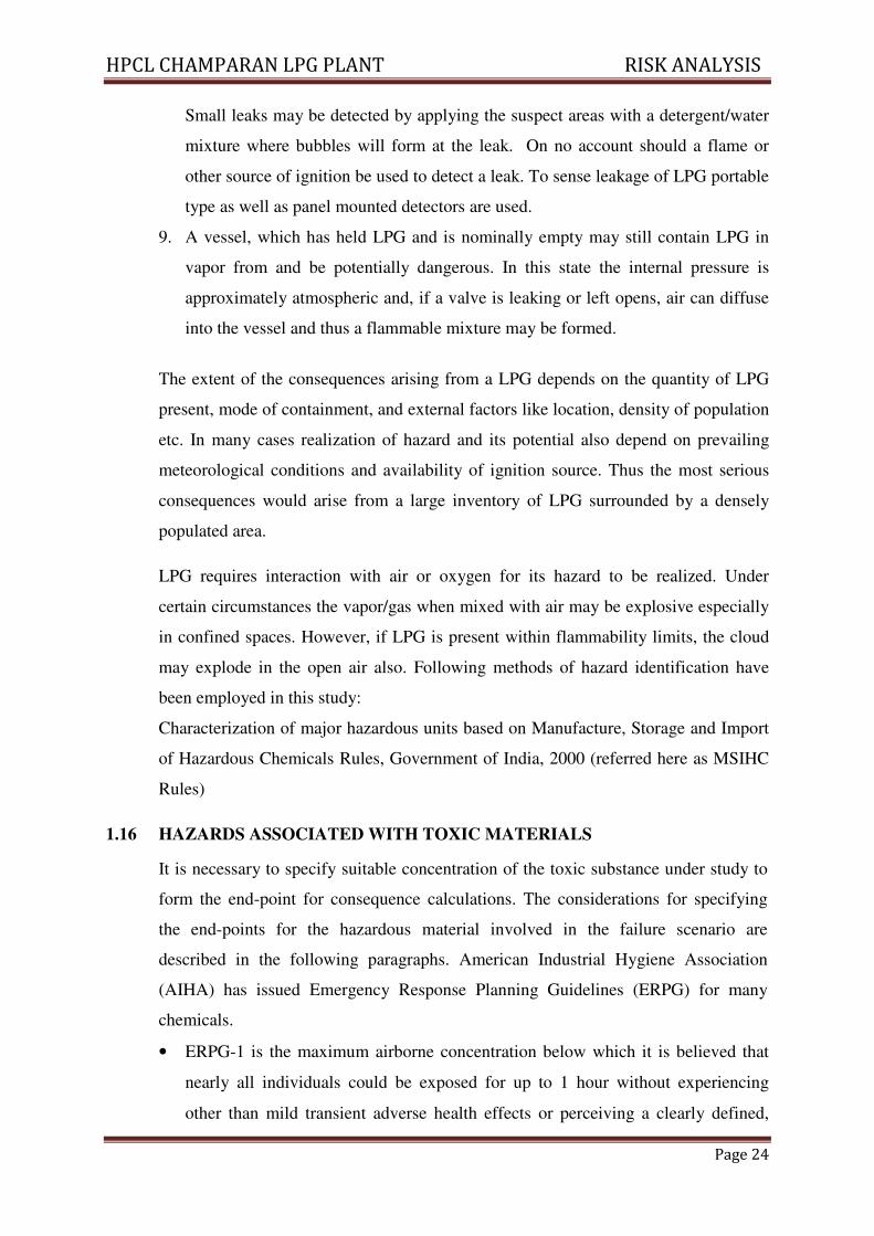
Small leaks may be detected by applying the suspect areas with a detergent/water
mixture where bubbles will form at the leak. On no account should a flame or
other source of ignition be used to detect a leak. To sense leakage of LPG portable
type as well as panel mounted detectors are used.
9. A vessel, which has held LPG and is nominally empty may still contain LPG in
vapor from and be potentially dangerous. In this state the internal pressure is
approximately atmospheric and, if a valve is leaking or left opens, air can diffuse
into the vessel and thus a flammable mixture may be formed.
The extent of the consequences arising from a LPG depends on the quantity of LPG
present, mode of containment, and external factors like location, density of population
etc. In many cases realization of hazard and its potential also depend on prevailing
meteorological conditions and availability of ignition source. Thus the most serious
consequences would arise from a large inventory of LPG surrounded by a densely
populated area.
LPG requires interaction with air or oxygen for its hazard to be realized. Under
certain circumstances the vapor/gas when mixed with air may be explosive especially
in confined spaces. However, if LPG is present within flammability limits, the cloud
may explode in the open air also. Following methods of hazard identification have
been employed in this study:
Characterization of major hazardous units based on Manufacture, Storage and Import
of Hazardous Chemicals Rules, Government of India, 2000 (referred here as MSIHC
Rules)
1.16 HAZARDS ASSOCIATED WITH TOXIC MATERIALS
It is necessary to specify suitable concentration of the toxic substance under study to
form the end-point for consequence calculations. The considerations for specifying
the end-points for the hazardous material involved in the failure scenario are
described in the following paragraphs. American Industrial Hygiene Association
(AIHA) has issued Emergency Response Planning Guidelines (ERPG) for many
chemicals.
• ERPG-1 is the maximum airborne concentration below which it is believed that
nearly all individuals could be exposed for up to 1 hour without experiencing
other than mild transient adverse health effects or perceiving a clearly defined,
HPCL CHAMPARAN LPG PLANT RISK ANALYSIS
Page 25
objectionable odour.
• ERPG-2 is the maximum airborne concentration below which it is believed that
nearly all individuals could be exposed for up to 1 hour without experiencing or
developing irreversible or other serious health effects or symptoms, which could
impair an individual's ability to take protective action.
• ERPG-3 is the maximum airborne concentration below which it is believed that
nearly all individuals could be exposed for up to 1 hour without experiencing or
developing life-threatening health effects.
Toxic limit values as Immediately Dangerous to Life or Health (IDLH) concentrations
are issued by US National Institute for Occupational Safety and Health (NIOSH). An
IDLH level represents the maximum airborne concentration of a substance to which a
healthy male worker can be exposed as long as 30 minutes and still be able to escape
without loss of life or irreversible organ system damage. IDLH values also take into
consideration acute toxic reactions such as severe eye irritation, which could prevent
escape. IDLH values are used in selection of breathing apparatus.
TLV: Threshold Limit Value – is the permitted level of exposure for a given period
on a weighted average basis (usually 8 hrs for 5 days in a week).
STEL: A Short Term Exposure Limit (STEL) is defined by ACGIH as the
concentration to which workers can be exposed continuously for a short period of
time without suffering from:
• Irritation
• chronic or irreversible tissue damage
• Narcosis of sufficient degree to increase the likelihood of accidental injury, impair
self-rescue or materially reduce work efficiency.
It is permitted Short Time Exposure Limit usually for a 15-minute exposure
1.17 Damage Criteria
Damage estimates due to thermal radiations and overpressure have been arrived at by
taking in to consideration the published literature on the subject. The consequences can
then be visualized by the superimposing the damage effects zones on the proposed plan
site and identifying the elements within the project site as well as in the neighboring
environment, which might be adversely affected, should one or more hazards materialize
in real life.
HPCL CHAMPARAN LPG PLANT RISK ANALYSIS
Page 26
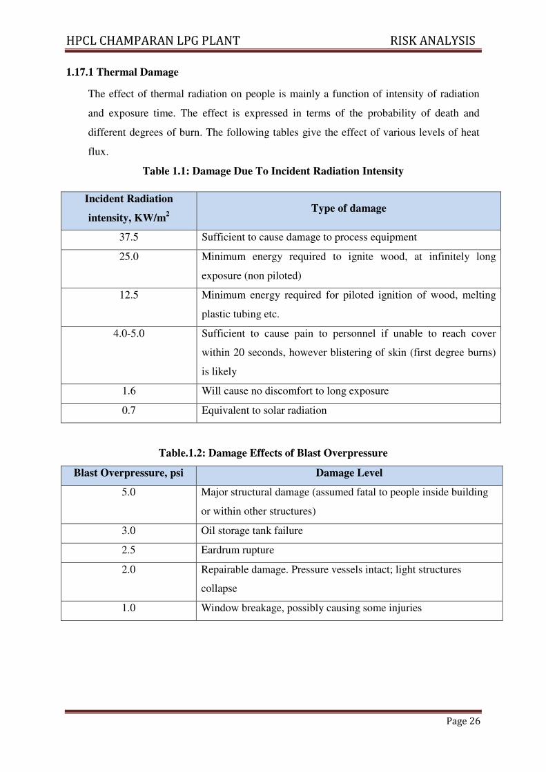
1.17.1 Thermal Damage
The effect of thermal radiation on people is mainly a function of intensity of radiation
and exposure time. The effect is expressed in terms of the probability of death and
different degrees of burn. The following tables give the effect of various levels of heat
flux.
Table 1.1: Damage Due To Incident Radiation Intensity
Incident Radiation
intensity, KW/m2
Type of damage
37.5 Sufficient to cause damage to process equipment
25.0 Minimum energy required to ignite wood, at infinitely long
exposure (non piloted)
12.5 Minimum energy required for piloted ignition of wood, melting
plastic tubing etc.
4.0-5.0 Sufficient to cause pain to personnel if unable to reach cover
within 20 seconds, however blistering of skin (first degree burns)
is likely
1.6 Will cause no discomfort to long exposure
0.7 Equivalent to solar radiation
Table.1.2: Damage Effects of Blast Overpressure
Blast Overpressure, psi Damage Level
5.0 Major structural damage (assumed fatal to people inside building
or within other structures)
3.0 Oil storage tank failure
2.5 Eardrum rupture
2.0 Repairable damage. Pressure vessels intact; light structures
collapse
1.0 Window breakage, possibly causing some injuries
HPCL CHAMPARAN LPG PLANT RISK ANALYSIS
Page 27
1.18 Selected Failure Cases
Earlier, it was the practice to select a particular item in a unit as failure scenario, e.g.
rupture of reactor outlet pipe. Such selection is normally subjective on following
parameters:
• Properties of material namely Toxic or Flammable.
• The likely severity of consequence in the event of accidental release based on
inventory, operated pressure & operated temperature.
• The probability of failure of various equipments such as valves, flanges, pipe,
pressure vessels etc. used in the plant.
The scenarios are considered to be confined to those equipment failures which involve
the leakage of flammable or toxic products, of which the frequency of occurrence and
the severity of the consequences have been taken into consideration and which may
have a low probability of early detection.
Taking this factor into consideration, a list of selected failure cases was prepared based
on process knowledge, inventory, engineering judgment, and experience, past incidents
associated with such facilities and considering the general mechanisms for loss of
containment. Cases have been identified for the consequence analysis.
Consequence analysis and calculations are effectively performed by computer software
using models validated over a number of applications. Consequence modeling is carried
out by PHAST of DNV Software, UK.
PHAST uses the Unified Dispersion Model (UDM) capable of describing a wide range of
types of accidental releases. The Model uses a particularly flexible form, allowing for
sharp-edged profiles, which become more diffuse downwind.
PHAST contains data for a large number of chemicals and allows definition of mixtures
of any of these chemicals in the required proportion.
1.19 Effect of Release
When hazardous material is released to atmosphere due to any reason, a vapor cloud is
formed. Direct cloud formation occurs when a gaseous or flashing liquid escapes to the
atmosphere. Release of hydrocarbons and toxic compounds to atmosphere may usually
HPCL CHAMPARAN LPG PLANT RISK ANALYSIS
Page 28
lead to the following:
a) Dispersion of hydrocarbon vapor with wind till it reaches its lower flammability limit
(LFL) or finds a source of ignition before reaching LFL, which will result in a flash
fire or explosion.
b) Spillage of liquid hydrocarbons will result in a pool of liquid, which will evaporate
taking heat from the surface, forming a flammable atmosphere above it. Ignition of
this pool will result in pool fire causing thermal radiation hazards.
c) Lighter hydrocarbon vapor or Hydrogen disperses rapidly in the downwind direction,
being lighter than air. But comparatively heavier hydrocarbon vapor cloud like that of
LPG, propane will travel downwind along the ground. If it encounters an ignition
source before it is dispersed below the LFL, explosion of an unconfined vapor cloud
will generate blast waves of different intensities.
d) A fireball occurs when a vessel containing a highly volatile liquid (e.g. LPG,
Propylene etc) fails and the released large mass of vapor cloud gets ignited
immediately. It has damage potential due to high intensity of radiation and generation
of the overpressure waves, causing large-scale damage to nearby equipment and
structures.
e) Catastrophic failure of tanks/ pressurized vessels, rotary equipment and valves etc.
can result in equipment fragments flying and hitting other equipment of the plant.
f) Release of toxic compounds results in the toxic vapour cloud traveling over long
distances, affecting a large area, before it gets sufficiently diluted to harmless
concentration in the atmosphere.
g) The material is in two phases inside the containment - liquid & vapor. Depending on
the location of the leak liquid or vapor will be released from the containment. If
vapor is released a vapor cloud will form by the mixing of the vapor and air. The
size of the vapor cloud will depend on the rate of release, wind speed; wind direction
& atmospheric stability will determine the dispersion and movement of the vapor
cloud.
h) If liquid is released there will be some flashing as the boiling point of liquid is below
the ambient temperature. The vapor formed by immediate flashing will behave as
vapors release. The liquid will fall on the ground forming a pool. There will be
vaporization from the pool due to the heat gained from the atmosphere & ground.
There will be dispersion and movement of vapor cloud formed by evaporation of
HPCL CHAMPARAN LPG PLANT RISK ANALYSIS
Page 29
liquid.
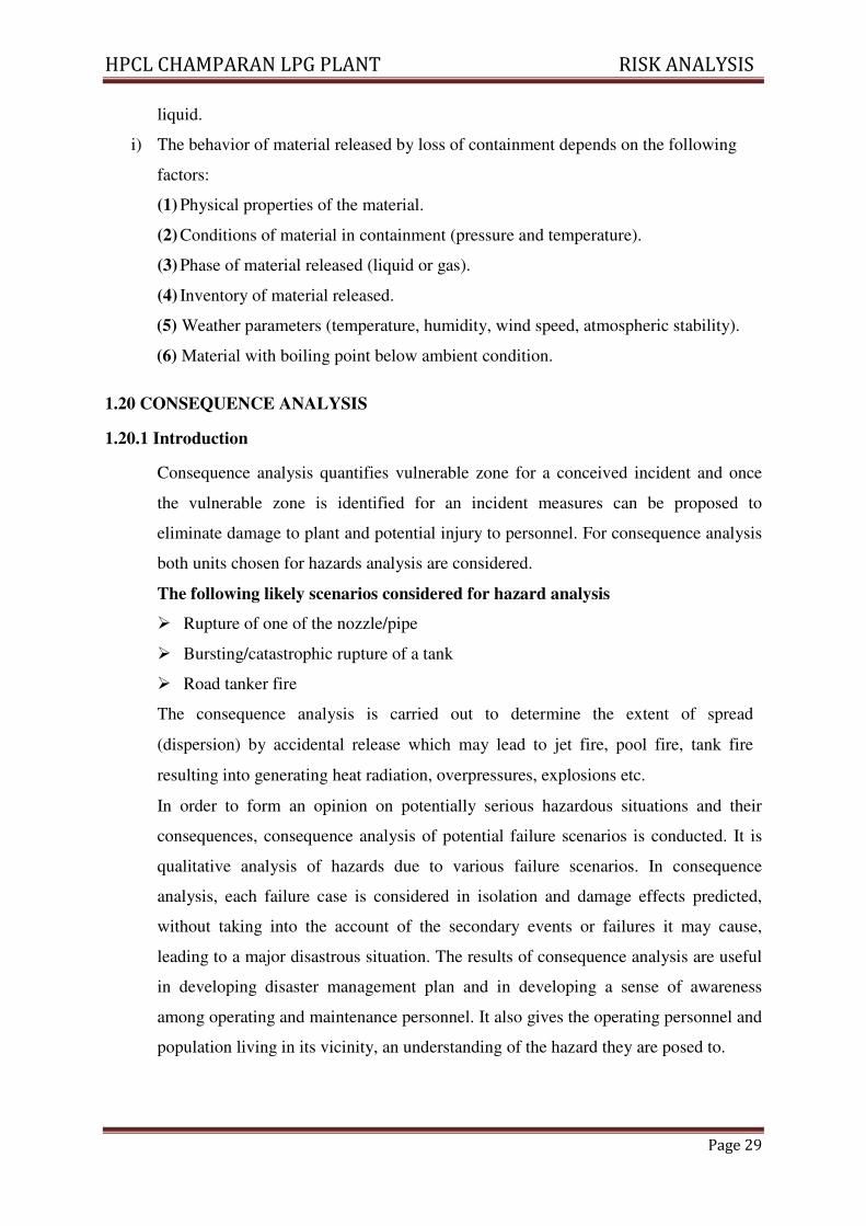
i) The behavior of material released by loss of containment depends on the following
factors:
(1) Physical properties of the material.
(2) Conditions of material in containment (pressure and temperature).
(3) Phase of material released (liquid or gas).
(4) Inventory of material released.
(5) Weather parameters (temperature, humidity, wind speed, atmospheric stability).
(6) Material with boiling point below ambient condition.
1.20 CONSEQUENCE ANALYSIS
1.20.1 Introduction
Consequence analysis quantifies vulnerable zone for a conceived incident and once
the vulnerable zone is identified for an incident measures can be proposed to
eliminate damage to plant and potential injury to personnel. For consequence analysis
both units chosen for hazards analysis are considered.
The following likely scenarios considered for hazard analysis
� Rupture of one of the nozzle/pipe
� Bursting/catastrophic rupture of a tank
� Road tanker fire
The consequence analysis is carried out to determine the extent of spread
(dispersion) by accidental release which may lead to jet fire, pool fire, tank fire
resulting into generating heat radiation, overpressures, explosions etc.
In order to form an opinion on potentially serious hazardous situations and their
consequences, consequence analysis of potential failure scenarios is conducted. It is
qualitative analysis of hazards due to various failure scenarios. In consequence
analysis, each failure case is considered in isolation and damage effects predicted,
without taking into the account of the secondary events or failures it may cause,
leading to a major disastrous situation. The results of consequence analysis are useful
in developing disaster management plan and in developing a sense of awareness
among operating and maintenance personnel. It also gives the operating personnel and
population living in its vicinity, an understanding of the hazard they are posed to.
HPCL CHAMPARAN LPG PLANT
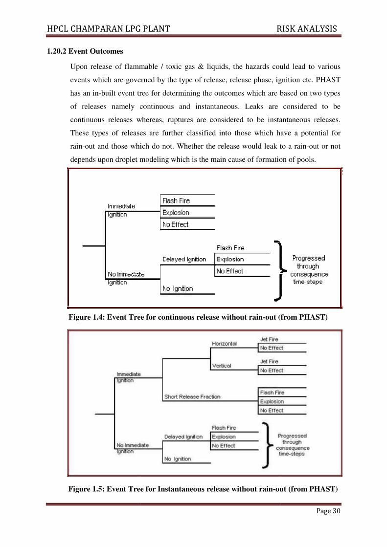
1.20.2 Event Outcomes
Upon release of flammable / toxic gas &
events which are governed by the type of release, release phase, ignition etc. PHAST
has an in-built event tree for determining the outcomes which are based on two types
of releases namely continuous and instanta
continuous releases whereas, ruptures are considered to be instantaneous releases.
These types of releases are further classified into those which have a potential for
rain-out and those which do not. Whether the release w
depends upon droplet modeling which is the main cause of formation of pools.
Figure 1.4: Event Tree for continuous release without rain
Figure 1.5: Event Tree for Instantaneous release without rain
LPG PLANT RISK ANALYSIS
Upon release of flammable / toxic gas & liquids, the hazards could lead to various
events which are governed by the type of release, release phase, ignition etc. PHAST
built event tree for determining the outcomes which are based on two types
of releases namely continuous and instantaneous. Leaks are considered to be
continuous releases whereas, ruptures are considered to be instantaneous releases.
These types of releases are further classified into those which have a potential for
out and those which do not. Whether the release would leak to a rain
depends upon droplet modeling which is the main cause of formation of pools.
: Event Tree for continuous release without rain-out (from PHAST)
Tree for Instantaneous release without rain-out (from PHAST)
RISK ANALYSIS
Page 30
liquids, the hazards could lead to various
events which are governed by the type of release, release phase, ignition etc. PHAST
built event tree for determining the outcomes which are based on two types
neous. Leaks are considered to be
continuous releases whereas, ruptures are considered to be instantaneous releases.
These types of releases are further classified into those which have a potential for
ould leak to a rain-out or not
depends upon droplet modeling which is the main cause of formation of pools.
out (from PHAST)
out (from PHAST)
HPCL CHAMPARAN LPG PLANT
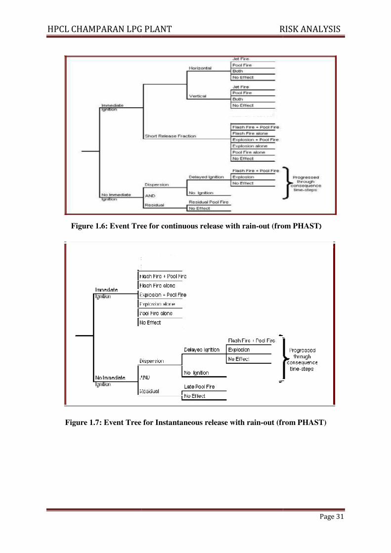
Figure 1.6: Event Tree for continuous release with rain
Figure 1.7: Event Tree for Instantaneous release with rain
LPG PLANT RISK ANALYSIS
: Event Tree for continuous release with rain-out (from PHAST
: Event Tree for Instantaneous release with rain-out (from PHAST)
RISK ANALYSIS
Page 31
out (from PHAST)
(from PHAST)
HPCL CHAMPARAN LPG PLANT RISK ANALYSIS
Page 32
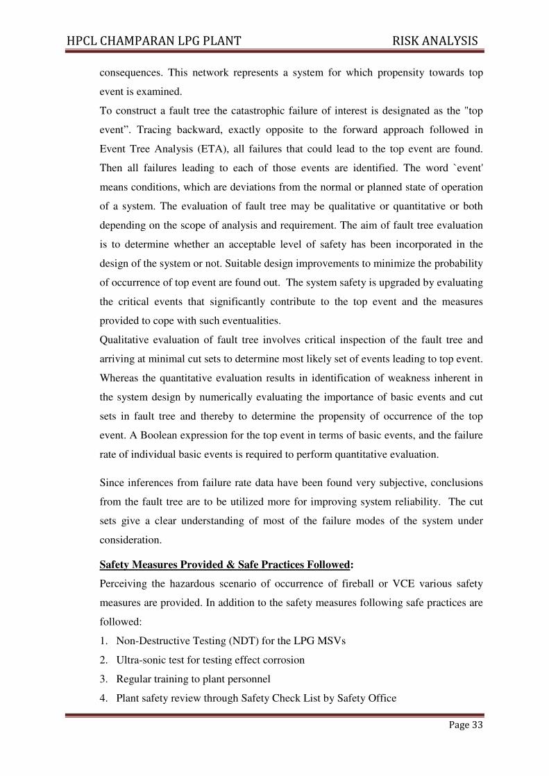
1.20.3 Event Tree Analysis to Define Outcome of Release
Different outcomes of a leakage or catastrophic failure are possible depending on if
and when ignition occurs and the consequences thereupon. ETA considers various
possibilities such as immediate or delayed ignition for the different outcomes to
occur. From ETA, following incident outcomes and the pathways are identified:
1. Fireball due to immediate ignition of an instantaneous escape of LPG from any
MSV or road tanker
2. Flare or Jet fire due to immediate ignition of a continuous release of LPG from any
MSV or any LPG handling unit and escalating into a fireball due to flame
impingement or over heating
3. Delayed ignition of a vapor cloud formed due to continuous release of LPG from
any MSV or any LPG handling unit resulting in `back fire' and escalation of the
event in to a fireball.
4. Confined or Unconfined VCE due to delayed ignition of a vapor cloud formed due
to continuous or an instantaneous release of LPG from any MSV or any LPG
handling unit .
ETA diagrams for various modes of failures of storage vessels for pressurized
liquefied gas, i.e. LPG has also been developed for conditions such as overfilling,
over-pressure and remote incidents like missile, lightening or bomb attack and earth
quake. The resultant rupture of vessels or leak incidents has been identified. The
outcomes of such accidents are also been identified in ETA. These are depicted in for
Pressurized Liquefied gases. Scenarios pertaining to over-pressure and overfilling are
most credible.
1.20.4 Fault Tree Analysis to Explore Propensity for Occurrence of the Top Event
In a system such as LPG Import Terminal it is important to analyze the possible
mechanisms of failure and to perform probabilistic analysis for the expected rate of
such failures. A technique like Fault Tree Analysis (FTA) can suitably be used for
this purpose.
Any system represented by a fault tree has components that operate in series or
parallel, with the contribution of the two being most frequent. These components are
studied for their failure and the possible causes are linked together through logical
gates. Thus a complete network is formed using logical gates for different causes and
HPCL CHAMPARAN LPG PLANT RISK ANALYSIS
Page 33
consequences. This network represents a system for which propensity towards top
event is examined.
To construct a fault tree the catastrophic failure of interest is designated as the "top
event”. Tracing backward, exactly opposite to the forward approach followed in
Event Tree Analysis (ETA), all failures that could lead to the top event are found.
Then all failures leading to each of those events are identified. The word `event'
means conditions, which are deviations from the normal or planned state of operation
of a system. The evaluation of fault tree may be qualitative or quantitative or both
depending on the scope of analysis and requirement. The aim of fault tree evaluation
is to determine whether an acceptable level of safety has been incorporated in the
design of the system or not. Suitable design improvements to minimize the probability
of occurrence of top event are found out. The system safety is upgraded by evaluating
the critical events that significantly contribute to the top event and the measures
provided to cope with such eventualities.
Qualitative evaluation of fault tree involves critical inspection of the fault tree and
arriving at minimal cut sets to determine most likely set of events leading to top event.
Whereas the quantitative evaluation results in identification of weakness inherent in
the system design by numerically evaluating the importance of basic events and cut
sets in fault tree and thereby to determine the propensity of occurrence of the top
event. A Boolean expression for the top event in terms of basic events, and the failure
rate of individual basic events is required to perform quantitative evaluation.
Since inferences from failure rate data have been found very subjective, conclusions
from the fault tree are to be utilized more for improving system reliability. The cut
sets give a clear understanding of most of the failure modes of the system under
consideration.
Safety Measures Provided & Safe Practices Followed:
Perceiving the hazardous scenario of occurrence of fireball or VCE various safety
measures are provided. In addition to the safety measures following safe practices are
followed:
1. Non-Destructive Testing (NDT) for the LPG MSVs
2. Ultra-sonic test for testing effect corrosion
3. Regular training to plant personnel
4. Plant safety review through Safety Check List by Safety Office
HPCL CHAMPARAN LPG PLANT RISK ANALYSIS
Page 34
Catastrophic Rupture
VCE
Instantaneous release: UVCE (if conditions favour)
Delayed Ignition
Flash Fire
Non- immediate ignition (if conditions favour) No consequence
Liquid/Vapour leak
Immediate ignition
Jet fire
Instantaneous release Delayed Ignition Flash fire
Non- immediate ignition
No ignition No consequence
Fig 1.8 Event Tree Analysis for Rupture & Leak scenarios
Fig 1.9 Event Analysis
Human activities
GENERAL
LOSS
PRODUCING
EVENTS
Property/Asset
Damage
Potential personnel
harm/Bodily injury
Liability damages
Loss of earnings/Business
and reputation.
Operational/Procedural/Co
ntrol failure effects
Environmental/
Natural
CAUSE EFFECT
HPCL CHAMPARAN LPG PLANT RISK ANALYSIS
Page 35
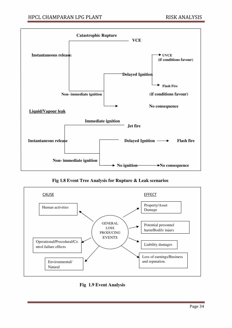
Fig 1.10 Release of flammable liquid
Fig 1.11 Vessel/pipe work rupture by external fire
Vessel rupture
Corrosion/Over
Pressure/
Overheat/Buckling
Pipe rupture/leak
by impact/Fire
Gasket/
Pump Seal leaks
MS
Overfill in Vapour
space also
Release of Flammable
liquid
Vessel/Pipe work rupture by external fire
Flowing/Burning liquid Heat Radiation rupture
Radiation capable of
causing rupture
Fire protection failure
Heat Radiation
High Heat
Radiation level
HPCL CHAMPARAN LPG PLANT RISK ANALYSIS
Page 36
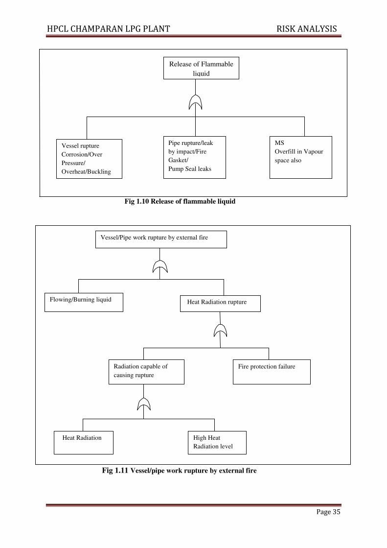
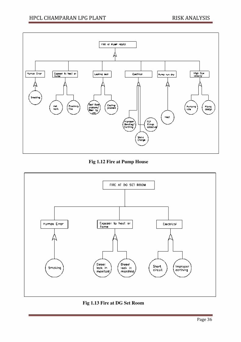
Fig 1.12 Fire at Pump House
Fig 1.13 Fire at DG Set Room
HPCL CHAMPARAN LPG PLANT RISK ANALYSIS
Page 37
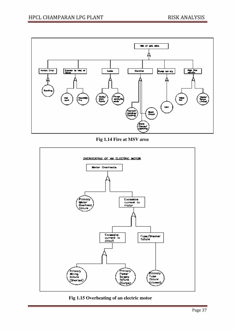
Fig 1.14 Fire at MSV area
Fig 1.15 Overheating of an electric motor
HPCL CHAMPARAN LPG PLANT RISK ANALYSIS
Page 38
Lighting
Static
External
Fire
Hot
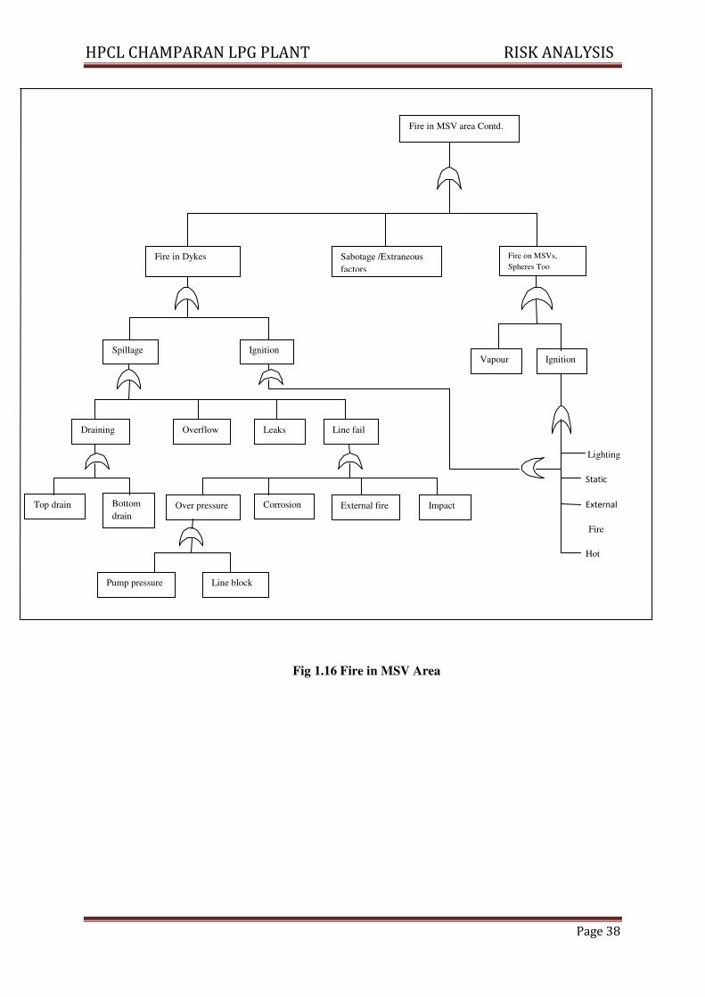
Fig 1.16 Fire in MSV Area
Fire in MSV area Contd.
Fire in Dykes Sabotage /Extraneous
factors
Fire on MSVs,
Spheres Too
Spillage Ignition
Leaks Overflow Draining Line fail
Vapour Ignition
Top drain Bottom
drain Over pressure Corrosion External fire Impact
Pump pressure Line block
HPCL CHAMPARAN LPG PLANT RISK ANALYSIS
Page 39
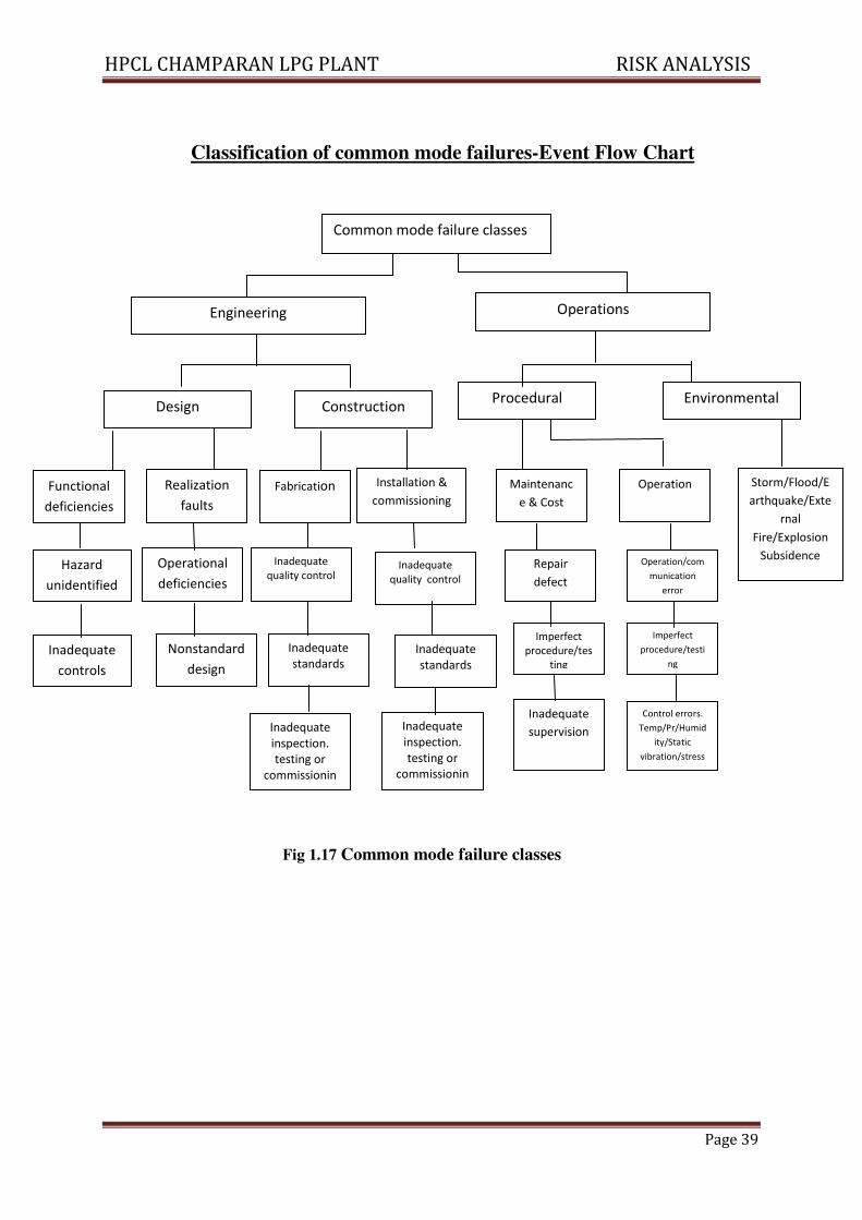
Classification of common mode failures-Event Flow Chart
Fig 1.17 Common mode failure classes
Engineering Operations
Design Construction
Realization
faults
Functional
deficiencies
Installation &
commissioning Fabrication
Hazard
unidentified
Operational
deficiencies
Inadequate
quality control Inadequate
quality control
Environmental Procedural
Maintenanc
e & Cost
Operation Storm/Flood/E
arthquake/Exte
rnal
Fire/Explosion
Subsidence Repair
defect
Operation/com
munication
error
Imperfect
procedure/tes
ting
Imperfect
procedure/testi
ng
Inadequate
inspection.
testing or
commissionin
g
Inadequate
inspection.
testing or
commissionin
g
Inadequate
supervision
Control errors.
Temp/Pr/Humid
ity/Static
vibration/stress
Inadequate
controls
Nonstandard
design
Inadequate
standards Inadequate
standards
Common mode failure classes
HPCL CHAMPARAN LPG PLANT RISK ANALYSIS
Page 40
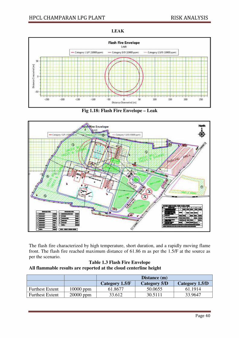
Fig 1.18: Flash Fire Envelope – Leak
The flash fire characterized by high temperature, short duration, and a rapidly moving flame
front. The flash fire reached maximum distance of 61.86 m as per the 1.5/F at the source as
per the scenario.
Table 1.3 Flash Fire Envelope
All flammable results are reported at the cloud centerline height
Distance (m)
Category 1.5/F Category 5/D Category 1.5/D
Furthest Extent 10000 ppm 61.8677 50.0655 61.1914
Furthest Extent 20000 ppm 33.612 30.5111 33.9647
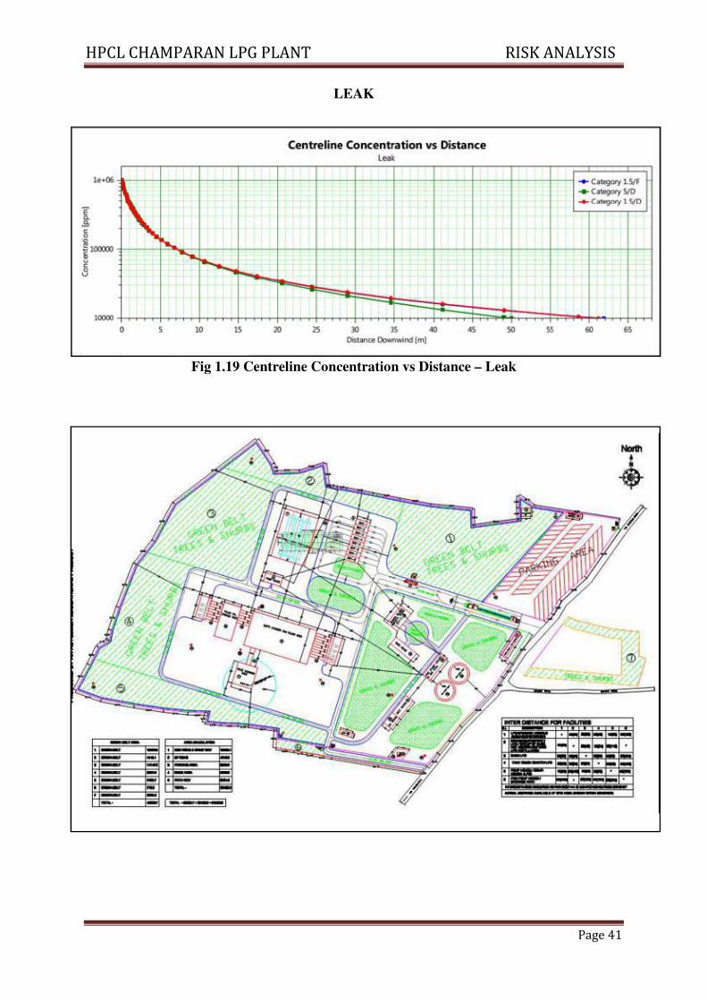
LEAK
HPCL CHAMPARAN LPG PLANT RISK ANALYSIS
Page 41
LEAK
Fig 1.19 Centreline Concentration vs Distance – Leak
HPCL CHAMPARAN LPG PLANT RISK ANALYSIS
Page 42
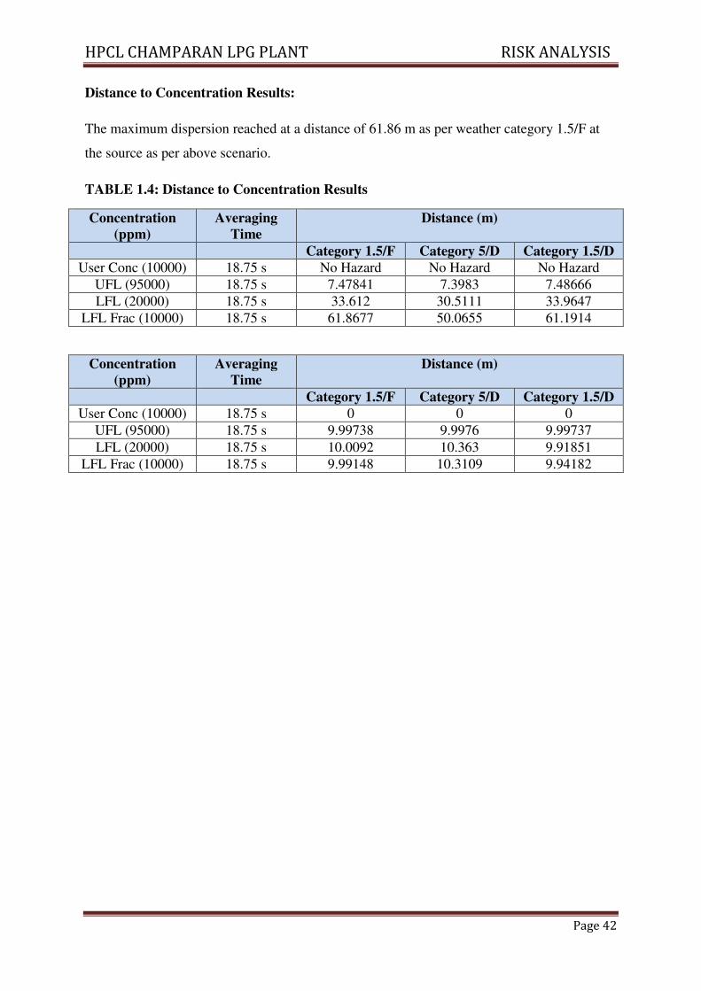
Distance to Concentration Results:
The maximum dispersion reached at a distance of 61.86 m as per weather category 1.5/F at
the source as per above scenario.
TABLE 1.4: Distance to Concentration Results
Concentration
(ppm)
Averaging
Time
Distance (m)
Category 1.5/F Category 5/D Category 1.5/D
User Conc (10000) 18.75 s No Hazard No Hazard No Hazard
UFL (95000) 18.75 s 7.47841 7.3983 7.48666
LFL (20000) 18.75 s 33.612 30.5111 33.9647
LFL Frac (10000) 18.75 s 61.8677 50.0655 61.1914
Concentration
(ppm)
Averaging
Time
Distance (m)
Category 1.5/F Category 5/D Category 1.5/D
User Conc (10000) 18.75 s 0 0 0
UFL (95000) 18.75 s 9.99738 9.9976 9.99737
LFL (20000) 18.75 s 10.0092 10.363 9.91851
LFL Frac (10000) 18.75 s 9.99148 10.3109 9.94182
HPCL CHAMPARAN LPG PLANT RISK ANALYSIS
Page 43
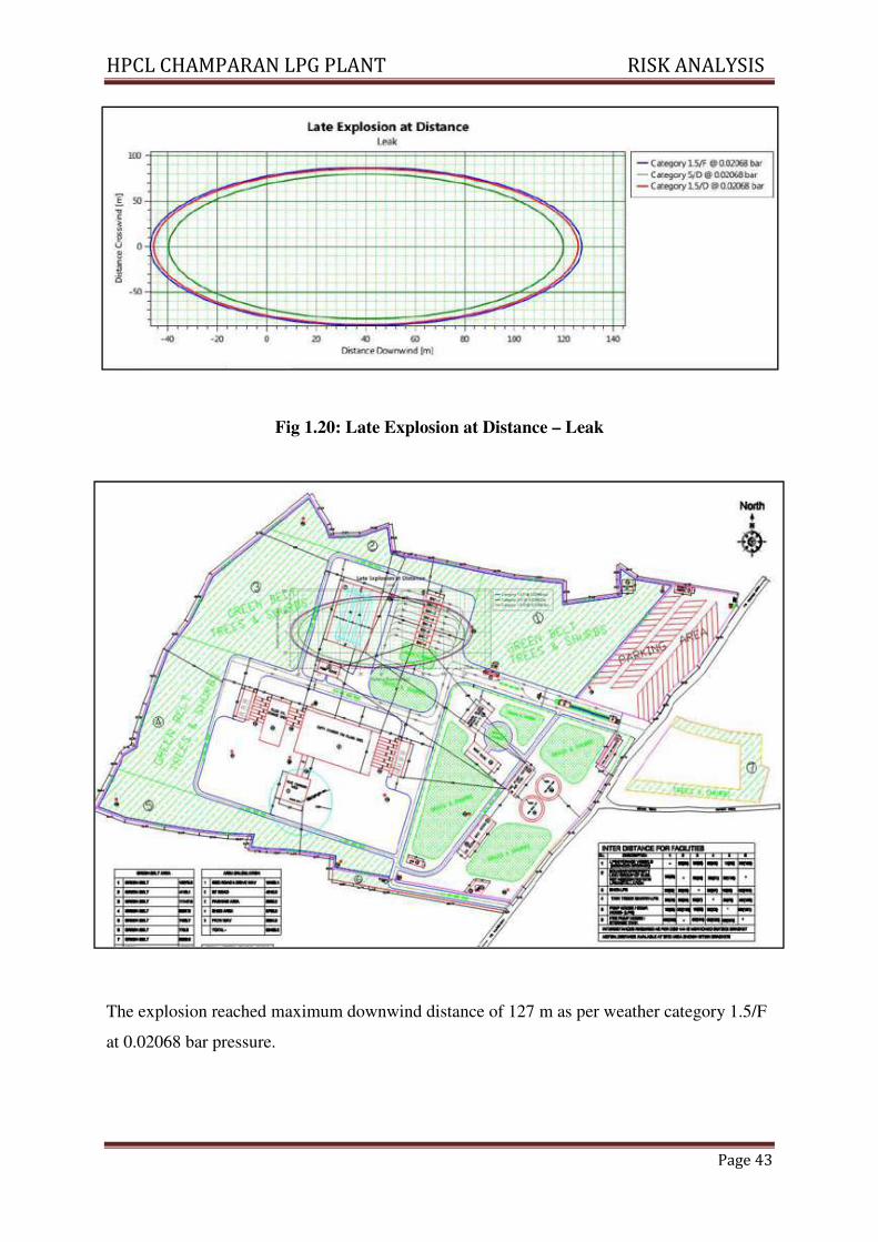
Fig 1.20: Late Explosion at Distance – Leak
The explosion reached maximum downwind distance of 127 m as per weather category 1.5/F
at 0.02068 bar pressure.
HPCL CHAMPARAN LPG PLANT RISK ANALYSIS
Page 44
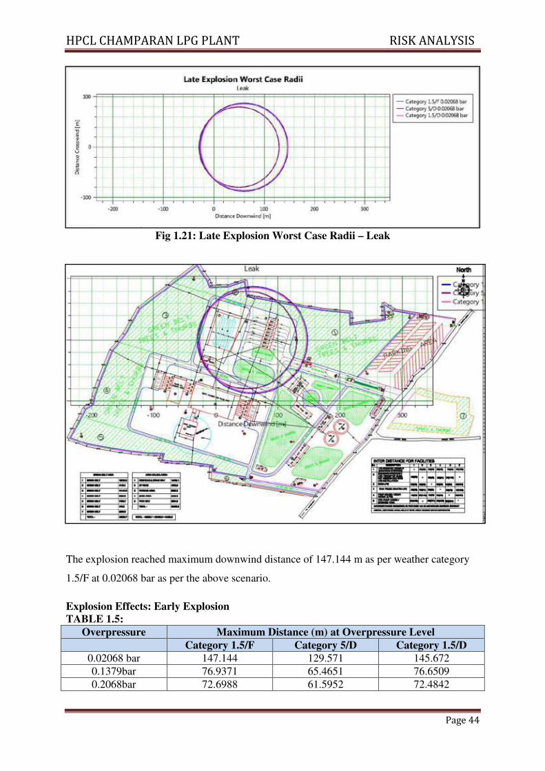
Fig 1.21: Late Explosion Worst Case Radii – Leak
The explosion reached maximum downwind distance of 147.144 m as per weather category
1.5/F at 0.02068 bar as per the above scenario.
Explosion Effects: Early Explosion
TABLE 1.5:
Overpressure Maximum Distance (m) at Overpressure Level
Category 1.5/F Category 5/D Category 1.5/D
0.02068 bar 147.144 129.571 145.672
0.1379bar 76.9371 65.4651 76.6509
0.2068bar 72.6988 61.5952 72.4842
HPCL CHAMPARAN LPG PLANT RISK ANALYSIS
Page 45
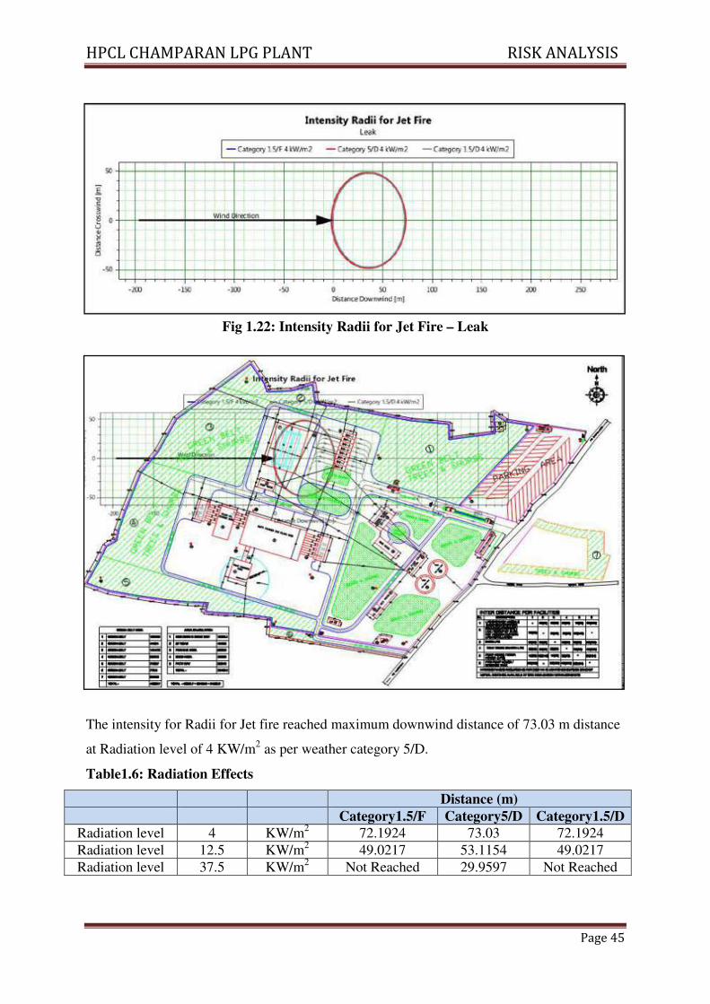
Fig 1.22: Intensity Radii for Jet Fire – Leak
The intensity for Radii for Jet fire reached maximum downwind distance of 73.03 m distance
at Radiation level of 4 KW/m2 as per weather category 5/D.
Table1.6: Radiation Effects
Distance (m)
Category1.5/F Category5/D Category1.5/D
Radiation level 4 KW/m2 72.1924 73.03 72.1924
Radiation level 12.5 KW/m2 49.0217 53.1154 49.0217
Radiation level 37.5 KW/m2 Not Reached 29.9597 Not Reached
HPCL CHAMPARAN LPG PLANT RISK ANALYSIS
Page 46
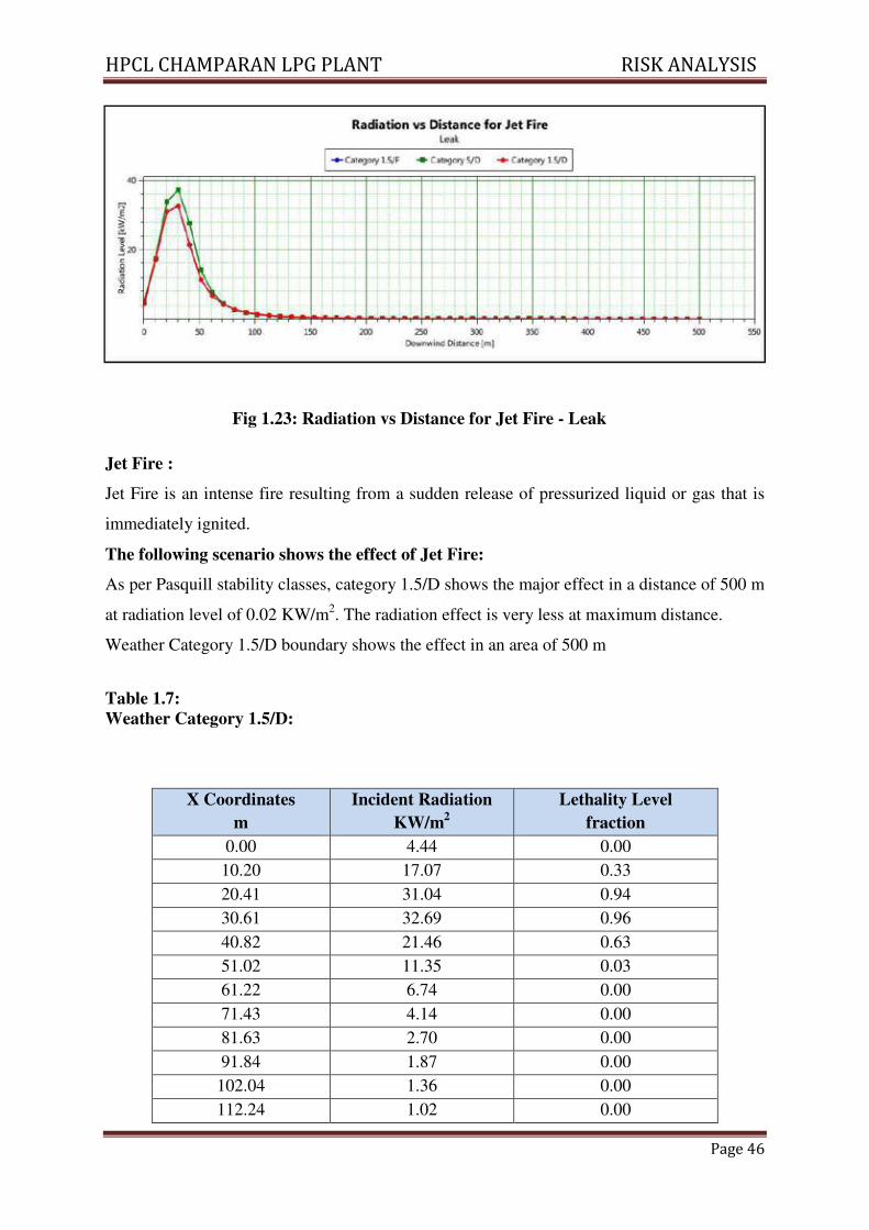
Fig 1.23: Radiation vs Distance for Jet Fire - Leak
Jet Fire :
Jet Fire is an intense fire resulting from a sudden release of pressurized liquid or gas that is
immediately ignited.
The following scenario shows the effect of Jet Fire:
As per Pasquill stability classes, category 1.5/D shows the major effect in a distance of 500 m
at radiation level of 0.02 KW/m2. The radiation effect is very less at maximum distance.
Weather Category 1.5/D boundary shows the effect in an area of 500 m
Table 1.7:
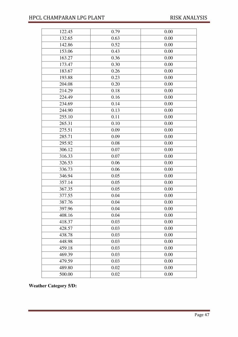
Weather Category 1.5/D:
X Coordinates
m
Incident Radiation
KW/m2
Lethality Level
fraction
0.00 4.44 0.00
10.20 17.07 0.33
20.41 31.04 0.94
30.61 32.69 0.96
40.82 21.46 0.63
51.02 11.35 0.03
61.22 6.74 0.00
71.43 4.14 0.00
81.63 2.70 0.00
91.84 1.87 0.00
102.04 1.36 0.00
112.24 1.02 0.00
HPCL CHAMPARAN LPG PLANT RISK ANALYSIS
Page 47
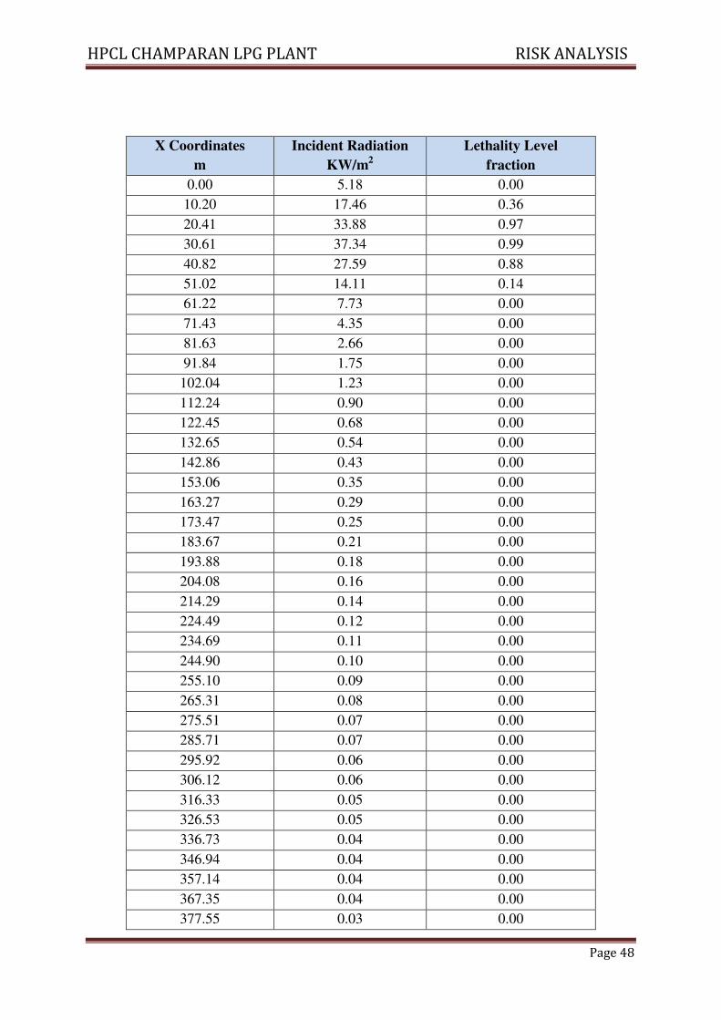
Weather Category 5/D:
122.45 0.79 0.00
132.65 0.63 0.00
142.86 0.52 0.00
153.06 0.43 0.00
163.27 0.36 0.00
173.47 0.30 0.00
183.67 0.26 0.00
193.88 0.23 0.00
204.08 0.20 0.00
214.29 0.18 0.00
224.49 0.16 0.00
234.69 0.14 0.00
244.90 0.13 0.00
255.10 0.11 0.00
265.31 0.10 0.00
275.51 0.09 0.00
285.71 0.09 0.00
295.92 0.08 0.00
306.12 0.07 0.00
316.33 0.07 0.00
326.53 0.06 0.00
336.73 0.06 0.00
346.94 0.05 0.00
357.14 0.05 0.00
367.35 0.05 0.00
377.55 0.04 0.00
387.76 0.04 0.00
397.96 0.04 0.00
408.16 0.04 0.00
418.37 0.03 0.00
428.57 0.03 0.00
438.78 0.03 0.00
448.98 0.03 0.00
459.18 0.03 0.00
469.39 0.03 0.00
479.59 0.03 0.00
489.80 0.02 0.00
500.00 0.02 0.00
HPCL CHAMPARAN LPG PLANT RISK ANALYSIS
Page 48
X Coordinates
m
Incident Radiation
KW/m2
Lethality Level
fraction
0.00 5.18 0.00
10.20 17.46 0.36
20.41 33.88 0.97
30.61 37.34 0.99
40.82 27.59 0.88
51.02 14.11 0.14
61.22 7.73 0.00
71.43 4.35 0.00
81.63 2.66 0.00
91.84 1.75 0.00
102.04 1.23 0.00
112.24 0.90 0.00
122.45 0.68 0.00
132.65 0.54 0.00
142.86 0.43 0.00
153.06 0.35 0.00
163.27 0.29 0.00
173.47 0.25 0.00
183.67 0.21 0.00
193.88 0.18 0.00
204.08 0.16 0.00
214.29 0.14 0.00
224.49 0.12 0.00
234.69 0.11 0.00
244.90 0.10 0.00
255.10 0.09 0.00
265.31 0.08 0.00
275.51 0.07 0.00
285.71 0.07 0.00
295.92 0.06 0.00
306.12 0.06 0.00
316.33 0.05 0.00
326.53 0.05 0.00
336.73 0.04 0.00
346.94 0.04 0.00
357.14 0.04 0.00
367.35 0.04 0.00
377.55 0.03 0.00
HPCL CHAMPARAN LPG PLANT RISK ANALYSIS
Page 49
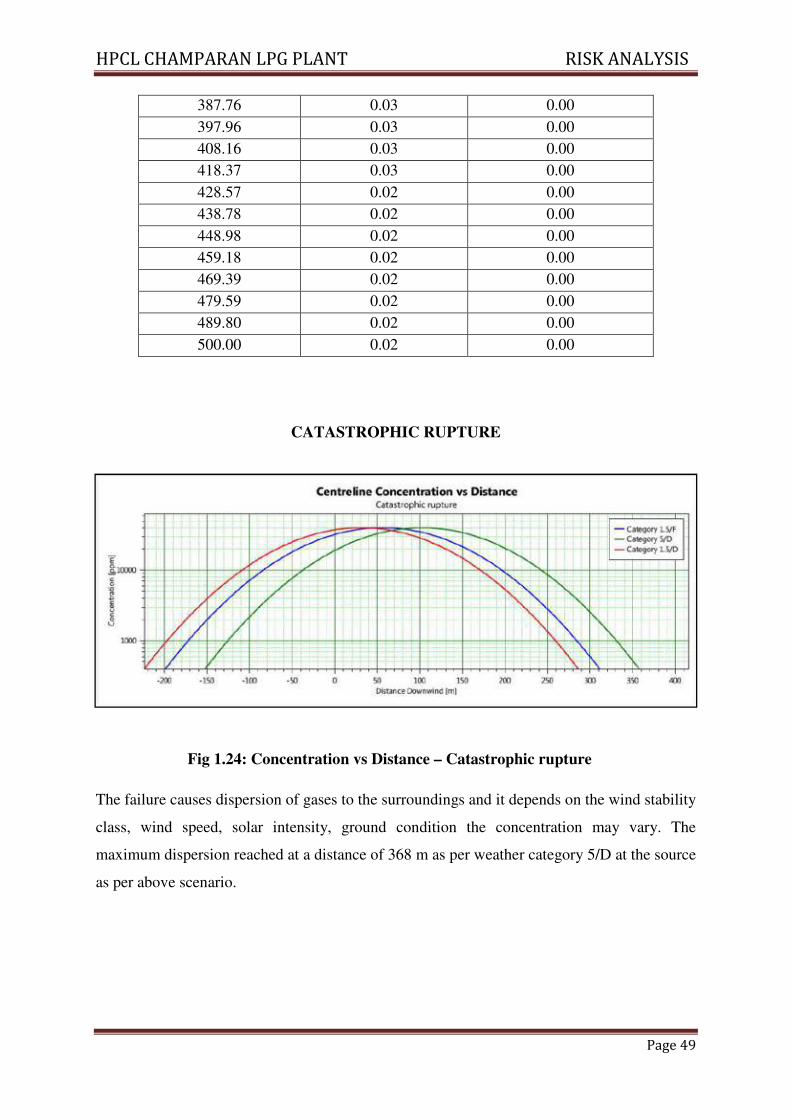
CATASTROPHIC RUPTURE
Fig 1.24: Concentration vs Distance – Catastrophic rupture
The failure causes dispersion of gases to the surroundings and it depends on the wind stability
class, wind speed, solar intensity, ground condition the concentration may vary. The
maximum dispersion reached at a distance of 368 m as per weather category 5/D at the source
as per above scenario.
387.76 0.03 0.00
397.96 0.03 0.00
408.16 0.03 0.00
418.37 0.03 0.00
428.57 0.02 0.00
438.78 0.02 0.00
448.98 0.02 0.00
459.18 0.02 0.00
469.39 0.02 0.00
479.59 0.02 0.00
489.80 0.02 0.00
500.00 0.02 0.00
HPCL CHAMPARAN LPG PLANT RISK ANALYSIS
Page 50
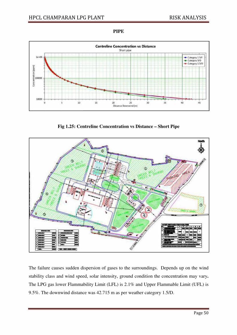
PIPE
Fig 1.25: Centreline Concentration vs Distance – Short Pipe
The failure causes sudden dispersion of gases to the surroundings. Depends up on the wind
stability class and wind speed, solar intensity, ground condition the concentration may vary.
The LPG gas lower Flammability Limit (LFL) is 2.1% and Upper Flammable Limit (UFL) is
9.5%. The downwind distance was 42.715 m as per weather category 1.5/D.
HPCL CHAMPARAN LPG PLANT RISK ANALYSIS
Page 51
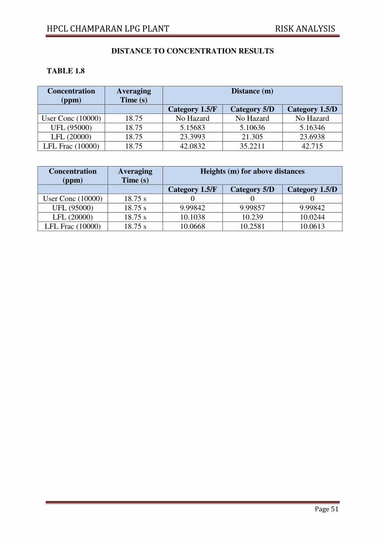
DISTANCE TO CONCENTRATION RESULTS
TABLE 1.8
Concentration
(ppm)
Averaging
Time (s)
Distance (m)
Category 1.5/F Category 5/D Category 1.5/D
User Conc (10000) 18.75 No Hazard No Hazard No Hazard
UFL (95000) 18.75 5.15683 5.10636 5.16346
LFL (20000) 18.75 23.3993 21.305 23.6938
LFL Frac (10000) 18.75 42.0832 35.2211 42.715
Concentration
(ppm)
Averaging
Time (s)
Heights (m) for above distances
Category 1.5/F Category 5/D Category 1.5/D
User Conc (10000) 18.75 s 0 0 0
UFL (95000) 18.75 s 9.99842 9.99857 9.99842
LFL (20000) 18.75 s 10.1038 10.239 10.0244
LFL Frac (10000) 18.75 s 10.0668 10.2581 10.0613
HPCL CHAMPARAN LPG PLANT RISK ANALYSIS
Page 52
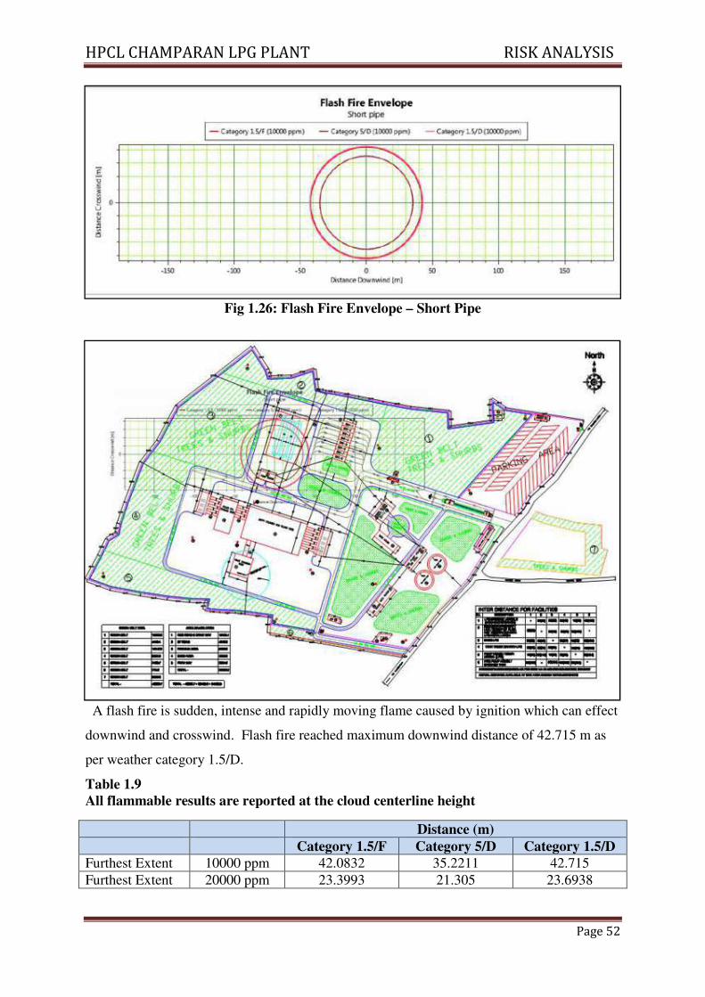
Fig 1.26: Flash Fire Envelope – Short Pipe
A flash fire is sudden, intense and rapidly moving flame caused by ignition which can effect
downwind and crosswind. Flash fire reached maximum downwind distance of 42.715 m as
per weather category 1.5/D.
Table 1.9
All flammable results are reported at the cloud centerline height
Distance (m)
Category 1.5/F Category 5/D Category 1.5/D
Furthest Extent 10000 ppm 42.0832 35.2211 42.715
Furthest Extent 20000 ppm 23.3993 21.305 23.6938
HPCL CHAMPARAN LPG PLANT RISK ANALYSIS
Page 53
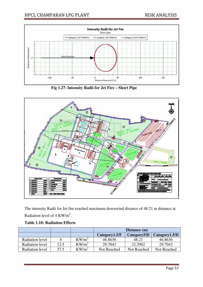
Fig 1.27: Intensity Radii for Jet Fire – Short Pipe
The intensity Radii for Jet fire reached maximum downwind distance of 48.21 m distance at
Radiation level of 4 KW/m2.
Table 1.10: Radiation Effects
Distance (m)
Category1.5/F Category5/D Category1.5/D
Radiation level 4 KW/m2 46.8636 48.21 46.8636
Radiation level 12.5 KW/m2 29.7043 32.2902 29.7043
Radiation level 37.5 KW/m2 Not Reached Not Reached Not Reached
HPCL CHAMPARAN LPG PLANT RISK ANALYSIS
Page 54
1.21 FIRE PROTECTION AND FIRE FIGHTING SYSTEM
The plant will be equipped with a comprehensive fire protection system. Following
facilities will be provided for the fire protection:-
• Fire Water Supply
• Fire Hydrant system, Fire sprinkler system with smoke/fire detectors
• Portable Fire Extinguishers
1.21.1 Fire Fighting Facilities:
� 2 x 3500 KL Fire water storage tanks – water storage for handling 4hrs of fire fighting
to extinguish one major fire
� 5 Nos. x 410 Kl/hr Fire pumps ( 3 nos. working + 2 nos. standby) in Auto running
mode
� Pressurized (at 7 kg/sqcm at farthest end of fire network) Fire hydrant network around
all LPG facilities with series of Hydrant valves and Monitors @ 30m interval
� Fully automatic Sprinkler system activated by Quartzoid bulbs and Break glass for all
LPG Facilities
� Approx. nos. of Fire Monitors- 40; DH Hydrants – 50
1.21.2 Safety & Security Features in the Proposed Plant:
• Gas monitoring system (with visual & alarm indications) with approx. 30-35 Sensors
at all critical areas in the plant.
• Fire Extinguishers
• DCP 10 kgs – 70-80 nos.
• DCP 75 Kgs – 4 nos.
• CO2 – 8-10 nos.
• Paging and Announcing System for faster & safe communication
• VHF communication system for two way communication
• Personal Protective Equipment – Fire Entry suit, Water Gel blanket, Low temp suit /
gloves, First aid, special tools, helmets, etc.
• CCTV for the Incoming and outgoing vehicles and movement of personal in the
premises and along the boundary line
• Biometric access for the visitors entry Control room Monitoring
HPCL CHAMPARAN LPG PLANT RISK ANALYSIS
Page 55
1.22 MITIGATION MEASURES:
Measures and recommendations for the proposed Tank Farm area are as follows:-
• Adherence of international engineering standards in the Design, Construction and testing
• All tanks to be provided with automatic sprinkler system interlinked with fusible bulbs, the
sprinkler system to confirm to TAC design guidelines.
• All storage tanks to have level indicators wherever required.
• All pumps used to have mechanical seal to prevent leakages and fugitive emission.
• Storage areas shall be free from accumulation of materials.
• There should be good communication system available near tank farm area to the control
room.
• The LPG storage shall be located in upwind direction from any flammable source.
• A good layout should provide for adequate fire fighting access, means of escape in case of
fire and also segregation of facilities so that adjacent facilities are not endangered during a
fire.
• All flame proof motors in hazardous area should be provided with double earthing.
• All electric fittings used in the LPG pump house & storage area should be flame proof type.
• A telephone should be provided which is freely available and readily accessible for the
reporting of accidents or emergency situations. The emergency telephone numbers should
include the fire department, ambulance service, emergency response team, hospital and
police.
1. LPG leakage should be stopped immediately when noticed.
2. LPG sensors play a very important role therefore sensors should be tested at
regular intervals.
3. Record of LPG sensors should be maintained indicating the date & time of alarm,
Location of Sensors, Details of Leakage and action taken.
Wind Direction Indicator:
4. Windsock should immediately be replaced whenever found in torn condition. It
must be ensured that the indicator is visible from all places in the plant. It should
be ensured that the Wind sock is visible during night time also.
Weeds, grass, shrubs:
5. Weeds, grass, shrubs or any combustible material should be removed from the
plant premises.
HPCL CHAMPARAN LPG PLANT RISK ANALYSIS
Page 56
For Safe Operational Practices:
6. All Fire Extinguishers should be properly placed according to OISD norm. After
expiry date of Fire Extinguisher It should be replace soon.
Emergency Plan:
7. Mock Drill involving District Emergency services (Fire Brigade, Hospitals, Police,
District Collector ate etc.) should be carried out minimum once in a year.
1.23 CONCLUSION:
The latest version of the renowned PHAST Lite software package of DNV is used for carrying
out the risk analysis.
Following are some of these references adopted for the study:
• Guide to Manufacture, Storage and Import of Hazardous Chemicals Rules (MSIHC), 1989
issued by the Ministry of Environment and Forests (MoEF), Govt. of India as amended up
to date.
• World Bank Technical papers relating to “Techniques for assessing Industrial Hazards”.
• “Major Hazard Control” by ILO.
• Risk Management Program guidelines by EPA (US).
The scenario (Catastrophic rupture) is based on large-scale release of material stored in the
tank and the use of worst stability class, though this may not always happen. We have assumed
catastrophic rupture for all the tanks as per the guidelines suggested by DNV – UK. Similarly,
maximum inventory in the tank at the time of failure is assumed.
HPCL CHAMPARAN LPG PLANT RISK ANALYSIS
Page 57
2.0 VISUALIZATION OF MCA SCENARIOS
2.1. Introduction
A Maximum Credible Accident (MCA) can be characterized, as an accident with a
maximum damage potential, which is believed to be credible. For selection of a MCA
scenario following factors have been taken into account.
1. Flammable and explosive nature of LPG
2. Quantity of material present in a unit or involved in an activity
3. Process or storage conditions such as temperature, pressure, flow, mixing and
presence of incompatible materials
2.1.1 Chemical Inventory Analysis
Maximum inventory of LPG in storage vessels, road tanker and LPG cylinders has
been considered.
2.1.2 Identification of Chemical Release & Accident Scenarios
The accident scenarios have been divided into the following categories according to
the mode of release of LPG, physical effects and the resulting damages:
(a) Pressurized liquefied gas or boiling liquid releases under pressure leading to
fireball.
(b) Flammable gas release leading to Vapor Cloud Explosion (VCE)
(c) Jet fire of spillage mainly causing different levels of incident thermal radiation
(d) Spreading of hydrocarbon vapour with wind posing fire hazard to the surrounding
property and population depending upon level of concentration
2.2 PERTINENT PAST ACCIDENT DATA/CASE HISTORY ANALYSIS
2.2.1 Industrial Disasters
Analysis of past accidents provides a wealth of information and valuable clues in
support of possible modes of occurrence of hazards along with their effects and
consequences. Extensive coverage of past accident information could be obtained
from established computerized data banks and literature databases.
Bhopal gas leakage incident, series of explosions involving LPG in Mexico City
resulted in 650 deaths and several thousand injuries. An explosion involving propane
gas leads to 51 fatalities and many injuries in Ortuella Spain in 1980. Flixborough
accident killed 28 and injured 89 persons due to cyclohexane explosion in 1974.
HPCL CHAMPARAN LPG PLANT RISK ANALYSIS
Page 58
In all these cases the cause has been found to be different but the fact remains that
storage, handling or processing of flammable, explosive or toxic chemicals has
potential to cause massive loss of human life, property and environment. The damage
potential, therefore, is a function of both, the inherent nature of the chemical and the
quantity that is present on the site.
2.2.2 Types & Consequences of Previous Fire & Explosion
Massive disaster usually occurs on loss of flammable or explosive material from
containment, for example:
∗ Leakage of flammable chemical, mixing of the chemical with air, formation of a
flammable vapor cloud and drifting of the cloud to a source of ignition leading to
a fire or an explosion affecting the site and possibly populated areas nearby
“Back fire” phenomenon has been observed in most of the cases of fire and explosion.
Majority of the accidents involving LPG started with comparatively smaller leakage
leading to formation of a plume. The gas then drifted in the down wind direction and
came in contact with an ignition source. Thus resulting in a vapor cloud explosion.
Fire due to the VCE traveled back to the source of leakage and escalated the damage
with occurrence of a fireball. Because of the fireball, similar storage in the
surrounding area were severely affected either due to heat intensity of the fire ball or
due to mechanical damage because of pressure waves of the explosion or flying
fragments of the storage vessel. Therefore resulting into another fireball and thus the
escalation of fire and explosion continued destroying the complete plant.
Intensities of fire, explosion and pressure waves have been found significantly
dependent on many variable factors such as availability of ignition source, wind
direction and speed, atmospheric stability, time of accident and weather conditions.
The effects of fire on people may be in anything from skin burns to deaths due to
exposure to thermal radiation. The severity of the burns would further depend on the
intensity of the heat and the exposure time. Heat radiation is inversely proportional to
the square of the distance from the source.
Fires occur in industry more frequently than explosions. Fires can take several
different forms, including jet fires, vapour cloud explosions, flash fires.
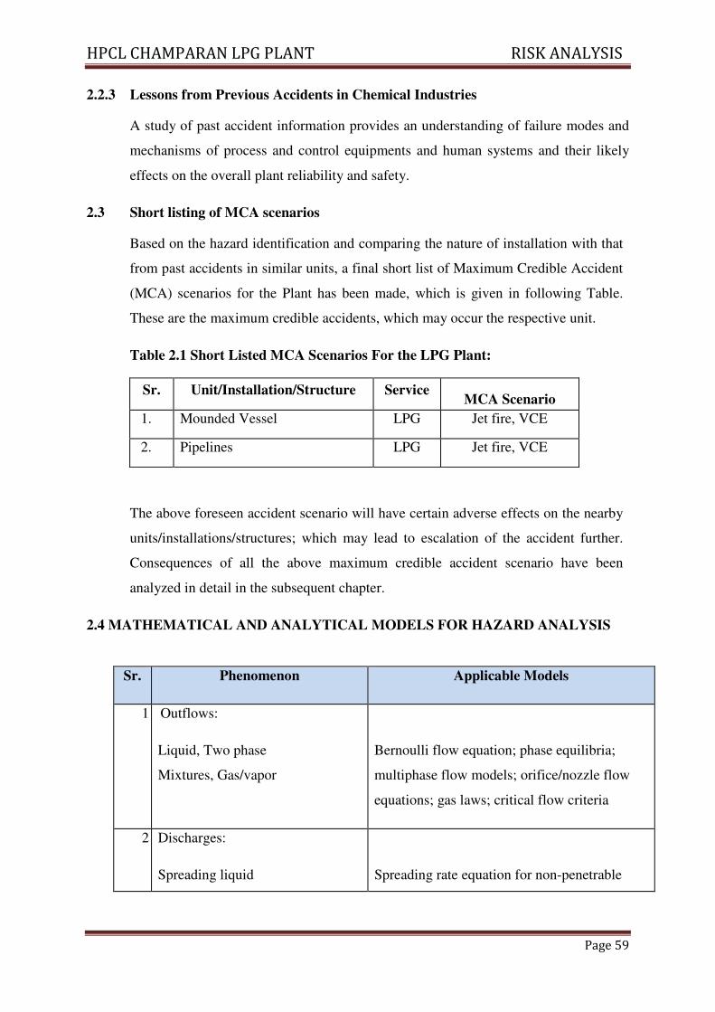
HPCL CHAMPARAN LPG PLANT RISK ANALYSIS
Page 59
2.2.3 Lessons from Previous Accidents in Chemical Industries
A study of past accident information provides an understanding of failure modes and
mechanisms of process and control equipments and human systems and their likely
effects on the overall plant reliability and safety.
2.3 Short listing of MCA scenarios
Based on the hazard identification and comparing the nature of installation with that
from past accidents in similar units, a final short list of Maximum Credible Accident
(MCA) scenarios for the Plant has been made, which is given in following Table.
These are the maximum credible accidents, which may occur the respective unit.
Table 2.1 Short Listed MCA Scenarios For the LPG Plant:
Sr. Unit/Installation/Structure Service MCA Scenario
1. Mounded Vessel LPG Jet fire, VCE
2. Pipelines LPG Jet fire, VCE
The above foreseen accident scenario will have certain adverse effects on the nearby
units/installations/structures; which may lead to escalation of the accident further.
Consequences of all the above maximum credible accident scenario have been
analyzed in detail in the subsequent chapter.
2.4 MATHEMATICAL AND ANALYTICAL MODELS FOR HAZARD ANALYSIS
Sr. Phenomenon Applicable Models
1 Ou Outflows:
Liquid, Two phase
Mixtures, Gas/vapor
Bernoulli flow equation; phase equilibria;
multiphase flow models; orifice/nozzle flow
equations; gas laws; critical flow criteria
2 DI Discharges:
Spreading liquid
Spreading rate equation for non-penetrable
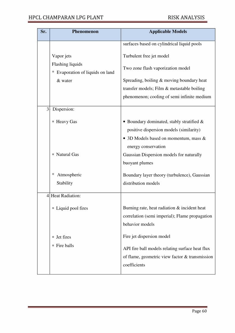
HPCL CHAMPARAN LPG PLANT RISK ANALYSIS
Page 60
Sr. Phenomenon Applicable Models
Vapor jets
Flashing liquids
* Evaporation of liquids on land
& water
surfaces based on cylindrical liquid pools
Turbulent free jet model
Two zone flash vaporization model
Spreading, boiling & moving boundary heat
transfer models; Film & metastable boiling
phenomenon; cooling of semi infinite medium
3 cvo Dispersion:
∗ Heavy Gas
∗ Natural Gas
* Atmospheric
Stability
• Boundary dominated, stably stratified &
positive dispersion models (similarity)
• 3D Models based on momentum, mass &
energy conservation
Gaussian Dispersion models for naturally
buoyant plumes
Boundary layer theory (turbulence), Gaussian
distribution models
4 Heat Radiation:
∗ Liquid pool fires
∗ Jet fires
∗ Fire balls
Burning rate, heat radiation & incident heat
correlation (semi imperial); Flame propagation
behavior models
Fire jet dispersion model
API fire ball models relating surface heat flux
of flame, geometric view factor & transmission
coefficients
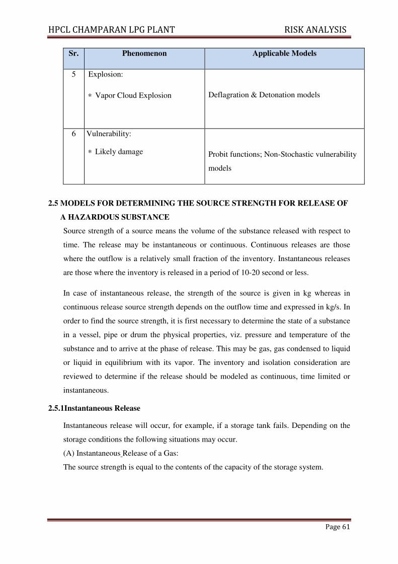
HPCL CHAMPARAN LPG PLANT RISK ANALYSIS
Page 61
Sr. Phenomenon Applicable Models
5 Explosion:
∗ Vapor Cloud Explosion
Deflagration & Detonation models
6 Vulnerability:
∗ Likely damage
Probit functions; Non-Stochastic vulnerability
models
2.5 MODELS FOR DETERMINING THE SOURCE STRENGTH FOR RELEASE OF
A HAZARDOUS SUBSTANCE
Source strength of a source means the volume of the substance released with respect to
time. The release may be instantaneous or continuous. Continuous releases are those
where the outflow is a relatively small fraction of the inventory. Instantaneous releases
are those where the inventory is released in a period of 10-20 second or less.
In case of instantaneous release, the strength of the source is given in kg whereas in
continuous release source strength depends on the outflow time and expressed in kg/s. In
order to find the source strength, it is first necessary to determine the state of a substance
in a vessel, pipe or drum the physical properties, viz. pressure and temperature of the
substance and to arrive at the phase of release. This may be gas, gas condensed to liquid
or liquid in equilibrium with its vapor. The inventory and isolation consideration are
reviewed to determine if the release should be modeled as continuous, time limited or
instantaneous.
2.5.1Instantaneous Release
Instantaneous release will occur, for example, if a storage tank fails. Depending on the
storage conditions the following situations may occur.
(A) Instantaneous Release of a Gas:
The source strength is equal to the contents of the capacity of the storage system.
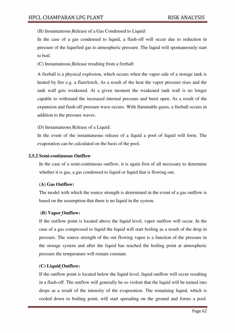
HPCL CHAMPARAN LPG PLANT RISK ANALYSIS
Page 62
(B) Instantaneous Release of a Gas Condensed to Liquid:
In the case of a gas condensed to liquid, a flash-off will occur due to reduction in
pressure of the liquefied gas to atmospheric pressure. The liquid will spontaneously start
to boil.
(C) Instantaneous Release resulting from a fireball:
A fireball is a physical explosion, which occurs when the vapor side of a storage tank is
heated by fire e.g. a flare/torch. As a result of the heat the vapor pressure rises and the
tank wall gets weakened. At a given moment the weakened tank wall is no longer
capable to withstand the increased internal pressure and burst open. As a result of the
expansion and flash-off pressure wave occurs. With flammable gases, a fireball occurs in
addition to the pressure waves.
(D) Instantaneous Release of a Liquid:
In the event of the instantaneous release of a liquid a pool of liquid will form. The
evaporation can be calculated on the basis of the pool.
2.5.2 Semi-continuous Outflow
In the case of a semi-continuous outflow, it is again first of all necessary to determine
whether it is gas, a gas condensed to liquid or liquid that is flowing out.
(A) Gas Outflow:
The model with which the source strength is determined in the event of a gas outflow is
based on the assumption that there is no liquid in the system.
(B) Vapor Outflow:
If the outflow point is located above the liquid level, vapor outflow will occur. In the
case of a gas compressed to liquid the liquid will start boiling as a result of the drop in
pressure. The source strength of the out flowing vapor is a function of the pressure in
the storage system and after the liquid has reached the boiling point at atmospheric
pressure the temperature will remain constant.
(C) Liquid Outflow:
If the outflow point is located below the liquid level, liquid outflow will occur resulting
in a flash-off. The outflow will generally be so violent that the liquid will be turned into
drops as a result of the intensity of the evaporation. The remaining liquid, which is
cooled down to boiling point, will start spreading on the ground and forms a pool.
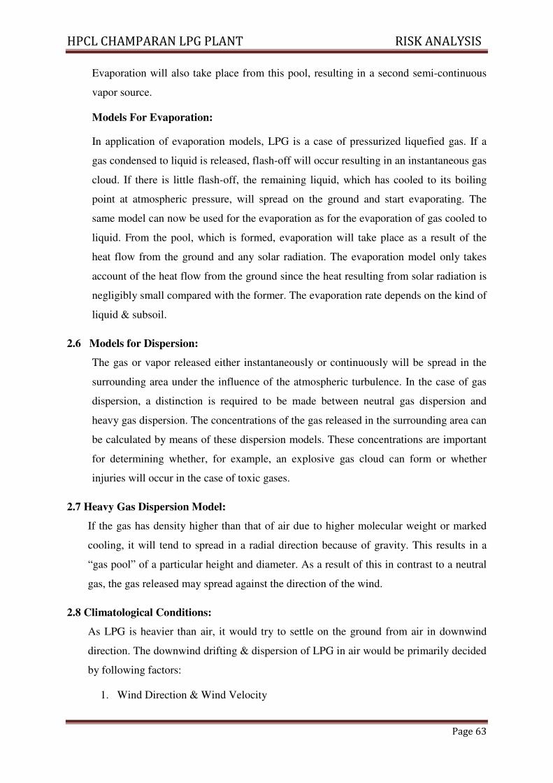
HPCL CHAMPARAN LPG PLANT RISK ANALYSIS
Page 63
Evaporation will also take place from this pool, resulting in a second semi-continuous
vapor source.
Models For Evaporation:
In application of evaporation models, LPG is a case of pressurized liquefied gas. If a
gas condensed to liquid is released, flash-off will occur resulting in an instantaneous gas
cloud. If there is little flash-off, the remaining liquid, which has cooled to its boiling
point at atmospheric pressure, will spread on the ground and start evaporating. The
same model can now be used for the evaporation as for the evaporation of gas cooled to
liquid. From the pool, which is formed, evaporation will take place as a result of the
heat flow from the ground and any solar radiation. The evaporation model only takes
account of the heat flow from the ground since the heat resulting from solar radiation is
negligibly small compared with the former. The evaporation rate depends on the kind of
liquid & subsoil.
2.6 Models for Dispersion:
The gas or vapor released either instantaneously or continuously will be spread in the
surrounding area under the influence of the atmospheric turbulence. In the case of gas
dispersion, a distinction is required to be made between neutral gas dispersion and
heavy gas dispersion. The concentrations of the gas released in the surrounding area can
be calculated by means of these dispersion models. These concentrations are important
for determining whether, for example, an explosive gas cloud can form or whether
injuries will occur in the case of toxic gases.
2.7 Heavy Gas Dispersion Model:
If the gas has density higher than that of air due to higher molecular weight or marked
cooling, it will tend to spread in a radial direction because of gravity. This results in a
“gas pool” of a particular height and diameter. As a result of this in contrast to a neutral
gas, the gas released may spread against the direction of the wind.
2.8 Climatological Conditions:
As LPG is heavier than air, it would try to settle on the ground from air in downwind
direction. The downwind drifting & dispersion of LPG in air would be primarily decided
by following factors:
1. Wind Direction & Wind Velocity
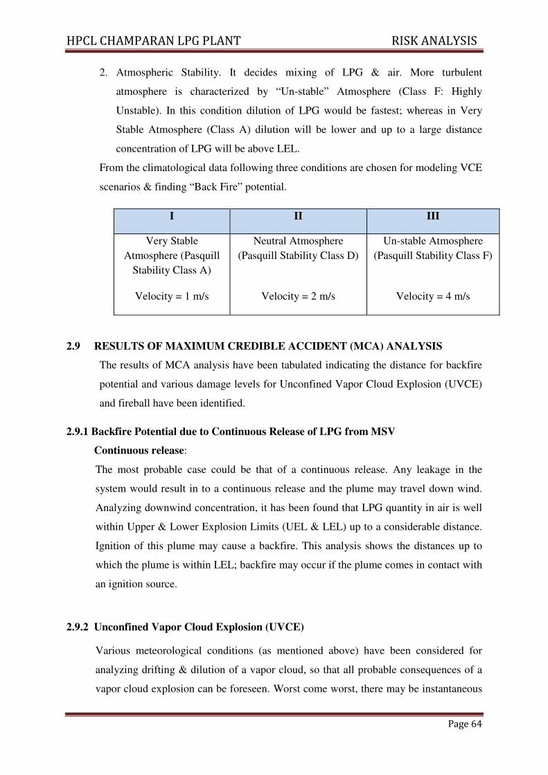
HPCL CHAMPARAN LPG PLANT RISK ANALYSIS
Page 64
2. Atmospheric Stability. It decides mixing of LPG & air. More turbulent
atmosphere is characterized by “Un-stable” Atmosphere (Class F: Highly
Unstable). In this condition dilution of LPG would be fastest; whereas in Very
Stable Atmosphere (Class A) dilution will be lower and up to a large distance
concentration of LPG will be above LEL.
From the climatological data following three conditions are chosen for modeling VCE
scenarios & finding “Back Fire” potential.
I II III
Very Stable
Atmosphere (Pasquill
Stability Class A)
Neutral Atmosphere
(Pasquill Stability Class D)
Un-stable Atmosphere
(Pasquill Stability Class F)
Velocity = 1 m/s Velocity = 2 m/s Velocity = 4 m/s
2.9 RESULTS OF MAXIMUM CREDIBLE ACCIDENT (MCA) ANALYSIS
The results of MCA analysis have been tabulated indicating the distance for backfire
potential and various damage levels for Unconfined Vapor Cloud Explosion (UVCE)
and fireball have been identified.
2.9.1 Backfire Potential due to Continuous Release of LPG from MSV
Continuous release:
The most probable case could be that of a continuous release. Any leakage in the
system would result in to a continuous release and the plume may travel down wind.
Analyzing downwind concentration, it has been found that LPG quantity in air is well
within Upper & Lower Explosion Limits (UEL & LEL) up to a considerable distance.
Ignition of this plume may cause a backfire. This analysis shows the distances up to
which the plume is within LEL; backfire may occur if the plume comes in contact with
an ignition source.
2.9.2 Unconfined Vapor Cloud Explosion (UVCE)
Various meteorological conditions (as mentioned above) have been considered for
analyzing drifting & dilution of a vapor cloud, so that all probable consequences of a
vapor cloud explosion can be foreseen. Worst come worst, there may be instantaneous
HPCL CHAMPARAN LPG PLANT RISK ANALYSIS
Page 65
release of the entire LPG vapor present in the unit. If it comes in to contact of an
ignition source during or immediately after the release or as in a case of backfire
resulting in jet fire, it may lead to a fireball.
Otherwise, the second MCA scenario is drifting & dilution of a vapor cloud along the
wind and then coming into contact of an ignition source (i.e., case of delayed ignition),
leading to a VCE. This scenario is particularly important to identify unforeseen
OFF-SITE emergencies. Two kinds of vapor release scenarios have been considered,
i.e. instantaneous and continuous.
2.9.2.1 Instantaneous Release:
As the vapor cloud drifts in the wind direction, it may explode depending on the
quantity of LPG present within flammability limits and availability of ignition source.
Applying the pertinent models, quantity of LPG within flammability limits for various
downwind distances have been calculated for above mentioned wind conditions.
The catastrophic failure of vessel is one of the major accidental scenarios whose
effect is felt beyond plant boundary. The prevailing wind direction at the time of
accident will decide LFL path. Over pressure remain largely unaffected by wind
direction. The distances shown are for rupture of vessel filled upto its maximum
capacity. The hazard distances indicated will be much lower if the MSVs of LPG
tanker contain fewer inventories at the time of accidents. LFL path indicates that all
persons coming within the distance will be fatally injured.
2.9.2.2 Mounded Storage :
Mounded storage of LPG i.e. creating a sand mound around the LPG storage vessels,
which are placed above the ground level, is now increasingly being considered by
HPCL as the best solution for protecting LPG vessels.
The mounded storage system provides the following advantages:
1. LPG stored in the form of mounded storage eliminates the possibility of fireball.
2. The cover of the mound protects the vessel from fire engulfment, radiation from a
fire in close proximity and acts of sabotage or vandalism. Water cooling systems
are not required.
3. The area of land required to locate a mounded system is minimal compared to
conventional storage.
HPCL CHAMPARAN LPG PLANT RISK ANALYSIS
Page 66
The mounded storage of LPG has proved to be safer compared to above ground
vessels as it provides intrinsically passive & safe environment.
In addition, the mounding material provides good protection against most of the
external influences like flying objects and pressure waves from explosions.
2.9.2.3. Consequences of the Identified Accident Scenarios: Summary
1. LPG leakage may lead to back fire; however it is less likely that the leaked gas
would find an ignition source within the plant.
2. Due to backfire a jet fire may be caused at the source of leakage. (i.e, traveling
back of the fire from source of ignition to the place of release/leakage of LPG.
3. Massive release of LPG (cloud) may lead to VCE at a place where it comes in
contact with an ignition source.
4. Pressure wave effect of VCE may collapse other structures in the plant.
However, considering the LPG alarms, fire hydrant points, water monitors,
automatic sprinkler system, fire extinguishers, process safety alarms provided in
the LPG terminal as per OISD norms, reduce the chances of escalation of fire or
explosion.
5. Likely number of people affected by the identified accident scenario will depend
on many factors (e.g. time, wind direction, atmospheric stability, availability of
ignition source etc.).
2.10 Domino Effects:
As the proposed 3x350 MT is mounded area and there will not be any formulation of
BLEVE and each bullet isolated with inert material and tight packing. Hence the
domino effect in bullet not envisaged. Auto sprinklers and temperature recording
sensors provided in order to mitigate any fire and the system totally eliminate domino
effect.
HPCL CHAMPARAN LPG PLANT RISK ANALYSIS
Page 67
3.0 QRA RECOMMENDATIONS
S.No. Recommendations
1. Do’s and Don’ts to be displayed at all places in pictorial form.
2. The route plant should be prepared in such a way that in construction of new
loading bay should not hamper.
3. Offsite mock drill have to be conducted in consultation with district authorities and
Directorate of Industrial Safety and Health.
4. Effectiveness of the Fire and Explosion mitigation measures shall be periodically
measured recorded and reviewed.
5. Necessary first aid measures to be adopted and followed for the persons who
affected during fire/explosion emergency situations as a life saving measure in the
site itself.
6. LPG tanker loading Shed Slope shall be maintained in such a way that LPG Liquid
causing Unconfined vapour cloud Explosion will be drained outside the periphery
of the Trucks.
7. Vapor line to the mounded storages requires proper rigid support.
8. Separate escape route to be provided
9. Extra parking space to be provided to cater upcoming facility.
10. Wind speed and wind direction in digital mode to be provided for online
assessment.
11. Emergency contact numbers to be displayed at mounded storage area.
HPCL CHAMPARAN LPG PLANT RISK ANALYSIS
Page 68
Material Safety Data Sheet (MSDS) For LPG
A. Identification
CAS No. : 68476-85-7
Formula : C3H8 / C3H6 / C4H10 / C4H8
Description : Colorless, noncorrosive, odorless gas when pure. A foul-
smelling odourant is usually added.
B. Physical Properties
Molecular Weight : 22 to 58
Vapor Pressure : > 1 atm
Flammability Limits : Lower (LEL) = 2.1%;
Upper (UEL) = 9.5%
Category : 1 A Flammable (Osha Classification)
Reactivity : Reacts with strong oxidizers, Chlorine Dioxide
C. Fire/Explosion Hazards
Fire Hazards : Highly dangerous when exposed to heat, can react with
oxidizing material.
Explosion Hazards : Moderate when exposed to heat or flame
Fire Fighting : Carbon Dioxide, Dry Chemical Powder, Water
Sprays/Fog can be used.
Target Organs : Respiratory Systems CNS
Pathway : Inhalation
Symptoms : Lightheadedness, drowsiness, irritation in eyes, nose,
Skin, dermatitis, cold burn
HPCL CHAMPARAN LPG PLANT RISK ANALYSIS
Page 69
D. First Aid
Eye - If this chemical contacts the eyes, immediately wash the eyes with large amount of
water, occasionally lifting lower and upper lids. Get medical attention
immediately. Contact lenses should not be worn when working with this chemical.
Skin - If this chemical contacts the skin, promptly wash the contaminated skin with soap
and water. If this chemical penetrates the clothing, promptly remove the clothing
and wash the skin with soap and water. Get medical attention promptly.
Breath - If a person breathes large amounts of this chemical, move the exposed person to
fresh air at once. If breathing has stopped, perform mouth- to –mouth resuscitation.
Keep the affected person warm and at rest. Get medical attention as soon as
possible.
Recommended