Embed Size (px)
Citation preview
HINDUSTAN PETROLEUM CORPORATION LTD.
GANTRY AND ALLIED JOBS AT AJMER & JAIPUR Page 1 of 275
HINDUSTAN PETROLEUM CORPORATION LIMITED,
E & P DEPTT, 2nd FLOOR, Gresham assurance bldg, Sir P.M.Road, Fort,
MUMBAI-1
TENDER DOCUMENT
FOR
CONSTRUCTION OF MECHANICAL STRUCTURES LIKE TANK TRUCK GANTRY&
SEALING PLATFORM AND PIPELINES JOB FOR THE NEW GANTRY
AT
AJMER & JAIPUR TERMINAL
RAJASTHAN
HINDUSTAN PETROLEUM CORPORATION LTD.
GANTRY AND ALLIED JOBS AT AJMER & JAIPUR Page 2 of 275
INDEX
Sr.
No.
DESCRIPTION PAGES
FROM TO
A
TENDER COVER PAGE& INDEX
1
3
B PROJECT DESCRIPTION AND SCOPE OF THE JOB 4 8
C
TIME SCHEDULE
9
10
D SCHEDULE OF QUANTITIES
Attachment
E TECHNICAL SPECIFICATIONS
1 SPECIFICATION FOR CIVIL WORKS
12 120
2 SPECIFICATIONS FOR ALUMINUM WORK
SPECIFICATION
121 133
3 FABRICATION & LAYING OF PRODUCT PIPELINES 134 160
4 SPECIFICATION FOR WELDING
161 166
5 SPECIFICATION FOR STEEL STRUCTURAL WORKS 167 219
6 SPECIFICATION FOR SHOP AND FIELD PAINTING 220 227
HINDUSTAN PETROLEUM CORPORATION LTD.
GANTRY AND ALLIED JOBS AT AJMER & JAIPUR Page 3 of 275
7 SPECIFICATIONS FOR SUPPLY OF PIPELINE 228 232
8 SPECIFICATION FOR SUPPLY OF PIPE FITTINGS
8.1 SPECIFICATIONS FOR SUPPLY OF FLANGE :
BLIND/SORF
233 239
8.2 SPECIFICATIONS FOR SUPPLY OF BENDS : 90 DEG/
45 DEG
9 SPECIFICATIONS FOR SUPPLY OF GATE VALVE 240 242
10 SPECIFICATIONS FOR SUPPLY OF STRAINER 243 244
11 SPECIFICATIONS FOR SUPPLY OF PLUG VALVES 245 246
12 SPECIFICATIONS FOR SUPPLY OF LOADING ARM 247 253
13 THIRD PARTY INSPECTION REQUIREMENT– SUPPLY
ITEMS
254 254
F
SPECIAL CONDITIONS OF CONTRACT
255 275
G SAFETY, HEALTH & ENVIRONMENT POLICY
Attachment
H DRAWINGS
Attachment
I General terms and conditions Attachment
HINDUSTAN PETROLEUM CORPORATION LTD.
GANTRY AND ALLIED JOBS AT AJMER & JAIPUR Page 4 of 275
PROJECT
DESCRIPTION
&
SCOPE OF JOB
HINDUSTAN PETROLEUM CORPORATION LTD.
GANTRY AND ALLIED JOBS AT AJMER & JAIPUR Page 5 of 275
SCOPE OF THE JOB
1.0 PROJECT DESCRIPTION/SITE INFORMATION
Ajmer & Jaipur terminal are one of the important and strategic assets of HPCL. There is a
proposal to increase the loading capacity of the terminal. For which a 4 bay gantry
extension is proposed. The project envisages construction of mechanical structures like
Tank Truck Gantry, Sealing Platform, extension of product pump house along with
extension of gantry header pipelines and construction of small building such as security
cabin and extension of MCC room etc at Ajmer & Jaipur Terminal, Rajasthan.
The site address is as below:
Hindustan Petroleum Corporation Limited
1. MDPL-Ajmer Terminal
NH-8, Village: Saradhana
Ajmer-305001.
2. MDPL-Jaipur Terminal
Survey no. 2904, Behind RIICO Chitroli Industrial Area,
Bagru Kalan,
Ajmer Road,
Jaipur-302007
The scope of the current tender involves but not limited to the following
(i) Construction of steel structural Tank Truck Gantry
(ii) Construction of steel structural sealing platform.
(iii) Extension of pump house/MCC room.
(iv) Structural trestle Bridge/pipe line sleepers/frames etc
(v) Construction of RCC drive way
(vi) Erection of online equipments like pumps/valves/instruments etc
(vii) Laying of internal product/hydrant pipelines ( Above ground/ Underground )
The prospective bidders are requested to thoroughly read and comprehend the various
sections of this tender document and visit the sites before quoting for the tender.
HINDUSTAN PETROLEUM CORPORATION LTD.
GANTRY AND ALLIED JOBS AT AJMER & JAIPUR Page 6 of 275
SITE CONDITION:
The job needs to be carried out in the depot premises. However, during hot work
precaution has to be taken to prevent any incidents due to presence of any petroleum
vapors. Also since the Terminal is in operation, hot work permission has to be obtained for
working on a daily basis. The explosive meter readings and check for presence of flammable
vapor shall be checked by contractor’s supervisor along with HPCL’s representative before
undertaking hot work. Full time supervisor to be provided at work spot and job shall be
carried out only after complying with all safety norms of the depot. A full Time Qualified
Engineer who is technically competent and having sufficient Site experience to be posted
for supervising and carrying out all the Jobs as per the Scope. Besides the Qualified
Engineer, full time safety supervisor is also required to be posted at site to specifically take
care of safety and work permits required to be taken at the site.
All safety precautions to be taken for carrying out the above jobs like local fire screen etc.,
as per requirement and safe working practices in a working petroleum installation.
The contractor has to take necessary precaution for the safe transportation of the material.
Before quoting for the said job the contractor is required to visit the site and make himself
acquainted with the scope of the job and quote accordingly.
The tenderers are required to go through the tender document thoroughly and carefully
and offer their most competitive rates for the job.
In case of any clarifications contractor may contact Shri ANIL MATHEW, Manager-E&P,
Engg& Projects Department, Gresham Assurance House, 2ND Floor, A-1595 (3), 1-A, Sir P M
Road, 132, Shahid B Singh Road, Fort, Mumbai- 400 001 on 022-22608514 regarding any
queries.
The contractor shall arrange all equipment, tools, power and water required for
execution, testing & completion of the job.
All the safety precautions including supplying & providing localised fire screens for
welding of pipe lines etc shall be arranged by the Contractors as per the directions of
Engineer in charge at no extra cost to HPCL.
Design / Drawings required to be submitted by the Party:
HINDUSTAN PETROLEUM CORPORATION LTD.
GANTRY AND ALLIED JOBS AT AJMER & JAIPUR Page 7 of 275
I. Preparation of all detailed and working drawing based on guidance drawings given
by HPCL.
II. Design of mechanical structures like sealing platform and gantry. Their sectional /
Construction drawing to be submitted for HPCL approval before commencing the
work.
III. Design of Pipe Line Pedestals and sectional / Construction drawing to be submitted
for HPCL approval before commencing the work.
IV. All the fabrication drawings showing the welding details including structural
supports for laying of pipe line along with grouting details to be submitted.
V. Isometric and cross sectional drawings of P&I diagram to be submitted prior to
construction.
After the job is completed, 4 copies of all the above drawings (As built) shall be submitted
along with CD containing soft copy in AutoCAD latest version.
NOTES:
1. Any cables / piping encountered during excavation and other any construction
activities as specified above, the same shall be separated using Sand Bed and Tiles or
to be re-routed, if necessary as directed by the Engineer incharge at no extra cost to
HPCL.
2. The contractor shall prepare a detailed date wise schedule of work/Bar Chart of the
activities as per PO and submit to Engineer-In-Charge for approval before
commencement of activities.
3. The Contractor has to give progress report with photographs every fortnight in hard
copy as well as soft copy.
Scope also includes shifting of any scrap materials lying at the constructional area to the
designated place inside the depot premises at no extra cost. Job also includes site clearing
from any debris, vegetation, bushes and trees, etc and make the site free for construction
at no extra cost.
The contractor shall arrange for all materials, equipment, tools, power and water required
for execution & completion of the job.
HINDUSTAN PETROLEUM CORPORATION LTD.
GANTRY AND ALLIED JOBS AT AJMER & JAIPUR Page 8 of 275
The bidders are required to go through the tender document thoroughly and carefully and
offer their most competitive rates for the job. They are also advised to visit the site before
offering their quotation.
2.0 SITE VISIT
2.1 The bidder is advised to visit and examine the site of works at all locations and their
surrounding and obtain for himself on his own responsibility all information that
may be necessary for preparing of the bid and entering into the contract. The cost
of visiting the sites shall be at bidder’s own expenses. No extra claim on account of
non-familiarity of site conditions shall be entertained during execution of works.
2.2 The bidder and any of his personnel or agents will be granted permission by the
Owner to enter upon his premises and lands for the purpose of such inspection, but
only upon the explicit condition that the bidder, his personnel or agents will release
and indemnify the Owner and his personnel and agents from and against all liability
in respect thereof and will be responsible for personnel injury (whether fatal or
otherwise), loss of or damage and expenses incurred as a result hereof.
================================================================
HINDUSTAN PETROLEUM CORPORATION LTD.
GANTRY AND ALLIED JOBS AT AJMER & JAIPUR Page 9 of 275
TIME SCHEDULE
HINDUSTAN PETROLEUM CORPORATION LTD.
GANTRY AND ALLIED JOBS AT AJMER & JAIPUR Page 10 of 275
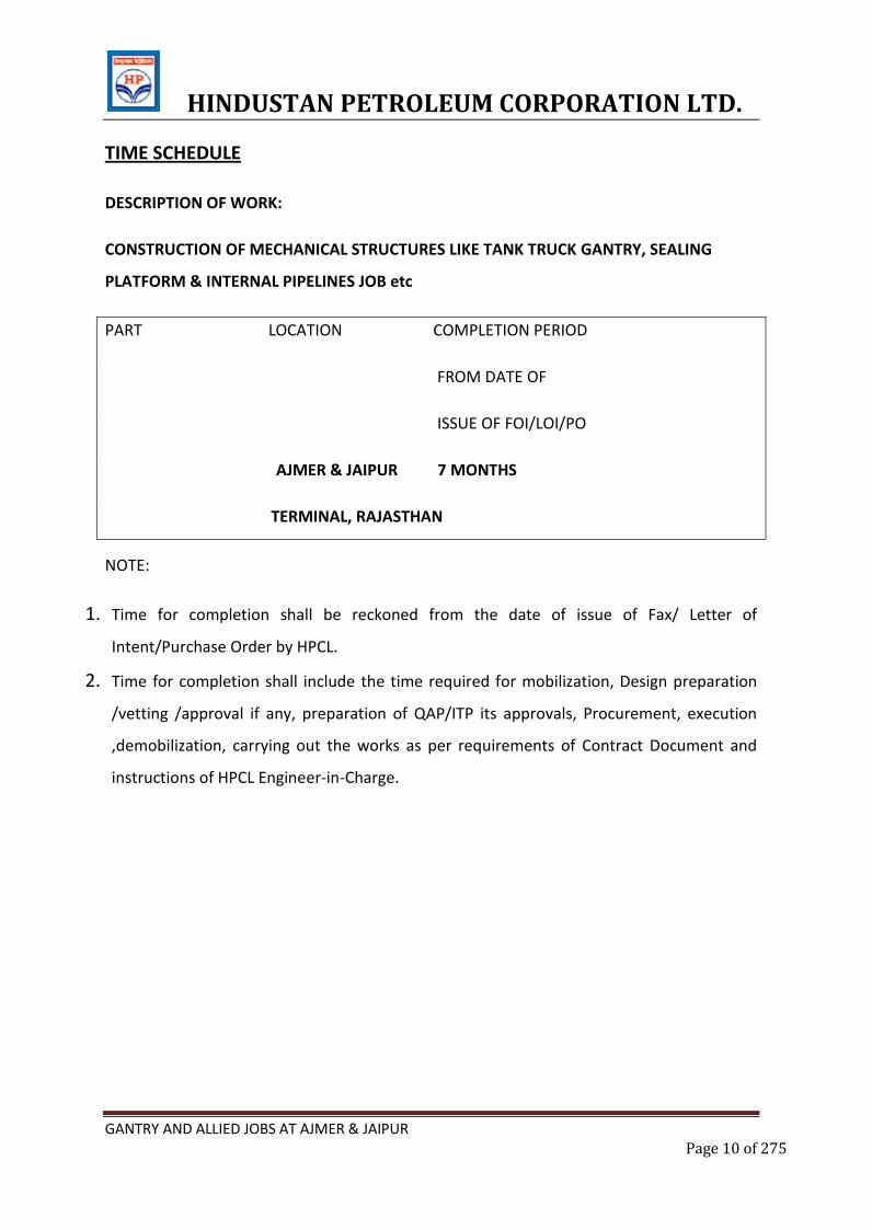
TIME SCHEDULE
DESCRIPTION OF WORK:
CONSTRUCTION OF MECHANICAL STRUCTURES LIKE TANK TRUCK GANTRY, SEALING
PLATFORM & INTERNAL PIPELINES JOB etc
PART LOCATION COMPLETION PERIOD
FROM DATE OF
ISSUE OF FOI/LOI/PO
AJMER & JAIPUR 7 MONTHS
TERMINAL, RAJASTHAN
NOTE:
1. Time for completion shall be reckoned from the date of issue of Fax/ Letter of
Intent/Purchase Order by HPCL.
2. Time for completion shall include the time required for mobilization, Design preparation
/vetting /approval if any, preparation of QAP/ITP its approvals, Procurement, execution
,demobilization, carrying out the works as per requirements of Contract Document and
instructions of HPCL Engineer-in-Charge.
HINDUSTAN PETROLEUM CORPORATION LTD.
GANTRY AND ALLIED JOBS AT AJMER & JAIPUR Page 11 of 275
E. TECHNICAL SPECIFICATIONS
HINDUSTAN PETROLEUM CORPORATION LTD.
GANTRY AND ALLIED JOBS AT AJMER & JAIPUR Page 12 of 275
SPECIFICATIONS FOR CIVIL JOBS
A. Specification for Earth work and filling.
B. Specification for Anti termite treatment.
C. Specification for Soling and hard core.
D. Specification for WBM base/ sub base.
E. Specification for concrete and reinforcement works.
F. Specification for Masonary and allied works.
G. Specification for plastering and pointing.
H. Specification for flooring and allied works.
I. Specification for painting, distempering & other finishing works.
J. Testing of building materials.
K. Norms of cement consumption.
L. Dimensional tolerances.
M. Method of measurement.
N. Safety requirements for construction works.
HINDUSTAN PETROLEUM CORPORATION LTD.
GANTRY AND ALLIED JOBS AT AJMER & JAIPUR Page 13 of 275
A. EARTH WORK AND BACKFILLING
1.0 SCOPE
1.1 This section of the specification covers the technical requirements for excavation and
filling & around structures, buildings, foundations, trenches, pits, drains, channels, tank
enclosure wall, roads, underground facilities & similar works. It also covers filling areas
and plinths with selected materials, conveyance and disposal of surplus spoils and/or
stacking them properly as directed by the EIC.
1.2 The contractor shall be fully responsible for proper setting out works, profiling in
excavation, stacking, etc. taking adequate safety measures etc. The Contractor shall
carry out all works meant within the intent of this specification even if not explicitly
mentioned herein. All works shall be executed to the satisfaction of the EIC.
1.3 Existing trees, shrubs, any other plants, pole lines, fences, signs, monuments, buildings,
pipelines, drains, sewers or other surface or subsurface systems/ drainage facilities
within or adjacent to the works being carried out which are not to be disturbed, shall
be protected from damage by the Contractor. The Contractor shall provide and install
suitable safeguards approved by the EIC for this purpose.
1.4 During excavation, the Contractor shall take all necessary precautions against soil
erosion, water & environmental pollution, and where required undertake additional
works to achieve this objective. Before start of operations, the Contractor shall submit
to the EIC for approval, his work plan and the procedure he intends to follow for
disposal of waste materials etc. and the schedule for carrying out temporary and
permanent control works. However, the approval of the EIC to such plans and
procedures shall not absolve the Contractor of his responsibility for safe and sound
work.
2.0 GENERAL
I. The Contractor shall make his own surveying arrangements for locating the
Coordinates and positions of all work and establishing the reduced levels (RL’s) at
these locations based on two reference of one bench mark which will be furnished
by the Owner. The Contractor has to provide at site all the required survey
HINDUSTAN PETROLEUM CORPORATION LTD.
GANTRY AND ALLIED JOBS AT AJMER & JAIPUR Page 14 of 275
instruments, along with qualified surveyors, to the satisfaction of the EIC so that the
work can be carried out accurately and according to the specification and drawings.
II. The Contractor shall furnish all skilled and unskilled labour, plant, tools, tackle,
equipment, men and materials required for complete execution of the work in
accordance with the drawings and as described herein and/or as directed by the
EIC.
III. The Contractor shall control the grade in the vicinity of all excavations so that the
surface of the ground will be properly sloped or dyked to prevent surface water
from running into the excavated areas during construction.
IV. All materials obtained from excavation shall remain the Owner’s property. All
salvaged materials of archeological importance or of value (in the opinion of the
EIC) shall be segregated from the other materials and both stacked separately and
in a regular manner at location indicated by the EIC.
V. Excavation shall include removal of trees including roots & organic remains,
vegetation, grass, bushes, shrubs, plants, poles, fences etc. that are in the area to be
excavated as well as beyond the excavation line so as to ensure safety of the
excavated side slopes and of men and equipment operating in the area. Before start
of excavation work, joint measurements of ground level shall be taken after clearing
all grass, vegetation etc.
VI. Excavation shall include the removal of all materials required to execute the work
properly and shall be made with sufficient clearance as decided by the EIC to permit
the placing and setting of forms, inspection and completion of all works to the
satisfaction of the EIC for which the excavation was done.
VII. Classification of Earth Work: The earth work shall be classified under the following
main categories.
All types of soils, murrum, boulders.
Soft rock.
Hard rock.
HINDUSTAN PETROLEUM CORPORATION LTD.
GANTRY AND ALLIED JOBS AT AJMER & JAIPUR Page 15 of 275
VIII. Ordinary soils: This includes earth, murrum, top deposits of agricultural soil,
reclaimed soil, clay, sand or any combination thereof and soft and hard murrum,
shingle etc., which is loose enough to be removed with spades shovel and pick axes.
Boulders not more than 0.03 cum. in volume found during the course of excavation
shall also fall under this classification.
IX. Soft Rock: This shall include all materials which are rock or hard conglomerate, all
decomposed weathered rock, highly fissured rock, old masonry, boulders bigger
than 0.03 cum in volume but not bigger than 0.5 cum and other varieties of soft
rock which can be removed only with pick axes, crow bars, wedges and hammers
with some difficulty. The mere fact that the contractor resorts to blasting and / or
wedging and chiseling for reasons of his own, shall not mean the rock is classifiable
as hard rock.
X. Hard Rock: This includes all rock other than soft rock mentioned in para IX viz. Soft
rock, occurring in masses, boulders having approximate volume more than 0.5 cum
plain or reinforced cement concrete, which can best be removed by blasting or
chiseling and wedging where blasting cannot be permitted owing to any restriction
at site.
3.0 CODES AND STANDARDS
3.1 All standards, specifications, acts and code of practice referred to herein shall be the
latest editions including all applicable official amendments and revisions.
3.2 .In case of conflict between this specification and those (IS standards, codes etc.)
referred to herein, the former shall prevail.
3.3 Some of the relevant Indian standards, Acts and Codes are referred to here below:
IS: 383 1970 Specification for coarse and fine aggregates from
natural sources for concrete.
IS 2720 (Part- 2) 1973 Methods of test for soils-Determination of water
content
HINDUSTAN PETROLEUM CORPORATION LTD.
GANTRY AND ALLIED JOBS AT AJMER & JAIPUR Page 16 of 275
IS 2720 (Part4-4
)
1985 Methods of test for soils-Grain size analysis
IS 2720 (Part-5 ) 1985 Methods of test for soils-Determination of liquid
limit & plastic limit
IS 2720 (Part-6 ) 1972 Methods of test for soils-Determination of
shrinkage factors
IS 2720 (Part-7 ) 1980 Methods of test for soils-Determination of water
content-Dry density relation using light
compaction
IS 2720 (Part-8 ) 1983 Methods of test for soils- Determination of water
content-Dry density relation using heavy
compaction
IS 2720 (Part-14
)
1983 Methods of test for soils-Determination of dry
index(relative density)
IS 2720 (Part-21
)
1977 Methods of test for soils-Determination of total
soluble solids
IS 2720 (Part-29
)
1975 Methods of test for soils-Determination of dry
density of soil in-place by core cutter method
IS: 3764 1992 Safety code for excavation work
IS: 9759 1981 Guide lines of dewatering during construction
IS: 10379 1982 Code of practice for field control of moisture and
compaction of soils for embankment and sub
grade
Indian Explosives Act 1940 as updated.
HINDUSTAN PETROLEUM CORPORATION LTD.
GANTRY AND ALLIED JOBS AT AJMER & JAIPUR Page 17 of 275
4.0 EXCAVATION IN SOIL
4.1 Side and bottom of excavation shall be cut sharp and true to line and level.
Undercutting shall not be permitted. When machines are used for excavation, the last
300 mm before reaching the required level shall be excavated manually or by such
equipment that soil at the required final level will be left in its natural condition.
Suitability of strata (at the bottom of excavations) for laying the foundation thereon
shall be determined by the HPCL EIC.
4.2 Excavation for foundation shall be to the bottom of lean concrete and as shown on
drawing or as directed by the EIC. The bottom of all excavations shall be trimmed to
required levels and when excavation is carried below such levels by error, it shall be
brought back to the specified level by filling with concrete of nominal mix 1:3:6 (cement:
coarse sand: 40 mm down aggregates) or / and as directed by the EIC.
4.3 The Contractor shall ascertain for himself the nature of materials to be excavated and
the difficulties, if any, likely to be encountered in executing this work., sheeting,
shoring,bracing, maintaining suitable slopes, draining etc. shall be provided and
installed by the Contractor, to the satisfaction of the EIC.
4.4. All excavation for installation of underground facilities, such as pipe lines, sewer line,
drain lines etc. shall be open cuts. For deep and huge excavations and in other
excavations, if required by the EIC, the Contractor shall submit for EIC’s approval an
“Excavation Scheme” showing the methodology to be adopted for excavation in order
to maintain the stability of side slopes, means for ensuring safety of existing facilities
nearby, dewatering. However, the Contractor shall be fully responsible for the scheme
irrespective of any approvals granted. Benching shall be provided for deeper excavation
wherever required.
4.5 When excavation requires bracing, sheeting or shoring etc. the Contractor shall submit
drawings to the EIC, showing arrangements and details of proposed installation. The
Contractor shall also furnish all supporting calculations as called for and shall not
proceed until he has received written approval from the EIC. However, the responsibility
for adequacy of such bracing, sheeting, shorting etc. will rest with the Contractor,
HINDUSTAN PETROLEUM CORPORATION LTD.
GANTRY AND ALLIED JOBS AT AJMER & JAIPUR Page 18 of 275
irrespective of any approval of the EIC.
4.6 The Contractor shall have to constantly pump out any water collected in excavated pits
and other areas due to rain water, springs etc. and maintain dry working conditions at
all times until the excavation, placement of reinforcement, shuttering, concreting,
backfilling is completed. The Contractor shall remove all slush/muck from the excavated
areas to keep the work area dry. Sludge pumps, if required, shall be employed by the
Contractor for this purpose.
4.7 The Contractor shall remove all materials arising from excavations from the vicinity of
the work either for direct filling, stacking the subsequent filling or for ultimate disposal
as directed by the EIC. In no case shall the excavated soil be stacked within a distance of
1.5 m from the edge of excavation or one third the depth of excavation whichever is
more. Material to be used for filling shall be kept separately.
5.0 EXCAVATION IN ROCK
5.1 General
5.1.1 All clauses from 4.1 to 4.7 shall be applicable to excavation in rock also. In case of any
discrepancy between the above mentioned clause and those specified in this clause then
this clause shall govern.
5.1.2 For the work of excavation in rock, Contractor shall engage specialised agency having
experience of excavation in rock involving wedging and blasting. The agency shall be
subject to approval of EIC and the Contractor shall furnish details of relevant experience in
support while seeking approval for the agency.
5.1.3 In case of over breaks in rock excavation, the excavated level shall be brought to the
level shown on drawings with plain cement concrete of nominal mix 1:3:6 as described in
para 4.02.00.
6.0 EXCAVATION BELOW GROUND WATER TABLE
6.1 Wherever ground water table is met with during excavation, the Contractor shall
immediately report this fact to the EIC who shall arrange to record the exact level of the
water table before start of dewatering operation. The decision of the EIC regarding sub-soil
water level shall be final and binding on the Contractor. Ground Water Table for the
purpose of this clause shall be taken as the level of standing water observed during the
HINDUSTAN PETROLEUM CORPORATION LTD.
GANTRY AND ALLIED JOBS AT AJMER & JAIPUR Page 19 of 275
process of excavation. Capillary action of water in the surrounding soil mass shall not be
considered for the above purpose.
6.2 The Contractor shall dewater and maintain dry working conditions by maintaining the
water table below the bottom of the excavation level by well-point dewatering or deep well
dewatering or any other method approved by the EIC. He shall continue doing so till
excavation, concreting, curing, and all other operation included in the scope of work, which
require dry condition in the area are completed.
7.0 LIFT
The Contractor is required to excavate upto any depth as shown on the drawings or as
directed by the EIC. Lifting of excavated materials shall be done either by manual or
mechanical or both means if called for by the EIC.
8.0 CARRIAGE OF MATERIALS
8.1 The EIC shall indicate the disposal/ stacking areas for excavated materials. The carriage
of excavated materials shall be done by the methods mentioned below:
a) The excavated materials shall be carried beyond the initial lead of 50 m but upto 500 m
by manual /animal labour or by mechanical means. If directed by the EIC this material
shall be used directly for filling purposes.
b) For leads exceeding 500 m the Contractor shall transport the excavated materials by
mechanical means only and as directed by the EIC. The Contractor may be allowed to
carry materials through Kuccha roads. Providing and maintaining of the Kuccha roads
shall be the responsibility of the Contractor. The transported material shall be neatly
stacked as directed by the EIC.
8.2 Some excavated materials required for filling purposes, may have to be carried upto a
lead of 500 m and stacked as per instructions of the EIC. Excavated materials carried
beyond 500 m shall normally be for disposal purpose only. Double handling of materials
shall be avoided as far as possible. However, depending on site condition excavated
materials carried beyond a lead of 500 m may also be required to be brought back for filling
purpose.
9.0 FILLING
9.1 Materials
HINDUSTAN PETROLEUM CORPORATION LTD.
GANTRY AND ALLIED JOBS AT AJMER & JAIPUR Page 20 of 275
9.1.1Materials to be used for filling purpose shall be stone, sand or other inorganic
materials and they shall be clean and free from shingle, salts, organic matter, large roots
and excessive amount of sod, lumps, concrete or any other foreign substances which could
harm or impair the strength of the substances in any manner. All clods shall be suitably
broken to small pieces. When the materials are mostly rock boulders, these shall be broken
into pieces not larger then 150 mm size. Murrum / Sand used for filling shall be clean,
medium grained and free from impurities. Fines less than 75 microns shall not be more
than 20%. In any case, the materials to be used for filling purposes shall have the prior
written approval of the EIC.
9.1.2 If excavated materials are to be used for filling, then the Contractor shall select the
materials from the stockpile, land and transport this material and execute the filling. This
shall include excavation of earth, which may become hard due to lying in stockyard for a
long period of time.
9.1.3 In case the materials have to be brought from pits/quarries, it shall be the
Contractor’s responsibility for identification of such quarry areas, obtaining approval from
their use from concerned authorities, excavation/quarrying loading and carriage of such
material, unloading and filling at specified locations. The Contractor shall pay any fees,
royalties etc. that may have to be paid for utilisation of borrow areas.
9.2 Filling Procedure
9.2.1 After completion of foundation, footings, walls and other construction below the
elevation of the final grades, and prior to filling, all temporary shoring, timber etc. shall be
sequentially removed and the excavation cleaned of all trash, debris, and. perishable
materials. Filling shall begin only with the written approval of the EIC. Also, areas identified
for filling shall be cleared of all soft pockets, vegetation, bushes, slash etc. In case of plinth
and similar filling the ground shall be dressed and consolidated by ramming and light
rolling.
9.2.2 Fill materials shall not be dropped directly upon or against any structure or facility
where there is danger of displacement or damage. Filling shall be started after the
concrete/masonry has fully set and shall be carried out in such a manner so as not to cause
any undue lateral thrust on any part of the structure.
HINDUSTAN PETROLEUM CORPORATION LTD.
GANTRY AND ALLIED JOBS AT AJMER & JAIPUR Page 21 of 275
9.2.3 All space between foundation (concrete or masonry) and the sides excavation shall be
filled to the original surface after making allowance for settlement, Fill shall be placed in
horizontal layers not exceeding 200 mm loose thickness. Each layer shall be watered and
compacted with proper moisture content and with such equipment as may be required to
obtain a compaction/density as specified. Trucks or heavy equipment for depositing or
compacting fill shall not be used within 1.5 meters of building walls, piers for operation.
The methods of compaction shall be subjected to approval of EIC under any circumstances.
9.2.4 Fill adjacent to pipes shall be free of stones, concrete etc. and shall be hand placed
and compacted uniformly on both sides of the pipe and where practicable up to a minimum
depth of 300 mm over the top of pipes. While tamping around the pipes, care should be
taken to avoid unequal pressure.
9.2.5 Filling shall be accurately finished to line, slope, cross section and grade as shown on
the drawings. Finished surface shall be free of irregularities and depressions and shall be
within 20 mm of the specified level.
9.2.6 Where filling with stone from excavated materials is specified, it shall be from broken
pieces of boulders. At first a 75 mm thick cushion of selected earth shall be laid over which
the 200 mm thick graded stones shall be laid in loose layers of 200 mm then the interstices
filled with properly graded fine materials consisting of selected earth brought from borrow
areas. Each layer shall be watered and compared to the specified density before the next
layer is laid. However, no cushion shall be required where filling is over non-rocky surface.
9.2.7 Where filling with 65 mm downgraded stone obtained from excavated, it shall be
selected stone laid over and initial 50 mm thick cushion layer of selected earth and then
stone laid in 200 m loose thick layers, interstices filled with the specified density before the
next layer in laid. However, no cushion shall, be required where filling isover non-rocky
surface.
9.2.8 Where clean stone fill is specified, it shall consist of clean selected stone metal of 40-
mm nominal size. It shall be laid in layers not exceeding 150 mm (loose) and lightly tamped
before the next layer is laid. No compaction shall be required for this type stone filling.
9.3 Compaction
9.3.1 Where compaction to 85% Standard Proctor Density or more is called for, it shall be
HINDUSTAN PETROLEUM CORPORATION LTD.
GANTRY AND ALLIED JOBS AT AJMER & JAIPUR Page 22 of 275
by mechanical means only. Where access is possible, compaction shall be by 10 tonne
rollers smooth wheeled, sheep foot or wobbly wheeled as directed by the EIC. A smaller
weight roller may be permitted by the EIC in special cases, but in any case not less than 10
passes of the roller will be accepted for each layer. Each layer shall be wetted or the
material dried by aeration to moisture content of 3-5% above the Optimum Moisture
Content to be determined by the Contractor. Each layer shall be watered, rammed and
compacted to the density as specified EIC.
9.3.2 For compacting sand layer, water shall be sprayed over it to flood it and it shall be
kept flooded for 24 hours to ensure maximum compaction. Vibro-compactors shall also be
used if necessary to obtain the required degree of compaction. Any temporary works
required to contain sand under flooded condition shall also be undertaken. The surface of
the consolidated sand shall be dressed to required levels or slope.
9.3.3 After the compacted fill has reached the desired level, the surface shall be flooded
with water for 24 hours, allowed to dry and then rammed and consolidated to avoid any
settlement, at a later date. The compacted surface shall be properly shaped, trimmed and
consolidated to an even gradient or level. All soft spots shall be excavated, filled and
consolidated.
9.3.4 The degree of compaction of compacted fill in place will be subject to tests by the EIC
as the work progresses, and the contractor shall provide the necessary facilities to make
such tests. If any test indicates that the compaction achieved is less than the specified
degree of compaction, the EIC may require fill placed subsequent to the last successful test
to be removed and re-compacted by the Contractor. Compaction procedure shall be
amended as necessary to obtain satisfactory results.
9.3.5 When semi-compacted fill is specified by the EIC, the contractor shall fill up such areas
with available earth from stock piles of borrow pits or directly from excavation without
special compaction except that obtained by moving trucks etc.
10.0 SAMPLING, TESTING AND QUALITY CONTROL
10.1 General
10.1.1 The contractor shall carry out all sampling and testing in accordance with the
relevant Indian Standards and/or International Standards and shall conduct such tests as
HINDUSTAN PETROLEUM CORPORATION LTD.
GANTRY AND ALLIED JOBS AT AJMER & JAIPUR Page 23 of 275
are called for by the EIC. Where no specific testing procedure is mentioned, the tests shall
be carried out as per the prevalent accepted EIC ringing practice to the directions of the
EIC. Tests shall be done in the field and at a laboratory approved by the EIC and the
Contractor shall submit to the EIC, the test results in triplicate within three days after
completion of a test. The EIC may, at his discretion, waive some of the stipulations given
below, for small and unimportant operations.
10.1.2 Work found unsuitable for acceptance shall be removed and replaced by the
contractor. The work shall be redone as per specification requirements and to the
satisfaction of the EIC.
10.1.3 Only as a very special case aid that too in non-critical areas, the EIC may accept filling
work which is marginally unacceptable as per the criteria laid down. For such accepted
work, payment shall be made at a reduced rate pro-rata to the compaction obtained
against that stipulated.
10.2. Quality Assurance Program
The contractor shall submit and finalize a detailed field Quality Assurance Program
within 30 days from the date of award of the Contract according to the requirements of the
specification. This shall include identification of approved testing laboratory, arrangement
of field testing apparatus/equipment, deployment of qualified/experienced manpower,
preparation of format for record, Field Quality plan etc. On finalized field quality plan the
Owner shall identity Customer hold points beyond which work shall not proceed without
written approval from the EIC.
10.3 Frequency of sampling and testing including the methods for conducting the tests shall
be as per IS codal provisions. The testing frequencies set forth are the desirable minimum
and the EIC shall have the full authority to carry out or call for tests as frequently as he may
deem necessary to satisfy himself that the materials and work comply with the appropriate
specifications.
10.4 Acceptance Criteria
10.4.1 Following Acceptance Criteria shall be as under:
a) All individual samples collected and tested should pass without any deviation when only
one set of sample is tested.
HINDUSTAN PETROLEUM CORPORATION LTD.
GANTRY AND ALLIED JOBS AT AJMER & JAIPUR Page 24 of 275
b) For re-test of any sample two additional samples shall be collected and tested and both
should pass without any deviation.
c) Where a large number of samples are tested for a particular test, 9 samples out of
every 10 consecutive samples tested shall meet the specification requirement.
d) Tolerance on finished levels for important filling areas at approved interval shall be + 20
mm. However, for an unimportant area, tolerance upto + 75 mm shall be acceptable at
the discretion of the EIC. However, these tolerances shall be applicable for localised
areas only.
HINDUSTAN PETROLEUM CORPORATION LTD.
GANTRY AND ALLIED JOBS AT AJMER & JAIPUR Page 25 of 275
B. ANTITERMITE TREATMENT
1.0 GENERAL
1.1 Pre-constructional anti – termite treatment is a process in which soil treatment is
applied to a building in early stages of its construction. The purpose of anti-termite
treatment is to provide the building with a chemical barrier against the sub-terranean
termites.
1.2 Anti termite treatment being a specialized job, calls for through knowledge of the
chemicals, soils, termite to be dealt with and the environmental conditions, in order to
give effective treatment and lasting protection to the property undergoing treatment.
It is therefore, imperative that the works of anti-termite treatment should be got
executed through specialized agencies only. The specialized agency should be
preferably a member of the Indian Pest Control Association and shall have sufficient
experience of carrying out similar works of magnitude envisaged in this tender.
1.3 The pre-constructional soil treatment is required to be applied during the construction
stages of the sub-structure upto plinth level. The contractor has to be watchful of the
various stages of sub-structure works and arrange to carry out the soil treatment in
time after proper co-ordination with other constructors if any, working at site.
1.4 The scope of pre-constructional anti-termite treatment covers the soil treatment with
approved chemicals in water emulsion in foundation trenches for columns, plinth
beams, brick walls, service trenches, lift pits, steps, ramps etc., in top surfaces of plinth
filling, at junction of walls and floor, in expansion joints etc., in stages as detailed in this
specifications and drawings, unless otherwise stipulated, the anti-termite treatment will
be carried out as per IS : 6313 (Part-II) and / or as per direction of the EIC.
2.0 CODES & STANDARDS
The relevant Indian Code for Anti-termite treatment is given below:
IS 6313 (Part 2) 2001 Anti-termite measures in building – Pre construction
chemical treatment
HINDUSTAN PETROLEUM CORPORATION LTD.
GANTRY AND ALLIED JOBS AT AJMER & JAIPUR Page 26 of 275
3.0 SITE PREPARATION
3.1 In order to ensure uniform distribution of the chemical emulsion and to assist
penetration, the following site preparation shall be carried out:
a) Remove all trees, stumps, logs or roots from the building site.
b) Remove all concrete from work if left anywhere, leveling pegs, timber off-cuts and
other builders debris from the area to be treated.
c) If the soil to be treated is sandy or porous, preliminary moistening will be required to fill
capillary spaces in soil in order to prevent the loss of emulsion through piping or
excessive percolations.
d) In the event of water logging of foundation, the water shall be pumped out before
application of chemical emulsion and it should be applied only when the soil is
absorbent.
e) On clays and other heavy soils where penetration is likely to be slow and on sloping
sites, where run-off of the treating solution is likely to occur, the surface of the soil
should be scarified to a depth of 75 mm at least.
f) All sub floor leveling and grading should be completed, all cutting, trenches and
excavations should be completed with back filling in place, borrowed fill must be free
from organic debris and shall be well compacted. If this is not done supplementary
treatments should be made to complete the barrier.
4.0 CHEMICAL TO BE USED
4.1 The effectiveness of chemical depends upon the choice of the chemical, the dosage
adopted and the thoroughness of application. The chemical solutions or emulsions are
required to be dispersed uniformly in the soil and to the required strength so as to form
an effective chemical barrier which is lethal and repellent to termites.
4.2 The following chemical in water emulsion, after approval from the EIC, shall be used
uniformly over the area to be treated.
Chlropyrophos
HINDUSTAN PETROLEUM CORPORATION LTD.
GANTRY AND ALLIED JOBS AT AJMER & JAIPUR Page 27 of 275
4.3 The contractor should produce voucher (s) for the chemical purchased and should get
verified the sealed container(s) of the specified chemical from the EIC in-Charge before
preparing the emulsion / use for the treatment.
5.0 MODE AND RATE OF APPLICATION:
5.1 The chemical emulsion as stated above will be applied uniformly by sprayers at the
prescribed rates as detailed below in all the stages of the treatment.
5.2 Treatment in Foundation Trenches: In case of normal wall load bearing structures,
column pits, wall trenches and basement, the treatment shall be at a rate of5ltrs./sqm of
surface area of the bottom and sides to a height of at least 300 mm. After the foundation
work, the sides shall be treated at a rate of 7.5 ltrs./sqm of vertical surface of substructure
on each side. After the earth filling is done, treatment shall be done by rodding the earth at
150 mm centers close to wall surface and spraying the chemical with the above dose i.e.
7.5 ltrs./sqm. In case of framed structure, the treatment shall start at a depth of 500mm
below ground level. From this depth the backfill around the columns, beams and R.C.C.
basement walls shall be treated at a rate of7.5 ltrs./sqm of the vertical surface and at a
rate of 5 ltrs / sqm for the horizontal surface at the bottom in the trenches / pits
5.3 Treatment on Top Surfaces of Plinth Filling: The top surface of the filled earth
within plinth walls shall be treated with chemical emulsion at the rate of 5 litres / sqm of
the surface area before sub-base to floor is laid, if filled earth has been well rammed and
the surface does not allow the emulsion to seep through, holes upto 50 to 75mm deep at
150mm centers both ways shall be made with crow bars on the surface to facilitate
saturation of the soil with the emulsion.
5.4 Treatment at Junction of Walls and Floors : Special care shall be taken to establish
continuity of the vertical chemical barrier on the inner wall surfaces from the finished
ground level (or from level where the treatment had stopped) upto the level of the filled
earth surface. To achieved this a small channel 30 x 30 mm shall be made at all the
junctions of wall / column with floor (before laying sub-grade) and rod holes made in the
channel upto the finished ground level at 150 mm apart and the iron and moved
backward and forward to break the earth and chemical emulsion poured along the
HINDUSTAN PETROLEUM CORPORATION LTD.
GANTRY AND ALLIED JOBS AT AJMER & JAIPUR Page 28 of 275
channel at a rate of 7.5 litres (or at recommended quantity) per sqm. of the vertical wall /
column surfaces so as to soak the soil right up to the bottom. The soil shall be tamped
back into place after this operation.
5.5 Treatment for Expansion Joints: The soil beneath the expansion joints shall receive
special attention when the treatment under 5.02.00 above is in progress. This treatment
shall be supplemented by treating through the expansion joint after sub-grade has been
laid at the rate of 2 litres per metre length of expansion joint.
6.0 PRECAUTIONS
6.1 Utmost care shall be taken to see that the chemical barrier is complete and
continuous. Each part of the area shall receive the prescribed dosage of chemical
emulsion.
6.2 The treatment should not be carried out when it is raining or when the soil is wet
with rain or sub-soil water.
6.3 Once formed, the treated soil barrier shall not be disturbed. If by chance, treated
soil barriers are disturbed, immediate steps shall be taken to restore the continuity and
completeness of the barrier system.
7.0 HEALTH HAZARDS AND SAFETY MEASURES
7.1 All the chemicals mentioned above are poisonous and hazardous to health. These
chemicals can have an adverse effect upon health when absorbed through the skin, inhaled
as vapours or spray mist or swallowed. Persons handling or using these chemicals should be
warned of these dangers and advised that absorption through the skin is the most likely
source of accidental poisoning. They should be cautioned to observe carefully the safety
precautions given in 7.02.00 to 7.05.00 particularly when handling these chemicals in the
form of concentrates.
HINDUSTAN PETROLEUM CORPORATION LTD.
GANTRY AND ALLIED JOBS AT AJMER & JAIPUR Page 29 of 275
7.2 These chemicals are usually brought to the site in the form of emulsifiable
concentrates. The containers should be clearly labeled and should be stored carefully so
that children and pets cannot get at them. They should be kept securely closed.
7.3 Particular care should be taken to prevent skin contact with concentrates.
Prolonged exposure to dilute emulsions should also be avoided. Workers should wear
clean clothing and should wash thoroughly with soap and water specially before eating and
smoking. In the event of severe contamination, clothing should be removed at once and
the skin washed with soap and water. If chemicals splash into the eyes they shall be
flushed with plenty of soap and water and immediate medical attention should be sought.
7.4 The concentrates are oil solutions and present a fire hazard owing to the use of
petroleum solvents. Flames should not be allowed during mixing.
7.5. Care should be taken in the application of chemicals / soil – toxicants to see that
they are not allowed to contaminate wells or springs which serve as source of drinking
water.
HINDUSTAN PETROLEUM CORPORATION LTD.
GANTRY AND ALLIED JOBS AT AJMER & JAIPUR Page 30 of 275
C. SOLING & HARDCORE
1.0 GENERAL
1.1 The work covered under this specification includes all type of soling work either by
rubble stones laid under floors / hard core under foundations, hand packed, complete as
per under mentioned specification and applicable drawings.
2.0 RUBBLE STONE SOLING
2.1 The rubble stone shall be of best variety of black trap / granite / basalt or other
approved variety of stone available locally. The stone shall be hard, durable, free from
defects and of required size and shall be approved by the Engineer in-charge before
incorporation in the work.
2.2 Preparation of Surface & laying:
2.2.1 The bed on which rubble soling is to be laid shall be cleared of all loose materials,
leveled, watered and compacted and got approved by the Engineer In-charge before laying
rubble soling. Cable or pipe trenches if shown in the drawing and as required by the
Engineer in-charge shall be got done before the soling is started.
2.2.2 Over the prepared surface, the stone shall be set as closely as possible and well
packed and firmly set. The stones shall be of full height and shall be laid so as to have their
bases of the largest area resting on the sub-grade. Soling shall be laid in one layer of
230mm or other specified thickness and no stones shall be less than 230mm depth or
specified thickness of soling with a tolerance of 25mm.
2.2.3 After packing the stones properly in position, the interstices between them shall be
carefully filled with quarry spoils of stone chips of larger size possible to obtain a hard,
compact surface. Spreading of loose spoils or stone chips is prohibited.
2.2.4 The entire surface shall be examined for any protrusions and the same shall be
HINDUSTAN PETROLEUM CORPORATION LTD.
GANTRY AND ALLIED JOBS AT AJMER & JAIPUR Page 31 of 275
knocked off by a hammer and all interstices shall be filled with approved murrum.
Excess murrum if any over the surfaces shall be removed. Unless otherwise specified,
the murrum shall be supplied by the contractor at his own cost from the selected
areas. The surfaces shall then be watered and consolidated with mechanical or
sufficiently heavy wooden tampers and log-rammers as approved by the Engineer in-
charge to give the required slope or level and dense sub-base. After compaction, the
surface shall present clean look. Adequate care shall be taken by the contractor while
laving and compacting the rubble soling to see that concrete surfaces in contact with
soling are not damaged.
3.0 HARD CORE FOR FOUNDATIONS
3.1 Where specifically mentioned in the drawings, hard core layer shall be provided as a
preparatory surface to receive blinding concrete/ leveling course.
3.2 Hard core layer shall comprise of well graded broken stones 80mm nominal size with
the following gradation:
IS Sieve designation % passing
80 mm 100
63 mm 85-100
40 mm 0-30
20 mm 0-5
10 mm 0-5
3.3 The hard broken stones layer shall be directly placed over the compacted layer of under
lying soil in layers. The stones shall be hand packed and crevices filled with broken
stones.
HINDUSTAN PETROLEUM CORPORATION LTD.
GANTRY AND ALLIED JOBS AT AJMER & JAIPUR Page 32 of 275
3.4 Each layer shall be covered with clean river sand and thoroughly worked into the
crevices with a water jet. Additional layers of sand shall be placed on top and worked
into the void spaces. The process shall be repeated until no more sand and water get
into the voids.
3.5 Earth rammer shall be used to compact each layer if directed by EIC.
3.6 The thickness and area covered beyond the blinding concrete shall be as indicated in
the drawings or as indicated by EIC.
HINDUSTAN PETROLEUM CORPORATION LTD.
GANTRY AND ALLIED JOBS AT AJMER & JAIPUR Page 33 of 275
D. CONSTRUCTION OF WBM BASE/SUBBASE FOR ROADS/DRIVEWAY
WBM SUB BASE/BASE COURSE
1. SCOPE
1.1 This work shall consist of clean crushed aggregates mechanically interlocked by rolling
and bonded together with screening, binding material where necessary and water laid on a
properly prepared sub grade /sub base/base or existing pavement, as in case may be and
finished in accordance with the requirements of these specification and in close conformity
with the lines, grade, cross section and thickness as per approved plans or as directed by
the engineer.
1.2 it is however, not desirable to lay WBM on an existing thin black topped surface without
providing adequate drainage facility for water that would get accumulated at the interface
of existing bituminous surface and WBM.
2. MATERIAL
2.1 Coarse aggregate
2.1.1 General requirement
Coarse aggregates shall be either crushed or broken stone ,crushed slag ,over burnt brick
aggregates or any other naturally occurring aggravates such as kankar ,laterites of suitable
quality (which shall be used in sub base course only)the aggregates shall conform to the
physical requirements set forth in table 1.0. The type and size range of the aggregates shall
be specified in contract or shall be specified by the Engineer.
Table 1.0
Test Test method Requirement
Los Angeles abrasion value IS:2386( PART –IV)
50% Max.
HINDUSTAN PETROLEUM CORPORATION LTD.
GANTRY AND ALLIED JOBS AT AJMER & JAIPUR Page 34 of 275
Aggregates impact value IS:2386( PART –IV)
Or IS 5640
40% max.
Flakiness index IS 2386 (PART- I) 15% max.
2.2 CRUSHED OR BROKEN STONE
The crushed or broken stone shall be hard, durable and free from exc4ss flat, elongated,
soft and disintegrated particles, dirt and other deleterious material.
2.3 CRUSHED SLAG
Crushed slag shall be made from air cooled blast furnace slag. It shall be of angular shape,
reasonably uniform in quality and density and generally free from thin elongated and soft
pieces, dirt or other deleterious materials. The weight of crushed slag shall not be less than
1120 kg per m^3 and the % of glossy material shall not be more than 20. It should also
comply with the following requirement:
1. Chemical stability:-to comply with requirement of appendix of BS 1047
2. Sulpher content:-max.:-2%
3. Water absorption: - max.10%
2.4 OVERBURNT (JHAMA) BRICK AGGRAGATES
Jhama brick aggregates shall be made from over burnt bricks or bricks bats and be free
from dust and other objectionable and deleterious materials.
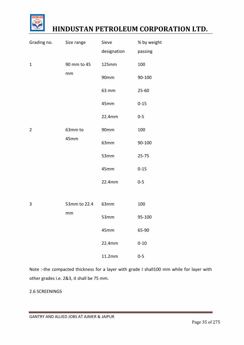
2.5 GRADING REQUIREMENT OF COARSE AGGRAGATES
The coarse aggregates shall conform to one of the grading given in tales 2.0 as specified,
provided ,however ,the use of grading no. 1 shall be restricted to sub base course only.
Table 2.0 grading requirements of coarse aggregates
HINDUSTAN PETROLEUM CORPORATION LTD.
GANTRY AND ALLIED JOBS AT AJMER & JAIPUR Page 35 of 275
Grading no. Size range Sieve
designation
% by weight
passing
1 90 mm to 45
mm
125mm
90mm
63 mm
45mm
22.4mm
100
90-100
25-60
0-15
0-5
2 63mm to
45mm
90mm
63mm
53mm
45mm
22.4mm
100
90-100
25-75
0-15
0-5
3 53mm to 22.4
mm
63mm
53mm
45mm
22.4mm
11.2mm
100
95-100
65-90
0-10
0-5
Note :-the compacted thickness for a layer with grade I shall100 mm while for layer with
other grades i.e. 2&3, it shall be 75 mm.
2.6 SCREENINGS
HINDUSTAN PETROLEUM CORPORATION LTD.
GANTRY AND ALLIED JOBS AT AJMER & JAIPUR Page 36 of 275
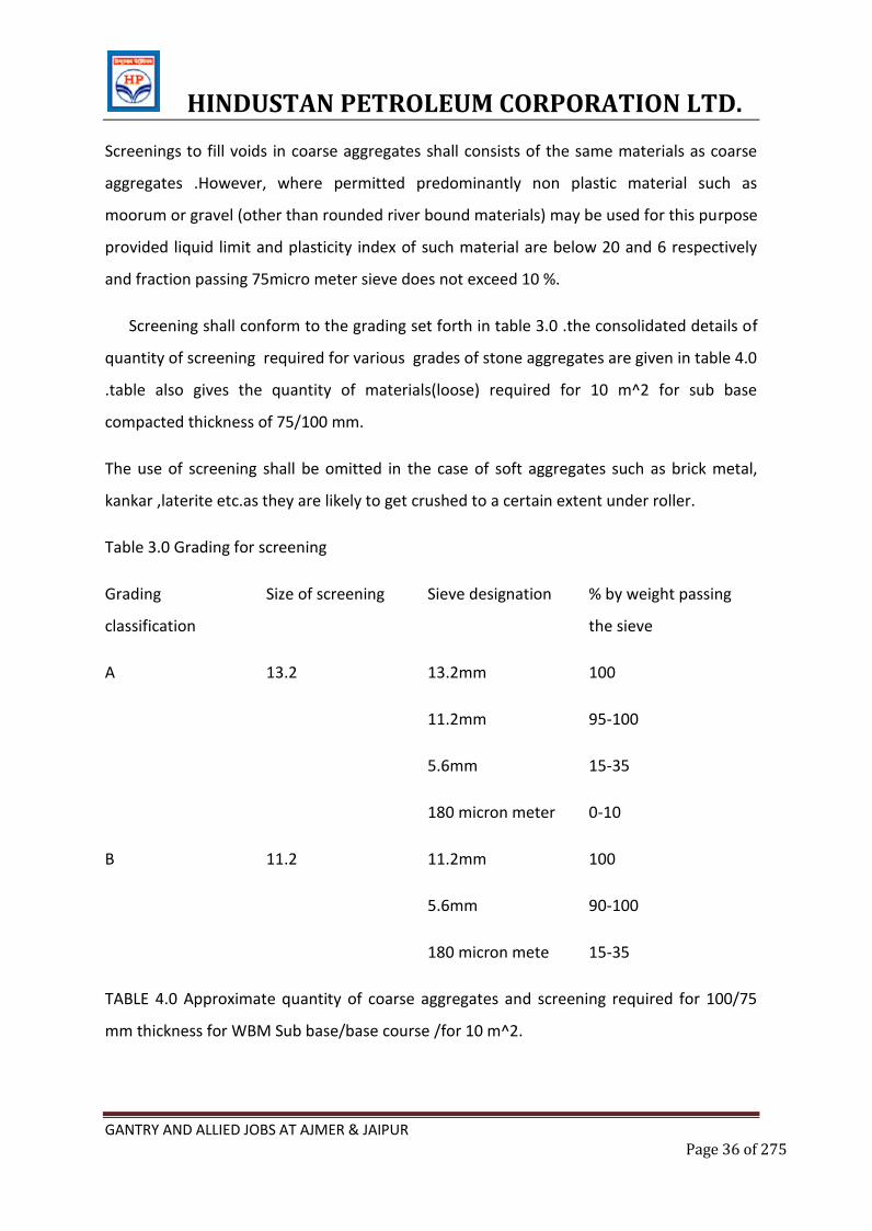
Screenings to fill voids in coarse aggregates shall consists of the same materials as coarse
aggregates .However, where permitted predominantly non plastic material such as
moorum or gravel (other than rounded river bound materials) may be used for this purpose
provided liquid limit and plasticity index of such material are below 20 and 6 respectively
and fraction passing 75micro meter sieve does not exceed 10 %.
Screening shall conform to the grading set forth in table 3.0 .the consolidated details of
quantity of screening required for various grades of stone aggregates are given in table 4.0
.table also gives the quantity of materials(loose) required for 10 m^2 for sub base
compacted thickness of 75/100 mm.
The use of screening shall be omitted in the case of soft aggregates such as brick metal,
kankar ,laterite etc.as they are likely to get crushed to a certain extent under roller.
Table 3.0 Grading for screening
Grading
classification
Size of screening Sieve designation % by weight passing
the sieve
A 13.2 13.2mm
11.2mm
5.6mm
180 micron meter
100
95-100
15-35
0-10
B 11.2 11.2mm
5.6mm
180 micron mete
100
90-100
15-35
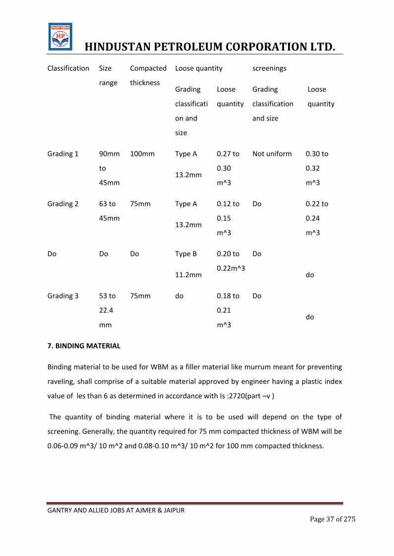
TABLE 4.0 Approximate quantity of coarse aggregates and screening required for 100/75
mm thickness for WBM Sub base/base course /for 10 m^2.
HINDUSTAN PETROLEUM CORPORATION LTD.
GANTRY AND ALLIED JOBS AT AJMER & JAIPUR Page 37 of 275
Classification Size
range
Compacted
thickness
Loose quantity screenings
Grading
classificati
on and
size
Loose
quantity
Grading
classification
and size
Loose
quantity
Grading 1 90mm
to
45mm
100mm Type A
13.2mm
0.27 to
0.30
m^3
Not uniform 0.30 to
0.32
m^3
Grading 2 63 to
45mm
75mm Type A
13.2mm
0.12 to
0.15
m^3
Do 0.22 to
0.24
m^3
Do Do Do Type B
11.2mm
0.20 to
0.22m^3
Do
do
Grading 3 53 to
22.4
mm
75mm do 0.18 to
0.21
m^3
Do
do
7. BINDING MATERIAL
Binding material to be used for WBM as a filler material like murrum meant for preventing
raveling, shall comprise of a suitable material approved by engineer having a plastic index
value of les than 6 as determined in accordance with Is :2720(part –v )
The quantity of binding material where it is to be used will depend on the type of
screening. Generally, the quantity required for 75 mm compacted thickness of WBM will be
0.06-0.09 m^3/ 10 m^2 and 0.08-0.10 m^3/ 10 m^2 for 100 mm compacted thickness.
HINDUSTAN PETROLEUM CORPORATION LTD.
GANTRY AND ALLIED JOBS AT AJMER & JAIPUR Page 38 of 275
The above mentioned quantities should be taken as a guide only, for estimation of
quantities of construction, etc. application of binding materials may not be necessary when
the screenings used are of crushable type such as murrum or gravel.
3. Construction Operation
3.1 Preparation of base
The surface of the sub –grade/sub –base/base to receive the WBM course shall be
prepared to the specified lines and cross fall (camber)and made free of dust and other
extraneous material. Any ruts or soft yielding places shall be corrected in an approved
manner and rolled until firm Sub base/base surface irregularities, where predominant ,
shall be made good by providing appropriate type of profile corrective course to clause 501
of these specification.
As far as possible ,laying WBM course over an existing thick ,bituminous layer may be
avoided since it will cause problem of internal drainage of pavement at the interface of two
courses .it is desirable to completely pick out the existing thin bituminous wearing course
where WBM is proposed to be laid over it .however ,in exceptional cases ,where the
intensity of rain is low and the interface drainage facility is efficient WBM can be laid over
the existing thin bituminous surface by cutting 50mmx50mm furrows at an angle of 45
degree to the center line of pavement at one meter intervals in the existing road .the
directions and depth of furrows shall be such that they provide adequate bondage and also
serve to drain water to the existing granular base course beneath the existing thin
bituminous surface.
3.2 INVERTED CHOKE
If the WBM is to be laid directly over the subgrade, without any other intervening
pavement course a 25 mm coarse of screening (Grading B)or coarse sand shall be spread on
the prepared sub grade before application of the coarse aggregates is taken up.in the case
of fine sand or silty or clay sub grade ,it is advisable to lay 100 mm insulating layer of
screening or coarse sand on top of fine grained soil, the gradation of which will depend on
HINDUSTAN PETROLEUM CORPORATION LTD.
GANTRY AND ALLIED JOBS AT AJMER & JAIPUR Page 39 of 275
whether it is intended to act as a drainage layer as well .alternatively ,appropriate
geosynthetics performing function of separation and drainage may be used over the
prepared sub grade as directed by the engineer.
3.3 SPREADING COARSE AGGREGATES
The coarse aggregate shall be spread uniformly and evenly upon the prepared sub grade
/sub base/base to proper profile by using templates placed across the road about 6 m
apart, in such quantities that thickness of each compacted layer is not more than 100mm
for grading 1 and 75mm for grading 2 and 3 ,as specified in clause 2.5. Wherever possible,
approved mechanical devices shall be used to spread the aggregates uniformly so as to
minimize the needs for manual rectification onwards .aggregates placed at location which
are inaccessible to the spreading equipment, may be spread in one or more layer by any
approved means so as to achieve the specified results.
The spreading shall be done from stockpiles along the side of the roadways or directly
from vehicles. in no case shallthe aggregates be dumped in heaps directly on the surface
prepared to receive the aggregates nor shall hauling over uncompacted or partially
compacted base shall be allowed and the coarse aggregate as spread shall be of uniform
gradation with no pockets of fine material.
The surface of the aggregate spread shall be carefully checked with templates and all high
and low spots remedied by removing or adding aggregates as may be required .the surface
shall be checked frequently with a straight edge while spreading and rolling so as to ensure
a finished surface as par approved plan.
The coarse aggregate shall not normally be spread more than three days in advance of the
subsequent construction operation.
3.4 ROLLING
Immediately following the spreading of the coarse aggregate, rolling shall be started with
three wheeled power roller s of 8 to 10tone capacity or tandem or vibratory rollers of
HINDUSTAN PETROLEUM CORPORATION LTD.
GANTRY AND ALLIED JOBS AT AJMER & JAIPUR Page 40 of 275
approved type . The type of roller to be used shall be approved by the engineer based on
trial run.
Except on super elevated portions where the rolling shall proceed from inner edge to outer,
rolling shall begin from the edge gradually progressing towards center .first the edge/edges
shall be compacted with roller running forwards and backwards. the roller shall then move
inwards parallel to the center line of road ,in successive passes uniformly lapping preceding
track by at least one half width.
Rolling shall be discontinued when the aggregate are partially compacted with sufficient
void space in them to permit application of screenings. However, when screening are not to
be applied ,as in the case of crushed aggregates like brick metal,laterites and
kankar,compaction shall be continued until the aggregates are thoroughly keyed. During
rolling, slight sprinkling of water may be done, if necessary. Rolling shall not be done when
the sub grade is soft or yielding or when it causes a wave like motion in the sub grade or
sub base course.
The rolled surface shall be checked transversely and longitudinally .with templates and any
irregularity corrected by loosening the surface, adding
or removing necessary amount of aggregates and re-rolling until entire surface conforms
to desired cross fall(camber) and grade. In no case screening be permitted to makeup
depressions.
Materials which are crushed excessively during compaction or become segregated shall be
removed and replaced with suitable aggregates.
It shall be insured that shoulders are built up simultaneously along with WBM courses.
3.5 APPLICATION OF SCREENING
After the coarse aggregates has been rolled to clause 3.4 screenings to completely filled fill
the interstices shall be applied gradually over the surface. these shall not be damp or wet at
time of application dry rolling shall be done while the screening are being spread so that
HINDUSTAN PETROLEUM CORPORATION LTD.
GANTRY AND ALLIED JOBS AT AJMER & JAIPUR Page 41 of 275
vibration of roller cause them to settle into the voids of the coarse aggregates .the
screening shall not dumped in piles but be spread uniformly in successive thin layer either
by the spreading motion of hand shovels or by mechanical spreaders or directly from tipper
with suitable grit spreading arrangement .tipper operating for spreading the screenings
shall be so driven as not to disturb the coarse aggregates. the screening shall be applied in
at a slow and uniform rate(in three or more applications) so as to ensure filling of all voids
.this shall be accompanied by dry rolling and brooming with mechanical broom, hand
brooms or both. in no case shall the screening be applied so fast and thick as to form cakes
of ridges on the surface in such a manner as would prevent filling of voids or prevent the
direct bearing of roller on the coarse aggregates .these operation shall continue until no
more screenings can be forced into the voids of he coarse aggregates.
The spreading, rolling, and brooming of screenings shall carried out in only such length of
road which could be compacted within one day’s operation.
3.6 SPRINKLING OF WATER AND GROUTING
After the screenings have been applied, the surface shall be copiously sprinkled with water,
swept and rolled .hand brooms shall be used to sweep the wet screening into voids and to
distribute them evenly. The sprinkling, sweeping and rolling operation shall be continued
until the coarse aggregate has been thoroughly keyed, well bounded and firmly set in its
full depth and a grout has been formed o screenings. Care shall taken to see that the base
or sub grade does not get damaged due to the addition of excessive quantities of water
during construction.
3.7 APPLICATION OF BINDING MATERIAL
After the application of screenings in accordance with clause 3.5and 3.6 the binding
material where it is required to be used(clause2.7) shall be applied successively in two or
more thin layers at thin and uniform rate .after each application ,the surface shall be
copiously sprinkled with water the resulting slurry swept in with hand brooms or
mechanical brooms to fill the voids properly ,and rolled during which water, shall be
applied to the wheels of the roller if necessary to wash down the binding material sticking
HINDUSTAN PETROLEUM CORPORATION LTD.
GANTRY AND ALLIED JOBS AT AJMER & JAIPUR Page 42 of 275
to them .these operations shall be continue until the resulting slurry after filling the voids
,form a wave ahead of wheels of the moving roller.
3.8 SETTING AND DRYING
After the final compaction of WBM course, the pavement shall be allowed to dry over night
.next morning hungry spots shall be filled with screening or binding material as directed,
lightly sprinkled with water if necessary and rolled .no traffic shall be allowed on the road
until macadam is set .the engineer shall have discretion to stop hauling traffic from using
the compacted WBM course, if in his opinion it would cause excessive damaged to the
surface.
The compacted WBM course should be allowed to completely dry and set before the next
pavement course is laid over it.
4. SURFACE FINISH AND QUALITY CONTROL OF WORK
4.1 The surface finish of construction shall be as specified with a tolerance of 10mm
4.2 The WBM work shall not be carried out when the atmospheric temperature is less than
zero degrees centigrade in the shed.
4.4 RECOSTRUCTION OF DEFECTIVE MACADAM
The finished surface of WBM shall conform to the tolerance of surface irregularity of
10mm. However, where the surface irregularity of the course exceeds the tolerance or
where the course is other wise defective due to sub grade soil mixing with the aggregates
,the course to its full thickness shall be sacrificed over the affected area reshaped with
added material as applicable and re-compacted. in no case shall depressions be filled up
with screening or binding material.
6.0 MEASUREMENT FOR PAYMENT
WBM shall be measured as finished work in position in square meter.
4.8 PRIMING WBM
HINDUSTAN PETROLEUM CORPORATION LTD.
GANTRY AND ALLIED JOBS AT AJMER & JAIPUR Page 43 of 275
A priming coat with approved primer shall be provided over the surface of the top most
WBM course.
1. SURFACE DRESSING AND QUALITY CONTROL OF WORK
The surface finish of construction shall conform to positive tolerance of 5mm.control on the
quality of material and work shall be exercised as specified.
HINDUSTAN PETROLEUM CORPORATION LTD.
GANTRY AND ALLIED JOBS AT AJMER & JAIPUR Page 44 of 275
TECHNICAL SPECIFICATION
FOR CONCRETE AND
REINFORCEMENT
WORKS
HINDUSTAN PETROLEUM CORPORATION LTD.
GANTRY AND ALLIED JOBS AT AJMER & JAIPUR Page 45 of 275
E. CONCRETE AND STEEL REINFORCEMENT
1.1 GENERAL:
This section describes and specifies work required for plain and reinforced cement
concrete including reinforcement and form work. Unless otherwise specified or
agreed in writing by the EIC, all materials and methods used in the production,
testing and handling of concrete shall comply with the latest editions or
amendments of the relevant Indian Standards.
1.2 MATERIALS:
All materials shall be obtained from sources approved by the EIC. The agreed source
or quality of any material shall not be changed during the course of the contract
except with the approval of the EIC.
Whenever requested by the EIC, the Contractor shall provide a certificate from the
manufacturer, for each and every delivery of material, showing the source, quantity
delivered and confirming that the material has been tested and conforms to the
required Indian Standard.
1.3 TESTING OF CONCRETE MATERIALS:
Prior to the commencement of concrete work, the contractor shall get all cement
aggregates and water tested in the laboratories approved by the EIC and shall keep
the approved samples in the site office for inspection at any time of the concreting
operation. The test certificates shall be submitted to EIC for review & approval
before concreting. During construction also, the materials shall be sampled and
tested as often as deemed necessary and also as per the “Periodicity of Testing” by
the EIC. Samples shall be taken and tested in accordance with the latest revision of
relevant Indian Standard Specifications and the cost thereto shall be borne by the
Contractor.
1.4 CEMENT:
HINDUSTAN PETROLEUM CORPORATION LTD.
GANTRY AND ALLIED JOBS AT AJMER & JAIPUR Page 46 of 275
The cement used throughout the work shall be IS:269 / 8112 – 43/53 grade or PPC.
A certificate shall be obtained from the manufacturers and produced to EIC for each
delivery of cement and it shall comply with the requirements of as mentioned in the
“Technical Specification – Materials” . The Contractor shall store the cement in
storage sheds to be provided by him for this purpose at site. The cement shall be
delivered to the site in bags sealed with the manufacturer's seal and different types
of cement shall be stored separately. The storage sheds with watertight walls and
roof, shall be maintained in a perfectly dry and wall ventilated condition, 12" above
ground level and the cement shall be stored as per instructions issued by EIC. It shall
be turned over from the bottom as and when required by the EIC. Any cement
which has been deteriorated caked or which has been damaged due to any reason
whatsoever shall not be used. No cement shall be used for the works that has been
stored at site for more than three months. Test samples of cement may be drawn
from each consignment as delivered and tested by the EIC. Should the results of
such test show that any samples does not comply with the specified requirement,
the whole consignment from which the sample was taken, shall be rejected and
forthwith removed entirely from the site and replaced with cement of satisfactory
quality.
1.5 SAND:
Sand to be used for concrete shall be well graded mixture from coarse to fine grains,
complying with the requirements of IS 383 Latest edition. It shall be clean, hard and
free from salt, earth, clay and other impurities. Fine sand confirming to Zone – iv
shall not be used. It will comply with sieve analysis in accordance with IS 2386 Part I
& II.
Unless initially clean, all sand shall be thoroughly and carefully cleaned by screening
and washing in fresh and clean water. The screened and washed sand shall not
contain more than 8% by volume of clay, dust and silt immediately after allowing it
to settle for 3 hours in water.
HINDUSTAN PETROLEUM CORPORATION LTD.
GANTRY AND ALLIED JOBS AT AJMER & JAIPUR Page 47 of 275
Field tests shall be carried out regularly to ensure the suitability of sand.
Sample loads shall be available at site for inspection of the EIC and if approved by
him all sand in the work shall be of quality at least equal thereto.
In case of sand containing moisture the proportions of concrete materials shall be
adjusted to give the correct mixture.
1.6 COARSE AGGREGATE:
The coarse aggregate for the reinforced concrete work shall consist of crushed
gravel, black trap, granite or other stone to the approval of the EIC and shall be free
from dust confirming to IS – 383 latest edition. If considered necessary by the EIC,
the aggregate shall be washed especially until an approved cleanliness is obtained.
The use of laminated stone, flat or flaky material will not be permitted. The
combined coarse aggregate shall in all respects be so graded as to allow 95% to
100% by weight to pass a 20mm I.S. sieve 25% to 55% by weight to pass a 5mm I.S.
sieve and 0% by weight to pass a 5mm I.S. sieve. The aggregates of different sizes
shall be stored in separate stacks in clean state and free from all dirt.
The coarse aggregate where absorption of water after 24 hours immersion is more
than 5% by weight shall not be used.
When required by the EIC the tests indicated in I.S. 383 or IS-2386 ( all parts ) shall
be got carried out by the Contractor at his cost to show the acceptability of the
materials.
Stowage piles of aggregate shall have good drainage, preclude inclusion of foreign
matter and preserve the gradation.
1.7 WATER:
Water used for all purpose in this contract shall be free from oil, acid, vegetable
matter, salts or dirt of any kind which will have adverse effect on cement or steel in
the case of reinforced concrete. Whenever called for, the Contractor shall produce
HINDUSTAN PETROLEUM CORPORATION LTD.
GANTRY AND ALLIED JOBS AT AJMER & JAIPUR Page 48 of 275
test results for water being used on work. The water quality shall confirm to IS-456-
2000.
1.8 ADMIXTURES:
Admixtures or Cement containing additives (such as accelerators, retarders, water
proofing agents etc.) shall not be used unless specified or otherwise directed or
approved by the EICs). The Admixtures shall confirm to IS-9103 latest edition.
1.9 FORM WORK:
The form work shall be designed and constructed in such a manner that all concrete
work shall be true to line, level and size, and free from honeycombing, pinholes,
surface irregularities and every other defect whatsoever.
All form work shall be adequately propped, braced and framed to prevent
deformation under weight and pressure of wet concrete, constructional loads, wind,
vibrations and other forces. All joints in shuttering shall be close fitting to prevent
the loss of cement paste or mortar from the concrete.
All form work shall be carefully cleaned and coated with an approved proprietary
mould oil before use, care being taken to keep all reinforcement away from contact
with such oil. All moulds shall be free from sawdust, shavings, dirt, mud or other
debris by hosing with water or oil free compressed air.
The shuttering for beams and slabs shall be erected so that the shuttering on the
sides of the beams and of the soffits of the slabs can be removed without disturbing
the beam bottoms. For beams having spans greater than 6 meters and for
cantilevers, the form work shall be given adequate upward camber as directed by
the EIC.
Details of all temporary work (timbering, staging etc.) are to be submitted for the
approval of the EIC and the form work shall be inspected and approved by the EIC
HINDUSTAN PETROLEUM CORPORATION LTD.
GANTRY AND ALLIED JOBS AT AJMER & JAIPUR Page 49 of 275
before concrete is placed within it. Notwithstanding such approval, any damage or
consequences arising there from shall be the Contractor's entire responsibility.
1.10 PROPORTIONS FOR CONCRETE:
The contractor shall design concrete mixes (by Ready Mix Concrete Plants) to
produce concrete of the required strengths. The contractor must submit full designs
done from RMC plants of the mixes for approval of EIC and trial mixes will be
prepared by the contractor in the presence of the EIC, having workability, strength,
minimum cement content and surface finish as criteria. Notwithstanding the
acceptance by the EIC of any mix design and series of trial mixes, variations may be
made to the proportions when considered necessary by the EIC. Such variations
may be made also to normal mixes if used, but variations of this nature will not be
allowed to affect the unit price of concrete.
For both Nominal as well as Design mix concrete, the quantity of cement shall be
determined by weight. Where standard bags of cement are used, their weight shall
be checked at frequent intervals and any loss in weight due to leakage etc. shall be
made good.
In the case of Nominal Mix concrete, aggregates shall be measured by volume,
cement by weight and mixing water in graduated cans. In the case of controlled
concrete all aggregates and cement shall be measured by weight in approved weigh
batching equipment. Mixing water shall be measured in graduated cans.
While calculating the amount of mixing water, the moisture content of the
aggregates shall be taken into account.
The grades of concrete shall be in accordance with Table below the cement content
of the mixes specified shall not exceed the minimum content specified in Table by
more than 20%.
READY MIX CONCRETE:
HINDUSTAN PETROLEUM CORPORATION LTD.
GANTRY AND ALLIED JOBS AT AJMER & JAIPUR Page 50 of 275
The provision in this section shall apply to all concrete grades and is to be
considered as a supplementary to general provisions for Plain Cement Concrete &
Reinforced Cement Concrete works.
Ready mix concrete (RMC) may be manufactured in a central automatic weigh
batching plant and transported to the job by agitating Transit mixers. The RMC is to
be sourced from reputed & approved batching plants as mentioned in the approved
list of manufacturers or suppliers only. The design mix has to be submitted to HPCL
before concreting and the same has to be approved by HPCL before concreting is
done.
The design mix is to be carried out as per IS-10262. The cement content shall be
governed by Design mix or soil characteristics as per soil investigation report (report
shall be forwarded to the successful bidder), whichever is higher.
The standard deviation for concrete mix design will be considered as per Table 8 of
IS-456-2000.
The proportion of fine aggregates to coarse aggregates should be adjusted so as to
keep them within the specified limits as mentioned in IS-383.
The Bidders have to submit the Quality Assurance Plan of theirs as well as the RMC
plant for approval and shall strictly adhere to the same.
The admixtures used shall confirm to IS-9103.
APPLICABLE CODES AND SPECIFICATIONS:
The following specifications, standards and codes are made a part of this specification. All
standards, tentative specifications, codes of practice referred to herein shall be the latest
editions including all applicable official amendments and revisions.
In case of discrepancy between this specification and those referred to herein, this
specification shall govern.
APPLICABLE IS SPECIFICATIONS AND CODES OF PRACTICE:
IS 269:- Specification for ordinary, rapid hardening and low heat port land cement.
IS-10262: Recommended guidelines for concrete mix design.
IS 8112:- Specification for high strength ordinary, port land cement.
IS 1489 - Specification for portland - pozzolona cement.
HINDUSTAN PETROLEUM CORPORATION LTD.
GANTRY AND ALLIED JOBS AT AJMER & JAIPUR Page 51 of 275
IS 383:- Specification for coarse and find aggregates from natural source for concrete.
IS 2386:- Methods of test for aggregates for concrete. (Part I to VIII)
IS 516:- Method of test for strength of concrete.
IS 1199:- Method of sampling and analysis of concrete.
IS 3025:- Methods of sampling and test (Physical and chemical) water used in industry.
IS 432:- Specification for mild steel and medium tensile steel (parts I & II) bars and hard
drawn steel wire for concrete reinforcement.
IS 1139:- Specification for hot rolled mild steel and medium tensile steel deformed bars for
concrete reinforcement.
IS 4926: Ready Mix Concrete – Code Of Practice
IS 1566:- Specification for plain hard drawn steel wire fabric (Part I) for concrete
reinforcement.
IS 1786:- Specification for cold twisted steel bars for concrete reinforcement.
IS 2645:- Specification for integral cement waterproofing compound.
IS 456:- Code of practice for plain and reinforced concrete.
IS 3370:- Code of practice for concrete structures for storage of liquids (Part I to IV)
IS 2502:- Code of practice for bending and fixing of bars for concrete reinforcement.
IS 2571:- Code of practice for laying in situ cement concrete flooring.
IS 3596:- Safety code for scaffolds and ladders. (Part I & II)
IS 1200:- Method of measurement of building works.
In the event that state, city or other Government bodies have requirements, more stringent
than those set forth in this specification, such requirements shall be considered part of this
specification and shall supersede this specification where applicable.
The quality of materials , method and control of manufacture and transportation of all
concrete works irrespective of the mix , whether reinforced or otherwise, shall conform to
the applicable portion of this specification.
Engineer shall have the right to inspect the source/s of material/s , the layout of operations
of procurement and storage of materials, the concrete batching and mixing equipment and
quality control system. Such an inspection shall be arranged and approval of Engineer-In-
Charge shall be obtained prior to starting of concrete work.
HINDUSTAN PETROLEUM CORPORATION LTD.
GANTRY AND ALLIED JOBS AT AJMER & JAIPUR Page 52 of 275
Concrete shall be mixed by mechanical mixer only and no hand mixing shall be allowed for
RCC works.
GENERAL:
The quality of materials and method and control of manufacture and transportation of all
concrete work irrespective of mix, whether reinforced or otherwise, shall conform to the
applicable portions of this specification. Engineer shall have the right to inspect the
source/s of material/s, the layout and operation of procurement and storage of materials,
the concrete batching and mixing equipment, and the quality control system. Such an
inspection shall be arranged and Engineer’s approval obtained, prior to starting of concrete
work.
MATERIALS FOR STANDARD CONCRETE:
The ingredients to be used in the manufacture of standard concrete shall consist solely of a
standard type portland cement, clean sand, natural coarse aggregate, clean water and
admixtures, if specially called for on drawings or specifications.
CONSISTENCY:
The consistency of the concrete shall be such that it flows sluggish during pumping of
concrete into the forms and around the reinforcement without any segregation coarse
aggregate from mortar. The slump tests are mandatory and shall be carried out at regular
intervals so that the consistency concrete can be monitored.
PLACING OF CONCRETE:
Concreting shall commence only after inspection and written approval by EIC.
Shuttering shall be clean and free from deposits of foreign materials and proper
deshuttering agent shall be applied to the surface.
Proper arrangements shall be provided for conveying the concrete the place of deposition
without disturbing the reinforcement.
COMPACTION:
Concrete shall be compacted immediately after placing by means of mechanical vibrators.
All RCC works shall be cured for a minimum period of 14 days or more as advised by EIC.
INSPECTION AND RECTIFICATION OF DEFECTS:
HINDUSTAN PETROLEUM CORPORATION LTD.
GANTRY AND ALLIED JOBS AT AJMER & JAIPUR Page 53 of 275
Immediately on removal of forms, the RCC works shall be examined by the Engg. -in-Charge
/ Architects before any defects are made good.
The work that has sagged or contains honey combing to an extent detrimental to the
structural safety or architectural concept shall be rejected.
Surface defects on a minor nature may be accepted and the same shall be rectified as
follows:
a) Bulges due to movement of forms, ridges at forms, ridges at form joints shall be
carefully chipped and then rubbed with a grinding stone.
b) Honeycombed and other defective areas must be chipped out, the edges being out as
straight as possible and perpendicular to the surface. Shallow patches are first treated
with a coat of thin grout (1 cement: 1 sand) and then filled with mortar similar to that
used in concrete. Large and deep patches shall be filled up with concrete held in place
by forms and shall be reinforced.
c) Holes left by bolts shall be filled carefully with mortar. Holes extending right through
the concrete shall be filled with mortar with a pressure gun.
d) The same amount of care to cure the material in patches should be taken as with the
whole structure.
POST TREATMENT OF SURFACE:
The surface which has to receive plaster or where it has to be joined with brick masonry
walls shall be properly roughened immediately after the shuttering is removed.
REINFORCED CEMENT CONCRETE DRIVEWAY:
The RCC drive way will be cast in panels. The concreting sequence will be discussed and got
approved by EIC.
Ready Mix Concrete (RMC) will only be used for concreting. The Mix design from the RMC
plant will be submitted to HPCL for approval and concreting job is to be taken up only after
the design mix is approved. The cement content shall be governed by Design mix or soil
HINDUSTAN PETROLEUM CORPORATION LTD.
GANTRY AND ALLIED JOBS AT AJMER & JAIPUR Page 54 of 275
characteristics as per soil investigation report (report shall be forwarded to the successful
bidder), which ever is higher.
Casting of slab in alternate panels of size 6M X 3M (or as instructed by engineer in charge)
including vibrating with screed vibrators. The shuttering material should be sufficient for
concreting a minimum of 6 Cum ( minimum qty of a RMC Transit mixer)
Providing broom finish to the top surface when concrete is green.
Pond curing for 15 days.
Concrete shall conform to IS 456-2000 and also to the specifications discussed above under
the Ready Mix Concrete section. Rate shall be exclusive of steel reinforcement, which shall
be paid under a separate item.
ACCEPTANCE CRITERIA OF CONCRETE WORK: will be as per IS-456-2000.
MEASUREMENT
All measurements shall be as per IS 1200
1.11 MIXING OF CONCRETE:
Mixing of concrete shall continue until there is a uniform distribution of material
and the concrete is uniform in colour and consistency and for at least two minutes.
Mixes and weigh batches shall be maintained in first class condition throughout the
contract and any mixer or plant which is faulty shall not be used. The drums on all
mixers shall revolve at the speed recommended by the maker. A mixer of any type
which has been out of use for more than 20 minutes shall be thoroughly cleaned
out before any fresh concrete is mixed. All equipment shall be maintained in a clean
serviceable condition and their accuracy periodically checked.
1.12 SLUMP TEST:
The Contractor shall keep at the site of the works for the EIC’s use or his
representative a standard slump test mould and shall provide facilities throughout
the construction for tests to be made as and when the EIC may require.
HINDUSTAN PETROLEUM CORPORATION LTD.
GANTRY AND ALLIED JOBS AT AJMER & JAIPUR Page 55 of 275
1.13 COMPRESSIVE STRENGTH: Concrete shall confirm to IS: 456-2000.
The Contractor shall keep on site minimum 12 nos standard 15 cm test cube moulds
and ancillary equipment for preparing test cubes. Before the Contractor commences
any concrete construction he shall make six cubes of mix concrete with the cement
sand, aggregate and water which he proposes using on the contract and shall have
them tested at a Laboratory approved by the EIC/EIC. Three cubes shall be tested at
7 days and three cubes at 28 days after casting and curing. In all cases the cubes
shall give the minimum compressive strength. No concrete construction shall be
commenced until Preliminary Tests on the six cubes referred above have been
completed and results show the concrete to have the minimum compressive
strength. As construction proceeds samples from fresh concrete shall be taken as
per IS 1199 - 1959 and cubes shall be made, cured and tested in accordance with IS
516 1959.
Three test specimens shall be made from each sample for testing at 28 days.
Additional cubes may be required for various purposes as to determine the strength
of concrete at 7 days or at the time of striking form work, or to determine the
duration of curing, or to check the testing error.
The test strength of the sample shall be the average of the strength of three
specimens. The individual variation should not be more than 15 percent of the
average.
Any part of the work from which the cubes fail to give the required minimum
compressive strength shall be dealt with by theContractor as directed by the EIC and
at the expenses of the Contractor.
The concrete is also liable to be rejected or repaired as per the instructions of the
EIC/EIC if it is porous or honeycombed, its placing has been interrupted without
providing a construction joint or the reinforcement has been disproportionately
HINDUSTAN PETROLEUM CORPORATION LTD.
GANTRY AND ALLIED JOBS AT AJMER & JAIPUR Page 56 of 275
displaced. The rejected concrete has to be demolished and redone to the
satisfaction of the EIC free of cost.
The Contractor shall keep a daily record (Concrete Pour Card ) showing the date
when each portion of concrete is poured in slab, beam, column etc., curing, removal
of form work and test cube results at 7 days and 28 days period. They shall be sent
immediately to the EIC/EIC.
1.14 TRANSPORTING, PLACING AND COMPACTING OF CONCRETE:
The concrete shall be transported maintaining required workability in a manner
such as to avoid the segregation of the constituent materials, and loss of any of the
ingredients. It shall be deposited as nearly as practicable in its final position to avoid
re handling. It shall be placed and compacted before setting commences and should
not be subsequently disturbed. Methods of pouring should be such as to preclude
segregation, and to avoid displacement of reinforcement and movement of form
work. Concrete Pumping needs to be arranged for conveying the concrete from
transit mixers to work spot.
The concrete should be thoroughly compacted and fully worked around the
reinforcement, around embedded fixtures and into the corner of the form work
without formation of honeycombing, pinholes or surface irregularities and any other
defects whatsoever.
The use of mechanical vibrators having capacity of producing vibrations at a rate not
less than 5000 cycles per minute is recommended. Over vibration or vibration of
very wet concrete is harmful. In addition to mechanical vibration, sufficient hand
tools must be used to assure full consolidation around reinforcement and at edges
and corners.
The deposition of concrete shall be carried out as continuously as possible to reduce
to minimum joints between new concrete and concrete which has set. Where
construction joints are necessary they shall be formed at right angles to the axis of
HINDUSTAN PETROLEUM CORPORATION LTD.
GANTRY AND ALLIED JOBS AT AJMER & JAIPUR Page 57 of 275
the member concerned by the insertion of rigid stopping off forms, against which
concrete can be properly rammed or as per the advice of Structural EIC..
No unset concrete shall be brought into contact with unset concrete containing
cement of different type. Special permission and instructions shall be obtained
when concrete has to be deposited under water.
Accumulation of set concrete on the reinforcement shall be avoided. Before fresh
concrete is deposited upon or against any concrete which has already hardened, the
surface of hardened concrete shall be well roughened if necessary by chipping and
laitance remove. The surface shall then be swept clean with wire brushes,
thoroughly wetted and covered with a thin layer of cement mortar.
1.15 PROTECTION OF CONCRETE:
Newly placed concrete shall be protected by approved means from rain, sun and
drying winds. Concrete placed below the ground shall be protected from falling
earth during and after placing. Approved means shall be taken to protect immature
concrete from damage by debris, excessive loading, vibration, abrasion, deleterious
ground-water, mixing with earth or other materials that may impair the strength
and durability of concrete.
1.16 CONSTRUCTION JOINTS:
Before construction commences the Contractor shall submit to the EIC, for his
approval, sketches showing proposed positions of construction joints.
Each section of concrete shall be poured continuously between construction joints.
Shuttering to all construction joints should be so made that it produces on the face
of joints a suitable grooved or indented surface to act as a sheer key or bond for the
subsequent concrete. Inclined joints shall not be permitted.
If the concrete has been allowed to harden excessively, the surface shall be chipped
over its whole surface to a depth of at least 3/8"and thereafter thoroughly washed.
HINDUSTAN PETROLEUM CORPORATION LTD.
GANTRY AND ALLIED JOBS AT AJMER & JAIPUR Page 58 of 275
If the concrete has not fully hardened, all laitance shall be removed by scrubbing the
wet surface with wire brushes to avoid dislodgement of particles of aggregate.
Before fresh concrete is added to the other site of a construction joint the surface of
the old concrete will be thoroughly wetted and then covered with a thin layer of
cement mortar of the same quality as that in the concrete.
No distortion or displacement of reinforcement from the positions shown on the
drawings shall be permitted at construction joints.
Water stoppers shall be provided to the construction joints of terrace slabs, kitchen
and bathroom slabs, and water retaining structures where water leakage poses
serious problems.
1.17 STRUCTURAL JOINTS :
Expansion joints or other permanent structural joints shall be provided in the
positions and of the form described in the drawings or elsewhere. In no case shall
the reinforcement, corner protecting angles or other fixed metal items, embedded
or bonded into concrete run continuously through as expansion joint. The placing of
concrete on either side of the expansion joint shall be done separately after an
interval of at least 7 days.
1.18 CUTTING INTO CONCRETE:
No concrete shall be cut into, nor shall it be interfered with in any way, without the
prior approval in writing of the EIC. Necessary holes shall be provided as required
for plumbing work and for electrical pipes etc. at the time of execution.
1.19 CURING OF CONCRETE:
Exposed surfaces of concrete shall be kept continuously in a damp or wet condition
for at least seven days from the date of placing of concrete.
HINDUSTAN PETROLEUM CORPORATION LTD.
GANTRY AND ALLIED JOBS AT AJMER & JAIPUR Page 59 of 275
Approved curing compounds may be used in lieu of moist curing with the
permission of the EIC. Such compounds shall be applied to all exposed surfaces of
the concrete as soon as possible after the concrete has set.
1.20 SUPERVISION:
Constant and strict supervision of all the items of the construction is necessary
during the progress of the work, including the proportioning and mixing of the
concrete. Supervision is also of extreme importance to check the reinforcement
and its placing before being covered.
Before any important operation, such as concreting or striking off the form work is
started, adequate notice shall be given to the EIC.
1.21 CONTRACTOR'S RATES TO INCLUDE:
The rates of contractor for providing and laying cement concrete in various grades
or proportions in the Schedule of Quantities shall, apart from any other factors
specified elsewhere in the tender documents, include for the following:
(a) For all factors and method of work described in these specifications.
(b) For all materials, labour, tools and plants, scaffolding, etc. mixing, conveying and
placing concrete in position, ramming, vibrating, trawling, curing, providing
necessary scaffolding and removing the same after the work is complete.
(c) Unless otherwise specified in the Schedule of Quantities the cost for concrete items
shall include for providing and fixing form work as described inclusive of erecting,
propping to required heights, bracing, providing stays, struts, bolts, nuts and
everything necessary to keep the forms rigid, smoothening the surface to receive
concrete as per detailed drawing, striking and stripping form work after the
concrete is cured, hacking the concrete surface required to receive plaster etc.
HINDUSTAN PETROLEUM CORPORATION LTD.
GANTRY AND ALLIED JOBS AT AJMER & JAIPUR Page 60 of 275
(d) The reinforcement in case of Reinforced Concrete work will be paid for separately
unless otherwise stated in the particular items, but rate shall include for pouring
concrete and packing around reinforcement.
(e) The measurement of concrete will be as per detailed drawings, shapes and size
based on net structural sizes as per drawings i.e. exclusive of plaster.
(f) Rates for concrete items shall cover for any shape of structural members like
columns, beams, facias, fins, louvers etc. and for cantilevered beams slabs etc.
(g) Formation and treatment of contraction and expansion joints (where water bars like
copper strips or joint fillers like 'Shalitex' are specified, such materials shall be paid
for separately.
(h) Design of mixes where so required by specification in an approved Laboratory and
on tests of materials and work required in the opinion of the EIC and described in
these specifications.
(i) Fixing all inserts like pipes, plugs, forming holes etc. as described.
(j) Weigh-batching using a Mechanical weigh-batcher or a batching plant or where so
specified for volumetric batching.
(k) For taking out dowel bars, fan hooks etc. through shuttering.
(l) In case where at the junctions of beams, columns, slabs, the composition of
concrete mix or specified strength be different for columns, beams and slabs, then
in such cases only the richer concrete among those specified for in all these
members shall be used at the junctions and rate quoted for columns, beams and
slabs or any member entering such junctions shall allow for the same. Rate shall
also cover for spill over of richer concrete in beams to natural angle of repose of wet
concrete required from practical considerations, while concreting the junctions.
(m) For forming drip moulds in Chajjas, sills, etc. and where shown in the drawings or as
directed.
HINDUSTAN PETROLEUM CORPORATION LTD.
GANTRY AND ALLIED JOBS AT AJMER & JAIPUR Page 61 of 275
(n) For work at all levels.
2 STEEL REINFORCEMENT:
2.1 THERMO MECHANICALLY TREATED (TMT) BARS :
Wherever TMT reinforcement bars are specified, the contractor shall use one of the
following, accompanied by a certificate from the Manufacturer like
TATA/SAIL/VIZAG only confirming to IS-1786 latest edition.
2.2 CLEANING OF REINFORCEMENT:
Before steel reinforcement is placed in position, the surface of the reinforcement
shall be cleaned of rust, dust, grease and other objectionable substances.
2.3 CUTTING OF REINFORCEMENT:
Before the reinforcement bars are cut, the contractor shall study the lengths of bars
required as per drawings and shall carry out cutting only to suit the sizes required as
per drawings.
2.4 PLACING AND SECURING:
Reinforcement bars shall be accurately placed and secured in position and firmly
supported or wedged by precast concrete blocks of suitable thickness, at sufficiently
close intervals, so that they will not sag between the supports or get displaced
during the placing of concrete or any other operation of the work. It is most
important to maintain reinforcement in its correct position without displacement
and to maintain the correct specified cover. Contractor shall be responsible for all
costs for rectification required in case the bars are displaced out of their correct
position.
2.5 BINDING WIRE:
The reinforcement shall be securely bound wherever bars cross or wherever
required with 18 gauge soft annealed steel wire.
HINDUSTAN PETROLEUM CORPORATION LTD.
GANTRY AND ALLIED JOBS AT AJMER & JAIPUR Page 62 of 275
2.6 WELDING:
Welding of bars shall not be carried out unless specially authorised in writing by
Structural EIC.
2.7 BENDS ETC:
Bends, cranks etc. on steel reinforcement shall be carefully formed, care being
taken to keep bends out of winding. Otherwise, all rods shall be truly straight. If any
bend shows signs of brittleness or cracking, the rod shall be removed immediately
from the site. Minimum radius of 9 times diameter of the bar shall be used unless
otherwise specified in the drawings. However, in respect of standard hooks the
radius of bend shall be 2 times of diameter of bar. Heating of reinforcement of bar
to facilitate bending will not be permitted. The bars shall always be bent cold.
In case of mild steel reinforcement bars of larger sizes, where cold bending is not
possible, they may be bent by heating with written permission of the Project
Engineer. Bars when bent hot shall not be heated beyond cherry red colour and
after bending, shall be allowed to cool slowly without quenching. The bars damaged
or weakened in any way in bending shall not be used on the work. High strength
deformed bars shall in no case be heated to facilitate bending or cranking.
2.8 INSPECTION OF REINFORCEMENT:
No concreting shall be commenced until the Structural EIC has inspected the
reinforcement in position and until his approval has been obtained.
A notice of at least 24 hours shall be given to the Project Engineer by the Contractor
for inspection of reinforcement.
If in the opinion of the Project Engineer any material is not in accordance with the
specification or the reinforcement is incorrectly spaced, bent or otherwise
defective, the contractor shall immediately remove such materials from the site and
HINDUSTAN PETROLEUM CORPORATION LTD.
GANTRY AND ALLIED JOBS AT AJMER & JAIPUR Page 63 of 275
replace the same and rectify any other defects in accordance with the instruction of
the Project Engineer to his entire satisfaction.
2.9 NET MEASUREMENTS :
Reinforcement shall be placed as shown on the structural drawings and payment
will be made on the net measurements from drawings. No laps, dowels, chairs and
pins in reinforcement shall be paid for. The Contractor shall allow in his quoted rate
for all wastage which will not be paid for.
2.10 RATES QUOTED FOR REINFORCEMENT SHALL IN ADDITION TO ANY FACTORS
MENTIONED ELSEWHERE SHALL ALSO INCLUDE FOR :
(a) All cutting to lengths, labour in bending and cranking, forming hooked ends,
handling, hoisting and everything necessary to fix reinforcement in work as per
drawings.
(b) Cost of binding wire required as described.
(c) Cost of PVC blocks to maintain cover and holding reinforcement in position.
(d) For fabricating and fixing reinforcement in any structural member irrespective of its
location, dimensions and level.
(e) Removal of rust and every other undesirable substances, using wire brush etc. as
described.
(f) Stock piling of reinforcement as described.
(g) Work at all levels.
HINDUSTAN PETROLEUM CORPORATION LTD.
GANTRY AND ALLIED JOBS AT AJMER & JAIPUR Page 64 of 275
F.MASONRY AND ALLIED WORKS
1.0 SCOPE
This section of the specification covers, furnishing, installation including handling,
transporting, batching, mixing. laying, scaffolding, centering, shuttering, finishing, curing,
protection and repairing till handing over of brick masonry / CRS Masonry and allied works
including DPC and plinth protection.
2.0 GENERAL REQUIREMENTS
2.1The Contractor shall furnish all skilled and unskilled labour, plant, equipment,
scaffolding, materials, etc. required for complete execution of the work in accordance with
the drawings and as described herein and/or as directed by the EIC.
2.2All workmanship shall be in accordance with the latest standards and best possible
practice. Masonry work shall be true to line & level as shown on drawings. All such masonry
shall be tightly built against structural members and bonded with dowels, anchors, inserts,
etc. as shown on the drawings.
2.3 The Contractor shall carryout all works for setting out the building lines, locating the co-
ordinates and establishing the reduced levels (RL’s) on the basis of reference grid lines and
bench mark, which shall be furnished by the Owner, at one or more locations.
2.4 Any approval, instructions permission, checking, review, etc. whatsoever by the EIC
shall not relieve the Contractor of his responsibility and obligation regarding adequacy,
correctness, completeness, safety, strength, quality, workmanship, etc.
3.0 CODES AND STANDARDS
3.1 All applicable standards, acts and codes of practice referred to shall be the latest
editions including all applicable official amendments and revisions. A complete set of all
these documents shall generally be available at site, with the Contractor.
3.2 In case of conflict between this specification and those (IS Standards, Codes etc.)
referred to in clause 3.03.00 the former shall prevail.
Some of the applicable Indian standards, Codes, etc. are referred to below:
IS: 516 1959 Method of strength test for concrete
HINDUSTAN PETROLEUM CORPORATION LTD.
GANTRY AND ALLIED JOBS AT AJMER & JAIPUR Page 65 of 275
IS: 702 1988 Specification for industrial bitumen
IS: 1077 1992 Specification for Common burnt clay bricks
IS: 1200 (Part
3)
1976 Method of measurement of building and civil
Engineering works - Brickwork
IS: 1200 (Part
4)
1976 Method of measurement of building and civil
Engineering works – Stone masonry
IS : 2116 1980 Specification for sand for masonry mortars
IS:2212 1991 Code of practice for brick work
IS:2250 1981 Code of practice for preparation and use of
masonry mortar
IS: 2386 (Part
1)
1963 Methods of test for aggregate for concrete –
Particle size & shape
IS: 2386 (Part
2)
1963 Methods of test for aggregate for concrete –
Estimation of deleterious materials and
organic impurities
IS 3025 (Part
15)
1984 Methods of sampling and test (physical &
chemical) for water & waste water – Total
residue (totals solids dissolved and
suspended)
IS:3414 1968 Design and installation of joint in buildings
IS: 3495 (Part
1)
1992 Method of tests for burnt clay building bricks
– Determination of compressive strength
IS: 3495 (Part 1992 Method of tests for burnt clay building bricks
HINDUSTAN PETROLEUM CORPORATION LTD.
GANTRY AND ALLIED JOBS AT AJMER & JAIPUR Page 66 of 275
2) – Determination of water absorption
IS: 3495 (Part
3)
1992 Method of tests for burnt clay building bricks
– Determination of efflorescence
IS: 3495 (Part
4)
1992 Method of tests for burnt clay building bricks
– Determination of warpage
IS:3696 (Part 1) 1987 Safety code for scaffolds and ladders -
Scaffolding
IS:3696 (Part 2) 1991 Safety code for scaffolds and ladders -
Ladders
IS:4326 1993 Code of practice for earth quake resistant
design and construction of buildings
SP : 20 1991 Hand book on masonry design &
construction
SP: 25 1984 Handbook on causes and prevention of
cracks in buildings
4.0 BRICK MASONRY
4.1 Materials
4.1.1 Properties of common building materials for masonry, viz., burnt clay bricks, sand,
lime accordance with the technical specification for Handling of Common Building
Materials.
4.1.2 IS:2250 shall be followed as general guidance for preparation and use of mortar. Only
cement-sand mortar shall be used. Lime shall be added for composite mortar with specific
approval of the EIC.
4.1.3 Unless otherwise specified, mortar for brickwork / CRS work having one or more brick
thickness shall be 1 part cement and 6 parts sand by volume. Mortar for half-brick thick
HINDUSTAN PETROLEUM CORPORATION LTD.
GANTRY AND ALLIED JOBS AT AJMER & JAIPUR Page 67 of 275
walls shall be 1 part cement and 4 parts sand by volume. Richer mix proportion shall be
used, whenever specified or as per design requirement. Mortar shall meet the compressive
strength requirement as per IS:2250 and IS:1905. Sand shall conform to IS:2116. Grading of
sand shall be tested as per IS:2386 (Part 1)
4.1.4 Sand, whose grading falls outside the specified limits due to excess or deficiency of
coarse or fine particles, may be processed to comply with the standard by screening
through a suitably sized sieve and/or blending with required quantities of suitable sizes of
sand particles.
4.1.5 Cement and sand shall be thoroughly mixed dry in a mechanical mixer and water shall
then be added to obtain a mortar of the consistency of a stiff paste, care being taken to add
just sufficient water for the purpose. Water shall be clean and free from injurious amount
of deleterious matter such as oil, acid, alkali, salt and vegetable growth. Hand mixing may
be allowed by the EIC on clean approved platform in special cases only. Mortar shall be
used as early as possible after mixing, before it begins to set and preferably within 30
minutes after water is added to the dry mixture. Mortar unused for more than 30 minutes
shall generally be rejected and removed from site of work. However, the EIC may allow the
use of mortar upto 2 hours. Surplus mortar droppings while laying masonry, if received on a
surface free from dirt, may be mixed with fresh mortar if permitted by the EIC, who may
direct for addition of extra cement and this shall be implemented.
4.2 Laying
4.2.1Bricks shall be soaked in water before use for at least six (6) hours. The contractor
shall provide tanks of sufficient capacity to allow the specified immersion. Bricks shall be
laid in water by hand and not thrown. The bricks shall not be too wet at the time of use, as
they are likely to slip on the mortar bed and there will be difficulty in ensuring plumb ness
of the wall.
4.2.2 Brickwork in general shall be as per IS 2212-1991. Bricks shall be laid in English bond,
unless otherwise specified, with frogs upward over a full bed of evenly laid mortar, and
slightly pressed and tapped into final position to the lines levels and shape as shown in the
drawing fully embedded in mortar. All joints including inside faces shall be flushed and
HINDUSTAN PETROLEUM CORPORATION LTD.
GANTRY AND ALLIED JOBS AT AJMER & JAIPUR Page 68 of 275
packed. Not more than 8 courses shall generally be laid in a day. The first course itself shall
be made horizontal by providing enough mortar in the bed joint to fill up any undulations.
The horizontality of courses and the verticality of wall shall be checked very often with
spirit level and plumb bob respectively. Damaged or broken brick or brick bats shall not
be used in brick work. Cut bricks may be used to complete bond or as closers or around
irregular openings.
4.2.3 Half-brick masonry
Half-brick work shall be done in the same manner as for brick work except that all courses
shall be laid in stretchers. Both faces shall be true to plane and the joints raked on both
faces.
4.3 Raking Out Joints
Joint of brick work shall be raked out to a depth of 12 mm at the time of laying and face of
brickwork shall be kept clear of all mortar.
4.4 Corbelling, Cornices, String Courses
Corbelling shall be effected by 1/4 brick projection for ordinary work and 1/8 brick
projection required from consideration of strength.
4.5 Reinforcing Anchorage
For external walls, the anchors in the form of flats or rods from spandrel beams and
columns and any other anchoring and reinforcement as shown on drawing shall be
adequately embedded in the masonry.
4.6 Protection of brick work
The brick work shall be protected and covered with gunny bags or water proof sheets from
the effects of inclement weather, rain, frost, etc., during the construction and until the
mortar sets.
4.7 Curing: All brick works shall be kept moist for 10 days after laying.
4.8 Brick-on-edge coping, brick paving and cut brick corner: The top course of all plinths,
HINDUSTAN PETROLEUM CORPORATION LTD.
GANTRY AND ALLIED JOBS AT AJMER & JAIPUR Page 69 of 275
parapets, steps and tops of walls below R.C.C. slabs, beams and paving etc. shall be laid
with brick-on-edge, unless specified otherwise. Care shall be taken that bricks forming the
top corners and ends of walls shall be properly radiated and keyed into position as specified
in IS:2212.
5.0 SCAFFOLDING
Double scaffolding having two sets of vertical supports shall be provided except in case of
building up to two storeys where single scaffolding may be used if permitted by the EIC.
The supports shall be sound and strong and of steel tubular construction unless otherwise
permitted by the EIC. The vertical posts shall be tied together with horizontal pieces over
which the scaffolding planks shall be fixed. In cases where single scaffolding has been
allowed by the EIC, the inner ends or horizontal scaffolding poles shall rest in a hole
provided in the header course only. One header for each hole shall be left out. Such holes,
however, shall not be allowed in pillars having width less than one meter, or immediately
near the skew backs of arches. The holes left in masonry work for supporting the
scaffolding shall be immediately filled and made good before plastering.
6.0 STONE MASONRY
6.1 Random rubble masonry:
6.1.1 The rubble shall be of the best quality trap / granite / ballast stones obtained from the
approved quarry. The sample of the stone, to be used shall be got approved from the
Engineer-in-Charge. All stones shall, generally be freshly quarried and shall be sound,
dense, hard, free from segregation, cracks, weathered portions and other structural defects
or imperfections, tending to off set soundness and strength. The percentage of water
absorption shall generally not exceed 5% by weight. All stones shall be wetted before use.
Stones shall be neatly worked to requisite sections and forms and shall have fully dressed
beds and joints. At least 50% of the stones shall be 0.015 cum. in content when reckoned
individually. The length of stones for stone masonry shall not exceed three times the
height and the breadth or base shall not be greater than three fourth the thickness of wall,
or not less than 15 cm. The height of stone may be upto 30 cm. Stones shall be laid on the
natural beds and shall run sufficiently inside the wall thickness. No hollow space shall be
left out and inter spaces of stones being filled with mortar and stone chips, driven hard and
HINDUSTAN PETROLEUM CORPORATION LTD.
GANTRY AND ALLIED JOBS AT AJMER & JAIPUR Page 70 of 275
not with mortar only.
6.1.2 All mortar to be used shall be of the type and proportion mentioned in the item.
Cement, sand and water to be used shall conform to their relevant specifications as
described under cement concrete. The masonry shall be laid to plumb, lines levels, curves,
shapes as shown in drawings. All required holes for passage of water or pipes are to be
embedded during construction as specified.
6.1.3 All stones shall be wetted before laying in masonry. Concrete surfaces of columns,
beams, lintels, chajjas etc. coming in contact with masonry shall be properly chipped,
washed and wetted before start of masonry work. The concrete surface coming in contact
of masonry shall be given a thick coat of cement slurry as the masonry work progress in
height. Clean chips and spawls carefully selected to fit in the space shall be wedged into
the mortar joints and beds wherever necessary to avoid thick beds or joints or mortar.
However, proper shaping and dressing of stones shall be done prior to their laying in
masonry and hammering shall not be resorted to often after the stones are laid in position.
The bond stones shall be used in every square meter area of masonry wall and shall extend
from front to back to thin walls having width of 600 mm. and shall overlap by at least 150
mm. in walls having thickness more than 600 mm. when laid from both sides. When the
work has to be started on the old or the one completed a long while ago or in the previous
working seasons. Care shall be taken to roughen and clean old surface satisfactorily without
disturbing the masonry before laying the new. It shall be wetted before laying the bedding
mortar.
When practicable, the whole masonry in any structure shall be carried out upto a
uniform level throughout. But when breaks are unavoidable in carrying the work
continuously in uniform level, sufficiently long steps shall be left. All junction of walls shall
be formed at the time when walls are being built. Cross walls should be carefully bonded
into the main walls. All masonry built in cement mortar shall be kept continuously wet for
14 days from the date of laying. Should the mortar perish i.e. becomes dry, white or
powder through neglect of watering and if the masonry shows hollow joints or non
adherence of mortar to the stones or if the work does not conform to drawings and
specifications, the work shall be pulled down and rebuilt by the contractor at his own cost
HINDUSTAN PETROLEUM CORPORATION LTD.
GANTRY AND ALLIED JOBS AT AJMER & JAIPUR Page 71 of 275
and risk. All masonry shall be thoroughly cleaned and washed down on completion and all
stains, adhering mortar removed from the surface and raking of joints carried out as the
scaffolding is being lowered and removed. Holes left in masonry for supporting scaffolding
shall be filled and made good before pointing / plastering. . The workmanship of Course
Rubble Masonry shall be in conformity with IS-1597 (Part-1) 1992 clause 7.1.1
6.2 Coursed Rubble Masonry:
6.2.1 The specifications for Course rubble masonry as given in Para 6.01.00 shall generally
apply to these for quality of stones, workmanship etc. except for the following.
6.2.2 The face of the stones shall be square / rectangular in shape and shall be so dressed
all round that those can be set on proper bases and shall render uniform joints. The stones
may have bushing on the face but shall not project more than 40 mm. the external faces
shall be laid in courses of about 200 mm. height or as specified and the internal face shall
be finished with rubble backing.
6.2.3 The other specifications shall be same as per specifications for R.R. Masonry
mentioned above.
7.0 PRECAST CEMENT CONCRETE SOLID BLOCK MASONRY:
7.1 Precast cement concrete solid blocks shall be of best quality locally available /
manufactured at site and should be approved by the Engineer-in-Charge before
incorporation in the work. The ingredient and cement concrete used stall confirm to
relevant I.S. as stipulated in specification for cement concrete works herein before.
7.2 Minimum crushing strength of the solid blocks shall be 40 to 60 kg / Sqcm. at 28th day
after curing. The type of the bond to be adopted will be decided by the Engineer-in-Charge
but vertical joints shall be staggered. The size of the blocks shall be 390 x 140 mm and 390
x 190 x 100 mm. and the proportion used in making the blocks shall be 1:11 (1 cement : 11
fine and coarse aggregates). The blocks shall be cured well at least for 14 days before
incorporation in to the work. The cement mortar for concrete blocks masonry shall be 1:4
and joints shall not be more than 10 mm. thick.
7.3The workmanship shall be as stipulated in the specification for brick work as applicable.
The rate quoted shall include cost of all materials, labour including form work in casting the
blocks curing transporting, handling, hosting the blocks to proper level, curing masonry etc.
HINDUSTAN PETROLEUM CORPORATION LTD.
GANTRY AND ALLIED JOBS AT AJMER & JAIPUR Page 72 of 275
complete.
8.0 DAMP PROOF COURSE (DPC)
8.1 Damp proof course shall be 50 mm thick (unless specified otherwise consisting of
cement concrete in the proportion 1:1 1/2:3 (1 cement, 1 ½ sand, 3 stone chips 10 mm
down) with admixture of a water proofing compound as approved by the EIC. The
percentage of admixture shall be as per manufacturer’s specification.
8.2 The surface of the brick work/ stone masonry work shall be leveled and prepared
before laying the cement -concrete. Edges of DPC shall be straight and even. The side
shuttering shall consist of wooden forms and shall be strongly and properly fixed so that it
does not get disturbed during compaction and mortar does not leak through.
8.3 The concrete mix shall be of workable consistency and dense. When the side
shuttering is removed the surface should come smooth without any honey combing. The
top surface shall be double chequerred and cured by ponding for at least 7 days. Cement
concrete shall be allowed to dry for 24 hours after curing and hot bitumen of grade 85/25
Conforming to IS: 702 at the rate of 1.7 kg/sqm shall be applied over the dried surface of
cement concrete properly cleaned with brushes and finally with a cloth soaked in kerosene
oil. The bitumen shall be applied uniformly so that no blank spaces are left anywhere.
9.0 PLINTH PROTECTION
9.1 Unless otherwise shown on drawing plinths of all buildings shall be protected with 1000
mm wide plinth protection consisting of 50 mm thick PCC M15/M20 grade with 12 mm
maximum size aggregate over 200 mm thick stone soling using 40 mm nominal size ammed
consolidated & grouted with fine sand.
9.2 For the purpose of stone filling, the ground shall be dressed consolidated by ramming
or by light rolling & a 12 mm thick cushion of sand be laid. Over this 75 mm thick layer of
stone aggregate, with stone size not more than 40 mm, shall be spread uniformly. This shall
be then compacted by light roller (by 1/2 ton roller & 4 to 5 passes) or any other means as
approved by EIC. After compacting, sand shall be uniformly spread & water shall be sprayed
over it to ensure that the voids are filled with sand. Water shall be spread in such a manner
that bulking in sand does not take place.
9.3 This process shall be repeated till the filling reaches the desired level. When it reaches
HINDUSTAN PETROLEUM CORPORATION LTD.
GANTRY AND ALLIED JOBS AT AJMER & JAIPUR Page 73 of 275
the finished level, surface shall be flooded with waterfor 24 hours, allowed to dry & then
rammed & consolidated to avoid any settlement at a later stage.
9.4 Plinth protection shall be laid with a minimum outward slope of 1:50.
10.0 SAMPLING TESTING AND QUALITY CONTROL
10.1 General
a.) The Contractor shall carry out all sampling and testing in accordance with the relevant
Indian Standards and/or International Standards and shall conduct such tests as are
called for by the EIC. Where no specific testing procedure is mentioned, the tests shall
be carried out as per the prevalent accepted EICing practice to the directions of the
EIC. Tests shall be done in the field and at a laboratory approved by the EIC and the
Contractor shall submit to the EIC, the test results in triplicate within three days after
completion of a test. The EIC may, at his discretion, waive -off some of the
stipulations given below, for small and unimportant operations.
b.) Material/work found unsuitable for acceptance, shall be removed and replaced by the
Contractor. The works shall be redone as per specification requirements and to the
satisfaction of the EIC.
10.2 Quality Assurance Programme
The Contractor shall submit and finalise a detailed Field Quality Assurance Programme
within 15 days from the date of award of the Contract according to the requirements of
the specification. This shall include setting up of a testing laboratory, arrangement of
testing apparatus/equipment, deployment of qualified/experienced manpower,
preparation of format for record, field quality plan etc. On finalised field quality plan,
Owner shall identify, customer’s hold points beyond which work shall not proceed
without written approval from the EIC.
10.2 Frequency of sampling and testing including the methods for conducting the tests
are given in Table below. The testing shall be done at site. The testing frequencies set
forth are the desirable minimum and the EIC shall have the full authority to carry out or
call for tests as frequently as he may deem necessary to satisfy himself that the materials
and works comply with the appropriate specifications. Some of the type tests and
performance tests which are not included in the table shall be carried out at the
HINDUSTAN PETROLEUM CORPORATION LTD.
GANTRY AND ALLIED JOBS AT AJMER & JAIPUR Page 74 of 275
manufacturers premises or at an independent Government approved laboratory.
10.3 All masonry shall be built true and plumb within the tolerances prescribed as below.
Care shall be taken to keep the perpends properly aligned.
a.) Deviation in verticality in total height of any wall of a building more than one storey in
height shall not exceed +/- 12.5 mm.
b.) Deviation from vertical within a story shall not exceed +/- 6 mm per 3 m height.
c.) Deviation from the position shown on the plan of any brickwork more than one storey
in height shall not exceed 12.5 mm.
d.) Relative displacement between load bearing walls in adjacent storeys intended to be
in vertical alighment shall not exceed 6 mm.
e.) Deviation of bed joint from horizontal in any length upto 12 m shall not exceed 6mm,
and in any length over 12m it shall not exceed 12.5 mm total.
f.) Deviation from the specified thickness of bed-joints, cross-joints or perpends shall not
exceed ± 3 mm.
HINDUSTAN PETROLEUM CORPORATION LTD.
GANTRY AND ALLIED JOBS AT AJMER & JAIPUR Page 75 of 275
G. PLASTERING & POINTING
1.0 SCOPE
1 .1 This specification covers the plastering work on brick or concrete faces of
specified thickness with architectural features wherever necessary. For
application of Cement and Cement lime - plaster finishing IS:1661-1972
“Code of practice for application of cement and lime plaster finishes” shall
be applicable.
2.0 MIX
2.1 Mortar for plastering in the proportion as specified on drawings/
specification, shall be mixed in a dry state and then wetted and mixed
thoroughly to obtain the required consistency. The mortar shall be mixed
in an approved manner including machine mixing if desired by the
Engineer and in batches so that the mortar is consumed within half an
hour of mixing. Any mortar for plaster which is partially set shall be
rejected and removed from site.
.2 The mix for plastering shall be as follows:
230 brick wall
Outside Plaster First layer (base coat) of 12 mm
thick 1:4 (1 Cement, 4 Fine sand
and second layer (finish coat) of 8
mm thick 1 : 4 (1 Cement, 4 Fine
sand)
Inside Plaster 12 mm thick 1 : 4 (1 Cement, 4 Fine
sand)
115 brick wall (To be used only
for inside walls)
12 mm thick 1: 4 (1Cement, 4 Fine
sand)
HINDUSTAN PETROLEUM CORPORATION LTD.
GANTRY AND ALLIED JOBS AT AJMER & JAIPUR Page 76 of 275
Concrete Ceiling Plaster 6 mm thick - 1 : 4 (1Cement, 4 Fine
sand)
3.0 APPLICATION
3.1 Before application of plaster, surface is to be prepared conforming to IS:1661 latest
revision.
3.2 In all plaster work, mortar shall be applied with somewhat more than that the required
thickness and well pressed into the joint and in the surface and rubbed and leveled with a
flat wooden rule to give required thickness.
3.3 Plaster, when more than 12 mm thick, shall be applied in two coats base coat followed
by the finishing coat. Thickness of base coat shall be just sufficient to fill up all unevenness
in the surface; no single coat, however, shall exceed 12 mm in thickness. The undercoat
shall be thicker than the upper coat. The overall thickness of the plaster shall not be less
than the minimum thickness shown in the drawings or specified in the specification. The
undercoat shall be allowed to dry and shrink before applying the second coat of plaster.
3.4 Cement mortar for plastering work shall be used within 30 minutes after adding water
to cement and should be kept agitated at intervals of 20 minutes.
3.5 The undercoat shall be scratched or roughened before it is fully hardened to form a
mechanical key. The method of application shall be ‘thrown on’ rather than ‘applied by
trowel’. The finished surface shall be true to line and plumb and the Contractor shall
without any extra cost to Owner make up any irregularity in the masonry/ concrete work
with plaster. The mortar shall adhere to the surface intimately when set and there should
be no hollow sound when struck. All vertical edges of pillars, door jambs etc. shall be
chamfered or rounded off as directed by the Engineer. All corner must be finished to their
true angles or rounded. Any plastering that is damaged shall be repaired and left in good
condition at the completion of the job without any extra cost to Owner.
4.0 Cement Pointing
4.1 Where shown on drawing, Schedule of Items, or as directed by the Engineer, exposed
HINDUSTAN PETROLEUM CORPORATION LTD.
GANTRY AND ALLIED JOBS AT AJMER & JAIPUR Page 77 of 275
brick faces shall be cement rule pointed. The mortar shall be raked out of the joints to a
depth of 12 mm. The dust shall be brushed out of the joints and the wall well wetted.The
pointing shall be kept wet for 7 days. During this period it shall be suitably protected from
all damages.
5.0 CURING
5.1 Each undercoat shall be damp cured for at least 2 days and kept damp continuously till
the next coat is applied. All final plastered surfaces after laying and sufficiently hardened
shall be kept wetted for a minimum period of seven (7) days and shall be protected from
excessive heat and sunlight by suitable approved means.
6.0 LIME PUNNING (NEERU FINISH)
6.1 For plastered surface, where an even smooth surface is specified, lime punning with 5
parts of shell lime properly slaked, sieved and aged, mixed with 1 part clean, washed,
sieved, fine sand by volume shall be done. The thickness of lime punning shall not be less
than 2 mm and not more than 3 mm. The plastered surface shall be saturated with water
before application of the lime punning. The lime punning shall be applied by skilled
workmen and given a smooth and even finish
HINDUSTAN PETROLEUM CORPORATION LTD.
GANTRY AND ALLIED JOBS AT AJMER & JAIPUR Page 78 of 275
H. FLOORING & ALLIED WORKS
1.0 SCOPE
1.1. This specification covers furnishing, installation, finishing, curing, testing, protection,
maintenance till handing over various types of floor finishes and allied items of work as
listed below:
a) IPS Flooring
b) Glazed tile finish
2.0 General
2.1. Base: The base to receive the finish either formed concrete sub-base or floor slab
covered under other relevant specifications.
2.2 Commencement, scheduling and sequence of the finishing works shall be planned in
detail and must be specifically approved by the Engineer, keeping in view the activities of
other agencies working in the area. However, the contractor shall remain fully responsible
for all normal precautions and vigilance to prevent any damage whatsoever till handing
over.
2.3 Only workers specially experienced in particular items of finishing work shall be
engaged; where such workers are not readily available, with the Engineer’s permission,
experienced supervisors recommended by the manufacturer shall be engaged. In particular
cases where the EIC so desire, the Contractor shall get the finishing items installed by the
manufacturer.
2.4 The surface to the treated shall be thoroughly examined by the Contractor. Any
rectification necessary shall be brought to the notice of the EIC and his approval shall be
obtained regarding method and extent of such rectification work. For all types of flooring,
skirting, dado and similar works the base to receive the finish shall be adequately
roughened by chipping, raking out joints and cleaning thoroughly all dirt, grease etc., with
water and hard brush and (detergent if required, unless otherwise directed by the
manufacturer of any special finishing treatment, the base shall be thoroughly soaked with
water and all excess water mopped up. The surface shall be done dry where adhesive are
used for fixing the finishes. Prior to commencement of actual finishing the approval of the
HINDUSTAN PETROLEUM CORPORATION LTD.
GANTRY AND ALLIED JOBS AT AJMER & JAIPUR Page 79 of 275
EIC shall be taken as to the acceptability of the surface.
3.0 CODES AND STANDARDS
3.1 All applicable standards, acts and codes of practice referred to shall be the latest
editions including all applicable official amendments and revisions. A complete set of all
these documents shall generally be available at site, with the Contractor.
3.2 In case of conflict between this specification and those (IS Standards, Codes etc.)
referred to in clause 3.03.00 the former shall prevail.
3.3 Some of the applicable Indian standards, Codes, etc. are referred to here below:
IS :1237 1980 Specification for Cement concrete flooring
tiles
IS : 1443 1972 Code of practice for laying and finishing of
cement concrete flooring tiles.
IS : 2571 1970 Code of practice for laying-in-situ concrete
flooring
IS : 5318 1969 Laying of flexible sheet and tile flooring
IS : 4457 1982 Specification for Ceramic unglaged vitreous
acid resistant tiles.
IS : 13753 1993 Specification for dust pressed ceramic tiles
with water absorption of E> 10% Group (B
IiI)
IS : 13753 1993 Specification for dust pressed ceramic tiles
with water absorption of 6% <E< 10% Group
(B II b)
IS : 13753 1993 Specification for dust pressed ceramic tiles
with water absorption of 3% <E< 6% Group
(B II a)
IS : 13753 1993 Specification for dust pressed ceramic tiles
with low water absorption of E< 3% Group
(B I)
HINDUSTAN PETROLEUM CORPORATION LTD.
GANTRY AND ALLIED JOBS AT AJMER & JAIPUR Page 80 of 275
4.0 MATERIALS
4.1 Materials required for individual finishing items are specified under respective items. In
general, all such materials shall be as per relevant IS Codes where available. In all cases
these materials shall be of the best quality available indigenously unless specified
otherwise.
4.2 The materials for finishing items must be procured from well-reputed specified
manufacturers and on the basis of approval of samples by the Engineer. The materials
shall be ordered, procured and stored well in advance to avoid compulsion to use
substandard items to maintain the construction schedule.
5.0 INTEGRAL FINISHING TO CONCRETE BASE
5.1 While the surface of the concrete laid as per specification for “cast-in situ concrete and
allied works” has been fully compacted and levelled but the concrete is still ‘green’ a
thick slurry made with neat cement shall be applied evenly and worked in with iron
floats. When the slurry starts to set, it shall be pressed with iron floats, to have a firm
compact smooth surface without any trowel mark or undulations. This finish shall be as
thin as possible by using 2.2 Kg of cement per sqm. of area. The surface shall be kept in
shade for 24 hours and then cured for at least 7 days continuously by flooding with
water. The surface shall not be subjected to any load or abrasion till 21 days after
laying. As desired by the Engineer, the surface, while still ‘green’ shall be indented by
pressing strings. The markings shall be of even depth, in straight lines and the panels
shall be of uniform and symmetrical patterns.
8.0 IPS FLOORING (Concrete Floor finish with floating Coat of Neat Cement)
8.1 It shall consist of an underbed and topping laid on an already laid and matured concrete
base.
8.2 Thickness
8.2.1 It shall have thickness of 50 mm for horizontal and 20 mm for vertical surfaces unless
otherwise specified. All junctions between vertical and horizontal work shall be
rounded neatly to a uniform radius of 25 mm.
8.3 Under bed Mix
8.3.1 The under bed for floor and similar horizontal surfaces consists of a mix of 1 part
HINDUSTAN PETROLEUM CORPORATION LTD.
GANTRY AND ALLIED JOBS AT AJMER & JAIPUR Page 81 of 275
cement, 2 parts sand and 4 parts stone chips by volume. For vertical surfaces the mix
shall consist of 1 part cement to 3 parts sand by volume. The sand shall be coarse. The
stone chips shall be 12.5 mm down well graded. Only sufficient water to be added to
give a workable consistency.
8.4 Topping Mix
8.4.1 The topping shall be floating coat of neat cement using not less than 2.2 kg of cement
per sq. m. area.
8.5 Laying
8.5.1 The IPS flooring including the underbed shall be laid in alternate bays or in chequered
board pattern. No panel shall be cast in contact with another already laid till the
contraction of the latter has already taken place. The maximum area of each panel shall
be 5 m x 5m. A cement grout shall be applied and worked in to the surface to receive
the finish, the underbed then laid, compacted and levelled to proper grade with a
screed or float. The requisite slope as shown in the drawings or directed by the EIC shall
also be provided in under bed only maintaining a minimum thickness of 25 mm at the
edges. The topping shall be applied evenly on the underbed while it is not fully set but
firm enough and rolled and pressed to get full bond. The topping shall be trowelled to a
dense finish to the satisfaction of the Engineer. After the surface is sufficiently set, the
finished floor shall be kept moist for 7 days for curing.
12.0 ACID RESISTANT TILE FINISH
12.1 This finish shall be composed of ceramic unglazed vitreous tiles of approved make and
quality, with an underbed laid over a concrete or masonry base. The tile are laid with
chemical resistant mortars.
12.2 Thickness
12.2.1 The total thickness shall be minimum 25 mm including the underbed.
12.2.2 The tile finish on vertical surface shall project out 12 mm uniformly from the
adjacent plaster or other wall finishes. The necessary cutting into surface receiving
the finish, to accommodate the specified thickness shall be done.
12.3 Tiles – Ceramic unglazed vitreous acid resistant shall generally conform to IS: 4457.
12.3.1 The tiles shall be of vitreous ware and shall be free from deleterious substances. The
HINDUSTAN PETROLEUM CORPORATION LTD.
GANTRY AND ALLIED JOBS AT AJMER & JAIPUR Page 82 of 275
acid resistant shall be determined in accordance with appendix –F of IS: 4457. The
size of tile shall be 150 mm x 150 mm or 200 mm x 200 mm nominal sizes and 12
mm thick unless otherwise specified.. The tolerance shall be +/- 2.5 % for length,
breadth and thickness. Specials like internal and external angle beads, covers,
cornices, corner pieces etc. shall match. The tiles shall be true in shape and size. The
colour shall be uniform and fractured section shall be fine grained in textures, dense
and homogenous. The tiles shall be strong. and free from flaws like cracks, chips
craze, spacks, crawlings etc. and other imperfections. The edges and the underside
of the tiles shall be completely free from glaze and the underside shall have ribs or
indentations for better anchorage with the fixing mortar. The coloured tiles, when
supplied shall preferably come from one batch to avoid difference in colour.
12.4 Mix – Underbed & Mortar
12.4.1 The mix for the under bed and joint filling mortar shall be also of chemical resistant
type conforming to IS: 4441.
12.5 Laying: The laying shall be done by approved specialist agency as per
recommendation of manufacturer.
13.0 ACCEPTANCE CRITERIA
The finish shall be checked specially for
a) Level, slope, plumb as the case may be
b) Pattern, and symmetry
c) Alignment of joints, dividing strips etc.
d) Colour, texture
e) Surface finish
f) Thickness of joints
g) Details of edges, junction etc
h) Performance
i) Precautions specified for durability
HINDUSTAN PETROLEUM CORPORATION LTD.
GANTRY AND ALLIED JOBS AT AJMER & JAIPUR Page 83 of 275
I. PAINTING, DISTEMPERING AND OTHER FINISHING WORKS
1.0 SCOPE
1.1 This Specification covers painting, distempering etc. of both interior and exterior
surfaces of masonry, concrete, plaster, plaster of Paris, structural and other miscellaneous
steel items, rain water down comer, floor and roof drains and other ferrous and non-
ferrous metal items as indicated elsewhere in these specifications or as directed by the
Engineer.
1.2 If surface to be finished cannot be put in suitable condition for painting by customary
preparatory methods, the Contractor shall notify the Engineer in writing or assume
responsibility for and rectify and unsatisfactory finishing. Before commencing painting, the
Contractor shall obtain the approval of the Engineer in writing regarding the scheduling of
work to minimise damage, disfiguration or staining by other trades. He shall also undertake
normal precautions to prevent damage, disfiguration or staining to work of other trades or
other installations.
2.0 CODES AND STANDARDS
2.1 All applicable standards, acts and codes of practice referred to shall be the latest
editions including all applicable official amendments and revisions. A complete set of all
these documents shall generally be available at site, with the Contractor.
2.2 In case of conflict between this specification and those (IS Standards, Codes etc.)
referred to in clause 2.03.00 the former shall prevail.
2.3Some of the applicable Indian standards, Codes, etc. are referred to here below:
103-1962 Ready mixed paint, brushing, white lead, for priming
and general purposes
133-1993 Enamel, interior (a) under coating (b) finishing colour
as required
137-1965 Ready mixed paint, brushing, matt or egg-shell flat,
finsihing, interior, to Indian Standard Colour, as
required
HINDUSTAN PETROLEUM CORPORATION LTD.
GANTRY AND ALLIED JOBS AT AJMER & JAIPUR Page 84 of 275
158-1981 Ready mixed paint, brushing, bituminous, black lead
free acid alkali, water and heat resisting for general
purposes.
168-1993 Ready mixed paint, air drying for general purpose.
290-1961 Coal tar black paint
337-1975 Varnish, finishing interior
338-1952 Varnish, under coating exterior, natural resin
339-1952 Varnish, under coating, exterior, synthetic resin
340-1978 Varnish, mixing
347-1975 Varnish, shellac for general purpose
419-1967 Putty for use of window frames
427-1965 Distemper, dry, colour as required
428-1969 Distemper, oil emulsion colour as required
712-1984 Specification for building limes
1200-(Pt.-
XII)-1976
Method of measurements of plastering and pointing
1200-Pt.-
XIII)-1987
Method of measurements of white washing, colour
washing, distempering and other finishes
1200-(Pt.-
XV)-1987
Methods of measurements of painting, polishing &
varnishing.
IS : 1477 (I
and II)
Code of Practice for painting of ferrous metals in
building
HINDUSTAN PETROLEUM CORPORATION LTD.
GANTRY AND ALLIED JOBS AT AJMER & JAIPUR Page 85 of 275
IS : 2395 (I
and II)
Code of Practice for painting concrete, masonry and
plaster surface
2932-1994 Enamel synthetic, exterior (a) Under coating (b)
Finishing.
2933-1975 Enamel, Exterior (a) Under coating (b) Finishing
6278-1971 Code of practice for white washing & colour washing
IS : 13467 Specification for chlorinated rubber for paints
BS : 5493 Code of practice for protective coating of Iron & Steel
structure against corrosion
3.0 MATERIALS
3.1 Materials shall be of highest grade products of well-known approved manufacturer and
shall be delivered to the site in original sealed containers, bearing brand name,
manufacture’s name and colour shade, with label intact and seals unbroken. All materials
shall be subject to inspection & approval by the Engineer. It is desired that materials of one
manufacturer only shall be used as far as possible and paint of one shade be obtained from
the same manufacturing batch.
3.2 All paint shall be subjected to analysis from random samples taken at site from painters
bucket, if so desired by the Engineer.
3.3 All prime coats shall be compatible to the material of the surface to be finished as well
as to the finishing coats to be applied. All unspecified materials such as shellac, turpentine
or linseed oil shall be of the highest quality available and shall conform to the reputed
recognised manufacturer’s and shall be approved by the Engineer.
3.4 All colour shall be as per painting schedule and tinting and matching shall be done to
the satisfaction of the Engineer. In such cases, where samples are required, they shall be
executed in advance with the specified materials for the approval of the Engineer.
4.0 ACRYLIC EMULSION PAINT
4.1 Shall be water based acrylic copolymer emulsion with rutile titanium dioxde and other

HINDUSTAN PETROLEUM CORPORATION LTD.
GANTRY AND ALLIED JOBS AT AJMER & JAIPUR Page 86 of 275
selected pigments and fungicide. It shall exhibit excellent adhesion to plaster and surface
and shall resist deteoration by alkali salts. The paint film shall allow the moisture in wall to
escape without peeling or blistering. The paint, after it is dried, shall be able to withstand
washing with mild soap and water without any deterioration in colour, or without flaking,
blistering or peeling.
5.0 DRY DISTEMPER
5.1 Dry distemper of required colour conforming to IS:427 and of approved brand and
manufacturer shall be used. The primer where used shall be cement primer or distemper
primer. The shade shall be got approved from the Engineer. Dry distemper as required shall
be stirred slowly and in clean water using 0.6 litre of water per kg of distemper or as
specified by the manufacturer. Distemper shall not be mixed in larger quantity than is
actually required for one days work. Warm water shall preferably be used. The treatment
shall consists of a priming coat of whiting followed by the application of two or more coats
of distemper till the surface shows an even colour.
6.0 STORAGE
6.1 The Contractor shall arrange for safe and proper storage of all materials and tools.
Paints shall be kept covered at all times and mixing shall be done in suitable containers. All
necessary precautions shall be taken by the Contractor to prevent fire.
7.0 PREPARATION OF SURFACE
7.1 Before starting the work the Contractor shall obtain the approval of the Engineer
regarding the soundness and readiness of the surface to be painted on.
7.2 Masonry, Concrete and Plastered Surfaces shall be free from all oil, grease,
efflorescence, mildew, loose paint or other foreign and loose materials. Masonry cracks
shall be cleaned out and patch filled with mortar similar to the original surface and
uniformly textured. Where this type of resurfacing may lead to the finishing paint being
different in shade from the original surfaces, the resurfaced area shall be treated with
minimum one coat of cement primer which should be continued to the surrounding area
for a distance of minimum 100 mm.
7.3 Surface with mildew, efflorescence shall be treated as -below.
a) Mildew: All mildewed surfaces shall be treated with an approved fungicide such as
HINDUSTAN PETROLEUM CORPORATION LTD.
GANTRY AND ALLIED JOBS AT AJMER & JAIPUR Page 87 of 275
ammoniacal wash consisting of 7 gm of copper carbonate dissolved in 80 ml liquid
ammonia and diluted to 1 litre with water or 2.5 per cent magnesium silico-fluoride
solution and allowed to dry thoroughly before paint is applied.
b) Efflorescence: All efflorescence shall be removed by scrubbing the affected surfaces with
a solution of muriatic acid in water (1 : 6 to 1 : 8) and washed fully with clear water and
allowed to dry thoroughly.
7.4 Metal Surfaces
7.4.1 All metal surfaces shall be absolutely clean, dry and free from wax, grease or dried
soap films. All steel and iron surfaces in addition shall be free from rust. All galvanized iron
surfaces shall be pre-treated with a compatible primer according to the manufacturer’s
direction. Any abrasion in shop coat shall be touched up with the same quality of paint as
the original coat.
8.0 APPLICATION
8.1 The method of application shall be as recommended by the manufacturer in case of
selection of special shades and colour (not available in standard shades) the Contractor
shall mix different shades and prepare test panels of minimum size 1 metre square as per
instruction of the Engineer and obtain his approval prior to application of finishing paints.
8.2 Proper tools and implements shall be used. Scaffoldings if used shall be independent of
the surface to be painted to avoid shade differences of the freshly repaired anchor holes.
Painting shall be done by skilled labourers in a workman like manner. All materials shall be
evenly applied, so as to be free of sags, runs, crawls or other defects. All coats shall be of
proper consistency. In case of application by brush, no brush marks shall be visible. The
brushes shall be clean and in good condition before application of paint.
8.3 All priming undercoats for painting shall be applied by brush only and rollers, spray
equipments etc. shall not be used.
8.4 No work shall be done under conditions that are unsuitable for production of good
results. No painting shall be done when plastering is in progress or is drying. Application of
paint which seals of surface to moisture shall be done after the moisture on and under the
surface has dried out.
8.5 All coats shall be thoroughly dry before being sand papered or before the succeeding
HINDUSTAN PETROLEUM CORPORATION LTD.
GANTRY AND ALLIED JOBS AT AJMER & JAIPUR Page 88 of 275
coat is applied. Coats of painting as specified are intended to cover surfaces perfectly.
8.6 In case the surface is not covered properly by applying the specified number of coats,
further coats shall be applied by the Contractor when so directed by the Engineer, without
any extra cost to Owner. All primers and undercoats shall be tinted to approximate the
colour of the finishing coats. Finished coats shall be of exact colour and shade and as per
approved samples and finish shall be uniform in colour and texture. All parts of mouldings
and ornaments shall be left clean and true to finish.
9.0 CLEANING UP
9.1 The Contractor shall, upon completion of painting etc. remove all marks and make good
the surface, where paint has been spilled, splashed or splattered, including all equipments,
fixtures, glass, furniture, fittings etc. to the satisfaction of the Engineer.
10.0 ACCEPTANCE CRITERIA
a) All painted surfaces shall be uniform and pleasing in appearance.
b) The colour, texture etc. shall match exactly with approved samples.
c) All stains, splashes and splatters of paints shall be removed from surrounding surfaces.
HINDUSTAN PETROLEUM CORPORATION LTD.
GANTRY AND ALLIED JOBS AT AJMER & JAIPUR Page 89 of 275
J. TESTING OF MATERIALS
The contractor shall carryout the following tests at his own expense and as directed by the
Engg.-in-charge. Also Engineer-In-Charge reserves their right to ask the contractor to carry
out any further tests on any material which is being used in the project.
1. WATER: Suitability for construction/ concreting purposes as per IS 456-2000
Periodicity: One test at the beginning of the project and once in every 3 months as per IS
code.
2. SAND
Tests to be conducted
a. Particle size - Lab
b. Silt content - Field
c. Bulking of sand-Field
d. Percentage of Deleterious material / Organic impurities - lab
Is code for material - IS-383-1970
IS code for testing - IS-2386 (Part I) to IS-2386 (Part VIII)
Periodicity of testing
Whenever there is a change in source of supply or as directed by the Engineer-in-Charge.
Remarks
1. Silt content should not exceed 8%.
2. For sand pad foundation no need of particle size distribution. Only silt & bulk content to
be carried out.
Sand (for plastering)
HINDUSTAN PETROLEUM CORPORATION LTD.
GANTRY AND ALLIED JOBS AT AJMER & JAIPUR Page 90 of 275
Tests to be conducted
a) Particle size - Lab
b) Silt content - Field
c) Percentage of Deleterious /organic impurities - Lab.
IS code for material - IS-1542
IS code for testing - IS-1727
Periodicity of testing
Same as above, Test shall be repeated for Minimum qty. 500 sq. m of plastering.
Remarks
1. Silt content not to exceed 5%
2. Sand to be sieved in sieve size 4.75 mm
3. COARSE AGGREGATE
Tests to be conducted
a. Percentage of Soft deleterious materials- Field (Visual)
b. Particle size distribution
c. Aggregate value :
1. Crushing - Lab
2. Impact - Lab
3. Abrasion - Lab (Only for Roads)
IS code for material - IS-383-1970
IS code for testing - IS-2386 (Part I) to IS 2386 (Part VIII)
HINDUSTAN PETROLEUM CORPORATION LTD.
GANTRY AND ALLIED JOBS AT AJMER & JAIPUR Page 91 of 275
Periodicity of Testing
Minimum 45 cum. Tests to be repeated for every 45 cum of coarse aggregate or part
thereof.
Remarks: Percentage of soft deleterious materials. Usually visual inspection shall be carried
out. If Engg.-in-Charge / Architects has doubts, the same may be tested in Lab.
4. CEMENT
Tests to be conducted
a. fineness - Lab
b. Soundness - Lab
c. Setting Time - Lab
d. Compressive strength - Lab
Periodicity of Testing
Minimum qty. 20 MT, Tests to be repeated for every 50 MT or part thereof or change of
supplier.
Remarks:Cement to be tested if supplied by the contractor. Cement to be tested if stored
for more than 3 months.
5. CEMENT CONCRETE
Tests to be conducted
a. Slump test - Field
b. Cube strength - Lab/field
Periodicity of Testing
a. Once for minimum 5 cum.
HINDUSTAN PETROLEUM CORPORATION LTD.
GANTRY AND ALLIED JOBS AT AJMER & JAIPUR Page 92 of 275
b. Minimum 15 cum of part thereof.
Remarks
Cube strength to be taken for both 7 days as well as 28 days. Cubes of critical members
(decided by Engg.-in-Charge) shall be tested at lab.
6. REINFORCEMENT STEEL
Tests to be conducted
a. Free from defects - Field (Visual)
b. Weight - Lab
c. Size - Lab
d. Ultimate tensile stress - Lab
e. Yield stress - Lab
f. Elongation percentage - Lab
g. Bend Re-bend test - Lab
IS code for material
IS-432 for mild steel
IS-1786 for Tor steel
IS code for testing - IS-1608
Periodicity of Testing
Minimum qty. 10 MT, tests shall be repeated for every 10 MT of each size (dia) or part
thereof.
Remarks
a. Steel shall be tested if supplied by contractor.
HINDUSTAN PETROLEUM CORPORATION LTD.
GANTRY AND ALLIED JOBS AT AJMER & JAIPUR Page 93 of 275
b. Steel shall be tested if stored in open yard for more than one year.
NOTE : All the testing equipments/ machines like Sieve, Compression testing machine etc.
required for field tests shall be arranged by the party at site. In case of failure of machine,
testing to be carried out by the Contractor at lab at no extra cost
7. BRICKS
Tests to be conducted
a. Compressive Test - Lab
b. Water absorption - Lab
c. Efflorescence - Lab
d. Percentage of Deleterious material - Lab.
e. Dimension test-Lab
IS code for material - IS-1077-1986
IS code for Testing - IS-3495 (Part I) to IS-3495 (Part III)
Periodicity of Testing
Minimum 20000 bricks but tests shall be repeated for every 40000 or part thereof
depending on the volume of work.
8. Bitumen
Tests to be conducted
a. Penetration test - Lab
b. Viscocity - Lab
c. Bitumen content in pre mix- lab
Periodicity of Testing
Once for every 50 MT or change of source
HINDUSTAN PETROLEUM CORPORATION LTD.
GANTRY AND ALLIED JOBS AT AJMER & JAIPUR Page 94 of 275
9. WBM Aggregates
a. Losangeles abrasion value - lab
b. Flakiness index - lab
c. Aggregate Impact value- lab
d. Sieve analysis - lab
Periodicity of Testing
Once for every 2000 sqm or change of source
10.Murrum
a. Plasiticity index
b. optimum moisture content
c. Maximum dry density
Periodicity of testing : Once in 1000 cum or change of source.
HINDUSTAN PETROLEUM CORPORATION LTD.
GANTRY AND ALLIED JOBS AT AJMER & JAIPUR Page 95 of 275
K. NORMS OF CEMENT CONSUMPTION
1.0 GENERAL
1.1 For calculating the requirements of cement in various items of work the following
standards shall be adopted. Over the above theoretical quantity of cement, additional
allowance up to plus or minus 3% shall also be allowed as certified by the EIC.
1.2 For items not covered in this standard, CPWD standards shall be followed or calculated
as per uses/requirement in absence of standard norms. Cement required for enabling
work and cement required for testing purposes will be taken into account for
consumption purpose. However, in no case such quantity should exceed 5% of the total
cement used in the work or as certified by the EIC based on actual observation
whichever is less.
2.0 MASONRY WORK
Sl.No.
Description of Item
Cement requirement
1. Random Rubble Masonry in CM 1:4 1.255 quintals per cum
2. Random Rubble Masonry in CM 1:6 0.825 quintals per cum
3. Coursed Rubble Masonry in CM 1:5 0.98 quintals per cum
4. Brick work in CM 1:5 0.95 quintals per cum of BW
5. Brick work in CM 1:6 0.625 quintals per cum of BW
6. Half brick work in CM 1:3 1.43 quintals per 10 sqm of area
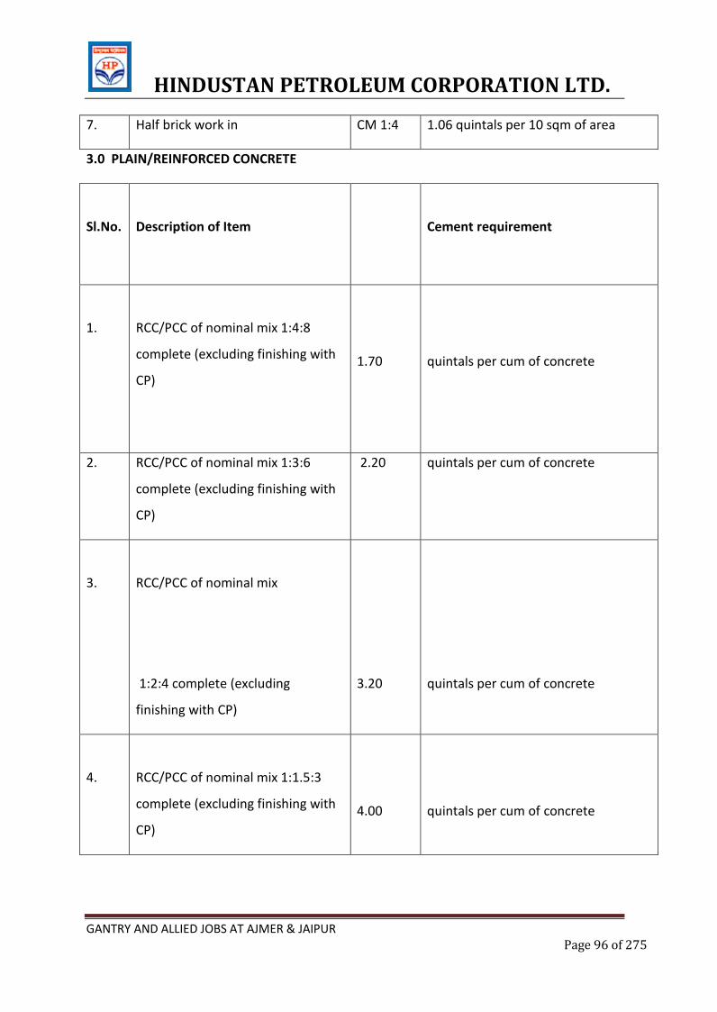
HINDUSTAN PETROLEUM CORPORATION LTD.
GANTRY AND ALLIED JOBS AT AJMER & JAIPUR Page 96 of 275
7. Half brick work in CM 1:4 1.06 quintals per 10 sqm of area
3.0 PLAIN/REINFORCED CONCRETE
Sl.No.
Description of Item
Cement requirement
1.
RCC/PCC of nominal mix 1:4:8
complete (excluding finishing with
CP)
1.70
quintals per cum of concrete
2. RCC/PCC of nominal mix 1:3:6
complete (excluding finishing with
CP)
2.20 quintals per cum of concrete
3.
RCC/PCC of nominal mix
1:2:4 complete (excluding
finishing with CP)
3.20
quintals per cum of concrete
4.
RCC/PCC of nominal mix 1:1.5:3
complete (excluding finishing with
CP)
4.00
quintals per cum of concrete
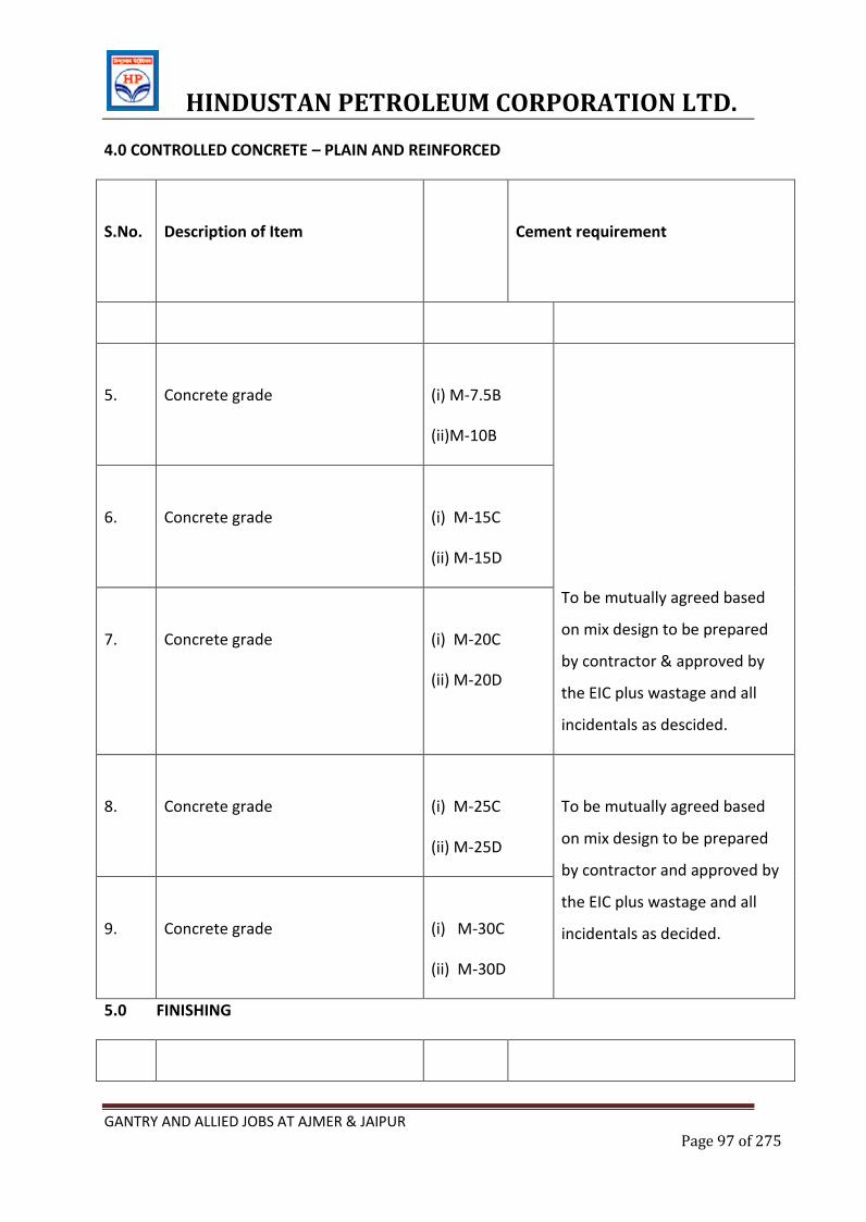
HINDUSTAN PETROLEUM CORPORATION LTD.
GANTRY AND ALLIED JOBS AT AJMER & JAIPUR Page 97 of 275
4.0 CONTROLLED CONCRETE – PLAIN AND REINFORCED
S.No.
Description of Item
Cement requirement
5.
Concrete grade
(i) M-7.5B
(ii)M-10B
To be mutually agreed based
on mix design to be prepared
by contractor & approved by
the EIC plus wastage and all
incidentals as descided.
6.
Concrete grade
(i) M-15C
(ii) M-15D
7.
Concrete grade
(i) M-20C
(ii) M-20D
8.
Concrete grade
(i) M-25C
(ii) M-25D
To be mutually agreed based
on mix design to be prepared
by contractor and approved by
the EIC plus wastage and all
incidentals as decided.
9.
Concrete grade
(i) M-30C
(ii) M-30D
5.0 FINISHING
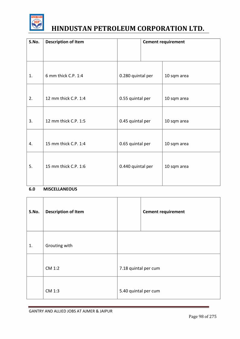
HINDUSTAN PETROLEUM CORPORATION LTD.
GANTRY AND ALLIED JOBS AT AJMER & JAIPUR Page 98 of 275
S.No. Description of Item
Cement requirement
1.
6 mm thick C.P. 1:4
0.280 quintal per
10 sqm area
2.
12 mm thick C.P. 1:4
0.55 quintal per
10 sqm area
3.
12 mm thick C.P. 1:5
0.45 quintal per
10 sqm area
4.
15 mm thick C.P. 1:4
0.65 quintal per
10 sqm area
5.
15 mm thick C.P. 1:6
0.440 quintal per
10 sqm area
6.0 MISCELLANEOUS
S.No.
Description of Item
Cement requirement
1.
Grouting with
CM 1:2
7.18 quintal per cum
CM 1:3
5.40 quintal per cum
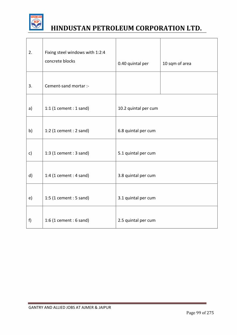
HINDUSTAN PETROLEUM CORPORATION LTD.
GANTRY AND ALLIED JOBS AT AJMER & JAIPUR Page 99 of 275
2.
Fixing steel windows with 1:2:4
concrete blocks
0.40 quintal per
10 sqm of area
3.
Cement-sand mortar :-
a)
1:1 (1 cement : 1 sand)
10.2 quintal per cum
b)
1:2 (1 cement : 2 sand)
6.8 quintal per cum
c)
1:3 (1 cement : 3 sand)
5.1 quintal per cum
d)
1:4 (1 cement : 4 sand)
3.8 quintal per cum
e)
1:5 (1 cement : 5 sand)
3.1 quintal per cum
f)
1:6 (1 cement : 6 sand)
2.5 quintal per cum
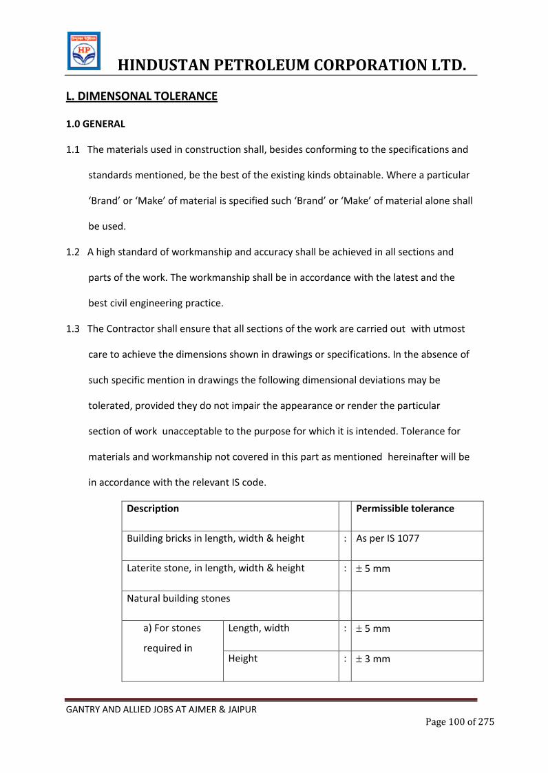
HINDUSTAN PETROLEUM CORPORATION LTD.
GANTRY AND ALLIED JOBS AT AJMER & JAIPUR Page 100 of 275
L. DIMENSONAL TOLERANCE
1.0 GENERAL
1.1 The materials used in construction shall, besides conforming to the specifications and
standards mentioned, be the best of the existing kinds obtainable. Where a particular
‘Brand’ or ‘Make’ of material is specified such ‘Brand’ or ‘Make’ of material alone shall
be used.
1.2 A high standard of workmanship and accuracy shall be achieved in all sections and
parts of the work. The workmanship shall be in accordance with the latest and the
best civil engineering practice.
1.3 The Contractor shall ensure that all sections of the work are carried out with utmost
care to achieve the dimensions shown in drawings or specifications. In the absence of
such specific mention in drawings the following dimensional deviations may be
tolerated, provided they do not impair the appearance or render the particular
section of work unacceptable to the purpose for which it is intended. Tolerance for
materials and workmanship not covered in this part as mentioned hereinafter will be
in accordance with the relevant IS code.
Description Permissible tolerance
Building bricks in length, width & height : As per IS 1077
Laterite stone, in length, width & height : 5 mm
Natural building stones
a) For stones
required in
Length, width : 5 mm
Height : 3 mm
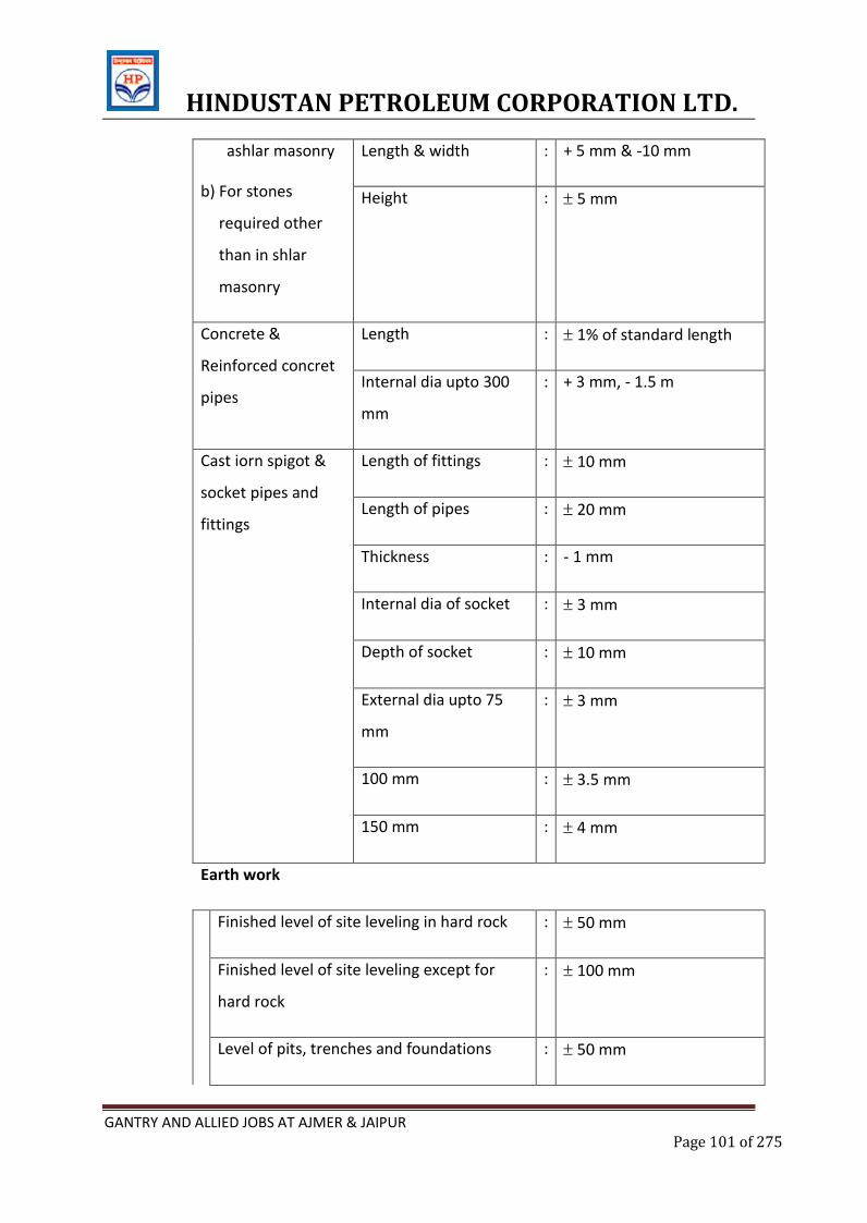
HINDUSTAN PETROLEUM CORPORATION LTD.
GANTRY AND ALLIED JOBS AT AJMER & JAIPUR Page 101 of 275
ashlar masonry
b) For stones
required other
than in shlar
masonry
Length & width : + 5 mm & -10 mm
Height : 5 mm
Concrete &
Reinforced concret
pipes
Length : 1% of standard length
Internal dia upto 300
mm
: + 3 mm, - 1.5 m
Cast iorn spigot &
socket pipes and
fittings
Length of fittings : 10 mm
Length of pipes : 20 mm
Thickness : - 1 mm
Internal dia of socket : 3 mm
Depth of socket : 10 mm
External dia upto 75
mm
: 3 mm
100 mm : 3.5 mm
150 mm : 4 mm
Earth work
Finished level of site leveling in hard rock : 50 mm
Finished level of site leveling except for
hard rock
: 100 mm
Level of pits, trenches and foundations : 50 mm
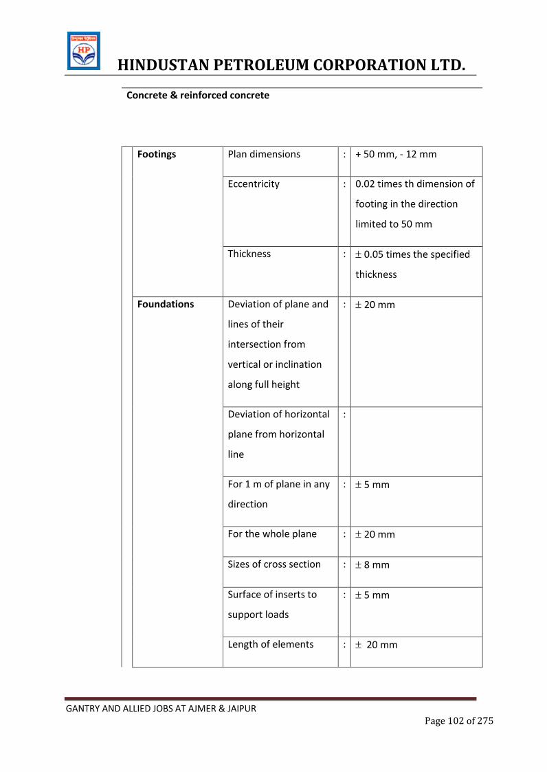
HINDUSTAN PETROLEUM CORPORATION LTD.
GANTRY AND ALLIED JOBS AT AJMER & JAIPUR Page 102 of 275
Concrete & reinforced concrete
Footings Plan dimensions : + 50 mm, - 12 mm
Eccentricity : 0.02 times th dimension of
footing in the direction
limited to 50 mm
Thickness : 0.05 times the specified
thickness
Foundations Deviation of plane and
lines of their
intersection from
vertical or inclination
along full height
: 20 mm
Deviation of horizontal
plane from horizontal
line
:
For 1 m of plane in any
direction
: 5 mm
For the whole plane : 20 mm
Sizes of cross section : 8 mm
Surface of inserts to
support loads
: 5 mm
Length of elements : 20 mm
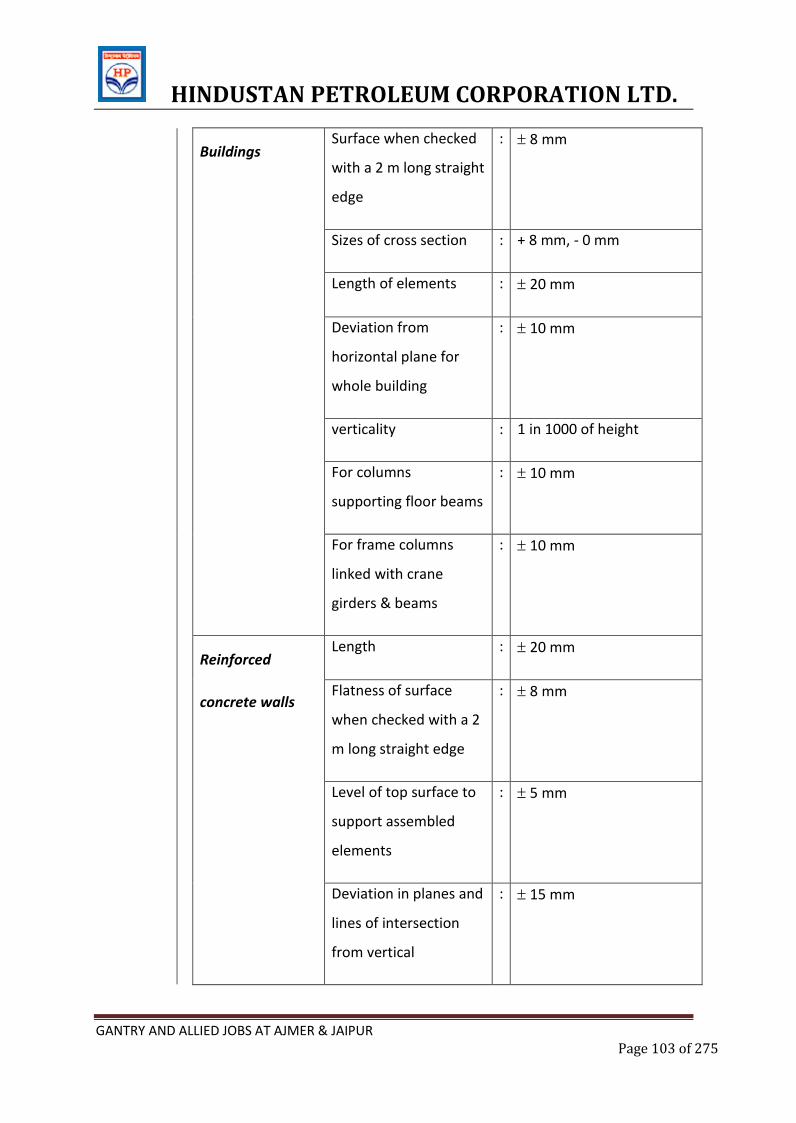
HINDUSTAN PETROLEUM CORPORATION LTD.
GANTRY AND ALLIED JOBS AT AJMER & JAIPUR Page 103 of 275
Buildings
Surface when checked
with a 2 m long straight
edge
: 8 mm
Sizes of cross section : + 8 mm, - 0 mm
Length of elements : 20 mm
Deviation from
horizontal plane for
whole building
: 10 mm
verticality : 1 in 1000 of height
For columns
supporting floor beams
: 10 mm
For frame columns
linked with crane
girders & beams
: 10 mm
Reinforced
concrete walls
Length : 20 mm
Flatness of surface
when checked with a 2
m long straight edge
: 8 mm
Level of top surface to
support assembled
elements
: 5 mm
Deviation in planes and
lines of intersection
from vertical
: 15 mm
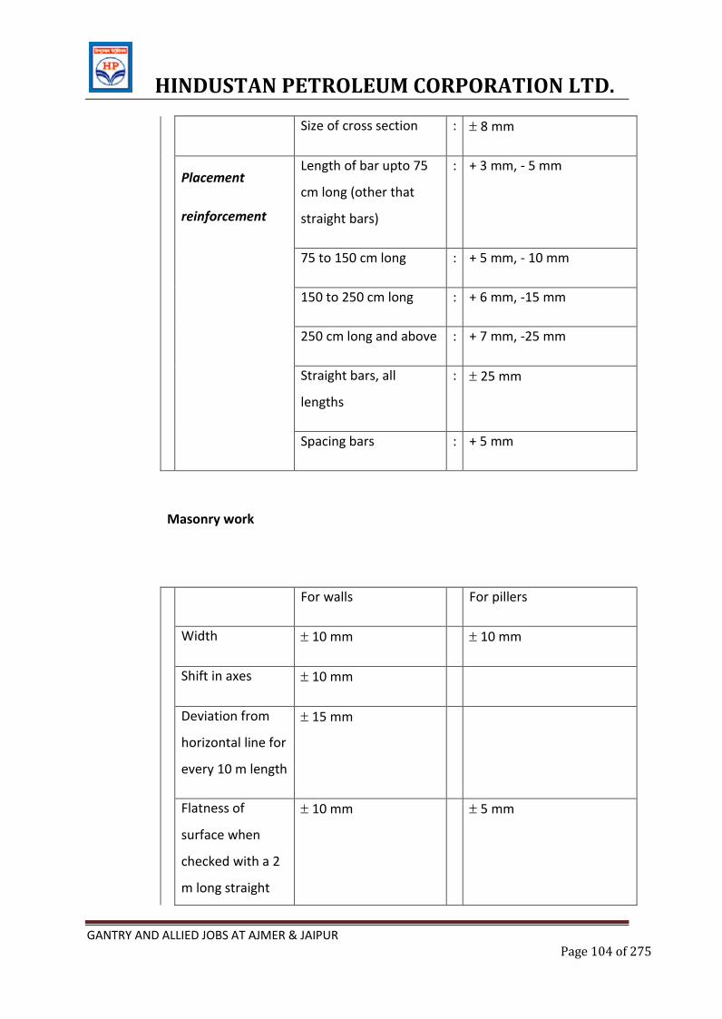
HINDUSTAN PETROLEUM CORPORATION LTD.
GANTRY AND ALLIED JOBS AT AJMER & JAIPUR Page 104 of 275
Size of cross section : 8 mm
Placement
reinforcement
Length of bar upto 75
cm long (other that
straight bars)
: + 3 mm, - 5 mm
75 to 150 cm long : + 5 mm, - 10 mm
150 to 250 cm long : + 6 mm, -15 mm
250 cm long and above : + 7 mm, -25 mm
Straight bars, all
lengths
: 25 mm
Spacing bars : + 5 mm
Masonry work
For walls For pillers
Width 10 mm 10 mm
Shift in axes 10 mm
Deviation from
horizontal line for
every 10 m length
15 mm
Flatness of
surface when
checked with a 2
m long straight
10 mm 5 mm
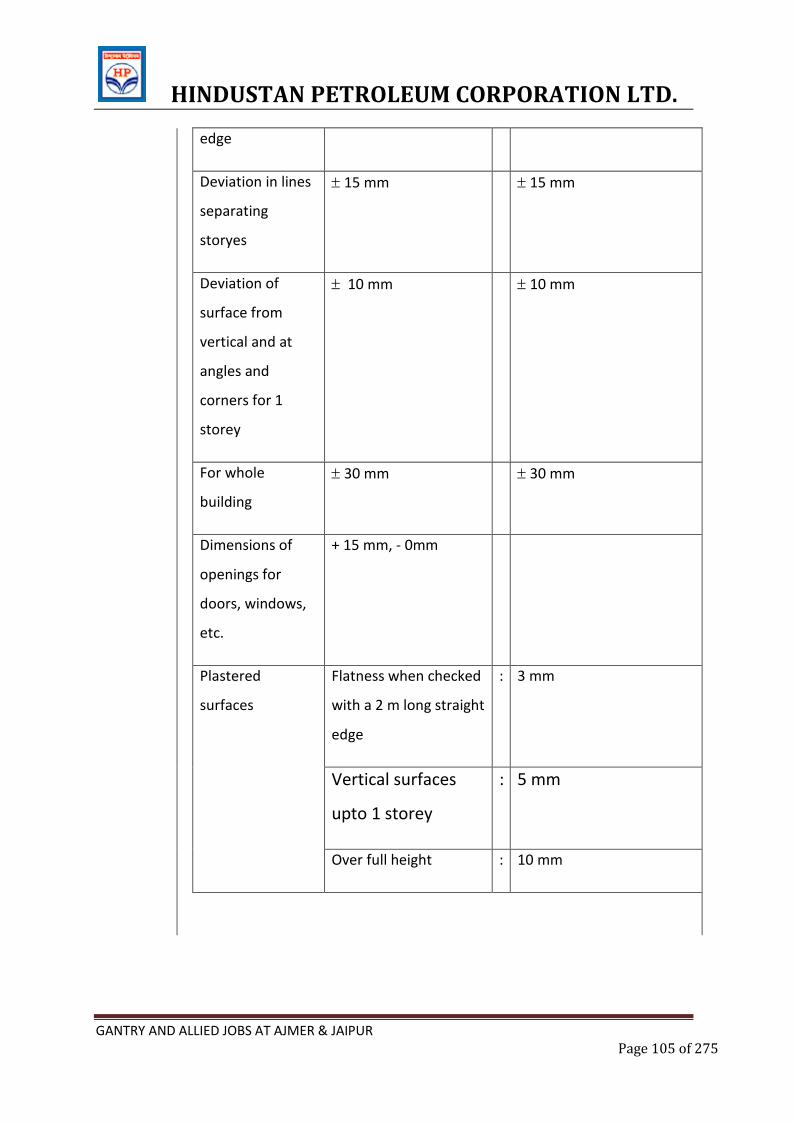
HINDUSTAN PETROLEUM CORPORATION LTD.
GANTRY AND ALLIED JOBS AT AJMER & JAIPUR Page 105 of 275
edge
Deviation in lines
separating
storyes
15 mm 15 mm
Deviation of
surface from
vertical and at
angles and
corners for 1
storey
10 mm 10 mm
For whole
building
30 mm 30 mm
Dimensions of
openings for
doors, windows,
etc.
+ 15 mm, - 0mm
Plastered
surfaces
Flatness when checked
with a 2 m long straight
edge
: 3 mm
Vertical surfaces
upto 1 storey
: 5 mm
Over full height : 10 mm
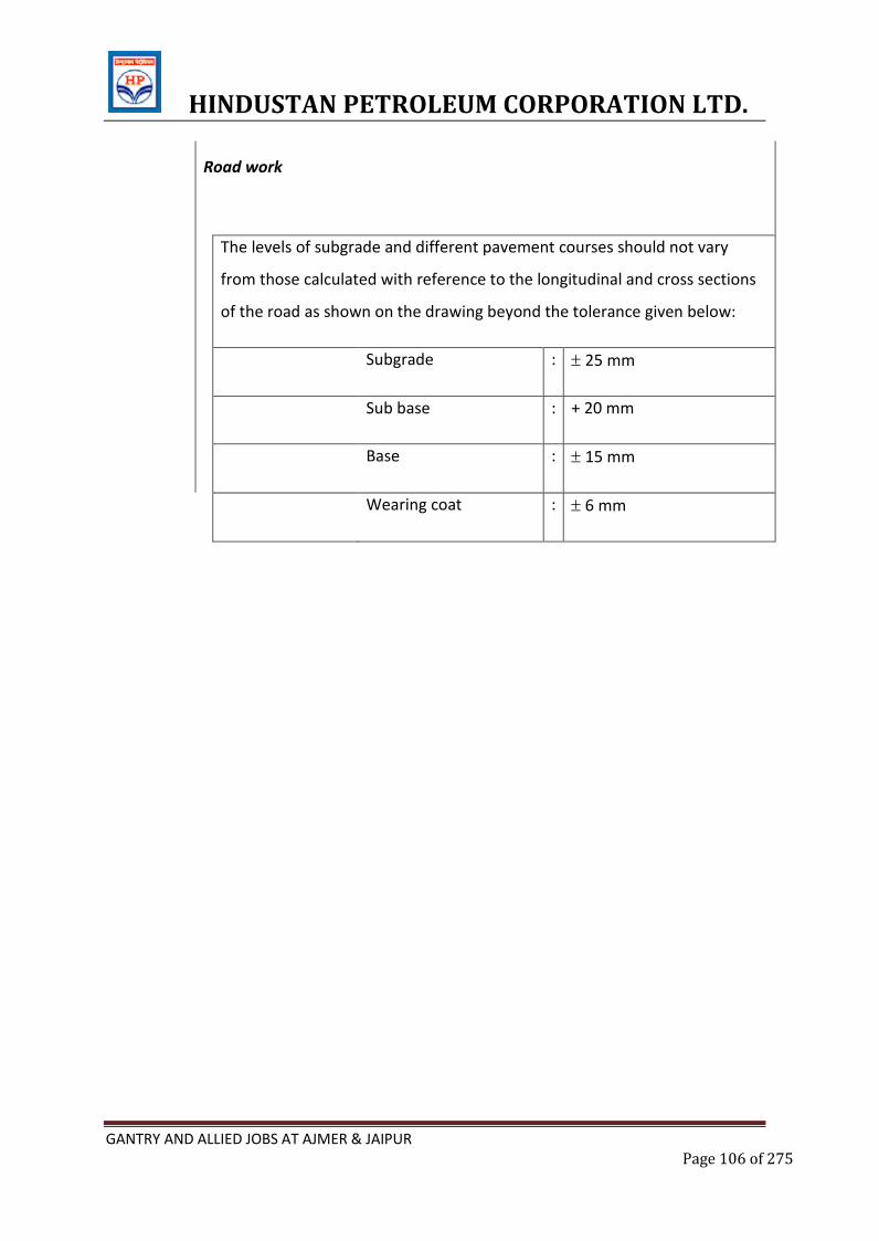
HINDUSTAN PETROLEUM CORPORATION LTD.
GANTRY AND ALLIED JOBS AT AJMER & JAIPUR Page 106 of 275
Road work
The levels of subgrade and different pavement courses should not vary
from those calculated with reference to the longitudinal and cross sections
of the road as shown on the drawing beyond the tolerance given below:
Subgrade : 25 mm
Sub base : + 20 mm
Base : 15 mm
Wearing coat : 6 mm
HINDUSTAN PETROLEUM CORPORATION LTD.
GANTRY AND ALLIED JOBS AT AJMER & JAIPUR Page 107 of 275
M.METHOD OF MEASUREMENT
1.0 GENERAL
1.1 The method of measurement of the various items of work shall be in accordance with
IS : 1200 (Part 1 to 28) – 1971 to 1993 / SP-27 .unless otherwise mentioned in this
part orin the schedule of items or in preamble or in the specification.
1.2 If there is any contradiction in meaning between any portion of this part and that of
IS : 1200 (Part 1 to 28) – 1971 to 1993, the stipulation of this part shall prevail.
1.3 The descriptions and explanations given herein have as much forces as though they
are incorporated into the description of the items themselves in the schedule of
items.
1.4 In case of dispute between the method of measurements mentioned here and the
respective bill of quantities, the method of measurement mentioned in the bill of
quantities shall prevail.
2.0 EARTH WORK & SAND FILLING
2.1.0 General
2.1.1 Each dimension upto 25 m shall be measured to nearest 0.01 m and to nearest 0.1
m for dimensions over 25 m. Areas shall be worked out to the nearest 0.01 m2 and
cubical contents to the nearest 0.01 m3.
2.1.2 Shoring and strutting shall not be measured separately unless otherwise specified.
2.1.3 Dewatering for earth work and sand filling work shall not be measured separately
unless otherwise specified.
2.1.4 For classification of soils, relevant clauses of Technical specification (workmanship
and other requirements) is to be followed.
2.2 Requirements for particular works
HINDUSTAN PETROLEUM CORPORATION LTD.
GANTRY AND ALLIED JOBS AT AJMER & JAIPUR Page 108 of 275
2.2.1.1 Site leveling
2.2.1.2 For site leveling levels shall be taken jointly before start & after completion of
work and the quantity computed based on the levels. Measurements shall be made only
for excavation and no separate measurement for filling shall be made except where
earth, borrowed from elsewhere for site levelling work, will be measured separately only
for that borrowed portion of earth.
2.2.1.3 In cases where it is not possible or convenient to take measurements from
excavated cuts or borrow pits, excavation shall be worked out from filling based on the
levels to be taken before and after completion of works. Deduction of 10 percent will be
made for voids, however for consolidated fills done through heavy mechanical means, the
deduction for voids shall be 5% in place of 10%.
2.2.1.4 In exceptional cases where the quantity is measured on the lorry measurement,
loose stacks, boxes or any other similar method with the approval of the EIC the deduction
for voids shall be 20 percent from the actual quantity.
2.2.2 Excavation
2.2.2.1 Before commencing excavation of foundations for buildings and structures, the
initial ground levels shall be jointly recorded. The depth of excavation and the calculation
of lift shall be based on this. Normally the initial ground level shall be considered as the
level of the site as handed over to the Contractor. In case excavation is planned and
approved to be taken up subsequent to terracing, the terrace level shall be treated as
initial ground level.
2.2.2.2 Excavation of foundations, trenches, basements, pits, etc., shall be measured to
the dimensions shown in the excavation plan, if any, or of the lowest concrete or masonry
course, as the case may be and the actual depth. Working space and slopes shall not be
measured.
2.2.2.3 Excavation of rock shall be measured from stacks of excavated rock with a
deduction of 50 per cent for voids or measured in the solid based on levels.
2.2.2.4 In case of following works, no measurement will be recorded for the excavation
beyond drawing/specification.
(a) In work which will be covered externally with damp proof covering.
HINDUSTAN PETROLEUM CORPORATION LTD.
GANTRY AND ALLIED JOBS AT AJMER & JAIPUR Page 109 of 275
(b) In work which requires formwork.
(c) In work which requires workmen to operate from the outside and for guniting and post
tensioned concrete, ground beams etc.
However, if there is a specific provision otherwise in the item/ specification/ preamble, for
authorised working, it shall be measured accordingly. This working space may be 60 cm
measured from the face of the structure at lowest level, unless otherwise mentioned.
2.2.2.5 Surface dressing
Trimming of natural ground, excavated surface and filled up area to remove vegetation
and/or small in equalities not exceeding 15 cm deep shall be described as surface dressing
and measured in square metres unless otherwise specified in the schedule of
items/preamble.
2.2.2.6 Lead
The distance for removal shall be measured over the shortest practicable route and not
necessarily the route actually taken.
The description of the item shall include loading and unloading.
For the purpose of the measurement of the lead, the area excavated shall be divided in
suitable block and for each block the distance from the centre of the block to the centre of
the placed earth pertaining to this block shall be taken as lead.
2.2.3 Back filling/filling
2.2.3.1 In foundations, trenches, basements, pits, etc. and in other like areas, the
measurements shall be the theoretical volume of the filling computed from drawings i.e.
the volume measured under excavation minus the volume occupied by the structure and
part filling if any, done otherwise.
2.2.3.2 In filling under floors the measurements shall be the theoretical volume as per
drawings after deducting the part filling if any, done otherwise.
2.2.3.3 In embankments, the work shall commence only after recording
2.2.3.4 jointly the initial ground levels and the measurements shall be made on the
HINDUSTAN PETROLEUM CORPORATION LTD.
GANTRY AND ALLIED JOBS AT AJMER & JAIPUR Page 110 of 275
basis of finished cross section and initial ground levels. Where controlled compaction by
mechanical compaction is done, 5% deduction for voids shall be made. In case controlled
compaction by mechanical means is not done then deduction for voids shall be 10%.
2.2.3.5 Filling/back filling shall not be measured separately for items of excavation,
where filling/back filling is a part of the composite item and as such is included in
excavation item itself.
3.0 CONCRETE (PLAIN & REINFORCED)
3.1 Concrete
3.1.1 Dimensions shall be measured to nearest 0.01 m except for the thickness of slab,
which will be to nearest 0.005 m. Areas shall be worked out to nearest 0.01 m2 and cubic
contents to nearest 0.01 m3.
3.1.2 The concrete shall be measured as per drawings except in the cases of approved
variations which will be measured separately.
No deductions shall be made for the following:
I. Ends of dissimilar materials such as beams, rafters, purlins, etc., upto 500 sqcm in
cress section.
II. Openings upto 0.1 sqm in area (In calculating area of an opening, the thickness of
any separate lintel or sill shall be included in the height. No extra labour for forming
such opening or voids shall be measured).
III. Volume occupied by reinforcement or other embedments such as anchors, inserts,
conduits or volume occupied by pipes, sheathing, etc., not exceeding 100 sqcm
each in cross sectional area or as specified.
IV. Small voids not exceeding 40 sqcm each in cross section.
V. Moulds, drip moulding, chamfer, splay, beds, grooves and rebates upto 10 cm in
width or 15 cm in girth.
3.1.3 Columns shall be measured from top of column base to underside of first floor slab
and from top of floor to underside of floor slab thereafter. Beams shall be measured from
face to face of columns and will include haunches. Depth of beam shall be measured form
HINDUSTAN PETROLEUM CORPORATION LTD.
GANTRY AND ALLIED JOBS AT AJMER & JAIPUR Page 111 of 275
bottom of slab and in case of inverted beams from top of slab. Chajjas and other
cantilevers shall be measured from face of projection. Where vertical fins are combined
with chajja, the later shall be measured clear between fins. In case chajja is not combined
with lintel, beam or slab, it shall be measured inclusive of bearing.
3.0 Reinforcement
3.1 Norms for steel consumption
The requirement of mild and high strength deformed bars for various works like
reinforcement, guard bars, fan hooks, etc. shall be calculated as mentioned below:
i) As per drawing including
a.) Authorized laps, bends, standard hooks and deviations etc.
b.) Spacer bars, chairs, hangers, supports, spacer blocks, dowels etc. are to be
considered for wastage only and not to be measured for payment purpose.
ii) Quantity up to 0.5% of (i) above towards unaccounted wastages, plus
i) Quantity up to 3% of (i) above towards cut pieces, which shall be pieces below
2m length. These cut pieces shall not be taken back even though steel has been
issued by the client/owner.
3.2 Reinforcements shall be measured in lengths to the nearest 0.01 m for various
diameters of bar and converted into weight in tonnes to the nearest kg on the basis of
standard weights as per IS: 1786 – 1986. No allowance shall be made in the weight for
rolling margin.
3.3 Authorised laps, standard hooks, bends shall be measured.
3.3.3.1 Spacer bars, chairs, hangers, supports, spacer blocks and unauthorised laps etc.
shall not be measured unless otherwise specified.
3.3.3.2 Dowels neither shown on the drawings nor instructed by the EIC but required
For construction facilities and/or sequence, shall not be measured for payment.
3.3.3.3 Modification of already embedded reinforcement, if required due to faulty
fabrication or placement, shall not be measured for payment.
3.3.3.4 The measurements of reinforcements (including authorised laps, hooks, bends
HINDUSTAN PETROLEUM CORPORATION LTD.
GANTRY AND ALLIED JOBS AT AJMER & JAIPUR Page 112 of 275
shall be taken only from Bar bending lists or from the drawings except in the cases of
approved variations which will be measured as per 4.2.2).
3.3.3.5 Hoop iron shall be fully described and measured in running metres unless
otherwise specified in the schedule of item.
3.3.3.6 Wire netting and fabric reinforcement shall be described ( including meshes and
wire/ strands) and measured in square metre, unless otherwise specified in the schedule of
item. Auhtorised laps shall be measured. Racking of circular cutting and waste shall be
included in the description of item.)
3.3.3.7 Binding wire for the reinforcement shall not be measured separately and shall
be included in the item of reinforcement.
4.0 Admixture
4.1 Admixture will be measured separately as specified or on the basis of the requirement
as approved by the EIC.
5.0 Formwork
5.1 Each dimension shall be measured to the nearest 0.01 m and area to the nearest 0.01
sq.m.
5.2 Formwork shall be measured as the actual surface in contact with concrete and paid in
sq.m. unless included in the rate for concrete in specific item of work.
5.3 All the measurements shall be computed from the drawings except in the cases of
approved variations which will be measured separately.
5.4 Formwork shall not be measured separately for precast concrete work, grouting and
damp proof course which shall be included in the concrete rates.
5.5No measurement for formwork in construction joints shall be made.
5.6 Openings upto 0.1 sqm shall be neglected, as if non-existant, for the purpose of
formwork measurement.
5.7No extra measurement or payment shall be made for making the form
HINDUSTAN PETROLEUM CORPORATION LTD.
GANTRY AND ALLIED JOBS AT AJMER & JAIPUR Page 113 of 275
work water proof or for supports, scaffolding, staging, centering, approaches, etc.
5.8 No measurement shall be taken for the formwork in pockets, openings, chambers,
chases, etc., in concrete if the cross sectional area is less than or equal to 0.1 sq.m. in each
case. If the cross section area of any opening exceeds 0.1 sq.m. the actual area of the
formwork shall be measured for payment.
6 Embedded Parts
6.1 These shall be measured on the basis of standard theoretical weight of the complete
insert according to the drawing/direction.
6.2 Embedded steel, which are the integral parts of the embedment according to drawing
and are required for anchoring the embedded parts in concrete shall be measured on
the basis of the theoretical standard weight. In case of anchor bolts the theoretical
weights of the nuts, lock nuts, check nuts and washers shall be added in the
measurement for payment.
6.3 All bye-works such as jigs, fixtures, templates and other arrangements which are not
integral parts of the embedded parts, but necessary to secure those (embedded parts) in
position shall not be measured for payment.
6.4 Anti-corrosive paint over the exposed surfaces and protection of the anchor bolts with
grease etc., shall not be measured for payment.
6.5 Modification works necessary to rectify the mistake of already placed embedded parts
shall not be measured.
7.0 Grouting
7.1 Grouting shall be measured in volume except in the cases of grouting by special cement
compound or epoxy compound which will be measured by number.
7.2 Measurement shall be computed from the drawings except in the cases of approved
variations which shall be measured separately and subsequently added to or deducted
from.
HINDUSTAN PETROLEUM CORPORATION LTD.
GANTRY AND ALLIED JOBS AT AJMER & JAIPUR Page 114 of 275
7.3Necessary formwork shall not be measured for payment.
8.0 MASONRY
8.1 Dimensions shall be measured to nearest 0.01 m, areas to nearest 0.01 sqm and cubic
contents to nearest 0.01 cum
8.2 No deduction shall me made for:
i) Ends of dissimilar materials such as joints, beams, posts, girders, trusses,
lintels, purlins, etc., upto 0.1sqm in section.
ii) Openings upto 0.1 sqm. In area.
iii) Wall plates, be plates, bearing of slab, etc., thickness not exceeding 10
cm and bearing not exceeding over full thickness of wall.
iv) Cement concrete blocks for hold fasts and the like.
v) Iron fixtures such as pipes, etc., upto 300 mm in diameter and hold fasts
for doors and windows.
8.3 Dressed stonework such as in sills, cornices, column caps, copings, etc., shall be
measured as the smallest rectangular block from which the finished stone can be worked.
8.4 Honey comb openings shall not be deducted from the area of honeycomb brickwork.
8.5 Brickwork of full brick width or more shall be measured in cum while of thickness half
brick or less shall be measured in sqm., unless otherwise specified.
8.6 Reinforcement for reinforced brick work shall be measured separately, unless
otherwise specified and no deduction for reinforcement shall be made from brickwork.
9.0 Deleted
10.0 PLASTERING & POINTING
10.1 All plastering and pointing shall be measured in sq.m. unless otherwise described.
Dimensions shall be measured to nearest 0.01 m and areas to 0.1 sq.m..
10.2 The methods of measurement including the deductions for openings etc. shall be
HINDUSTAN PETROLEUM CORPORATION LTD.
GANTRY AND ALLIED JOBS AT AJMER & JAIPUR Page 115 of 275
according to the relevant part of IS: 1200 (Part 1 to 28)
10.3 White washing, Colour washing, Painting and other finishes.
The method of measurement shall be according to the relevant part of IS 1200 (Part 13 &
15).
11.0 Deleted
12.0 Deleted
13.0 Road works
13.1 Dimensions shall be measured to nearest 0.01 m. Where the thickness is less than 20
cm, it shall be measured to nearest 0.005 m. Areas shall be calculated to nearest 0.01 sqm
and cubic contents to the nearest 0.01 cum.
13.2 Where thickness is measured, it shall be the minimum thickness after compaction.
13.3 Cement concrete bases and roads shall be measured either in sqm or in cum as
specified.
13.4 Unless otherwise specified, expansion and dummy joints shall be described and
measured separately and given in running meters stating the thickness and depth of the
joints.
HINDUSTAN PETROLEUM CORPORATION LTD.
GANTRY AND ALLIED JOBS AT AJMER & JAIPUR Page 116 of 275
N. SAFETY REQUIREMNTS FOR CONSTRUCTION WORKS
1.0 GENERAL
1.1 This specification deals with the subject matter of safety and protection to be observed
in the Road and bridge Construction. This shall be followed along with all related statutory
requirements/obligation including Governmental byelaws, codes, ordinance of local or
central authorities related to the construction work.
1.2 In case of complicated work like deep excavation, intricate shuttering and formwork,
excavation in loose soil and below water table, stacking of excavated earth etc., work plan
with necessary drawings and documents have to be prepared by the Contractor and got
approved by the EIC.
1.3 Necessary reference shall be made to the following Indian Standard Codes on safety
requirements for various type of work :
2.0 INDIAN STANDARD
4130 – 1991 Demolition of Buildings
3764 – 1992 Excavation Work
4014 – (P-II) – 1967 Scaffolding, Steel Tubular
3696 – (P-I & P-II) Scaffolds and Ladders
1987 to 1991
4138 – 1977 Working in Compressed Air
7293 – 1974 Working with Construction Machinery
8989 – 1978 Erection of Concrete Framed Structures
5916 – 1970 Safety code for construction involving use of hot bituminous
materials
HINDUSTAN PETROLEUM CORPORATION LTD.
GANTRY AND ALLIED JOBS AT AJMER & JAIPUR Page 117 of 275
3.0 EXCAVATIONS
3.1 No excavation or earth work below the foundation level of an adjoining building shall
be taken up unless adequate steps are taken to prevent damage to the existing structure or
fall of any part.
3.2 Every accessible part of an excavation, pit or opening in the ground into which there is
a danger of persons falling shall be suitably fenced with a barrier upto a height of one
metre suitably placed from the edge of the excavation as far as practicable.
3.3 No material or load shall be placed or stacked near the edge of the excavation or
opening in the ground. The excavated material shall not be placed within 1.5 m of the
trench or half of the depth of the trench whichever is more.
3.4 Cutting shall be done from top to bottom. No undercutting of sides of excavation shall
be allowed.
3.5 Materials shall not be dumped against existing walls or partition to a height that may
endanger the stability of the walls.
3.6 While withdrawing piled materials like loose earth, crushed stone, sand, etc. from the
stock piles, no over hanging shall be allowed to be formed in the existing dump.
3.7 No material on any of the sites of work shall be so stacked or placed as to cause
danger or inconvenience to any person or public or any other agency at work.
4.0 SCAFFOLDING, LADDERS & SHUTTERING
4.1 For all work that cannot be done from the ground level or from part of any permanent
structure or from other available means of support, soundly constructed scaffoldings of
adequate strength shall be used as a safe means of access to places of work.
4.2 All scaffolding shall be securely supported or suspended and wherever necessary be
properly braced to ensure stability.
HINDUSTAN PETROLEUM CORPORATION LTD.
GANTRY AND ALLIED JOBS AT AJMER & JAIPUR Page 118 of 275
4.3 All working platform and stages from which workers are liable to fall shall be of
adequate width depending on the type of work done and closely boarded and planked.
4.4 Every ladder shall be securely fixed at top and bottom. A ladder more than 5 m long
shall have a prop.
4.5 No portable single ladder shall be over 8 m in length.
4.6 Unfinished scaffolding which is under construction shall be prominently marked as
unsafe and any access points shall be closed.
4.7 Shuttering
The above remarks shall be applicable for this also. Shuttering, particularly for slabs, should
be treated as a scaffold. Unfinished shuttering should be marked as dangerous similarly the
finished form work should be adequately supported, care being taken to avoid trap door
effects.
5.0 SAFETY APPLIANCE
5.1 Those engaged in white washing and mixing or stacking of cement bags or any
materials which is injurious to the eyes, shall be provided with protective goggles.
5.2 The Contractor shall not employ men below the age of 18 and women on the work of
painting with products containing lead in any form. Whenever men above the age of 18
are employed on the work of lead painting the following precautions shall be taken :
a.) All necessary personnel safety equipment such as safety helmets, safety boots, safety
belts, leather gloves for welders, clear glass safety goggles etc., as considered adequate by
the EIC have to be kept available for the use of persons employed at the site of work and
maintained in condition suitable for immediate use and Contractor shall take steps to
ensure proper use of equipment by the workers.
b.) Sign boards 1 x 1.5 m in size with the following wording shall be erected atthe access to
these areas. “CONSTRUCTION AREA, HELMET REQUIRED BEYOND THIS POINT”.
HINDUSTAN PETROLEUM CORPORATION LTD.
GANTRY AND ALLIED JOBS AT AJMER & JAIPUR Page 119 of 275
Arrangement for rendering prompt and adequate first aid to the injured persons shall be
maintained at every work site under the guidance of a medical officer-in-charge of the
project. Depending upon the magnitude of the work the availability of an ambulance at a
very short notice (a telephone call) shall be ensured.
First-aid arrangements commensurate with the degree of hazard and with the number of
workers employed shall be maintained in a readily accessible place throughout the
working hours. At least one experienced first-air attendant with his distinguishing badge
shall be available on each shift to take care of injured persons. Arrangements shall be
made for calling the medical officer, when such a need may arise. It is recommended that
foreman/assistant foreman/supervisor/permanent workmen who are normally present at
each working phase in each shift are given adequate training on first-aid methods to avoid
employment of a separate attendant.
6.0 MISCELLANEOUS
6.1 The Contractor shall provide necessary fencing and lights to protect the public from
accident.
6.2 To ensure effective enforcement of the rules and regulations relating to safety
precautions, the arrangements made by the Contractor shall be open to inspection by the
EIC and Owner.
6.3 All sources of ignition shall be prohibited in areas where flammable liquids are stored,
handled and processed. Suitable warning and ‘NO SMOKING’ signs shall be posted in all
such places. Receptacles containing flammable liquids shall be stacked in such a manner as
to permit free passage of air between them.
6.4 All combustible materials shall be continuously removed from such areas where
Flammable liquids are stored, handled and processed. All spills of flammable liquids shall
be cleared up immediately. Containers of flammable liquids shall be tightly capped.
7.0 REPORTING OF ACCIDENT
HINDUSTAN PETROLEUM CORPORATION LTD.
GANTRY AND ALLIED JOBS AT AJMER & JAIPUR Page 120 of 275
7.1 All accidents, major or minor must be reported immediately. The Contractor, will
provide first aid to the injured person immediately and the injured person shall report to
the first aid station along with the ‘INJURED ON WORK’ form duly filled in quintuplicate and
submit to the Medical Officer of the First Aid Station”.
7.2 Serious Injury
7.2 In case of serious injury, the following procedure shall be adopted by the Contractor:
a) Provide First Aid at his own First Aid Station.
b) Take the injured person to the Hospital along with the “INJURED ON WORK” form duly
filled in.
c) Reporting the accident to the Owner/EIC by the Contractor.
7.3 Fatal Accident
Fatal accident must be reported immediately to the EIC/Owner as well as to the Police.
8.0 PENALTY
Failure to observe the Safety Rules will make the Contractor liable to penalty by way of
suspension of work, fine and termination of contract.
HINDUSTAN PETROLEUM CORPORATION LTD.
GANTRY AND ALLIED JOBS AT AJMER & JAIPUR Page 121 of 275
E.2. SPECIFICATIONS FOR
ALUMINUM WORK
HINDUSTAN PETROLEUM CORPORATION LTD.
GANTRY AND ALLIED JOBS AT AJMER & JAIPUR Page 122 of 275
ALUMINIUM DOOR, VENTILATORS & WINDOWS WORKS
1.0 SCOPE
The work in general shall consist of fabrication, supplying, erecting and installing of all
aluminum doors, windows, ventilators, louvers etc. as stipulated here or elsewhere in
these specifications with all materials complete including labour and equipment.
2.0 GENERAL:
2.1 The contractor shall submit 3 copies of shop drawing covering all types of work under
this specification before manufacture. The drawing shall show all dimensions,
member designations details of construction, installation, relating to adjoining and
related work etc The work shall be carried out as per approved shop drawings relevant
detailed approved shop drawings.
2.2 The contractor shall submit 6 copies of shop drawings covering all type/details of work
and generally shown in architectural drawings and envisaged under these specifications
before manufacture. The drawings shall show all dimensions details of constructions,
installation of fixtures and relation to adjoining and related works. No fabrication work
shall be undertaken prior to obtaining approval of the shop drawings from the EIC. The
Contractor shall intimate at the time of tendering the type of sections he proposes to
use on the works.
3.0 CODES AND STANDARDS
3.1 All applicable standards, acts and codes of practice referred to shall be the latest
editions including all applicable official amendments and revisions. A complete set of
all these documents shall generally be available at site, with the Contractor.
3.2 In case of conflict between this specification and those (IS Standards, Codes etc.)
referred to in clause 3.03.00 the former shall prevail.
3.3 Some of the applicable Indian standards, Codes, etc. are referred to here
below:
IS : 733 1983 Specifications for wrought aluminum and
aluminum alloy bars, rods, sections (for
HINDUSTAN PETROLEUM CORPORATION LTD.
GANTRY AND ALLIED JOBS AT AJMER & JAIPUR Page 123 of 275
general engineering purposes)
IS : 1081 1960 Code of practice for fixing and glazing of
metal (steel and aluminum) doors, windows
& ventilators
IS : 1868 1996 Specifications for anodised coatings on
aluminum and its alloys
4.0 MATERIALS
4.1 Aluminum alloy for extruded sections for the above work shall correspond to I.S 733
(extruded sections shall conform to IS Designation HE 9 – WP. Hollow sections shall
conform to IS Designation HV9-WP) and shall be anodised before incorporating in the
work. The door, window, ventilator, glazing framework, beadings, hinges, pegstays, stiles,
mullions, beadings, transoms and handles etc shall be of aluminum anodised section as
shown in detailed approved drawings. All aluminum sections shall be from approved
reputed manufacturer.
4.2 The contractors can also propose nearest alternative section they manufacture/possess
without changing the elevation, structural stability and functional requirement.EIC reserves
the right to accept the alternative section or otherwise. The sections shall be structurally
suitable to withstand all the loads; the members have to sustain.
4.3Counter sunk screws, nuts, bolts, washers, rivers and other miscellaneous fastenings
devices shall be of approved brass cadmium plated or stainless as specified in the approved
drawing. Each door leaf shall be prepared to receive glazed panel of required thickness.
HINDUSTAN PETROLEUM CORPORATION LTD.
GANTRY AND ALLIED JOBS AT AJMER & JAIPUR Page 124 of 275
4.4Glazing shall be done with neoprene dry set glazing gasket (of best quality and approved
make) with snap – in – beveled white anodised matt finish aluminum metal glazing stops
inside and outside,
5.0 FABRICATION:
5.1 Doors
5.1.1 The frames shall be manufactured square and flat, the corners of the frame being
fabricated to true right angle. All the fixed, sliding and opening frames shall be constructed
of sections, which have been to length, mitred, welded and mechanically fixed at the
corners.
5.1.2 Where hollow sections are used with welded joints, argon-arc welding or flash butt
welding shall be employed (Gas welding or brazing not to be done). In case welded joints
are used, anodising shall be done after fabrication as a whole. All welding shall be on
unexposed sides in order to prevent pitting / discoloration of other surface imperfections
after fixing etc.
5.1.3 Necessary allowance shall be made while manufacturing the aluminum door
entrances, wall spans and glazing for receiving plaster. Field fabrication of frames shall be
done only if permitted by EIC.
5.1.4 A thick layer of clear transparent lacquer based on methacrylates or cellulose
butyrate shall be applied on the finished sections of the aluminum work by the contractor
to protect the surfaces from wet cement, lime, dirt, dust etc during the construction
activities. The size for door, window or ventilator frames shall not vary by more than (+/-)
1.5 mm.
5.1.5 All aluminum surfaces in contact with masonry or concrete shall be given a thick coat
HINDUSTAN PETROLEUM CORPORATION LTD.
GANTRY AND ALLIED JOBS AT AJMER & JAIPUR Page 125 of 275
of bitumastic paint. After fabrication, aluminum sections shall be protected from
construction hazards that may damage their appearance or finish. All exposed surfaces of
aluminum door entrance shall be protected by masking tape during transshipment and
erection
5.2 Windows and Ventilators
5.2.1 The frames shall be manufactured square and flat. The corners of the frames shall be
fabricated to true right angles. All the fixed, sliding, openable frames shall be constructed
from sections, which have been cut to length, mitred and mechanically jointed or welded at
the corners.
5.2.2 Where hollow sections are used with welded joints, argon are welding or flash butt
welding shall be employed (Gas welding or brazing not to be done). Sub-dividing bars of
units shall be tennoned and rivetted into the frames. In case welded joints are used, all
welding shall be on unexposed sides in order to prevent pitting, discoloration and other
surface imperfections after finishing.
5.2.3 The dimensions shown in the drawing are overall heights and widths to the outside of
frames of aluminum windows. The side-hung shutters shall have projected friction type
hinges of aluminum alloy. Concealed projected hinges having structural stability and of
good quality will also be considered only after the inspection of the sample submitted by
the Contractor
5.2.4 The necessary pegstays, handles, window fasteners etc shall be of aluminum. The
handle shall be mounted on a handle plate riveted to the opening frame. The pegstays
HINDUSTAN PETROLEUM CORPORATION LTD.
GANTRY AND ALLIED JOBS AT AJMER & JAIPUR Page 126 of 275
shall be 300 mm. Long or as required complete with peg and locking bracket and shall have
holes for keeping the shutter open in three different positions. Field fabrication of
frames shall be done only if permitted by EIC.
5.2.5 The complete fabricated assembly shall be anodised in approved satin finish with
minimum film thickness of 0.015 mm for the entire surface. A thick layer of clear
transparent lacquer based on methacrylate or cellulose butyrate shall be applied on the
finished sections of the aluminum windows etc. by the supplier to protect the surfaces from
wet cement, lime, dirt, dust etc during the installation. The lacquer coating shall be
removed after installation is complete, if approved by the EIC and all sections of the
windows shall be protected by PVC film covering.
6.0 HARDWARE:
6.1 All sections and hardware shall have anodic film and cover a minimum thickness of
0.015 mm.
6.2 All doors shall have offset pivots; double action (1800 minimum swing) floor springs
with oil check boxes of approved manufacture. All doors shall have 4 lever concealed brass
body mortise lock without handles as per manufactures design, with concealed flush C.P.
brass tower bolts provided at suitable locations. All doors shall have push plates of
design shown in the approved drawing as described in the schedule of quantities. All
entrances shall be without thresholds.
6.3 All cutouts, recess, mortising or milling and operations required for fixing the hardware
shall be accurately made reinforced with pacing plate as required to ensure adequate
strength of the connection.
HINDUSTAN PETROLEUM CORPORATION LTD.
GANTRY AND ALLIED JOBS AT AJMER & JAIPUR Page 127 of 275
6.4 All the hardware accessories shall be of best-approved type and of anodised finish
same as of rate frames and other sections. Each lock shall be supplied with two stainless
steel keys and each key shall be with number stamped thereon according to the number on
doors so installed.
6.5 All hardware shall be free from defects which may affect the appearance and
serviceability. All hardware shall be fixed after obtaining the prior approval of the
Engineer-in-charge.
6.6 Approved samples of hardware shall be kept in the custody of the Engineer-in-charge.
Working and moving parts of lock sets shall be accurately fitted to smooth, close bearings
and shall be free from rattle.
6.7 The floor springs shall be of heavy-duty type and should allow door operation smoothly.
6.8 The contractor shall furnish a guarantee for all finishing and quality of hardware
covered under this section and which shall remain free from defects of any kind, either
materials and / or workmanship for a period of one year (unless otherwise specified) from
the date of competition/handling over of work.
6.9 The contractor shall repair of replace any and all defective work and damage caused, at
any time or times during that period within 3 days from the written notice. This shall be
done without any extra cost to the Owner.
7.0 FIXING
7.1 The frames shall be accurately fixed in the flooring/brick masonry or R.C.C works. The
fixing of the frame shall be done with cadmium plated brass counter sunk screws driven on
to the teak wood rough ground, or fixed to the wall with hodfasts as directed by the EIC,
and as shown in approved drawings.
HINDUSTAN PETROLEUM CORPORATION LTD.
GANTRY AND ALLIED JOBS AT AJMER & JAIPUR Page 128 of 275
7.2 All aluminum works shall be fixed in position as per relevant Indian Standard
Specifications and code of practice for fixing and glazing of aluminum work. Joints between
metal and masonry shall be neatly painted with matching cement and excess materials shall
be removed.
7.3 Fixing of aluminum door entrances, hardware etc shall be done in best workmanship
like manner true to line, level, plane, plumb etc and all as directed by the EIC. Breaking of
floor for providing floor springs and restoration of the floor finishes to the original
specification and finishes and minor additions and alternations to the openings shall be
deemed to have been included in the quoted rates.
7.4 All aluminum windows shall be fixed in position as per IS 1081. All joints between metal
and masonry / rough ground wooden frame shall be fully caulked with music or
ploysulphidc compound in order to ensure watertight joints. Joints shall be neatly painted
with matching cement and excess materials shall be removed. Hardware shall be fixed in
workman like manner all as directed by the EIC.
8.0 HANDLING AND STORAGE
All aluminum doors, windows, etc. shall be packed and crated properly before dispatch, to
ensure that there will be no damage to the fabricated materials. Loading into wagons and
trucks shall be done with all care to ensure safe arrival of materials at site in undamaged
condition. All doors, windows etc. shall be stored under cover in a way to prevent damage
or distortion.
9.0 ACCEPTANCE CRITERIA
9.1 For Fabricated Items
A. Overall dimension shall be within + 1.5 mm of the size
B. Mullions, transoms etc. shall be in one length and permissible deviations from
straightness shall be limited to n 1.5 mm from the axis of the member.
C. Door and window shutters shall operate without jamming. The
clearance at head and jamb for door shutters shall not exceed 1.5 mm. For double
leaf doors, the gap at the meeting of stiles shall not be more than 1.5mm.
HINDUSTAN PETROLEUM CORPORATION LTD.
GANTRY AND ALLIED JOBS AT AJMER & JAIPUR Page 129 of 275
D. Door leaves shall be undercut wherever required.
E. Doors, windows, frames etc. shall be on a true plane, free from warp or
buckle.
F. All welds shall be dressed flush on exposed and contact surfaces.
G. Correctness of location and smoothness of operations of all shop installed hardware
and fixtures.
H. Provision for hardware and fixtures to be installed at site.
I. Glazing clips, fixing devices etc. shall be supplied in adequate numbers
J. Shop coats shall be properly applied.
K. Glazing beads shall be cut with mitered corners.
9.2. For Installed Items
a. Installations shall be at correct location, elevation and in general, on a true vertical
plane.
b.Fixing details shall be strictly as shown on drawings.
c.Assembly of composite units shall be strictly as per the drawings with mastic caulking at
transoms and mullions, gaskets, weather strips etc. complete.
d.All frames on external walls shall be mastic caulked to prevent leakage through joint
between frames and masonry.
e. All openable sections shall operate smoothly without jamming.
f. Locks, fasteners etc. shall engage positively. Key shall be non- interchangeable.
g. Cutting to concrete or masonry shall be made good and all abrasions to shop paint
shall be touched up with paint of same quality as shop paint.
GLASS FOR DOORS, WINDOWS AND VENTILATORS
1.0 SCOPE
1.1 The work in general shall consist of supplying and fixing all glass and glazing including all
clips, putty, mastic cement etc. wherever required as shown on drawings.
2.0 CODES AND STANDARDS
HINDUSTAN PETROLEUM CORPORATION LTD.
GANTRY AND ALLIED JOBS AT AJMER & JAIPUR Page 130 of 275
2.1 All applicable standards, acts and codes of practice referred to shall be the latest
editions including all applicable official amendments and revisions. A complete set of all
these documents shall generally be available at site, with the Contractor.
2.2 In case of conflict between this specification and those (IS Standards, Codes etc.)
referred to in clause 2.03.00 the former shall prevail.
3.2 Some of the applicable Indian standards, Codes, etc. are referred to here
below:
IS : 419 1967 Putty for use on window frames
IS : 1081 1960 Code of practice for fixing and glazing metal
(steel & aluminium) doors, windows and
ventilators
IS : 2835 1987 Flat transparent sheet glass
IS : 3548 1988 Code of practice for glazing in building
IS : 5437 1994 Figured rolled and wired glass
IS : 14900 2000 Specification for transparent float glass
3.0 MATERIALS
3.1 The Contractor shall supply and install all glass and glazing as required for various doors,
windows, ventilators, and fixed louvers, and partitions, unless otherwise stated, from
approved manufacture having uniform refractive index and free from flaws, specks and
bubbles. The glass shall be brought to site in the original packing from the manufacturer
and cut to size at site. The cut edges shall be straight and free from chips, spall or any
other damages.
3.2 The glass shall be plain float glass from approved manufacture, as specified and it shall
be free from bubbles, flaws specs, waves, air holes, distortion, scratches or other defects.
The glasses in bulk quantities shall be brought to site in Makers original packing and
HINDUSTAN PETROLEUM CORPORATION LTD.
GANTRY AND ALLIED JOBS AT AJMER & JAIPUR Page 131 of 275
Makers guarantee shall be produced if called for by the EIC. The glass shall be of required
thickness as mentioned in the items of schedule of quantities and / or drawing or as
directed by the EIC. The contractor shall submit the sample of the glass which he
proposes to use on the work and only such approved quality of glass shall be used in the
works. The glass brought to site shall be protected against damages. Wherever frosted
(obscure) glass is mentioned in the item of schedule of quantities and / or shown in
drawings, the glass shall be of sand blown pattern and shall also be got approved by the
Engineer-in-Charge.
3.3 After the inspection is over and permitted by the EIC, glass panes shall be cleaned off
any labels paints smears and spots and shall be washed from both the sides and all glazing
left elar, perfect and free from rattling. The contractor shall provide all the scaffolding tools
and plants for fixing the glass panes at his own cost.
3.4 Glare reducing (tinted) or heat absorbing glass shall be “Calores” of Hindustan
Pilkington or approved equivalent and special care shall be taken to grind smooth and
round off the edges before fixing.
3.5 Clear glass shall be flat drawn and shall be at least 4 mm thick,
3.6 Wired glass shall be 6 mm thick rolled glass with centrally embedded 24 G wire mesh of
Georgian type. This may be of clear or coloured glass, as required by Engineer and shall
conform to lS:5437.
3.7 Deleted
3.8 Deleted
3.9 In general, the putty shall conform to lS:419 and be of best quality from approved
manufacturer. it shall be brought to site in the manufacturer’s original packing. Quick
setting putty shall be used for windows and sashes except when glare reducing glass is
used where it shall be of non-setting type.
3.10 Neoprene gaskets with snap-fit glazing shall be fixed as per manufacturer’s
HINDUSTAN PETROLEUM CORPORATION LTD.
GANTRY AND ALLIED JOBS AT AJMER & JAIPUR Page 132 of 275
instruction and shall fit firmly against the glass to give a leak proof Installation.
4.0 FIXING
4.1 The glass shall be cut to the required sizes of panels where it is to be fitted and it shall
be so cut that it fits properly in the frames without rattling. Pre-measurement of each
panel prior to the cutting of glass is essential.
4.2 The beading shall then be fixed to glass panes and screwed at close intervals not more
than 10 cm. from each corner and the intermediate not more than 20 cm. apart. When
glass panes are fixed with wooden beadings having mitred joints or aluminium beading thin
layer of glazier putty shall be applied covering the area in contact between the glass and
sashbars and beadings. In case of louvers, all the exposed edges of the glass shall be
ground properly
4.3 All glazing clips, bolts, nuts, putty, mastic cement, etc. as required shall be supplied by
the Contractor.
4.4 All glass shall be thoroughly cleaned before placing in positions. Each glass pane shall be
held in place by special glazing clips of approved type. As specified in relevant l.S. Codes,
four glazing clips shall be provided per glass pane, except for large panes where six or more
clips shall be used as per Engineer’s instructions. All holes that may be necessary for
holding the clips, glazing beads and all other attachments shall be drilled by the Contractor.
4.5Glass pane shall be set without springing, and shall be bedded in putty and back putted,
except where mouldings or gaskets are specified. Putty, mastic cement etc. shall be
smoothly finished to a true even line. Obscure and figured glass shall be set with smooth.
side out.
4.6 After completion of glazing work, the Contractor shall remove all dirt, stains, putty etc.
clean the glass panes and leave the work in perfectly acceptable condition. All broken,
cracked or dameged glass shall be replaced by new ones
4.7 The beading shall be of teak wood of superior quality timber in case of teak wood doors
and windows and / or required sizes mentioned in the items of schedule of quantities and /
HINDUSTAN PETROLEUM CORPORATION LTD.
GANTRY AND ALLIED JOBS AT AJMER & JAIPUR Page 133 of 275
or shown in drawing. In case of steel doors and windows the beading shall be anodised
aluminium beading of channel section as per size mentioned in the item and / or shown in
the drawing. The junction of the beadings shall be mitre jointed.
5.0 ACCEPTANCE CRITERIA
a) All installations shall be free from cracked, broken or damaged glass. Edges of large
panes of thicker glass and heat absorbing glass shall be inspected carefully for chipped,
cracked or un ground edges.
b) Glazing shall be carefully done to avoid direct contact with metal frames.
c) All glass shall be embedded in mastic or fixed by neoprene gaskets to give a leak-proof
installation.
d) At completion, the panes shall be free from dirt, stains, excess putty etc. and to
complete satisfaction of the Engineer.
HINDUSTAN PETROLEUM CORPORATION LTD.
GANTRY AND ALLIED JOBS AT AJMER & JAIPUR Page 134 of 275
E.3 GENERAL SPECIFICATION
FOR FABRICATION OF PIPELINE
HINDUSTAN PETROLEUM CORPORATION LTD.
GANTRY AND ALLIED JOBS AT AJMER & JAIPUR Page 135 of 275
WELDING SPECIFICATION FOR THE FABRICATION OF PIPING
(Above Ground Portion)
1. GENERAL
This specification shall be followed for the fabrication of all types of welded joints of MS /
carbon steel and alloy steel piping system within the battery limits of the plant.
The welded pipe joints shall include the following:
i. All pipe joints of the longitudinal and circumferential butt welded and socket welded
types. Attachments of forgings, flanges and other supports to pipes. Welded manifold
headers and other sub-assemblies Welded branch connections with or without
reinforcing pads. Joints in welded / fabricated piping components. The attachments of
smaller connections for vents, drain drips and other instrument tappings.
ii. Any approval granted by the Engineer-in-charge or Owner’s inspector, shall not relieve
the Contractor of his responsibilities and guarantee.
iii. This specification shall not be applicable for welding of pipelines for transportation of
liquid petroleum and other similar products.
2. APPLICATION CODES & STANDARDS:
All welding work, equipments for welding, heat treatment, other auxiliary functions and the
welding personnel shall meet the requirements of the latest editions of the following
expected standards and procedures unless otherwise specified in the Welding specification
chart and the technical notes attached. In the case of conflicting requirements, the
requirements mentioned in welding specification chart / Technical Notes shall be applicable.
i. Chemical Plant and Petroleum Refinery Piping - ANSI:B31.3
ii. The Indian Boiler Regulations - I.B.R.
iii. Relevant code of fabrication shall be followed for the welding procedures.
iv. Welding and Brazing Qualifications ASME Sec IX.
v. Non destructive examination ASME Sec. V
vi. Material Specifications : welding rods, Electrodes and filler metals ASME Sec II Part C
HINDUSTAN PETROLEUM CORPORATION LTD.
GANTRY AND ALLIED JOBS AT AJMER & JAIPUR Page 136 of 275
In the event of any differences due to the additional requirements mentioned in this
specification, over and above those obligatory as per codes, this specification shall be
binding.
3. BASE METAL:
I. In general, use of carbon steel, alloy steel and stainless steel are envisaged. The details of
the material specifications are given in the welding specification chart.
II. The contractor shall provide the manufacturer’s test certificates for every heat of the
materials supplied by him.
4. WELDING CONSUMABLES
i. The contractor shall provide, at his own expense, all the welding consumables
necessary for the execution of the job such as electrodes, filler wires, oxygen,
acetylene, argon etc, and these should bear the approval of the Engineer-in-charge.
ii. The welding electrodes and filler wires supplied by the Contractor shall conform to the
class specified in the welding specifications chart. The materials shall be of the make
approved by the Engineer-in-charge.
iii. Electrode qualification test records should be submitted as per the Exhibit –A
(attached) in respect of the electrodes tested by the Contractor, for obtaining the
approval of the engineer-in-charge.
iv. The contractor shall submit batch test certificates, from the electrode manufacturers,
giving details of physical and chemical tests carried out by them, for each batch of
electrode to be used.
v. All electrodes shall be purchased in sealed containers and stores properly to prevent
deterioration. The electrodes removed from the containers shall be kept in holding
ovens at temperatures recommended by the electrode manufacturer. ‘Out of the oven
time’ on electrodes, before they are consumed shall not exceed the limits
recommended by the electrode manufacturer. The electrodes shall be handled with
care to avoid any damage to the flux covering.
HINDUSTAN PETROLEUM CORPORATION LTD.
GANTRY AND ALLIED JOBS AT AJMER & JAIPUR Page 137 of 275
vi. All low hydrogen tupe of electrodes shall be rebarked at 3500 C for 1 hour minimum
and stored in ovens kept at 80-1000C before use. Recommendations of the electrode
manufacturer shall be followed if available.
vii. The electrodes, filler wires and flux used shall be free from rust, oil, grease, earth and
other foreign matter which affect the quality of welding.
viii. Tungsten electrodes used shall conform to SPA 5.12 specification.
5. SHIELDING & PURGING GAS :
Argon gas used in GTA welding for shielding purpose shall be 99.995% pure. The purity of the
gas shall be certified by the manufacturer. The rate of flow shielding purpose shall be
established through procedure qualification tests. Normally this rate may be 12-20 CFH.
i. Argon gas with a purity level of 99.995% shall be used for purging.
ii. When GTAW process alone or a combination of GTAW processes is recommended for the
production of a particular joint, the purging shall be maintained during the root pass and
for the first filling pass to minimize oxidation on the inner side of the pipe, unless
otherwise specified in welding specification chart.
iii. Initial purging shall be maintained for sufficient period of time so that at least 4-5 time
the volume between the dams is displaced, in order to completely remove the entrapped
air. In no case should the initial purging period be less than 10 minutes. High gas
pressure should be avoided.
iv. After initial purging, the flow of the backing gas should be reduced to a point where only
a slight positive pressure prevails. For systems which have a small volume ( upto ½ cubic
foot) to be purged, a gas flow rate of 6-CFH is usually adequate. Systems of larger volume
may require higher flow rates and these should be established procedure qualification
tests.
v. Gas backing (purging) is not required for socket type of welded joints.
vi. Dams, used for conserving inert gas during purging, shall be removed after completion of
the welding, and shall be accounted for. Wherever, removal of dams is not possible after
welding, use of water soluble dams should be made.
6.0 EQUIPMENTS & ACCESSORIES :
HINDUSTAN PETROLEUM CORPORATION LTD.
GANTRY AND ALLIED JOBS AT AJMER & JAIPUR Page 138 of 275
I. The contractor should have the arrangement of sufficient number of welding and cutting
equipments, auxiliaries, and accessories of sufficient capacities so as to meet the target/
schedule.
II. All the equipments for performing the heat treatment, including transformers, thermo-
couples, pyro-meters, automatic temperature recorders with suitable calibration
arrangements etc. shall be provided by the Contractor at his own expense and these
should bear the approval of the Engineer-in-charge.
III. Contractor shall make necessary arrangements at his own expense for providing the
radiographic equipments, radiographic films, and all the equipments / materials
required for carrying out the dye-penetrant/ magnetic particle test for satisfactory and
time completion of the job.
IV. Redoing of any work necessitated by faulty equipments or operaion used by the
Contractor, will be done at his own expense.
7 WELDING PROCESSES :
i. Welding of various materials under this specification shall be carried out using one or
more of the following processes with the approval of the Engineer-in-charge.
a. Shielded Metal Arc Welding Process (SMAW)
b. Gas Tungsten Arc Welding Process (GTAW).
ii. The welding processes to be employed are given in the welding specifications chart.
Any deviation desired by the contractor shall be obtained through the express
consent of the Engineer-in-charge.
iii. Automatic and semi-automatic welding processes shall be employed only with the
express approval of the Engineer-in-charge. The welding procedure adopted and
consumables used shall be specifically approved.
iv. A combination of different welding processes could be employed for a particular joint
only after duly qualifying the welding procedure to be adopted and obtaining the
approval of Engineer-in-charge.
8 EDGE PREPARATION :
i. The edges to be welded shall be prepared to meet the joint design requirements
by any of the following methods recommended.
HINDUSTAN PETROLEUM CORPORATION LTD.
GANTRY AND ALLIED JOBS AT AJMER & JAIPUR Page 139 of 275
ii. Carbon Steel
Gas cutting, machining or grinding methods shall be used. After gas cutting,
oxides shall be removed by chipping or grinding.
iii. Low Alloy Steels (containing upto 2 ½ chromium):
Gas cutting, machining or grinding methods shall be used. After cutting, machining
or grinding shall be carried out on the cut surface.
iv. High alloy steels, cupro-nickel, nickel alloys, and aluminium alloys:
Plasma cutting, machining or grinding methods shall be used. After plasma cutting,
cut surfaces shall be machined or ground smooth.
9 Cleaning-
a. The ends to be welded shall be properly cleaned to remove paint, oil, grease,
rust, oxides, sand, earth and other foreign matter. The ends shall be complete
dry before the welding commences.
b. On completion of each run, craters, welding irregularities, slag etc., shall be
removed by grinding and chiseling. Wire brushes used for cleaning stainless steel
joints shall have stainless steel wires and the grinding wheels used for grinding
stainless steel shall be of suitable type. Separate grinding wheels and wire
brushes should be used for carbon steels and stainless steel.
10.0 ALIGNMENT & SPACING :
10.1 Components to be welded shall be aligned and spaced as per the requirements laid
down in applicable code. Special care must be taken to ensure proper fitting and alignment
when the welding is performed by GTAW process. Flame heating for adjustment and
correction of end is not permitted unless specifically approved by the engineer-in-charge.
10.2 A wire spacer of suitable diameter may be used for maintaining the weld root opening
while tacking, but it must be removed after tack welding and before laying the root bead.
10.3 For pipes of wall thickness 5mm and above, the ends to be welded shall be secured in
position with the aid of couplers; yokes and ‘C’ clamp to maintain perfect alignment.
HINDUSTAN PETROLEUM CORPORATION LTD.
GANTRY AND ALLIED JOBS AT AJMER & JAIPUR Page 140 of 275
Yokes shall be detached after the completion of weld, without causing any surface
irregularity. Any irregularity caused on the pipe surface must be suitably repaired to
satisfaction of the engineer-in-charge.
10.4 Tack welds, for maintaining the alignment, of pipe joints shall be executed carefully
and shall be free from defects. Defective tack welds must be removed prior to the
actual welding of the joints.
10.5 Tacks should be equally spaced. Minimum number of tacks shall be
2 tacks – for 2 ½ “ and smaller dia pipes
4 tacks - for 3” to 12” dia. pipes
6” tacks – for 14” and larger dia pipes
10.6 Engineer-in-charge shall check and approve the fit-up and alignment pipe joint prior
to the commencement of welding.
11.0 WEATHER CONDITIONS :
i. The parts being welded and the welding personnel should be adequately protected
from rain and strong wings. In the absence of such a protection no welding shall be
carried out.
ii. During field welding using GTAW process, particular care shall be exercised to prevent
any air current affecting the welding process.
11. WELDING TECHNIQUE :
11.1 Root Pass
Root pass shall be made with electrodes/ filler wires recommended in the welding
specification chart. For fillet welding root welding shall be done with consumables
recommended for filler passes. The preferable size of the electrodes is 2.5 mm
diameter (12 SWG) but in any case not greater than 3.25 mm (10 SWG)
Upward technique shall be adopted for welding pipe held fixed with its axis
horizontal.
HINDUSTAN PETROLEUM CORPORATION LTD.
GANTRY AND ALLIED JOBS AT AJMER & JAIPUR Page 141 of 275
The root pass of butt joints should be executed so as to achieve full penetration
with complete fusion of the root edges. Weld projection inside the pipe shall not
exceed 3 mm, wherever, ___ specified by the applicable code.
Any deviation desired from the recommended welding technique and electrodes
indicated in the welding specification chart should be adopted only after obtaining
express approval of the Engineer-in-charge.
Welding shall be uninterrupted.
While the welding is in progress care should be taken to avoid any klind of
movement of the components, shocks, vibrations and stresses to prevent
occurrence of weld cracks.
Peening shall not be used
11.2 Joint Completion
a) Joint shall be completed using the class of electrodes, recommended in the Welding
Specification Chart. Size of the electrode shall not exceed 4 mm in diameter for
stainless steel and alloy steels used for low temperature applications.
b) Two welds beads shall not be started at the same point in.
c) Butt joints shall be completed with a cover layer that would affect good fusion at the
joint edges and a gradual notch free surface.
d) Each weld joint should have a workman like finish.
e) Weld identification work shall be stamped clearly at each joint just adjacent to the
weld. Metal stamping shall not be used as standard. Suitable paint shall be used on
thin wall pipes for identification.
f) No painting shall be done until the weld joint has been approved.
11.3 Dissimilar welds
Where welds are to be produced between carbon steels and alloy steels, preheat and
postweld Heat Treatment requirement shall be those specified for corresponding alloy
steels and electrodes shall correspond to AWS E-7016/7018 type. For welds between two
dissimilar Cr-Mo low alloy steels, preheat and post weld heat treatment shall be those
specified for higher alloy steel and electrodes used shall correspond to those specified for
steel of lower alloy content. For carbon steel or alloy steel to stainless welds, use of
HINDUSTAN PETROLEUM CORPORATION LTD.
GANTRY AND ALLIED JOBS AT AJMER & JAIPUR Page 142 of 275
electrodes E-309 / E-310/ E NiCr Fe-2 shall be made. The welding procedure, electrodes/
filler wires to be used, approved by the Engineer-in-charge.
12. HEAT TREATMENT :
12.1 Preheating
a) No welding shall be performed without preheating the joint to 10º (50ºF) when the
ambient temperature is 10º and below.
b) Preheating requirements for the various materials shall be as per the welding
specification chart attaches.
c) Preheating shall be performed using resistance or induction heating methods. Preheating
by gas burners, utilizing oxy-acetylene or oxy-propane gas mixtures, with neutral flame
may also be carried when permitted by the Engineer-in-charge.
d) Preheating shall extend ununiformly to at least three times the thickness of the joint, but
not less than 50 mm, on both sides of the weld.
e) Preheating temperature shall be maintained over the whole length of the joint during
welding. Temperature indicating caryons of other temperature indicating devices shall
be provided by the contractor to check the temperature.
12.2 Post Heating
In case of alloy steel materials such as Cr-Mc steels, if the Post We Heat Temperature is not
performed immediately after welding, the weld joint and adjacent of pipe, at least 150mm on
either side of weld, shall be uniformly heated to 300ºC. This temperature shall be
maintained for 2 hours minimum, then wrapped in asbestos or insulating before allowing it
to cool to room temperature, post weld Heat Treatment as specified in the Welding
Specification Chart shall be carried out later on.
12.3 Postweld Heat Treatment
a) Post weld Heat Treatment, wherever required for joints between pipes, pipes and
fittings, pipe body and supports shall be carried out as per the welding specification
chart, applicable codes standards and the instructions of the Engineer-in-charge.
b) The contractor shall submit for the approval of the Engineer-in-charge, well before
carrying out actual Heat Treatment, the details of the post weld Heat Treatment
HINDUSTAN PETROLEUM CORPORATION LTD.
GANTRY AND ALLIED JOBS AT AJMER & JAIPUR Page 143 of 275
procedure as per Exhibit B attached, that he proposes to adopt for each of the material
assembly/ part involved.
c) Post weld Heat Treatment shall be done ina furnace or by using and electric resistance or
induction heating equipment, as decided by the Engineer-in-charge.
d) While carrying out local post weld Heat Treatment, technique of application of heat must
ensure uniform temperature attainment at all points of the portion being heat treated.
Care shall be taken to ensure that width of heated band over which specified post weld
Heat Treatment temperature attained is at least that specified in the relevant applicable
standards/codes.
e) Throughout the cycle of heat treatment, the portion outside the heated band shall be
suitably wrapped under insulation so as to avoid any harmful temperature gradient at
the exposed surface of pipe. For this purpose temperature at the exposed surface of pipe
should not be allowed to exceed 400ºC.
f) The temperature attained by the portion under heat treatment shall be recorded by
means of thermocouple pyrometers. Adequate number of thermocouples should be
attached to the pipe directly at equally spaced locations along the periphery of the pipe
joint. The minimum number of thermocouples attached per joint shall be 1 upto 6” dia,
2 upto 10” dia and 3 for 12” dia and above. However, the Engineer-in-charge can
increase the required minimum number of thermocouples to be attached if found
necessary.
g) Automatic temperature recorders which have been suitably calibrated should be
employed. The calibration chart of each record should be submitted to the Engineer-in-
charge prior to starting the Heat Treatment operations and his approval should be
obtained.
h) Immediately on completion of the Heat Treatment, the post weld Heat Treatment
charts/records along with the hardness test resulted on the weld joints, wherever
required as per the Welding Specification chart, shall be submitted to Engineer-in-charge
for his approval.
i) Each joint shall bear an identification number which shall be maintained in the piping
sketch to be prepared by the Contractor. The joint identification number should appear
HINDUSTAN PETROLEUM CORPORATION LTD.
GANTRY AND ALLIED JOBS AT AJMER & JAIPUR Page 144 of 275
on the corresponding post weld Heat Treatment charts. The chart containing the
identification numbers and piping sketch shall be submitted to the Engineer-in-charge in
suitable folders.
13. CLEANING OF THE WELD JOINT
All weld joints shall be free from adherent weld spatters slag, swarf, dirt or foreign matter.
This can be achieved by brushing. For stainless steel, brushes with only stainless steel bristles
should be used.
14. INSPECTION AND TESTING
14.1 General
a.) The owner’s inspector shall have free access to all concerned areas, where the actual
work is being performed. The contractor shall also afford the Owner’s Inspector all
means and facilities necessary to carry out inspection.
b.) The owner is entitled to depute his own inspector to the shop or field where
prefabrication and erection of pipe lines are being done with (but not limited to) the
following objectives.
i) To check the conformance to relevant standards and suitability of various welding
equipments and the welding performance.
ii)To witness the welding procedure qualification
iii)To witness the welder performance qualification
iv)To check whether shop/field welding being executed is in conformity with the
relevant specifications and codes of practice followed in piping construction.
c.) Contractor shall intimate sufficiently in advance the commencement of qualification
tests, welding works and acceptance tests to enable the Owner’s inspector to be present
to supervise them.
14.2Welding Procedure Qualification
Welding procedure qualification shall be carried out in accordance with the relevant
requirement of ASME Sec. IX latest edition or other applicable codes and the job
requirements. The contractor shall submit the latest welding procedure specifications in
format as specified immediately after the receipt of the order. Owner’s inspector will review,
HINDUSTAN PETROLEUM CORPORATION LTD.
GANTRY AND ALLIED JOBS AT AJMER & JAIPUR Page 145 of 275
check and approve the welding procedure submitted and shall release the procedure for
qualification tests. The procedure qualification test shall be carried out by the Contractor at
his own expense. A complete set of test results in format as per Exhibition attached shall be
submitted to the owner’s inspector for his approval immediately after completing the
procedure qualification test and at least 2 weeks before the commencement of actual work.
Standard tests as specified in the code shall be carried out in all cases. In addition to these
tests, other tests like macro/micro examination, hardness tests, dye penetrant examination,
charpy V-notch and U-notch impact test etc shall be carried out on specimens depending
upon the ytpe of base matter operating conditions and requirements laid down in the
detailed drawings and specifications. It shall be the responsibility of the Contractor to carry
out all the tests required to the satisfaction of the Owner’s inspector.
14.3Welder’s Qualificaton
a.)Welders shall be qualified in accordance with the ASME Section –IX or other applicable
codes. The owner’s inspector shall witness the test and certify the qualification of each
welder. Separately only those welders who have been approved by the owner’s Inspector
shall be employed for welding. Contractor shall submit the welder qualification test report in
the format as specified and obtain express approval before commencement of the work. It
shall be the responsibility of Contractor to carry out qualification tests of welders. For
welding of the only those welders with IBR Certifications, qualified by Boiler Inspectorate,
and acceptable to the local Boiler Inspector authority shall be employed.
b.) The welders shall always have in their possession the identification card as specified and
shall produce it on demand by the Owner’s inspector. It shall be the responsibility of the
Contractor to issue the identity cards after it has been duly certified by the Inspector.
c.)No welder shall be submitted to work without the possession of identity card.
d.)If the welder is found to perform a type of welding in a position for which he is not
qualified, he shall be debarred from doing any further work. All welds performed by an
unqualified welder shall be cut and redone by a qualified welder at the expense of the
Contractor.
14.4Visual Inspection

HINDUSTAN PETROLEUM CORPORATION LTD.
GANTRY AND ALLIED JOBS AT AJMER & JAIPUR Page 146 of 275
Inspection of all welds shall be carried out as per the latest editions of the applicable codes
and specifications. All finished welds shall be visually inspected for parallel and axial
alignment of the work, excessive reinforcement, concavity of welds, shrinkages cracks,
inadequate penetration, unrepaired burn-through, under cuts, dimentions of the weld,
surface porosity and other surface defects. Undercutting adjacement to the completed weld
shall not exceed the limits specified in the applicable standard/code.
14.5Radiographic Examination
a.)The Radiographic Examination procedure to be adopted shall be submitted by the
Contractor as specified and shall be got approved by the Owner’s Inspector prior to
employment. The radiographic technique and procedure adopted shall conform to the
requirements mentioned in Article 2, as well Article (SE94, SE 142) of ASME Sec V. The IQI
sensitivity obtained shall be equal to or better than the requirements mentioned in table
262.2 and table 272 of Article 2 of ASME Sec V for single wall and double wall radiography
respectively. Source side procedure/technique. The acceptable limits of defects and removal
of defects shall be as per the relevant codes of fabrication. The contractor shall be
responsible for carrying out Radiography, rectification of defects and re-radiography of welds
repaired/rectified.
b.)The extent of Radiography shall be as per specifications to be supplied to the Contractor.
For welds between dissimilar materials, the extent of Radiographic Examination for the
materials being welded. Wherever random Radiography is called for in a particular piping
class, the dissimilar materials weld joint shall essentially be included.
c.)Radiographic Examination shall be carried out using X-Radiation, Gamma ray sources may
be used in place of X-ray with the approval of the Owner’s inspector.
d.)The contractor shall fulfill all the statutory safety requirement while handling X-ray and
Gamma-ray equipments.
e.)The joints for Radiography shall be selected by the Owner’s Inspector and the Radiography
shall be performed in his presence. The contractor shall furnish all the radiographs to the
owner’s Inspector immediately after processing. The details of the radiographs along with
HINDUSTAN PETROLEUM CORPORATION LTD.
GANTRY AND ALLIED JOBS AT AJMER & JAIPUR Page 147 of 275
the joint identification number shall be duly entered in a register and signed by the
Contractor and shall be submitted to the Owner’s Inspector for approval.
f.)The contractor shall provide the Inspector all the necessary facilities at site such as a dark
room with controlled temperature, film viewer etc. to enable him to examine the
radiographs.
g.)Where random radiography is specified, the first weld of each welder shall be completely
radiographed. In the case of pipe of sizes 6” and below, the first two welds shall be
completely radiographed.
h.)For each weld performed by a welder, found unacceptable two additional checks should
be carried out on welds performed by the same welder. This operation is iterative and the
procedure of radiographing two additional welds for each weld deemed unsatisfactory shall
be continued till such time that the two consecutive welds of satisfactory are found for every
defective weld.
14 Liquid Penetrant and Magnetic Particle Examination
a.) Whenever such tests are specified, the tests shall be carried out on joints chosen by the
Owner’s inspector, as per ASME Section V article 6 and 7 respectively.
b)For austentic stainless steels and other nonmagnetic materials, liquid (dye) penetrant test
shall be carried out. For carrying out this test, the materials shall be brought within a
temperature limit of 15º to 50ºC.
14 Hardness Test
Hardness required for welds shall be as per the welding specification chart (attached).
Hardness testing shall be carried out by Vickers Hardness Tester during welding procedure
qualification. In all other cases hardness testing may be carried out by Vickers, Brinnel, or
Poldy hardness tester as agreed by the Owner’s Inspector.
15 Proof Tests
Hydrostatic and pneumatic tests shall be performed as per the requirement laid down by
respective flushing and Testing specification/applicable codes to demonstrate the soundness
of the welds. The tests shall be conducted after fulfilling the requirement of visual
HINDUSTAN PETROLEUM CORPORATION LTD.
GANTRY AND ALLIED JOBS AT AJMER & JAIPUR Page 148 of 275
examinations radiography etc., and after the entire work has been certified by the Owner’s
inspector to be fit for being subjected to such tests.
15.REPAIRS OF WELDS
a.)Defects ascertained, through the inspection methods, which are beyond acceptable limits
shall be removed after the joint is completely radiographed by the process of chipping and
grinding.
b.)When the entire joint is judged unacceptable, the welding shall be completely cut and the
edges be suitably prepared as per required alignment tolerances. The rewelded joint shall
again be examined following standard practices.
c.)No repair shall be carried out without prior permission of the Owner’s inspector.
d.)Repairs and / or work of defective welds shall be done in time to avoid difficulties in
meeting the construction schedules.
16.DOCUMENTS TO SUBMITTED BY CONTRACTOR (4 COPIES EACH)
a) Electrode and Welding Consumable Qualification Records as per Exhibit-A, for the
Welding Consumables tested and approved for the work.
b) Batch test Certificates, for the Electrodes used, obtained from the Electrode
Manufacturer.
c) Proposed Heat Treatment Procedure as specified
d) Heat Treatment Charts
e) Weld joint hardness test results
f) Welding Procedure Specifications as per Exhibit-C immediately after receipt of the
order.
g) Welding Procedure Qualification records as per Exhibit-D
h) Welder Performance Qualification records as per Exhibit-E immediately after
conducting welder qualification tests.
i) Radiography Procedure as per Exhibit-F
j) Radiographic test Report alongwith Radiographs.
k) Pipeline Sketch (Isometric) giving all the details regarding the pipe specifications,
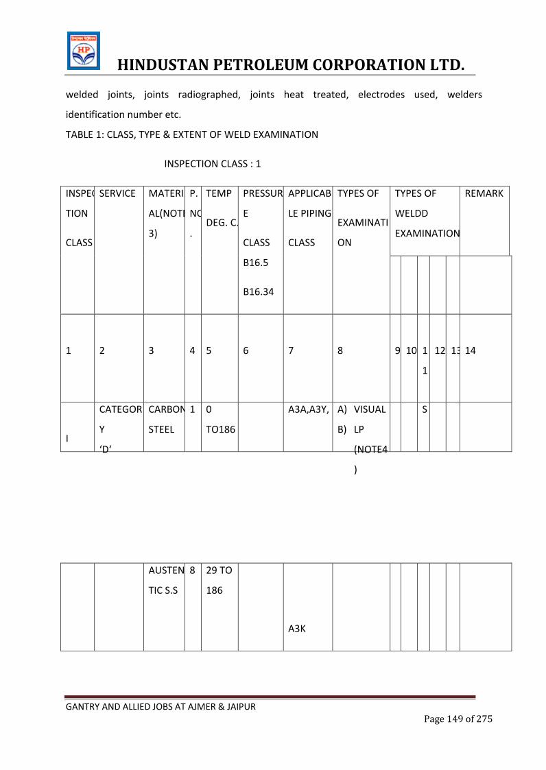
HINDUSTAN PETROLEUM CORPORATION LTD.
GANTRY AND ALLIED JOBS AT AJMER & JAIPUR Page 149 of 275
welded joints, joints radiographed, joints heat treated, electrodes used, welders
identification number etc.
TABLE 1: CLASS, TYPE & EXTENT OF WELD EXAMINATION
INSPECTION CLASS : 1
INSPEC
TION
CLASS
SERVICE MATERI
AL(NOTE
3)
P.
NO
.
TEMP
DEG. C.
PRESSUR
E
CLASS
B16.5
B16.34
APPLICAB
LE PIPING
CLASS
TYPES OF
EXAMINATI
ON
TYPES OF
WELDD
EXAMINATION
REMARK
1
2
3
4
5
6
7
8
9
10
1
1
12
13
14
I
CATEGOR
Y
‘D‘
CARBON
STEEL
1 0
TO186
A3A,A3Y, A) VISUAL
B) LP
(NOTE4
)
S
AUSTEN
TIC S.S
8 29 TO
186
A3K
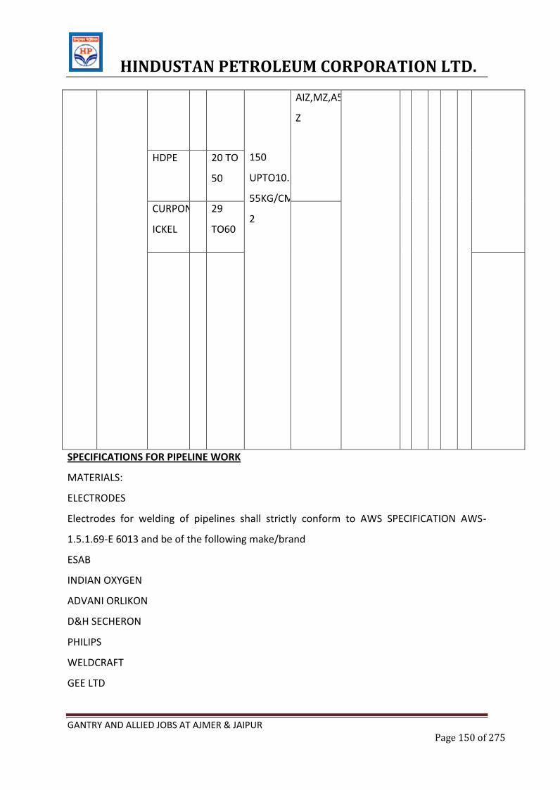
HINDUSTAN PETROLEUM CORPORATION LTD.
GANTRY AND ALLIED JOBS AT AJMER & JAIPUR Page 150 of 275
150
UPTO10.
55KG/CM
2
AIZ,MZ,A5
Z
HDPE 20 TO
50
CURPON
ICKEL
29
TO60
SPECIFICATIONS FOR PIPELINE WORK
MATERIALS:
ELECTRODES
Electrodes for welding of pipelines shall strictly conform to AWS SPECIFICATION AWS-
1.5.1.69-E 6013 and be of the following make/brand
ESAB
INDIAN OXYGEN
ADVANI ORLIKON
D&H SECHERON
PHILIPS
WELDCRAFT
GEE LTD
HINDUSTAN PETROLEUM CORPORATION LTD.
GANTRY AND ALLIED JOBS AT AJMER & JAIPUR Page 151 of 275
BOLTS AND NUTS
Bolts and nuts shall conform to the requirement of turned gauge botls of symbol 4D, 5D
and 5S, specifications in IS:1367-1962 technical supply conditions for threaded fasteners.
The screw thread shall conform to coarse series medium class referred in IS:1367-1962. All
stu& bolts shall conform to ASTM A 193 B 7 & A194 2H.
JOINTING MATERIALS (GASKETS)
The details of the gaskets to be used shall be as given below:
QUALITY : As mentioned in Job schedule.
Manufacturer : Champion or Equivalent approved by Engineer In
Charge
SERVICE : For use on all pipeline, flange joints, etc.
PREPARATION OF PIPE END
The fabrication of pipeline shall conform to IS:10234
The pipes supplied will be in random lengths of 5-7 meters generally with bevelled ends.
However, in case any ends are damaged cutting/bevelling shall be done by the contractor
at no extra cost. Cutting/bevelling will also be required to be done before welding my cut
piece of pipeline.
For pipes that are intended to be in axial alignment the place of the pipe ends shall be
square with the axis of the pipe.
The pipes which are intentionally out of axial alignment, the plane of the joint shall bisect
the angle between adjacent pipes.
All tack welded but joint assemblies shall be inspected to ensure root gap, alignment,
quality of tack welds, their root penetration section, cleaning and free from cracks. Any
substandard tack weld shall be cut and remade up to the standard before staring the
welding.
Contractor shall arrange to maintain register for stage wise inspection and clearance by site
in charge for above and any other checks as desired by site in charge.
LAYING OF PIPELINES:
Above ground pipeline:
HINDUSTAN PETROLEUM CORPORATION LTD.
GANTRY AND ALLIED JOBS AT AJMER & JAIPUR Page 152 of 275
Above ground pipelines shall laid on RCC pedestals. Pipelines shall follow the general
alignment of the ground. The height of the pedestal shall be adjusted in such a way that
clearance from the ground to the bottom of the pipeline shall not be more than 400 mm.
No flange or valve joint shall fall on support.
UNDERGROUND PIPES
A. The trench shall be excavated to proper width as decided by site in charge.
B. It should be ensured that while laying the pipes, no foreign material like stones,
sand, gunny bags, bits of welding rods, weld materials etc. are left inside the laid
pipes. At the end of each day’s work the free end of the laid pipes must be kept
properly closed with dry gunny bags.
C. The trenches shall not be backfilled till the final inspection by
radiography/hydrostatic tests are completed, and all the defects pointed out by the
Engineer-in-charge are rectified to the satisfaction of the Engineer-in-charge.
WELDING:
A. Only welders proficient in the vertical and overhead positions as per the stipulations
of ISI-817 shall be allowed to weld these pipelines. Preferably welders with
proficiency certificates from Govt. test house or equivalent recognized authority
should be deployed for the job. Optionally welders will be tested at site and the
test pieces shall be tested by radiography in an approved laboratory. All expenses
for this shall be borne by the contractor.
B. If a welder is found to perform a type of welding or in a position for which he is not
qualified he shall be debarred from doing further work. All welds performed by an
unqualified welder shall be cut and rewelded by a qualified welder at the expense of
the contractor.
C. It shall be contractor’s responsibility to arrange for and bear all costs towards
testing of welders for prequalification.
D. Welding shall be manual shielded metal arc process. Standard quality line up jigs
and fixtures which will ensure sound welds shall be used. The cutting of pipes and
welding shall conform to IS specifications and to the satisfaction of Engineer-in-
charge. The pipe shall be butt welded with three or more runs of weld.
HINDUSTAN PETROLEUM CORPORATION LTD.
GANTRY AND ALLIED JOBS AT AJMER & JAIPUR Page 153 of 275
E. Welding shall not be performed when surfaces to be welded are wet, when rain is
falling on which such surface or during the period of high winds unless the welder
and the works are shielded in an approved manner.
F. Joint preparation for welding shall be so as to leave a smooth finished profile free of
cavities and conforming to standard practice. Edges shall be cleaned of paint, rust,
scale, slag, dirt and other foreign materials before welding.
G. The thickness of the tack welds shall be similar to that of the initial root run to be
deposited in the groove and where necessary, the extremities of the tack welds
shall be dressed by grinding, chipping and flame gauged to facilitate proper fusion
when they are incorporated in the initial root run.
H. All slag and scales etc.shall be removed from the surface of each completed bead
before depositing the next bead.
I. The finished weld shall present a smooth bright and shiny surface of constant width
and uniformly spaced ripples. The welds shall be free from slag pockets, porosity,
undercutting, incomplete penetration and fusion and other weld defects.
J. The weld shall not project beyond the plain surface in butt weld by more than 2
mm.
K. All welds protrusions spatter etc.on the weld surface and adjacent area shall be
removed so as to leave the surface smooth and clean.
L. All valves, flanges risers, bends and other fittings shall be in perfect plumb and
plane. Care shall be taken to align the pipelines and bends properly to keep the
symmetry of the pipeline layout.
M. To maintain the specified alignment and gap during welding the pipes shall be
securely held in position by mechanical means and not by tack welding or by
welding on bridge place. Electrode or filler rods used for tack welding shall be of the
same quality as those used for the first run of the weld.
INSPECTION OF WELDS
The methods of inspection shall be as under:
Visual inspection shall be done for all weld joints of pipelines as well as flanges.
Dimensions of weld deposits:
HINDUSTAN PETROLEUM CORPORATION LTD.
GANTRY AND ALLIED JOBS AT AJMER & JAIPUR Page 154 of 275
The dimensions of weld shallbe checked. The size of weld shallbe as specified and it may be
slightly over but not undersize.
Shape of Profile:
The profile of the weld is affected by position of the joint but shall be uniform. In the case
of butt and corner welds the profile shall be slightly convex and in the case of fillet weld it is
usually slighlty concave.
Uniformity of Surface:
The height and spacing of the ripples shall be uniform these being indicative of quality of
workmanship.
Degree of Undercuts:
The welded joints shall be free from undercuts, but slight intermittent occurrences may be
disregarded provided that such undercuts is not in the form of sharp notch.
Smoothness of joints where welding is recommended:
The joints in the weld run shall be as smooth as possible and shallshow no pronounced
lump or crater in the weld surface.
Freedom from surface defects:
The surface of the weld shallbe free from porosity, cavities and burnts or scale.
Penetration bead in butt welds:
A slight penetration bead shall be present and it shall be reasonably uniform in width and
appearance. Intermittent occurrences of lack of penetration bead may be disregarded.
HYDROSTATIC TESTING
A) On completion of laying of entire pipeline, all open flanges except one on the line
shall be blanked of with blind flanges.
B) The trench shall be kept free of water and the pipeline surface dry. The pipeline
shall be filled with water and the pressure built up by means of test pump with a pressure
gauge to the specified pressure i.e. 10.5 Kgs/Sq.cm.
C) The pressure shall be maintained for a minimum period of 12 hours unless
otherwise specified by the Engineer-in-charge. The hydrostatic test shall be considered
positive only if there is no drop in the built up pressure at the end of the specified period.
HINDUSTAN PETROLEUM CORPORATION LTD.
GANTRY AND ALLIED JOBS AT AJMER & JAIPUR Page 155 of 275
D) All welded blind and flange joints and the seam welds on the ERW pipes shall be
inspected for leak by passing a dry hand.
E) Leaky joints shall be repaired by methods as approved by site in charge. After
repairing the leaky joints, the joint shall be re-radio graphed and entire pipeline section
shall be hydro tested to prescribed pressure. No claims for such expenditure incurred by
the contractor towards such repairs of defective work and retesting shall be entertained.
F) After hydro testing, pipeline shall be completely emptied out and the line shall be
made free from water.
RADIOGRAPHIC INSPECTION
SCOPE
This specification covers the radiographic inspection of all types of welded joints of the
main pipeline and piping system.
The welded joints shall include the following:
i. Full girth welds on the main line construction including double jointing of pipe, if
adopted.
ii. Welds for installation of block valves, insulating joints, other appurtenances and tie-ins
APPLICABLE STANDARDS
This specification shall apply in conjunction with the following (latest edition):
i.) DNV Rules for Submarine Pipeline Systems.
ii.) ASME Section V, NondestructiveExamination
iii.) ASTM E 94, Standard Practice for Radiographic Testing.
iv.) ASTM E 142,Method for Controlling Quality of Radiographic Testing.
v.) SNT-TC-IA - Recommended Practice for Nondestructive Testing Personnel Qualification
and Certification.
VI) API-1104 Standard for Welding Pipelines and Related Facilities.
PROCEDURE
The radiographic examination procedure to be adopted shall be submitted by the
Contractor.

HINDUSTAN PETROLEUM CORPORATION LTD.
GANTRY AND ALLIED JOBS AT AJMER & JAIPUR Page 156 of 275
The procedure of radiographic examination shall be qualified to the entire satisfaction of
Company/Company’s authorised Inspection agency. It shall include but not be limited to
the following requirements.
i. Manual or automatic film processing shall be done, so that they are interpretable for
atleast three years after they are produced.
ii. A single- wall exposure technique shall be used for radiography whenever practical.
When it is not practical to use a single wall technique, a double wall technique shall be
used. An adequate number of exposures shall be made to demonstrate that the
required coverage has been obtained.
iii.The quality level required for radiography shall be atleast 2% (2-2T)
iv.A densitometer shall be used to determine film density. The transmitted film density
shall be 1.8 - 2.5 throughout the weld.
The Contractor shall qualify each procedure in the presence of the Company prior to use.
The radiographic procedures are to be made of a weld joint using pipe of same diameter,
wall thickness and of material same as that used in the pipeline system.
The procedure of radiographic examination shall produce radiographs of sufficient
density, clarity and contrast so that defects in the weld or in the pipe adjacent to the
weld, and the outline and hole wires and identification no. of the penetrameter wires are
clearly discernible.
All the girth, welds of mainline shall be subjected to 10% radiographic examination The
Contractor shall furnish all the radiographs to Company/Company’s authorised
representative, immediately after processing and drying for review and approval, together
with the corresponding interpretation reports on approved formats. The details of the
radiographs along with the joint identification number shall be duly entered in a register
and signed by the Contractor and submitted to the Company/ Company’s authorised
representative for approval.
When the radiation source and the film are both on the outside of the weld and located
diametrically opposite to each other, the maximum acceptable length of film for exposure
shall not exceed the values given as per acceptable procedure. The minimum film overlap,
in each cases, shall be 40 mm. The ellipse exposure technique may be used on nominal
HINDUSTAN PETROLEUM CORPORATION LTD.
GANTRY AND ALLIED JOBS AT AJMER & JAIPUR Page 157 of 275
pipe sizes of 2 inch and smaller provided that the source to film distance used is a
minimum of 12 inch.
Three copies of each acceptable radiographic procedure (as specified) and three copies of
radiographic qualification records shall be supplied to Company. One set of the qualifying
radiographs on the job, shall be kept by the Contractor’s authorised representative, to be
used as a standard for the quality of production radiographs during the job. The other two
sets shall be retained by Company for its permanent record.
Three copies of the exposure charts relating to material thickness, kilo voltage, source to
film distance and exposure time shall also be made available to company by the
Contractor.
The Contractor on daily basis, record for each radiograph (i) Radiograph’s number (ii)
Welder/s number (iii) Approximate chainage of weld location, (iv) Whether or not the
welds meet the specified acceptance standards and (v) the nature and approximate
location of unacceptable defects observed. It must be possible to relate back to a
particular butt weld and welder on piping drawing and pipeline alignment drawing.
Each batch production of processed radiographs shall be properly packaged separately
identified by atleast the week No. and job location.
The contractor shall provide all the necessary facilities at site such as a dark room with
controlled temperature, film viewer etc. to enable the Company/Company’s authorised
representative to examine the radiographs.
The contractor, if found necessary, may modify the procedure of radiographic
examination suiting to the local conditions prevailing. This shall, however, be subject to
the approval of the Company/Company’s authorised agency.
Company/Company’s authorized representative shall have free access to all the
Contractor’s work facilities in the field.
Any approval granted by the Company/Company’s authorized representative shall not
relieve the Contractor of his responsibilities and guarantees.
RADIATION SOURCE
HINDUSTAN PETROLEUM CORPORATION LTD.
GANTRY AND ALLIED JOBS AT AJMER & JAIPUR Page 158 of 275
Radiographic examination shall be carried out using Gamma radiations at the discretion
of the Company.
LEVEL OF QUALITY
The quality level required for radiography shall be atleast 2% (2-2T)
PENTRAMETER
The image quality indication shall be used for the qualification of the welding procedure
and during examination shall produce radiographs to suit the requirement of the codes.
For radio graphs made with the source on the outside a penetrameter shall be placed on
each side of the film with the smaller wire of penetrameter turned towards the end of the
film itself. When a complete weld is radio graphed in a single exposure using a source
inside the pipe minimum three penetrameters approximately equally spaced around the
circumference shall be used. During the procedure qualification IQI shall be placed both
on the source side and on the film side.
The sensitivity limit may be considered to have been reached when the outline of the IQI,
its identification number and the wire if the required diameter show up clearly on the
radiograph.
The Company/Company’s authorized representative may authorize use of types of IQI
other than those planned, provided that they confirm with recognized standards and only
if the contractor is able to demonstrate that the minimum sensitivity level required is
obtained. For this demonstration, a test shall be carried out comparing the IQI, scheduled
and the Contractor’s to show up the identification number and other details of the
proposed IQI, which must be visible in the test radiograph. Material of the penetrameter
shall be of equivalent radiographic density to that of the material under examination.
FILM IDENTIFICATION MARKERS
All films shall be clearly identified by lead numbers, letters and/or markers. The image of
the markers shall appear on the films, without interfering with the interpretation. These
markers positions shall also be marked on the part to be radiographed and shall be
maintained during radiography.
PROTECTION AND CARE OF FILM

HINDUSTAN PETROLEUM CORPORATION LTD.
GANTRY AND ALLIED JOBS AT AJMER & JAIPUR Page 159 of 275
All exposed and unexposed film shall be protected and stored properly as per the
requirements of ASTM E94 and DNV rules.
The exposed and unexposed film shall be protected from light, heat, dust and moisture.
Sufficient shielding shall be supplied to prevent exposure of film to damaging radiation
prior to and following the use of the film for radiographic exposure.
RE –RADIOGRAPHY
The weld joints shall be re-radiographed in case of unsatisfactory quality of radiographs.
All the repaired weld joints shall be re-radiographed at repaired position in the same
manner at that followed for the original welds. In addition, the repaired weld areas shall
be identified with the original identification number plus the letter R to indicate the
repair.
When evaluating repair film radiographers shall compare each section (exposure) of the
weld with the original film to assume repair was correctly marked and original defect
removed.
The Company/Company’s authorized representative will review prior to any repair of
welds, all the radiographs of welds that contain, according to the Contractor’s
interpretation, unacceptable defects. The Company/Company’s authorized representative
will decide the final deposition of all unacceptable welds.
QUALIFICATION OF RADIOGRAPHERS
As a minimum, all personnel conducting radiographic examination shall be certified to
Level- I in accordance with ASNT document SNT-TC-IA.
All qualification certification should have current validity. Radiography will be performed
under jurisdiction of a certified ASNT Level-II Supervisor.
Interpretation of radiographs shall be carried out only by certified ASNT-Level II
Personnel.
All the records of NDT Personnel such as background and experience records, training
course records, certification records and fitness records shall be submitted to the
Company for review and approval before the NDT personnel are permitted to perform
production radiography and interpret films.
HINDUSTAN PETROLEUM CORPORATION LTD.
GANTRY AND ALLIED JOBS AT AJMER & JAIPUR Page 160 of 275
PRESERVATION OF RADIOGRAPHS
The radiographs shall be processed to allow storage of films without any discoloration for
atleast three years. All the radiographs shall be presented in suitable folders for
preservation along with necessary documentation.
All radiographs shall become property of the Company.
EQUIPMENT AND ACCESSORIES
Contractor shall make necessary arrangement at his own expense, for providing the
radiographic equipment, radiographic films and all the accessories for carrying out the
radiographic examinations for satisfactory and timely completion of the job.
For carrying out the radiographic examination contractor shall be equipped with film
processing units, film viewer, density meter etc.
RADIATION PROTECTION
Contractor shall be responsible for the protection and personal monitoring of every man
with or near radiation sources.
The protection and monitoring shall comply with local regulations.
In view of visual hazards, in the handling of Radioactive source of material, Contractor
shall be solely responsible for complying with all rules and regulations set forth by Atomic
Energy Commission or any other Government agencies of India in this regard and
Company shall not be responsible and shall be kept indemnified by the Company for all
necessary personnel shall be made available for use and maintained for immediate and
proper use by the Contractor.
HINDUSTAN PETROLEUM CORPORATION LTD.
GANTRY AND ALLIED JOBS AT AJMER & JAIPUR Page 161 of 275
E.4.STANDARD SPECIFICATION FORWELDING
CONTENTS
1. GENERAL
2. WELDING REQUIREMENTS
3. WELDING PROCEDURE QUALIFICATION
4. WELDER’S QUALIFICATION
5. WELDER’S IDENTIFICATION CARD
6. WEATHER CONDITIONS
7. BASE MATERIALS
8. FILLER MATERIALS
9. WELDING PROCESS
10. PREPARATION OF PIECES TO BE WELDED
11. WELDING TECHNIQUE FOR ROOT PASS
12. JOINT COMPLETION
1. GENERAL
This specification covers field and shop welding for carbon steel piping system.
In particular, following types of joints are considered:
Butt welds between pipes, flanges, bends, branch connection valves. etc.
Fillet welds for junction of slip on flanges; butt and socket weld fittings, reinforcing
pads, etc
The following accepted standard and procedures shall be applicable:
Standard for welding pipes and related facilities – ANSI – B 31.3. – latest edition.
Code of practice for manual for welding of mild steel – IS: 823 latest edition (for
structural work only)
HINDUSTAN PETROLEUM CORPORATION LTD.
GANTRY AND ALLIED JOBS AT AJMER & JAIPUR Page 162 of 275
In case of any variation between the provisions of the codes and the specifications given
below the later shall prevail.
2. WELDING REQUIREMENTS
All welds joining two sections of pipe, a section of pipe to a fittings or fittings shall be
performed employing qualified welding procedure and welders in accordance with Clauses
3 to 12 of this specification.
3. WELDING PROCEDURE QUALIFICATION
Welding procedure qualifications for all piping except those under the purview of IBR, shall
be as per the latest edition of Standard for welding pipelines and related facilities, ASME
section IX. The contractor shall submit the welding procedure after receipt of work order.
Owner inspector shall review, check and approve welding procedure after conducting such
tests as are necessary. It shall be the responsibility of contractor to arrange and carry out
such tests at his own costs.
4. WELDER’S QUALIFICATION
Welder’s qualification for all piping except those coming under the purview of IBR, shall be
in accordance with ASME Sec IX. Owner’s Inspector shall witness the test and certify the
qualification of each welder. Welders approved by the owners’ Inspector only shall be
employed. Contractor shall submit the welder qualification reports before the
commencement of work. It shall be the responsibility of the Contractor to carry out the
qualification test of the welders at his own cost at the job site all the tools, tackles and
auxiliaries required for carrying out Welder’s test shall be supplied by contractor at his own
cost.
5. WELDER’S IDENTIFICATION CARD
The welder shall carry on his person identification card as per Exhibit C and shall produce it
wherever demanded by Owner’s Inspector. It shall be the responsibility of the Contractor
to issue the identification card after it is duly certified by Owners inspector.
HINDUSTAN PETROLEUM CORPORATION LTD.
GANTRY AND ALLIED JOBS AT AJMER & JAIPUR Page 163 of 275
No welder shall be permitted to work without the possession of identification card. If a
welder is found to perform a type of welding or in a position or on a material for which he
is not qualified, he shall be debarred from doing further work. All such welds shall be cut
and redone by the contractor at his own cost.
6. WEATHER CONDITIONS
If the welding is to be performed during rain or strong wind, suitable protection shall be
provided for the parts to be welded and the welder.
7. BASE MATERIALS
In general this specification shall be used in welding the carbon steel materials having a
specified tensile strength of 60,000 psi or less.
Backing rings, if required, shall be similar in chemical composition to the base material.
8. FILLER MATERIALS
Electrodes:
Electrodes used for welding shall conform to IS 814 and IS 815 latest editions.
The electrodes to be used by the Contractor shall be approved by the Engineer in charge
after conducting tests as per IS: 814 testing procedure. These tests shall be carried out by
the contractor at his own cost.
The contractor shall submit manufacturer’s certificates for each batch of electrodes
supplied by him.
Electrodes shall be stored in unopened original containers. They shall be stored adequately
to prevent moisture loss or moisture absorption and shall be handled in such a manner so
as to avoid the damage of coating.
Electrodes when used shall be free of rust, oil, grease, earth or any other matter which
could be harmful for the quality of welding. The electrodes used shall be suitably to the
HINDUSTAN PETROLEUM CORPORATION LTD.
GANTRY AND ALLIED JOBS AT AJMER & JAIPUR Page 164 of 275
welding process and the base metal and the weld properties shall not be lower than those
of base metal.
9. WELDING PROCESS
Welding under this specification shall be done with the manual shielded metal arc process.
Automatic or semi automatic welding shall be done only after the procedure and materials
have been specifically approved by the Engineer in charge.
The welding shall conform to the standard codes of welding practice. Welding of carbon
steel in general shall be in accordance with IS: 823 - Code of practice for use of metal arc
welding in mild steel (for structural work only).
The welding of pipes shall conform to ANSI B 31.3 (latest edition) the compliance with this
specification does not relieve fully or partially the contractor, responsible for piping
fabrication and erection of his own responsibilities as well as on any contractual
obligations.
10. PREPARATINO OF PIECES TO BE WELDED
End Preparation
Preparation of ends to be welded will be preferably made by machining. However,
preparation of the ends may be made by flame cutting, providing all grooves and
irregularities are ground off and all the oxidation is removed.]
Cleaning
The ends to be welded shall be properly cleaned. All paint, oil, grease, rust and oxide in
general shall be removed, as well as all earth, sand or any other material which could be
harmful to the welding. Ends shall be totally dry when welded.
No dirt or debris will be permitted in the pipeline. Prior to alignment, the inside of each
joint shall be adequately swabbed, either by use of leather of canvas belt disc of proper
diameter or other improved method.
HINDUSTAN PETROLEUM CORPORATION LTD.
GANTRY AND ALLIED JOBS AT AJMER & JAIPUR Page 165 of 275
Alignment and Spacing
Pieces to be welded shall be aligned and spaced in a suitable manner, so as to hold the
ends during welding at a distance to ensure full penetration. Root opening shall not be
more than as specified. Internal misalignment shall not exceed 1.5 mm.
For pipe with thickness 4 mm or larger, the pieces to be butt welded shall be coupled by
means of pipe couplers or by yokes or bridge “C” clamps.
Owner’s inspector shall check and approve the joint fit up and alignment prior to the
commencement of welding.
11. WELDING TECHNIQE FOR ROOT PASS
For Butt Joints:
The maximum electrode size shall be 3.25 mm or 1/8 (10 SWG) and the electrode holder
shall be connected, having due regard for the polarity requirements of the electrode
approved for the use for pipe in horizontal position. Upward technique shall be used with
the recommended values of current.
The root pass of butt joints, regardless of the technique used, shall be such as to achieve
full penetration. However, projection of weld metal into the pipe bore shall not exceed
more than 3 mm. Root grooves and defective restart of the welding shall be carefully
avoided.
The weld shall be back chipped from inside by grinding or chiselling and a sealing run shall
be given.
At each interruption of welding and on completion of each run, craters, weld irregularities
and slag shall be removed by grinding or chiselling.
After the welding is started and until the joint has been completed, displacements, shocks,
vibrations or stresses shall be avoided in order to prevent cracks or breaks in the weld.
For fillet welds
HINDUSTAN PETROLEUM CORPORATION LTD.
GANTRY AND ALLIED JOBS AT AJMER & JAIPUR Page 166 of 275
The maximum electrode size shall be 4 mm or (5/32) (8 SWG)
On completion of the root pass, any visual defect or irregularities shall be ground off to
avoid defects or irregularities in the new pass.
12. JOINT COMPLETION
12.1 Electrode size of more than 8 SWG (4mm or 5/32) shall not be allowed for filling of
the weld. Upward technique shall generally be used for pipe in horizontal and vertical
position.
12.2 At each interruption of welding, and after each run of welding is completed,
chipping and slag removal shall be done.
12.3 When the welding is complete, but joints shall have a cover pass. It shall be slightly
convey and fuse into the surface to the base metal in such a manner as to have a gradual
notch free finish a good fusion at the joint edges. It shall not be chipped after completion.
Welds shall have a regular appearance and shall be free from defects.
12.4 Welder number shall be stamped along side each weld. Whenever required by the
Engineer in charge.
12.5 When welding is completed, the butt joints of piping regardless of welding methods
used, shall have a weld reinforcement referred to the outside of the pipe, not more than 2
mm for pipes not thicker than 12.
HINDUSTAN PETROLEUM CORPORATION LTD.
GANTRY AND ALLIED JOBS AT AJMER & JAIPUR Page 167 of 275
E.6.STRUCTURAL STEEL WORKS
HINDUSTAN PETROLEUM CORPORATION LTD.
GANTRY AND ALLIED JOBS AT AJMER & JAIPUR Page 168 of 275
STRUCTURAL WORK
1.0 The Specification shall apply to Steel work in GANTRY and general Structural work
2.0 FABRICATION OF STEEL STRUCTURES
2.1 SCOPE OF WORK
2.1.1 The scope of work under fabrication-includes, but not limited to, the following:
a) Preparation and supply of material indents, bolt lists bought out items list.
b) Procurement and collection of all steel materials from stockyards/stores,
including loading, transportation, unloading and slacking and storing on skids or
supports.
c) Procurement and collection of all consumables like bolls nuts, hook bolts,
washers, electrodes, paints, shims, packs, etc., including allowance for spares and
wastage.
d) Preparation and submission of fabrication drawings, modification /rectification
sketches, as made drawings, erection drawings, bill of materials, bolts lists and
shipping documents for approval of purchaser.
e) Preparation of design calculations for non-standard connections, temporary bracings
etc_ for approval of purchaser.
f) Cold straightening of section and plates, whenever they are bent and kinked.
g) Fabrication of all steel structural components covered under tender drawings,
design drawings and generally described under the scope of the project including
MS gratings, MS tube Hand rails. Gutter, down corner, portal frame etc, complete.
h) Making arrangements for and conducting tests, such as chemical analysis, physical and
mechanical tests on raw materials 'here specified/as directed by the purchaser,
HINDUSTAN PETROLEUM CORPORATION LTD.
GANTRY AND ALLIED JOBS AT AJMER & JAIPUR Page 169 of 275
i) Making arrangements for providing all facilities for conducting ultrasonic,
Radiographic tests of welds; gelling the tests conducted by reputed testing
laboratories making available test films 1 graphs, reports and interpretation.
I) Control Assembly of steel structural components at shop, wherever required.
k) Preparation of steel structural surfaces for painting as provided in the specifications
/ drawings.
I) Application for painting at shop, as specified in the design drawing/specifications.
m)Loading, transportation from fabrication workshop to site of erection and
unloading of all steel structural components 1 units / assemblies, roofing sheets,
gratings, gutter, down corner etc,.
n)Rectification of damaged structures including fixing, aligning, levelling, balling &
welding etc,
o)Preparation of "As-built" drawings.
2.2 PREPARATION OF FABRICATION AND ERECTION DRAWINGS
2.2.1 Fabrication drawings shall be prepared based on design drawings of steel
structures.
2.2.2 Drawing shall be prepared in metric system as per IS:696-1972 and IS: 813-
1986. The fabrication drawings shall specify the following details: -
a.) Type, size and length of welds in case of welded connections (specifying clearly
shop or site weld). Length of weld specified shall be effective length (excluding end
crates)
b.) n case of bolted joints, arrangement of bolts and specification of bolts, nuts etc
(specifying clearly shop and site bolls).
c.)Specification of electrode/wire flux.
HINDUSTAN PETROLEUM CORPORATION LTD.
GANTRY AND ALLIED JOBS AT AJMER & JAIPUR Page 170 of 275
d.) If required special provision to be mentioned in the drawings for handling of
structures during and after fabrication.
e.) Specification of paint and corresponding surface preparation for painting.
f.) General arrangement / marking plan.
g.) Reference to design drawings.
h.) Material list indicating mark number-wise material requirement giving size,
weight, material specification, identification number of each items, number of
pieces required etc.
i.) Layout with all connecting members with blown up joint details wherever
required, in order to specify clearly various fabrication and erection requirements
as per design drawings.
j.) Specification of preparation of mating surfaces in case of connection by HSFG
boils.
k.) Appropriate edge preparation in case of butt/groove welds in accordance
with 1S:9595-1980, for all plates and sections having thickness greater than 8
mm.
l) Erection clearances in order to facilitate smooth erection at site (ref
clause no.11.2.2.of IS: 800- 1984).
m) Each erection piece shall be clearly identified by an erection mark in these
drawings. All loose members shall be given part mark, which shall be 'wired on'
the main erection piece for dispatch.
2.2.3 Fabrication drawings shall be prepared in such a manner that Structures can
be dispatched from fabrication shop to erection site with maximum economic
HINDUSTAN PETROLEUM CORPORATION LTD.
GANTRY AND ALLIED JOBS AT AJMER & JAIPUR Page 171 of 275
transportable size, so as to reduce work involved at site to a minimum.
2.2.4 Bracings shall be connected for 50% of the capacity of the member or the
force specified in the design drawing, whichever is more (for single angle bracing
member, consider lull area as effective for this purpose).
2.2.5 Standard simple beam connections, unless otherwise stated in the
drawings, shall be designed and detailed for 60% beam shear 1 moment carrying
capacity.
2.2.6 Wherever there is risk of nuts becoming loose due to vibration, lock nuts
shall be provided, or nuts shall be welded alter alignment and lightening.
2.2.7 For all connections by permanent bolts, two nos. of washers shall be used.
One washer bearing against the head and the other bearing against the nut.
2.2.8 Detailing of structural steel members subject to dynamic loading shall be such
as to ensure smooth transition of load, as well as best behavior under stress due to
fatigue. Welding across tension flange of crane girders is not permitted.
2.2.9 For detailing connection, the allowable stress for materials, welds, bolls etc,
shall be as per IS: 800- 1984 and IS: 816-1969, or as specified in the drawing.
2.2.10 The contractor shall be responsible for design and detailing all connections.
The design of connection shall provide adequate strength for transfer of force in the
structural elements, as indicated on design drawings. Detailing shall be such that
erection shall be convenient and free from all interfaces, drilling and cutting at site.
2.3 MATERIALS
2.3-1 Structural Steel
2.3.1.1 Structural steel and other related materials for construction shall conform to
Annexure-VI and relevant IS standards and BOQ.
HINDUSTAN PETROLEUM CORPORATION LTD.
GANTRY AND ALLIED JOBS AT AJMER & JAIPUR Page 172 of 275
2.3.1.2 Due to non-availability of specified materials, suitable substitutions may be
provided with the consent of the purchaser. Such substitution shall be incorporated in the
'As-built' drawings.
2.3.1.3 All the items are to be cut as per requirements of the drawing. If joints are to be
provided in any item, in order to meet requirements of size and shape, cutting plan
showing locations of joints shall be prepared for consideration of purchaser. Joints
provided shall be incorporated in "As-built" drawings.
2.3.1.4 Rolling and cutting tolerances shall be as per IS:1852. 1985.
2.3.1.5 Only tested materials shall be used unless use of untested materials for certain
secondary structural members is permitted by purchaser- If test certificate for the
material is not available from the main producer, the following tests shall be carried out
at the discretion of the purchaser.
a) Chemical Composition
b) Mechanical Properties
C) Weld ability Test
2.3.1.6 Where steel castings are to be used the same shall conform to IS: 1030:1989.
2.3,2 Bolts and Nuts
2.3.2.1 Black hexagonal bolts, nuts and lock-nuts shall conform to IS:1363:1992.
2.3.2.2 Precision and semi-precision hexagonal bolls, screws, nuts and lock-nuts
Shall conform to IS: 1364:1992.
2.3.2.3 High tensile friction grip bolls shall conform to IS:3757:1985 and high
HINDUSTAN PETROLEUM CORPORATION LTD.
GANTRY AND ALLIED JOBS AT AJMER & JAIPUR Page 173 of 275
Strength structural nuts shall conform to IS:6623:1985, and hardened steel washers
to IS: 6649:1985.
2.3.3 Electrodes
4.3.1.1 Mild steel electrodes and high tensile steel electrodes shall conform to
IS:814:1991. Electrode to be used for submerged are welding shall conform to
specification IS:7280:1974.
2.4 STORING OF MATERIALS
2.4.1 Materials shall be stored and stacked properly ensuring that place is properly
drained and is free from dirt. It shall be ensured that no damage is caused due to
improper stacking.
2.5 MATERIAL PREPARATION
2.5.1 Cut edges shall be finished smooth by grinding or machining wherever
necessary. Sufficient allowance (3 mm to 5 mm ) should be kept in the items in case
machining is necessary.
2.5.2 Cutting may be affected by gas culling, shearing, cropping or sawing. In gas
cutting of high tensile steel, special care is to be taken to leave sufficient metal to
be removed by machining so that all metal that has been hardened by flame is
removed.
2.5.3 Sufficient shrinkage allowance (@1mm/M) shall be kept wherever heavy
Welding is involved.
2.5.4 Straightening and bending shall be done in cold condition as tar as practicable.
2.5.5 If required straightening and bending may be done by application of heat between
HINDUSTAN PETROLEUM CORPORATION LTD.
GANTRY AND ALLIED JOBS AT AJMER & JAIPUR Page 174 of 275
900°C and 1100°C. Cooling down of the heated item shall be done slowly.
2.6 DRILLING AND PUNCHING OF HOLES
2.6.1 Drilling and Punching of holes for bolts shall be done as per clause no.11.2.4 of IS:
800-1984, unless otherwise specified by the purchaser.
2.6.2 Drilling of holes for bolls during assembly shall not cause enlargement of holes
beyond permissible limit or damage the metal.
2.6.3 Holes for bolted connection should match well to permit easy entry of bolts. Gross
mismatch of holes shall be avoided.
2.6.4 Permissible deviation in holes for mild steel bolts of normal accuracy and high
strength bolts are given in the ANNEXURE-I.
2.7 ASSEMBLY FOR FABRICATION
2.7.1 Fabrication of all structural steelwork shall be in accordance with 1S:800-1984 and
In conformity with various clauses of this specification, unless otherwise specified in the
drawings.
2.7.2 Fabrication of structures shall preferably be taken up as per the sequence of
erection.
2.7.3 All erection units shall bear erection mark no. and reference drg no. at a prominent
location on the structures for easy identification at site.
2.7.4 Fabricated structures shall conform to tolerance as specified in this standard and in
1S:7215-1974_ In case of contradiction, tolerances specified in this standard shall prevail.
HINDUSTAN PETROLEUM CORPORATION LTD.
GANTRY AND ALLIED JOBS AT AJMER & JAIPUR Page 175 of 275
2.7.5 All the components of structures shall be free from twist, bend, damage etc,
2.7.6 Assembly of structures shall be carried out by using suitable jigs and fixtures in
Order to obviate distortion during welding.
2.7.7 Cutting of items specially for truss, bracing, bunker, hopper, galleries surge girder,
portal etc, shall be done only after checking of sizes as per Layout.
2.7.8 Surface, wherever machining is specified, shall be either planed or milled to ground
to ensure maximum contact.
2.7.9 If end-milling or machining is planned after the assembly i s o v e r , s u f f i c i e n t
allowance (5 mm to 15 mm) shall be kept in the items where milling/machining is to be
done.
2.7.10 If pre-bending of the plate is required to avoid welding distortion; it shall be done
In cold condition.
2.7.11 If extra joints are required to be provided in column, crane girder etc, and
Approval should be obtained from the purchaser. However, as general guidance
following is suggested. Splice joints of column and crane girder shall of full strength bull
weld and wherever possible shall be located al zones of minimum or substantially lesser
stress.
2.7.12Splice joints of flange and web should preferably be staggered.
2.7.13Sufficient trial assembly of fabricated components (despatch elements) shall be
carried out in the fabrication works to control the accuracy of workmanship.
HINDUSTAN PETROLEUM CORPORATION LTD.
GANTRY AND ALLIED JOBS AT AJMER & JAIPUR Page 176 of 275
2.7.14Where necessary, washers shall be tapered or otherwise suitably shaped to give
the heads of nuts and bolts satisfactory bearing.
2.7-15 The threaded portion of each bolt shall project through the nut at least by one
thread.
2.7.16 Tolerance of assembled components of structures are given in ANNEXURE-II
2.7.17 Permissible deviations from designed (true) geometrical form of the despatch
2.7.18 elements shall be in accordance with IS: 7215-1974.
2.8 WELDING
2.8.1.1.1 The Contractor shall work out welding procedure for Purchasers
approval,considering the following factors
Specification and thickness of steel.
Specification of electrode or land base wire.
Welding process (manual arc welding, submerged arc welding).
Type of structures to be welded (thickness of components meeting at a joint)
Pre and post heating requirement.
Preparation of fusion faces
Sequence of welding.
Weather condition.
Use of jigs and fixtures etc.
Type of non-destructive testing to be carried out.
Inspection procedure to be followed
Design requirements of the joints
2.8.2 Welding of any load bearing structure shall be carried out only by the person
who has passed welder's qualification as per IS:7318 (Part-I)-1974.
HINDUSTAN PETROLEUM CORPORATION LTD.
GANTRY AND ALLIED JOBS AT AJMER & JAIPUR Page 177 of 275
2.8.3 All metal arc welding shall be carried out as per IS:9595-1984.
2.8.4 Submerged arc welding of mild steel and low alloy steel shall be as per
IS:4353-1967.
2.8.5 Electrode shall conform to clause no.2.3.3 of this standard.
2.8.6 Electrodes shall be stored in a dry place.- Electrodes whose coatings are damaged
due to absorption of moisture or due any other reason shall not be used.
2.8.7 Low Hydrogen electrodes and flux for submerged welding shall be dried
at 250°-300° C for one hour in drying -even before use.
2.8.8 For suitability of wire flux combination, procedure test shall be carried out as
per IS: 3613-1974 if so required.
2.8.9 Welding shall be done by electric arc process. Generally submerged arc,
automatic & Semi-automatic welding shall be employed. Only where it is not
practicable, manual arc welding may be resorted to. In case of manual arc welding,
recommendations of electrode manufacturer is to be strictly followed.
2.8.10 Welding surface shall be smooth, uniform, and free from tins, tears notches
or any other defect which may adversely affect welding.
2.8.11 For multi-run weld deposit, the next run should be done only after thorough
removal of slag and proper cleaning of surface.
2.8.12 Fillet weld shall have the correct profile with smooth transition into parent
metal. Dressing of welds, if specified, shall be done by such method which does not
cause grooving and other surface defects on the weld or on the parent metal.
HINDUSTAN PETROLEUM CORPORATION LTD.
GANTRY AND ALLIED JOBS AT AJMER & JAIPUR Page 178 of 275
2.8.13 All butt welds shall start and end with run-on and run- off plates. All such plates
shall .be carefully trimmed off by gas cutting alter welding is over.
2.8.14Fillet welds shall not be stopped at corners but shall be returned round them.
2.8.15 If butt weld is to be ground flush with the surface of the member as per
drawing_ Adequate reinforcement shall be built up and then the same shall be chipped
off and ground flush: The grinding is to done in the direction of stress flow till the
transverse marks are eliminated.
2.8.16 Welding shall not be done under such weather conditions, which might adversely
affect the efficiency of the welding.
2.8.17 Manipulators shall be used wherever necessary and shall be designed to
facilitate welding and ensure that all welds are easily accessible to the operators.
2.8.18 Stress relieving after welding shall be done if especially called for in the drawing
or specification. Ends of structural members and portions of gussets receiving welding
at site, shall be left unpainted.
2.8.19 Permissible deviation in assembly of weld joints shall be in accordance with
ANNEXURE-III.
2.9 INSPECTION & TESTING
2.9.1 The HPCL/Consultant shall have free access at all times to those parts of
Contractor's or his Sub- Contractor's works which are concerned with the fabrication
of steel works and shall be afforded all reasonable facilities at all stages of preparation,
HINDUSTAN PETROLEUM CORPORATION LTD.
GANTRY AND ALLIED JOBS AT AJMER & JAIPUR Page 179 of 275
fabrication and trial assemblies far satisfying himself that the fabrication is being
undertaken in accordance with the provisions of relevant specification.
2.9.2 All gauges and templates, tools, apparatus, labour and assistance for checking shall
be supplied by the contractor free of charge. The purchaser /inspector may at hi s
discretion, check the test results obtained at the Contractor's works, by independent test
at the Government Test House or elsewhere, and should the sample so tested be found
to be unsatisfactory, the cost of such test shall be borne by the Contractor .
2.9.3 Contractor shall make all necessary arrangements for stage inspection by
purchaser/inspector during the fabrication at shop and incorporate all on -the-spot
instructions / changes conveyed in writing to the Contractor-
2.9.4 Material improperly detailed or wrongly fabricated shall be reported to the
Purchaser/Inspector and shall be made good as directed. Minor misfits which can be
remedied by moderate use of drift pins, and moderate amount of reaming and slight
chipping may be corrected in that manner; if in the opinion of the Purchaser/Inspector
the strength or appearance of the structure will not be adversely affected. In the event
the Purchaser/inspector directs otherwise, the items will be rejected and a completely
new piece shall be fabricated- The cost of correcting errors shall be to the account of the
Contractor.
2.9.5
2.9.5.1 The Purchaser/Engineer shall have the power;
a) To certify, before any structure is submitted for inspection, that the same is not in
HINDUSTAN PETROLEUM CORPORATION LTD.
GANTRY AND ALLIED JOBS AT AJMER & JAIPUR Page 180 of 275
accordance with the contract, owing to the adoption of any unsatisfactory method
of fabrication.
b) To reject any structure as"-not being in accordance with specifications & drawings-
c) To insist that no structure or parts of the structure once rejected is resubmitted
for inspection./test, except in cases where the Purchaser 1 Inspector authorized
representative considers the defects as rectifiable.
2.9.5.2 If. on rejection of structure by the Purchaser/Inspector the Contractor fails to
make satisfactory progress within the stipulated period, the Purchaser/Inspector shall.
be at liberty to cancel the contract and fabricate or authorize the fabrication of the
structures at any other place he chooses, at the risk and cost of the Contractor, without
prejudice to any action being taken in addition to terms of General Conditions of
Contract.
2.9.5.3 The Purchaser / inspector's decision regarding rejection shall be final and
binding on the Contractor.
2.9.5.4 The specifications prescribe various tests at specified intervals for ascertaining
the quality of the work done. if the tests prove unsatisfactory, Purchaser/Inspector
shall have liberty to order the Contractor to re-do the work, done in that period and/
or to -order such alterations and strengthening that may be necessary at the cost of
the Contractor and the contractor shall be bound to carryout such orders failing which
HINDUSTAN PETROLEUM CORPORATION LTD.
GANTRY AND ALLIED JOBS AT AJMER & JAIPUR Page 181 of 275
the rectification/redoing will be done by the Purchaser through other agencies and
the cost recovered from the Contractor.
2.9.5.5 Notwithstanding any inspection at the workshop the Purchaser/Inspector shall
have the liberty to reject, without being liable for compensation any fabricated
members or materials brought to site that do not conform to specifications /
drawings.
2.9.5.6 All rejected materials shall be removed from the site of fabrication by the
Contractor at his own cost and within the time stipulated by the Purchaser/Inspector.
2.10 CONTROL IN WELDING
2.10.1 The extent of quality control in respect of welds for structural elements for
both statically and dynamically loaded structures shall be as follows and shall be
conducted by the contractor at his own cost:-
2.10.1.1 Visual Examination - All welds shall be 100% visually inspected to check the
following:
i) Presence of undercuts
ii) Visually identifiable surface cracks in both welds and base metals.
iii) Unfilled craters
iv) Improper weld profile and size
v) Excessive reinforcement in weld
vi) Surface porosity
Before inspection, the surface of weld metal shall be cleaned of all slag, spatter matter
scales etc. by using wire brush or chisel.
HINDUSTAN PETROLEUM CORPORATION LTD.
GANTRY AND ALLIED JOBS AT AJMER & JAIPUR Page 182 of 275
2.10.12 Dye Penetration Test (DPI) for pipeline jobs - This shall be carried out for all
important fillet welds and groove welds for both statically and dynamically loaded structures to
check the following :
i) Surface cracks
ii) Surface porosities
Dye Penetration Test shall be carried out in accordance with American National Standard ASTM
B 165.
2.10.1.3 deleted
2.10.1.4 deleted
2.11 ACCEPTABLE LIMITS OF DEFECTS IN WELD
2.11.1 Limits of Acceptability of welding defects shall be as follows: -
a) Visual inspection & Dye Penetration Test • The limits of acceptability of defects
detected during visual inspection and Dye Penetration Test shall be in accordance
with clauses 5.9 & clause 6.10 of American National Standard ANSIIAWS D1.1-96 for
statically as well as dynamically loaded structures respectively.
b) Ultrasonic Testing - The limits of acceptability of defects detected during ultrasonic
testing shall be in accordance with clause 6.13.1 & clause 6.13.2 of American National
Standard ANSIIAWS 01.1-96 Chapter 6: Part C for statically and dynamically loaded
structures respectively.
c) Radiographic testing - The limits of acceptability of defects detected during
Radiographic testing shall be in accordance with clauses 6.12.1 & 6.12.2 of American
National Standard ANSIIAWS D1.1.96 Chapter 6 : Part C for statically and dynamically
loaded structures respectively.
2.12 RECTIFICATION OF DEFECTS IN WELDS
HINDUSTAN PETROLEUM CORPORATION LTD.
GANTRY AND ALLIED JOBS AT AJMER & JAIPUR Page 183 of 275
2.12 In case of detection of defects in welds , the rectification of the same shall be
done as follows :
i) All craters in the weld and breaks in the weld run shall be thoroughly filled with
weld.
ii) Undercuts, beyond acceptable limits, shall be repaired with dressing so as to provide
smooth transition of weld to parent metal.
iii) Welds with cracks and also welds with incomplete penetration, porosity, slag
inclusion etc. exceeding permissible limits shall be rectified by removing the length
of weld at the location of such defects plus 10 mm from both ends of defective
weld, and shall be re-welded. Defective weld shall be removed by chipping hammer,
gouging torch or grinding wheel. Care shall be taken not to damage to the adjacent
material.
2.13 ACCEPTANCE CRITERIA OF MACHINING SURFACE
2.13.1 Standard of acceptance for machined surfaces, wherever specified by designer
(eg_ in column cap plates, base plates and column shafts etc.) shall be as given as per
clause 2.13.2 & 2.13.3.
2.13.2 Maximum surface unevenness on bearing surface of -cap/ base plate shall not
exceed 0.5 mm.
2.13.3 When assembled, there must be physical contact for at least 75% of the contact
surface_(The checking shall be carried out with 0.2mm gauge .Care should be taken that
these connecting members are fixed with such accuracy that they are not reduced in
thickness during machining by more than 1.0 mm.
2.14 DESPATCH INSTRUCTIONS
HINDUSTAN PETROLEUM CORPORATION LTD.
GANTRY AND ALLIED JOBS AT AJMER & JAIPUR Page 184 of 275
2.14.1 Each despatchable structure shall bear mark no. along with reference drawing
number at two prominent locations (e.g. on flange and bottom of base plate of a
column).
2.14.2 As built' drawing shall be prepared after fabrication is completed to indicate
additions / alterations made during the process of fabrication. (Refer clause 2.3.1.2 &
2.3.1.3.)
2.14.3 Control assembly of important structures shall be done in the shop floor before
despatch to avoid mismatching. For all such important structures.match marking shall
be given at the control assembly stage in the shop floor and such match markings shall be
made dearly visible while assembling the structures at site.
2.14.4 Centre lines or column flanges and both sides of web shall be punched, preferably at top
and bottom to facilitate alignment after erection.
2.15 COMPLETION DOCUMENTS
2.1 5.1 On completion of work, the Contractor shall submit to the Purchaser the following
documents:-
a. The technical documents according to which the work was carried out.
b. Copies of the 'As built" drawings showing thereon all additions and alterations made
during the fabrication.
c. Manufacturer's test certificates
d. Certificates/documents on control checking
e. Test of welds
2.15.2 Inspection Certificates shall be issued to the contractor for the structures found
HINDUSTAN PETROLEUM CORPORATION LTD.
GANTRY AND ALLIED JOBS AT AJMER & JAIPUR Page 185 of 275
acceptable in all respects by the Purchaser/Inspector.
2.16 In addition to provision of erection and transport equipments, the scope of work includes
supply of tools and tackles, consumables, materials, labour and supervision and shall cover the
following:-
a. Storing and slacking of all fabricated structural components/units/assemblies at site
storage yards till the time of erection.
b. Transportation of structures from storage yard to site of erection including multiple
handling, if required.
c. All minor rectification / modifications such as :-
i) Removal of bends, kinks, twists etc. for parts damaged during transportation and
handling.
ii) Reaming of holes which do not register or which are damaged, for use of next higher
size bolt.
3.2 Erection Drawings
3.2.1 The approved erection drawings and any approved arrangement drg,
specification or instruction accompanying t h em shall be followed in erecting
structures.
3.3Erection of Structures
3.3.1 Erection work shall be taken up after receipt of clearance from the purchaser.
3.3.2For safety requirements during erection, provisions in IS:7205:1974,
IS.7969:1975 and other relevant Indian standards shall be followed.
3.3.3 Erection shall be carried out with the help of maximum mechanisation possible.
3.3.4 Prior to commencement of erection, all the erection equipment ,tools, tackles,
HINDUSTAN PETROLEUM CORPORATION LTD.
GANTRY AND ALLIED JOBS AT AJMER & JAIPUR Page 186 of 275
ropes etc. shall be tested for their load carrying capacity. Such tests may be repeated
al intermediate stages also it considered necessary and frequent visual inspection
shall be done of all vulnerable areas and components to detect damages or distress
in the erection equipment, if any.
3.3.5 Following shall be taken care of during erection, whenever necessary:-
3.3.5.1 Temporary bracing, whenever required, shall be provided to sustain forces
due to erection loads and equipment etc. Erected parts of the structures shall remain
stable during all stages of erection when subjected to the action of wind, dead
weight and erection forces etc. Specified sequence of erection of vertical and
horizontal structural members shall be followed.
3.3.5.2 Elected members shall be held securely in place by bolts to take care of dead
load, wind load and erection load.
3.3.5.3 All connections shall achieve free expansion and contraction of structures
wherever provided.
3.3.5.4 No final bolting or welding of joints shall be done until the structure has been
properly aligned.
3.3.5.5 For positioning beams, columns and other steel members, the use of steel
sledges is not permitted.
3.3.5.6 Instrumental checking of correctness of initial setting out of structures and
adjustment of alignment shall be carried out in sequence and at different stages as
required. The final leveling and alignment shall be carried out immediately after
completion of each section of a building.
HINDUSTAN PETROLEUM CORPORATION LTD.
GANTRY AND ALLIED JOBS AT AJMER & JAIPUR Page 187 of 275
3.3.5.7All structural members shall be erected with erection marks in the same
relative position as shown in the appropriate erection and shop drawings.
3.3.5.8 The contractor shall design, manufacture, erect and provide false-work,
staging temporary support etc. required for safe and accurate erection of structural
steelwork and shall be fully responsible for the adequacy of the same.
3.3.5.9 The Contractor shall also provide facilities such as adequate temporary
access ladders, gangways, tools & tackles, instruments etc., to purchaser for his
inspection at any stage during erection.
3.4 Field Connections
3.4.1 Assembly by permanent bolts.
3.4.1.1 The numbers of washers on permanent bolts shall not be more than two (and
not less than one) for the nuts and one for the bolt head.
3.4.1.2 Wooden rams or mallet shall be used in forcing members into position in
order to protect the metal from injury or shock.
3.4.1.3 Where bolting is specified on the drawing, the bolts shall be tightened to the
maximum limit. The threaded portion of the each boll shall be project through the
nut by al-least one thread. Tapered washers shall be provided for all heads and nuts
to achieve uniform bearing on sloping surface.
3.4.1.4 To prevent loosening of nuts, spring washers or lock- nuts shall be
provided as specified in the design/shop drawings.
3.4.1.5 All machine-fitted bolts shall be perfectly tight and the ends shall be
HINDUSTAN PETROLEUM CORPORATION LTD.
GANTRY AND ALLIED JOBS AT AJMER & JAIPUR Page 188 of 275
checked to prevent nuts from becoming loose. No unfilled holes shall be left in any
part of the structures.
3.4.2 Assembly by welding
3.4.2.1 All field assembly by welding shall be executed in accordance with the
requirements for shop fabrication. Where the steel has been delivered painted, the
paint shall be removed before field welding for a distance of at least 50 mm on either
side of the joints to be welded.
3.4.2.2 All other requirements in welding shall be in accordance with clauses
specified under Section-1 of this specification.
3.4.3 Assembly by High Strength Friction Grip Bolls (HSFG)
3.4.3.1 Assembly of structures with HSFG bolts shall conform to IS: 4000-1992.
3.4.3.2 The mating surfaces shall be prepared in accordance with the requirements of
design in order to achieve required properties to develop adequate friction between
the surfaces.
3.4.3.3 The mating surfaces shall be absolutely free from grease, lubricant, and dust. Rust
etc and shall be thoroughly cleaned before assembly.
3.4.3.4 The nuts shall be tightened up-to the specified torque with the help of torque
-wrench or by half- turn method with the help of pneumatic wrench lever.
3.4.3.5 The direction of tightening of the nuts shall be from the middle toward the
periphery of assembly.
3.4.3.6 After desired tightening the bolt heads, nuts and edges of the mat, i.e. surfaces
HINDUSTAN PETROLEUM CORPORATION LTD.
GANTRY AND ALLIED JOBS AT AJMER & JAIPUR Page 189 of 275
shall be sealed with a coat of paint to obviate entry of moisture
3.5 ACCEPTANCE STANDARD OF-MELDING
3.5.1 Acceptance standard of welding shall be as specified in SECTION-2 of this
specification.
3.6 BEDDING AND GROUTING
3.6.1 Base plates shall be set to elevations shown on the drawings, supported aligned
and levelled using steel wedges and shims or by other approved methods. Plates shall
be levelled properly, positioned and the anchor boss tightened.
3.6.2.2Bedding/grouting shall be carried out until sufficient number of columns have
been properly aligned, levelled and plumbed and sufficient number of girders, beams,
trusses and bracings have been put in position to the satisfaction of purchaser. The
bedding shall be carried out by the use of structural grade grout of approved
manufacturer.
3.7 PAINTING AFTER ERECTION
3.7.1 The painting shall be as per painting specification (SECTION-5) of this standard)
and instruction given on drawings.
3.7.2 Site painting shall not be done in frosty or foggy weather or when humidity is such as
to cause condensation on the surface to be painted.
3.8 ERECTION TOLERANCES
Maximum permissible tolerances in erected steel structures shall be as given in
ANNEXURE-IV.
3.9 ACCEPTANCE OF WORK
HINDUSTAN PETROLEUM CORPORATION LTD.
GANTRY AND ALLIED JOBS AT AJMER & JAIPUR Page 190 of 275
3.9.1 Acceptance of erected steel structures shall be either after completion of
erection of the whole building or in blocks.
3.9.2 Preliminary acceptance certificates will be given in the following cases:-
i) Any steelwork or part thereof embedded in concrete.
ii) Steel structures which are to be covered in the process of carrying out
further work.
3.10 DOCUMENTATION
3.10.1 The following documents shall be prepared at the time of acceptance of
erected structures.
i) Documents showing actual deviations made during execution of erection
work and approval of competent authority.
ii) Documents showing acceptance of embedded structures.
ii) Certificate of documents on control checking and test of materials (if any)
and weld,
iii) Data and result of geodetic measurements obtained while checking the
erection of the structures.
3.10.2 Copies of "As-Built" drawing showing thereon all additions and alternations
which took place between approval of drawing and erection of structures.
4.0 FABRICATION AND ERECTION OF MISCELLANEOUS STRUCTURES
4.1 ROOF AND SIDE CLADDING WITH .55 mm SINGLE SKIN CLIP ON ROOFING SYSTEM
WITH GALVALUME SHEETS
4.1.1 The scope of work shall cover:
a. Preparation of drawings showing layout and size of fibre sheets- used details of
connections and flashings, bill materials.
HINDUSTAN PETROLEUM CORPORATION LTD.
GANTRY AND ALLIED JOBS AT AJMER & JAIPUR Page 191 of 275
b. Procurement and supply sheets of .55 MM TCT Galvalume sheets all sizes
(Interarch/ Make or equivalent) flashings and fittings like corner pieces. Apron
pieces, ridges, cutting and bending of sheets wherever required; drilling of holes
all as per specification and drawings.
c. Procurement and supply of GI hook bolts, clips, and nuts, GI switch bolts and
nuts, clips, bitumen washers, GI diamond or limpet washers.
d. Loading, transportation, unloading and delivery of sheeting material from
place of procurement to erection site.
e. Provision of all tools, tackles, equipment. labour supervision and
services required for the satisfactory completion of the work specified
herein and on the drawings.
f. Erection in position of t sheets for rooting, walling, louvres; erection of
all (lashings, fittings like ridges, valleys, gutters, corners, apron etc. at all
locations all work as per drawings and specifications.
4.1.2 The fixing of the sheet shall be done by the approved manufacturer
including the design of the clip on system. The entire sheet system shall be
guaranteed for a minimum of 5 years and shall be replaced if damaged free of
cost.
4.1.3 to 4.1.5 Deleted
4.1.6 ERECTION
4.1-6.1 Erection is to be carried out with the lay of the side laps such that under
the prevailing wind, rain. is not driven into the lap. The sheers shall be laid so that
side laps in any two consecutive rows are staggered.
4.1.6.2 Broken or otherwise damaged sheeting shall not be erected.
HINDUSTAN PETROLEUM CORPORATION LTD.
GANTRY AND ALLIED JOBS AT AJMER & JAIPUR Page 192 of 275
4.1.6.3 Cutting, framing and trimming of all openings required shall be carried out al
site.
4.3.Grated Walkways/Grilled Flooring:
4.3.1 Unless otherwise stated all grill flooring shall be designed for in addition to its
self weight. for a superimposed load of 500 kglm2 or the alternative minimum load
specified in IS:875 or the incidental load, due to erection, operation or maintenance or
as specified in the drawing whichever is more critical. The maximum deflection due to
dead load and live load should not be more than 1/200 span.
4.3.2 Material used for fabrication shall conform to IS:2062-1999.
4.3.3 Grill flooring shall be fabricated from flats of size not less than 30x5 mm.
Located at a spacing of not less than 40 mm and shall be provided with suitable
transverse members to provide rigidity. Fabrication shall make provision to connect
the flooring panels by bolls or by bolls and clips or welding to supporting members as
per drawings. Provision shall also be made to interconnect the adjacent panels by bolts
or by bolts and clips to prevent movement of floor panels. Top surface of all
bars/members shall be flush giving a neat appearance. Welding of different members
shall be by electroforge, electric resistance or similar type of welding so that there are
no crude weld deposits or lumps.
4.3.4 If permitted, grated walkways may be fabricated by manual arc welding.
However, the welding shall be finished smoothly by proper grinding/filing.
4.3.5 The fabricated floor panels shall be cleaned of all rust, dust grease, oil, mill
HINDUSTAN PETROLEUM CORPORATION LTD.
GANTRY AND ALLIED JOBS AT AJMER & JAIPUR Page 193 of 275
scale, weld flux etc., by wire brushing or by suitable other means and made ready for
painting. Painting shall be by cold dip process. First dip shall be in anti-saline metallic
primer. After the primer paint has completely dried, the grill flooring shall be dipped
for the second time in heavy duty anti-corrosive and wear resistant bituminous black
paint. Minimum DFT of anti-saline primer shall be 25 microns and minimum OFT of
finishing paint shall be 75 microns or as specified in the BOQ.
4.3.6 For cold dip painting a thinner recommended by the manufacturer in suitable
quantities shall be added. During cold dip painting care shall be taken to guard
against sagging or flow-down of paint.
4.3.7 The gratings when erected around opening, shall have circular bands.
4.3.8 Sample grating shall be got approved before taking up full scalemanufacture.
5 PAINTING OF STEEL STRUCTURES
5.1 SURFACE PREPARATION FOR PAINTING
5.1.1 GENERAL
The steel surface which is to be prepared shall be cleaned of dirt and grease and the
heavier layers of rust shall be removed by grinding prior to Actual surface preparationto
a specified grade.
Surface preparation to be followed prior to painting shall be based on the requirement
of a particular painting system as per clause 5.3. One of the following specifications for
surface preparation is to be followed as per requirement.
5.1.2 MECHANICAL CLEANING
HINDUSTAN PETROLEUM CORPORATION LTD.
GANTRY AND ALLIED JOBS AT AJMER & JAIPUR Page 194 of 275
5.1.2.1 (a) Manual/Power tool cleaning.
Manual/power tool cleaning shall be done as per grade St-2 or. St-3,d Swedish Standard
Institution SIS 055900.
i) Grade 5t-2: Thorough scraping and wire brushing, machine brushing, grinding etc. This
grade of preparation shall remove loose 'mill scale, rust and foreign matter. Finally the
surface is to be cleaned with a vacuum cleaner or with clean compressed air or with
clean brush. After preparation, the surface should have a faint metallic sheen. The
appearance shall correspond to the prints designated 5t-2.
ii) Grade St-3: very thorough scraping and wire brushing, machine brushing, grinding
etc. The surface preparation is same as for grade St-2 but to be done much more
thoroughly. After preparing the surface, it should have a pronounced metallic sheen
and correspond to the prints designated St-3.
5.1.2.1(b) Blast cleaning
The surface shall be blast cleaned using one of the abrasives: chilled cast iron or
malleable iron and steel at a pressure of 7 kgrcm2 at appropriate distance and angle
depending on nozzle size maintaining constant velocity and pressure. Chilled cast iron,
malleable iron and sleet shall be in the form of shot or grit of size not greater than
0.055' maximum in case of steel and malleable iron and 0.04" max in case of chilled
iron. Compressed air shall be free from moisture and oil. This method will remove
loosely adherent materials as well as adherent scales and mill scales. Prior to
application of blast, heavy deposit of oil and grease are removed by, solyent cleaning
and excessive surface scales are removed by hand tools or p ower tool-cleaning. The
surface shall be cleaned to Sa - 2 ' /2 or SSPC-SP6 quality i.e. 95 % of surface area is
free from al l rust, mill scales and visible residues, foreign-materials, etc. The blast
cleaning is not recommended for sheet metal work. On completion of blast cleaning
operation the blasted surface shall be clean and free from any scale or rust and must
show a grey white metallic lusture. Primer or first coat of paint shall be applied
HINDUSTAN PETROLEUM CORPORATION LTD.
GANTRY AND ALLIED JOBS AT AJMER & JAIPUR Page 195 of 275
witthn_4 hours of surface preparation. II oxidation has occurred between blasting and
application of primer, the surface should be re-blasted to specified visual standards.
The surface profile should be.AiLto_75_Micr.ons.
5.2 PAINTS AND PAINTING
5.2.1 For use of specific painting system, the paint manufacturer's specification shall
prevail.
5.2.2 General compatibility between primer and finishing paints shall b e established
through the paint manufacturer supplying the paints.
5.2.3 Before buying the paint in bulk, it is recommended to obtain sample of paint and
establish "Control Area of Painting". On control area surface preparation and painting
shall be carried out in the presence of manufacturer of paint.
5.2.4In order to ensure that the supplied paint meets the stipulation in design drawing!
specification, if required, samples of paint shall be tested in Laboratories to establish
quality of paint with respect to' (i) Viscosity (ii) adhesion! bond of paint in steel
surfaces (iii) adhesion/simulated salt spray test (iv) chemical analysis (percentage of
solids by weight) (v) normal wear resistance as encountered during handling &
erection (vi) resistance against exposure to acid fumes etc.
5.2.5 Whole quantity of paint for a particular system of paint (shall be obtained from the
same manufacturer).
5.2.6 Thinners, wherever used, shall be as per recommendation of the paint
manufacturer.
HINDUSTAN PETROLEUM CORPORATION LTD.
GANTRY AND ALLIED JOBS AT AJMER & JAIPUR Page 196 of 275
5.2.7 Areas which became inaccessible after assembly of structures shall be painted
before assembly, after cleaning the surfaces as specified.
5.2.8 Wherever shop primer painting is scratched, abraded or damaged, the surfaces
shall be thoroughly cleaned using emery paper and power driven wire brush wherever
warranted, and touched up with corresponding primer. Touching up paint shall be
matched and blended to eliminate conspicuous marks.
5.2.9 If more than 50% of the painted surface of an item requires repair, the entire
item shall be mechanically cleaned and new primer coats shall be applied followed by
finishing coats as per painting specification.
All field welded areas on shop painted item shall be mechanically cleaned (including the
weld area proper, adjacent areas contaminated by weld spatter or fumes and areas
where existing primer. Intermediate finishing paint is burnt). Subsequently, new primer
and finishing coals of paint shall be applied as per painting specification.
5.2.10 Application of paint shall be by air less spraying or brushing as per IS:487-1985
and in uniform layers of 50% overlapping strokes. Painting shall not be done when the
temperature is less than 5°C or relative humidity more than 85%, unless manufacturer’s
recommendations permit. Also painting shall not be done in frosty or foggy weather.
During application, paint agitation must be provided wherever such agitation is
recommended by the manufacturer.
5.2.11 Paint shall be applied at manufacturers recommended rates. The number of
coals shall be such that the minimum dry film thickness (OFT) specified is achieved. The
HINDUSTAN PETROLEUM CORPORATION LTD.
GANTRY AND ALLIED JOBS AT AJMER & JAIPUR Page 197 of 275
dry film thickness of painted surfaces shall be checked with ELCOMETER or measuring
gauges to ensure application of specified OFT.
5.2.12 All structures shall receive appropriate number of primer and finishing coats in
order to achieve overall DFT as per design drawings) specifications. First coat of primer
paint shall be applied not later than 2-3 hours after preparation of surface, unless
specified otherwise.
5.2.13 The finishing paint as specified shall be of approved colour and quality. The
under coal shall have different tint to distinguish the same from the finishing coat.
5.2.1 4 Edges, corners, crevices, depressions, joints and welds shall receive special
attention to ensure that they receive painting coats of the required thickness.
5.2.15 Machine-finished surface shall be coated with white lead and tallow before
shipment or before being put into the open air.
5.2.16 Parts of surfaces embedded in concrete shall be thoroughly cleaned of grease,
rust, mill scale etc. and shall be given a protective coat of Portland cement slurry
immediately after fabrication. No paint shall be applied on this part.
5.2-17 Zinc-rich primer paints, which have been exposed several months before
finishing coat is applied, shall be washed down thoroughly to remove soluble zinc salt
deposits. In similar circumstances, the surfaces of paint cased on epoxy resin should be
abraded or lightly blast cleaned to ensure adhesion of next coat.
5.2.18 Surfaces which cannot be painted but require protection shall be given a: coat
of rust inhibitive grease according to IS.958-1975 or equivalent -International standard.
HINDUSTAN PETROLEUM CORPORATION LTD.
GANTRY AND ALLIED JOBS AT AJMER & JAIPUR Page 198 of 275
5.3 PAINTING SYSTEM
The recommended painting system for general service requirement of steel structures
covering surface preparation, application of primer coats, intermediate coats (if necessary)
and final coats to develop the required minimum dry film thickness on steel surface is
indicated in ANNEXURE – V
6.0 SALIENT POINTS
6.1 QUOTATION
6.1.1 The bidder should ascertain himself, by- a visit to the site if necessary, the actual
site conditions, local factors etc. The Contractor shall bear full responsibility for
deductions and conclusions as to the nature and conditions under which the work is to
be executed, including effect of climate, rainfall etc. Failure to do so will not absolve
the Contractor of his responsibilities about the proper execution of the job. No claims
for extra payments due to any special site conditions and ignorance of site conditions
will be considered after the acceptance of his quotation.
6.1.2 Deleted.
6.1.3 The cost of MS bolts (permanent and erection), washers, electrodes. putty. gases,
cost of straightening the raw materials (hot bending not permitted), cutting of flats
from plates and providing splices, paints, tool, plants, etc. as required for the work
shall be deemed to be included in the quoted price.
6.1.4 All handling and transport charges of raw materials and fabricated structures,
including double handling if required, for completion of the work in accordance with
time schedule are deemed to be included in the quoted price.
HINDUSTAN PETROLEUM CORPORATION LTD.
GANTRY AND ALLIED JOBS AT AJMER & JAIPUR Page 199 of 275
6.1.5 Cost of NOT of welds as per specification shall be borne by the Contractor. For the
welds found defective, the cost of retest shall be borne by the contractor in addition to
the cost of rectification or replacement of the defective part.
6.2 Deleted
6.3 PROGRAMME
6.3.1 A monthly time bar chart for various activities like procurement of steel,
preparation and approval of fabrication drawings, fabrication, despatch to site, erection
and alignment, sheeting and painting etc. giving starting and completion dates of all
activities, shall be submitted along with the bid without which the bid may not be
considered for evaluation.
6.3.2 The contractor shall also furnish his overall planning of construction program, the
capacity of equipment he proposes to deploy on various components of work etc. for
prior approval of purchaser.
6.3.3 All programs on procurement of raw steel and other materials, preparation of
drawings, fabrication and despatch shall match with the sequence of erection of
different structural components and different building/units, of the project as per
network planning.
6.3.4 The purchaser may change or alter the detailed working program for the
sequence of work and for the fabrication of components of structures, within the
frame work of the agreed schedule, which will be binding on the Contractor.
6.3.5 If due to design or other stipulations in the bid or requirements at site, a
HINDUSTAN PETROLEUM CORPORATION LTD.
GANTRY AND ALLIED JOBS AT AJMER & JAIPUR Page 200 of 275
particular sequence of overall construction has to be followed due to which certain
interruptions to any one or more items of work are inherent, no claims for such
interruption will be admissible.
6.4 DRAWINGS
6.4.1 The Contractor will be supplied with design drawings by the Purchaser-
6.4.2 Based on the design drawings, the Contractor shall prepare general
arrangement/marking drawings, fabrication drawings, erection drawings, bill of
materials, shipping documents and nut and bolt lists. Bill of materials shall form part of
fabrication drawings and shall be included in the body of the drawing or prepared
separately. Two copies of drawings and documents shall be submitted to the
Purchaser for their scrutiny and approval. One set of the Fabrication drawings will be
returned to the Contractor with a stamp signifying 'Approved', "Approved as noted" or
Not Approved" on the drawing. After the final approval by the Purchaser the
Contractor shall furnish to the Purchaser within 2 weeks.... six copies of the approved
Fabrication drawings, and erection drawings.
6.4.3 Despite approval of purchaser, Contractor shall riot be relieved of his
responsibilities for the accuracy of the detailed dimensions shown thereon and the
safety of all structural connections as per forces indicated in the design drawings.
6.4.4 Soon after the fabrication of steel work pertaining to a particular drawing is
completed, immediate steps shall be taken by Contractor to incorporate in the
approved fabrication drawings, all the authorised corrections, additions and alterations
HINDUSTAN PETROLEUM CORPORATION LTD.
GANTRY AND ALLIED JOBS AT AJMER & JAIPUR Page 201 of 275
made during the course of fabrications and 2 sets of the same shall be submitted to
purchaser for his record.
6.4.5Notes on-specifications shown on design drawings shall be considered as
superseding or overriding the specifications given elsewhere, with which they
conflict. On all drawings, dimensions shown in figures shall be acted upon.
6.4.6Two sets of erection drawings shall be submitted to the„Purchaser showing
thereon all authorised additions and alterations during the process of erection.
These drawings together with drg under clause 6.4.4 shall be treated as “ As Built"
drawings.
6.4.7Supply and distribution of fabrication drawings and other documents like bolt
list, etc. for the Contractor's own use or for the use of his Sub-contractors shall be
the responsibility of the Contractor
6.4.8The fabrication work shall be taken up only after the drawing is approved.
6.4.9The detailer shall ensure the fabrication / erection drawings are prepared in
total discussion with the purchaser / Consultant/HPCL , if necessary the detailer
should send his engineer to purchaser 1 Consultant/HPCL time to time for
discussion during the course of preparation of drawings.
6.5 MATERIAL
6.5.1The Contractor shall arrange and procure all steel sections, plates, roof
Sheets, glazings, flashings, fixtures and fittings required for sheeting and glazing,
aluminium or MS astragals and frames for glazing , clips, all the consumables like
HINDUSTAN PETROLEUM CORPORATION LTD.
GANTRY AND ALLIED JOBS AT AJMER & JAIPUR Page 202 of 275
bolts, turned and fitted bolts, nuts including spares- and service bolts, washers of
different types, electrodes, gas, shims, packs, paints, etc. for completing the work
satisfactorily and the cost of the same shall be deemed to have been covered in his
quoted price.
6.5.2 If assistance is required by the Contractor in obtaining permits/proprieties in
allotment of controlled/scarce materials, if any, the same may be extended by the
Purchaser by way of issue of recommendation letter, essentiality it certificate etc.
to Government Authorities_ Delay, if any, in obtaining the materials will not
constitute a ground for claiming any compensation or extension of time.
6.5.3 Where any raw materials required for the execution of the contract is procured
with the assistance of the Purchaser or permit /licence /quota certificate or release
order issued by or on behalf of or under authority of Purchaser or by any officer
empowered on their behalf by law, or where advance payments are made to the
Contractor to enable him to purchase such raw material for execution of work, the
Contractor:
i) Shall hold such materials as trustee for the Purchaser.
ii) Shall use such materials economically and solely for the purpose of the contract.
iii) Shall not dispose of the same without prior permission in writing from the
Purchaser.
iv) Shall maintain and produce due documents indicating stock position /
consumption of such materials from time to time, as required by purchaser.
6.14 BASIS OF PAYMENT
HINDUSTAN PETROLEUM CORPORATION LTD.
GANTRY AND ALLIED JOBS AT AJMER & JAIPUR Page 203 of 275
6.14.1 The tenderer shall agree to the payment terms given in the tender. As the
quantities mentioned are estimated quantities, payment will be made on the actuals as
per the agreed rates.
6.15 MEASUREMENTS
6.15.1 Structural Steel
Structural steelwork will be measured by the metric tonne and as per
IS:1200 (part-8)- 1993 and 15:1200 (part-9)-1973 subject to provisions
outlined below:-
a. The calculation of quantities shall be based on unit on weights for
structural sections as given in 1S:808-1989 in the case of mild
steel/SAIL-MA Steel plates, the calculated weights shall be based on
78.5 kg per square metre per centimetre thick plate. The payments
will be made on the basis of weights of members given in the approved
fabrication drawings. However, any changes on the above weights
during fabrication erection, payment shall be based on sketches
Approved by the purchaser.
b. In the event the LS_ does not specify any mode of measurement for a
particular item of work, the same shall be measured as per any other
relevant international standard or as directed by the Purchaser.
c. The weight of all plates and sections shall tae calculated from the
approved drawing using the minimum overall square or rectangular
dimensions and theoretical weight, no deduction being made for skew
cuts, holes etc. In the case of plates, other than gussets, the actual
dimensions shown on approved drawings will apply unless approved
otherwise by the purchaser based on cutting diagram of mother
plates.
HINDUSTAN PETROLEUM CORPORATION LTD.
GANTRY AND ALLIED JOBS AT AJMER & JAIPUR Page 204 of 275
d. The weight of all welding runs, bolt, stanchion base packing, cuttings
to aste and rolling margins, and coatings of paint, will be excluded
from the measured weight and shall be deemed to have been allowed
for in the rates for structural steelworks quoted by the Contractor.
e. Temporary works and all other materials not included in the
permanent works shall Uri excluded from any measurement for
payment.
6.16 Roofing she e t s (Galvalume) & Colour Coated Toughed Sheets
6.16.1 Sheeting for roof slopes, louvers of big size and side cladding shall be measured
by the square metre of net laid area, as specified and shown on the drawings.
6.16.2 No allowance shall be made for wastage, cut outs, overlaps etc. in the
measurement.
6.16.3 The unit of measurement as specified in clause 6.16.1 shall include all fasteners,
(lashings and fittings such as ridges, corners, aprons and other accessories. . .
6.16.4 No deductions shall be made for openings for area less than a single sheet. Also
no extra payment will be made for making opening and installing ventilation chimneys
on roof.
6.17 PRELIMINARY ACCEPTANCE
6.17.1 After completing the erection of a unit or portion thereof, the Contractor shall
give a notice in writing slating that the job is complete in all respects and ready for
preliminary acceptance .The job shall be jointly inspected visually by representatives of
Contractor and Purchaser. All observed defects and omissions as per drawing and
specification shall be noted down. If the defects are not major in - the opinion of the
purchaser/Purchaser's representative, the Contractor will be issued a preliminary
acceptance certificate mentioning the defects, deficiencies and omissions which shall be
made good by the Contractor within a period of 4 weeks.
6.18 FINAL ACCEPTANCE
HINDUSTAN PETROLEUM CORPORATION LTD.
GANTRY AND ALLIED JOBS AT AJMER & JAIPUR Page 205 of 275
6.18.1 Before commencement of inspection for-final acceptance of the building or unit,
the Contractor shall make available two complete sets of all drawings, representing "AS
BUILT" drawing, (Le. all additions and alterations done during fabrication arid erection
shall be incorporated in the drgs, Refer clause 6.4.4 & 6.4.6.
6.18.2 The Contractor shall make good all defects deficiencies and omissions noted
down during preliminary acceptance (Refer clause 6.17.1) and shall inform in
advance the Purchased his representative for conducting inspection, for final
acceptance. Final acceptance certificate will be issued by the Purchaser / his
representative only after all defects deficiencies / omissions noted under
Preliminary Acceptance have been rectified.
ANNEXURE-I
Permissible deviations in pitch and gauge of holes for bolts of normal accuracy (high
strength balls included
Description Hole dia(mm) Permissible deviation Per. Dev in group
In spacing(mm) (mm)
CS Low al.stl
a. Deviation up to 17 +1 No limit
In hole Above 17 +1.5
Diameter
b. Ovality up to 17 +1 No limit
above 17 +1.5
HINDUSTAN PETROLEUM CORPORATION LTD.
GANTRY AND ALLIED JOBS AT AJMER & JAIPUR Page 206 of 275
c. Curves ex Not permissible
one mm & cracks
on holes
d. Non coincidence up to 50%
of holes in separate
Details of assembled unit
up to 1 m
e. above 1 m up to 10%
f. Slope Up to 30% No limit No limit
of axis of Tk of unit
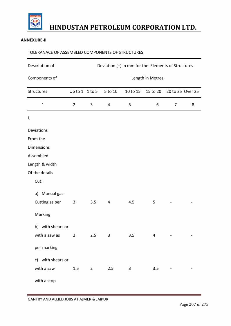
HINDUSTAN PETROLEUM CORPORATION LTD.
GANTRY AND ALLIED JOBS AT AJMER & JAIPUR Page 207 of 275
ANNEXURE-II
TOLERANACE OF ASSEMBLED COMPONENTS OF STRUCTURES
Description of Deviation (+) in mm for the Elements of Structures
Components of Length in Metres
Structures Up to 1 1 to 5 5 to 10 10 to 15 15 to 20 20 to 25 Over 25
1 2 3 4 5 6 7 8
I.
Deviations
From the
Dimensions
Assembled
Length & width
Of the details
Cut:
a) Manual gas
Cutting as per 3 3.5 4 4.5 5 - -
Marking
b) with shears or
with a saw as 2 2.5 3 3.5 4 - -
per marking
c) with shears or
with a saw 1.5 2 2.5 3 3.5 - -
with a stop
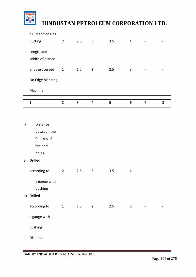
HINDUSTAN PETROLEUM CORPORATION LTD.
GANTRY AND ALLIED JOBS AT AJMER & JAIPUR Page 208 of 275
d) Machine Gas
Cutting 2 2.5 3 3.5 4 - -
i) Length and
Width of planed
Ends processed 1 1.5 2 2.5 3 - -
On Edge planning
Machine
1 2 3 4 5 6 7 8
II
i) Distance
between the
Centres of
the end
holes.
a) Drilled
according to 2 2.5 3 3.5 4 - -
a gauge with
bushing
b) Drilled
according to 1 1.5 2 2.5 3 - -
a gauge with
bushing
ii) Distance
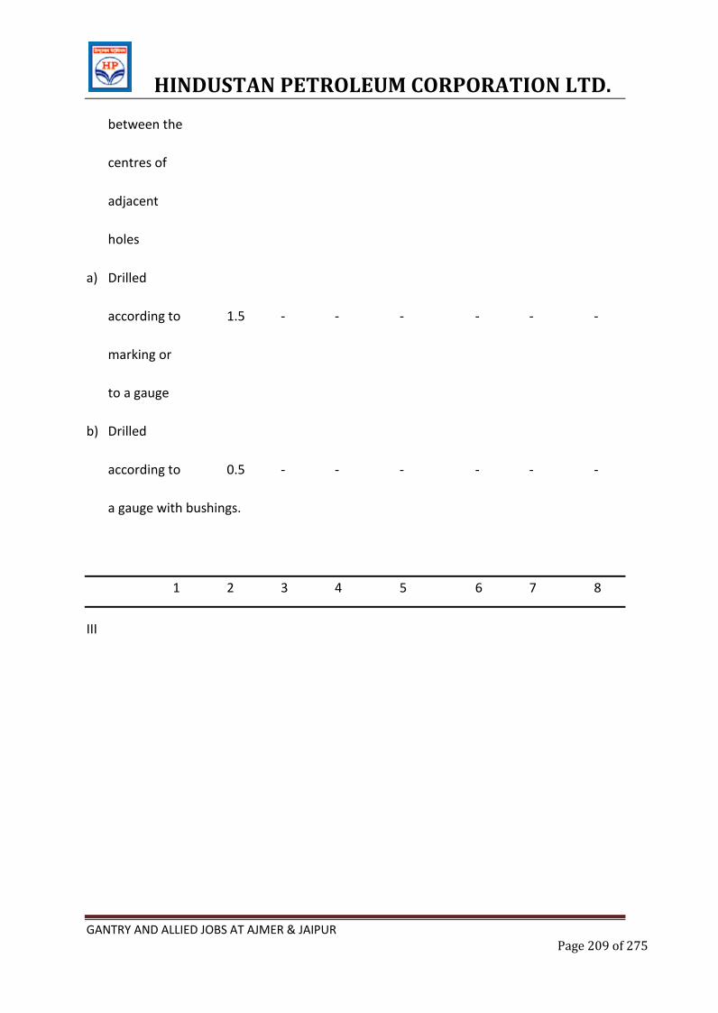
HINDUSTAN PETROLEUM CORPORATION LTD.
GANTRY AND ALLIED JOBS AT AJMER & JAIPUR Page 209 of 275
between the
centres of
adjacent
holes
a) Drilled
according to 1.5 - - - - - -
marking or
to a gauge
b) Drilled
according to 0.5 - - - - - -
a gauge with bushings.
1 2 3 4 5 6 7 8
III
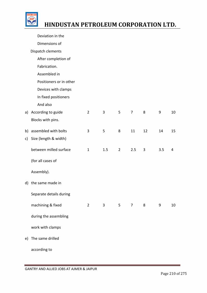
HINDUSTAN PETROLEUM CORPORATION LTD.
GANTRY AND ALLIED JOBS AT AJMER & JAIPUR Page 210 of 275
Deviation in the
Dimensions of
Dispatch clements
After completion of
Fabrication.
Assembled in
Positioners or in other
Devices with clamps
In fixed positioners
And also
a) According to guide 2 3 5 7 8 9 10
Blocks with pins.
b) assembled with bolts 3 5 8 11 12 14 15
c) Size (length & width)
between milled surface 1 1.5 2 2.5 3 3.5 4
(for all cases of
Assembly).
d) the same made in
Separate details during
machining & fixed 2 3 5 7 8 9 10
during the assembling
work with clamps
e) The same drilled
according to
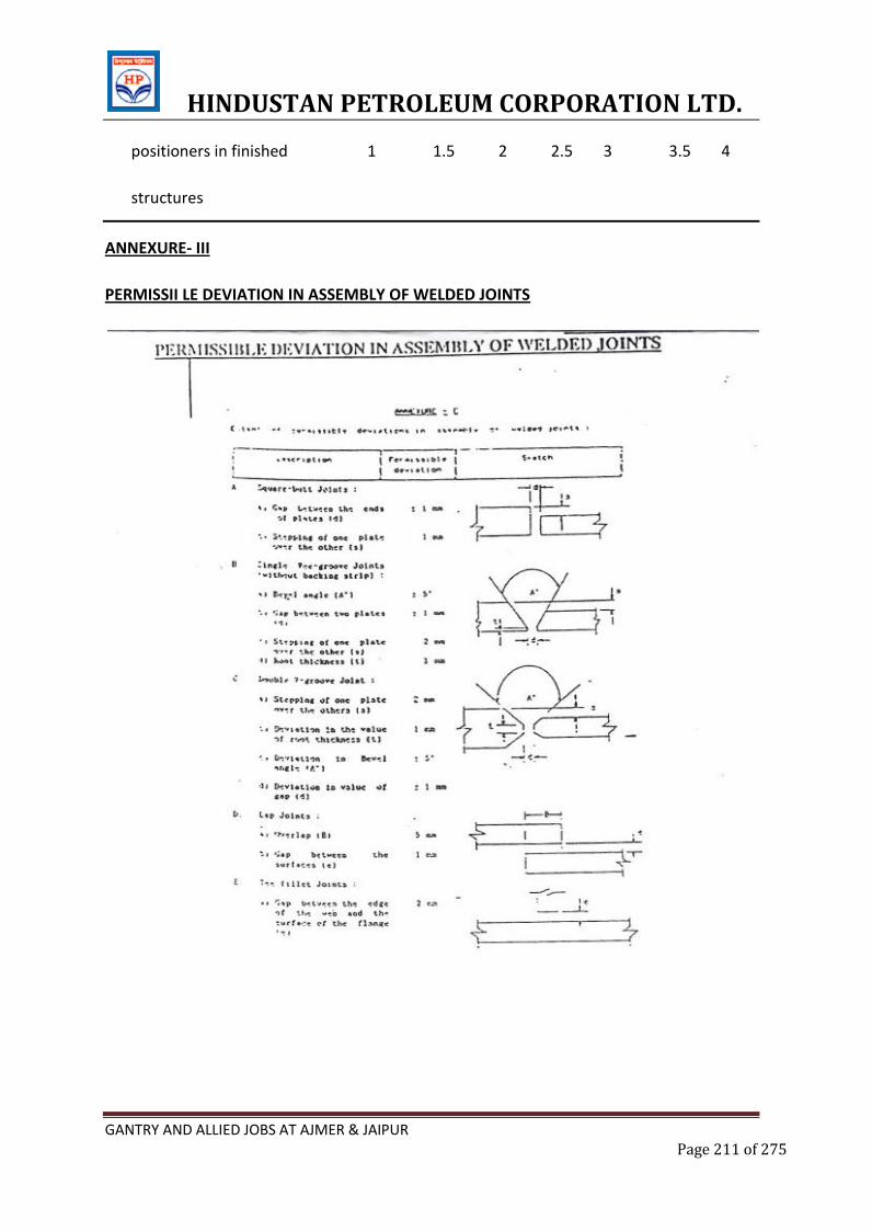
HINDUSTAN PETROLEUM CORPORATION LTD.
GANTRY AND ALLIED JOBS AT AJMER & JAIPUR Page 211 of 275
positioners in finished 1 1.5 2 2.5 3 3.5 4
structures
ANNEXURE- III
PERMISSII LE DEVIATION IN ASSEMBLY OF WELDED JOINTS

HINDUSTAN PETROLEUM CORPORATION LTD.
GANTRY AND ALLIED JOBS AT AJMER & JAIPUR Page 212 of 275
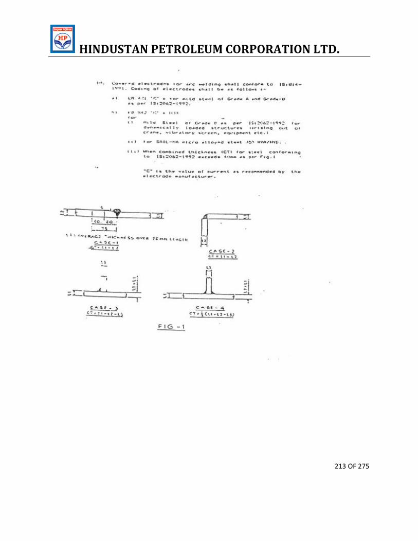
HINDUSTAN PETROLEUM CORPORATION LTD.
213 OF 275
HINDUSTAN PETROLEUM CORPORATION LTD.
214 OF 275
ANNEXURE-IV
COLUMNS
1 Deviation of column axis at foundation top
Level with respect to true axis
In longitudinal dir +/- 5 mm
n Lateral dir +/- 5 mm
2. Deviation in the level of bearing surface of
Columns at foundation top wrp to true level +/- 5 mm
3. Out of plumb ness of column axis from true
Vertical axis and measured at column top
For columns with out any special requirement
Up to and including 30 m +/- H/1000 or +/-25 mm which
Ever is less
Over 30 m ht +/-H/1200 or +/- 35 mm(less)
For columns with special reg like cranes
Or such similar requirement
Up to and including 30 m +/- H/1000 or +/-20 mm which
Ever is less
HINDUSTAN PETROLEUM CORPORATION LTD.
215 OF 275
Over 30 m ht +/-H/1500 or +/- 25 mm(less)
4. Deviation in straightness in Long & +/- H/1000 or +/-10mm (less)
Traverse direction of columns at any point
Along the height
5. Diff in the erected position of adjacent pairs +/-5mm
Of columns along length or across width of
Building prior to connecting trusses/beams
With respect to true distance.
6. Deviation in any bearing or seating level +/-5 mm
With respect to true level
NOTE: i) Tolerance specified under 3(a) and 3(b) should be read in conjunction with 4 and 5
ii) “H” above is the column height in mm.
13. TRUSSES
1. Shift. At the centre of top chord member + 1/250 of height span in mm or Truss
with
Respect to the centre of span or + 15 mm whichever is less
Vertical plane passing through the centre
HINDUSTAN PETROLEUM CORPORATION LTD.
216 OF 275
Of Bottom chord.
2. Lateral shift of top chord at the centre of of
Truss span from the vertical + 1/1500 of span of truss in plane
passing through the centre of mm or + 10mm whichever
Supports of the truss. is less
.
3. Lateral shift in location of truss from its true
Vertical position + 10
4. Lateral shift in location of purlins from + 5
True position
5. Deviation in difference of bearing levels L/1200 or 20 mm whichever of trusses or
beam from the true is less
(L = span) difference.
NOTES:-
1. The tolerances specified do not apply to steel structures where deviation from true
positions are intimately linked with or directly influence the technological process. In such
cases. The tolerances on erected steel structures shall be as per recommendations of
process technologists / equipment suppliers.
HINDUSTAN PETROLEUM CORPORATION LTD.
217 OF 275
2. The observed or calculated values of deviations of steel structures from their true positions
shall be rounded off in accordance with IS: 2-1960 for comparison with permissible
tolerances specified in this table. The number of significant places retained in the rounded-
off value should be same as that specified in this table.
ANNEXURE-V
PAINTING SYSTEM
A. Surface preparation: Sa 2 ½ according to Swedish standard SIS 055900
1. First Coat (Primer) : Epilux FRX anti corrosive primer
75 microns DFT
2. Second coat (Intermediate) : Epilux 950 Super High Build 150
Microns DFT
3. Finish Coat (Finishing) : Epilux 950 Super High Build 150
microns DFT
Total Thickness : 375 Microns
Painting system for walkways
1 Primer : One coat of Epilux FRX primer – 75 microns
DFT.
HINDUSTAN PETROLEUM CORPORATION LTD.
218 OF 275
2. Finish : One coat of 1x150-Epilux 555 CTE HB
ANNEXURE -VI
MATERIAL OF CONSTRUCTION (AS APPLICABLE)
1. Unless otherwise specified in the drawing:
All rolled sections and plates shall conform to Grade-A as per IS:2062.1992.
2. Plated structures subjected to dynamic loading shall conform to Grade-B as per
15:2062-1992.
3. High strength micro-alloyed steel shall conform to SAIL-MA 350 HYA/HYB (SAIL
product).
4. Steel sheets shall conform to IS:1079-1988.
5. Steel tubes for structural purposes shall conform to 15:1161 1979 (Grade YST-
240).
6. deleted
7. Gutter and down Corner shall be of copper bearing steel conforming to IS : 2062 –
1992.
8. Crane rails shall conform to IS : 3443 – 1980.
9. Glazing shall be 6 mm thick rough cast wired glass as per IS:3548 .1988.
10. All black hexagonal bolls, nuts and locknuts shall conform to 1S:1363-1984 and
IS:1364 1983 (for precision and semi-precision hexagonal bolts). Washers shall
conform to IS:1148.1982:
11. All HSFG bolts shall conform to 15:3757-1985.
12. Covered electrodes for arc welding shall conform to IS:814- 1991. Coding of
electrodes shall be as follows: -
HINDUSTAN PETROLEUM CORPORATION LTD.
219 OF 275
ER 421 'C' x for mild steel of Grade A and Grade-B as per 1S:2062-1992-EB 542 'C' x
H3X for
i) Mild Steel of Grade B as per 15:2062-1992 for dynamically loaded structures (arising
out of crane, vibratory screen, equipment etc.)
ii) For SAIL-MA micro alloyed steel 350 HYAIHYB.
iii) When combined thickness (CT) for steel conforming to 15:2062-1992 exceeds 40mm
as per Fig.1
"C" is the value of current as recommended by the electrode manufacturer.
HINDUSTAN PETROLEUM CORPORATION LTD.
220 OF 275
E.6.STANDARD SPECIFICATION FOR SHOP AND FIELD PAINTING
1.0 GENERAL
1.1 These technical specifications shall be applicable for the work covered by the Contract.
It is understood that Contractor shall complete the work in all respects with best quality
materials and workmanship, best engineering practice, Manufacturer recommendations
and instructions of HPCL.
1.2 All the items covered in this specification are required to be supplied by the Contractor
only.
2.0 SCOPE
Scope of work covered in this specification shall include but not limited to the following:
1. Surface preparation for all components of A/G product tank, structural steel, and
pipelines covered in this Contract.
2. Selection, procurement and application of primers, paints and other materials on
various metallic surfaces including providing all requisite scaffolding, spray equipment,
compressors, applicators, brushes, etc.
3. Lettering, marking as per HPCL requirements.
3.0 CODES AND STANDARDS
3.1 REFERENCE STANDARDS
IS : 5
IS : 101
ASTM STANDARDS
3.2 SURFACE PREPARATION STANDARDS
HINDUSTAN PETROLEUM CORPORATION LTD.
221 OF 275
SWEDISH STANDARD : SIS-05-5900-1967/ISO-8501-1-1988
THIS STANDARD CONTAINS PHOTOGRAPHS OF THE VARIOUS STANDARDS ON FOUR
DIFFERENT DEGREES OF RUSTED STEEL.
MANUFACTURER’S BROCHURES AND INSTRUCTIONS WITH RESPECT TO STORAGE,
SURFACE PREPARATION, MIXING AND THINNING, APPLICATION AND CURING
INTERVALS.
4.0 EQUIPMENT
All tools, brushes, rollers, spray guns, abrasive materials, sand, hand/ power tools for
cleaning, scaffolding materials, air compressors, instrument for measuring humidity, etc
required for the works shall be supplied by the Contractor.
5.0 SURFACE PREPARATION, COATING APPLICATION AND DOCUMENTATION
5.1 GENERAL
5.1.1 In order to achieve the maximum durability, grit blast cleaning shall be followed.
5.1.2 Mill scale, rust, rust scale, etc. shall be fully removed by Grit blast cleaning to SA 2 ½ or
equivalent as per SWEDISH STANDARD : SIS-05-5900-1967/ISO-8501-1-1988.
5.1.3 Grit Blast cleaning shall not be performed where dust can contaminate surfaces
undergoing such cleaning or in conditions where the humidity exceeds 85%.
5.1.4 The first coat of primer must be applied on dry surface immediately and in any case
within 4 hrs of cleaning of surface.
5.1.5 Blasting and painting shall in general be avoided during unfavorable weather conditions.
5.2 PROCEDURE FOR SURFACE PREPARATION
5.2.1 GRIT BLAST CLEANING
HINDUSTAN PETROLEUM CORPORATION LTD.
222 OF 275
The surface shall be Grit blasted with Copper Slag grit at a pressure of about 7 kg/sqcm
at appropriate distance and angle using compressed air and Grit to give a white metallic
luster. Surface profile shall be uniform to provide good key for paint adhesion. Ferrous
Grit will normally be available in round shape.
5.3 COATING PROCEDURE AND APPLICATION
5.3.1 Grit blasted surface upon inspection and clearance by HPCL shall be coated with one
complete application of primer as soon as practicable and in no case later than 4 hrs on
the same day. Applied paint shall have the required Dry Film Thickness (DFT) after
drying.
5.3.2 Each coat shall be in a proper state of cure or dryness before the application of
succeeding coat. Manufacturer’s instructions shall be followed for intercoat interval.
5.3.3 The type of application may be Air spray or Airless spray or Brush application as per
manufacturer recommendation and HPCL instructions for getting satisfactory results.
5.3.4 For each coat, the painter should know the WFT corresponding to the specified DFT and
standardize the paint application technique accordingly. This has to be ensured in a
qualification trial by Contractor.
5.4 SCAFFOLDING
Approved type of scaffolding shall be used and all the painters shall be provided with
Safety belts for ensuring accident free working.
5.5 DOCUMENTATION
A written quality Plan with procedure for qualification trials and for actual work.
Daily progress Report with details of humidity, surface preparation, surface profile, Dry
film thickness particulars of applications, number of coats applied, type of materials
used, methodology-Air or Airless or Brush, progress of work vs programme.
Code and Batch numbers of primers and paint materials used.
HINDUSTAN PETROLEUM CORPORATION LTD.
223 OF 275
Type of testing equipments and their calibration.
Elcometer readings for the various components jointly recorded with HPCL.
Paint consumption statement along with the Theoretical consumption requirements.
6.0 RECOMMENDED MANUFACTURERS
ASIAN PAINTS
BERGER PAINTS
GOODLASS NEROLAC
JENSON AND NICHOLSON
SHALIMAR PAINTS
BOMBAY PAINTS
7.0 HPCL LOGO AND LETTERING
HPCL will provide their LOGO with sizing, Flow, coloring and same is to be provided to
the Tanks.
HPCL will also convey to the Contractor in writing details of the lettering for product and
tank details along with the desired color-coding and same has to be arranged by the
Contractor.
8.0 INSPECTION AND TESTING
8.1 All painting materials including primers and thinners brought to site by the Contractor
for application shall be directly procured from Approved manufacturers as per
specifications and shall be accompanied by Manufacturer Test Certificates.
8.2 HPCL may call for tests for the primers and paints including verification of batch wise
tests for physical and chemical analysis. The Contractor shall carry out the same at his
own cost and provide the results to HPCL.
8.3 The painting work shall be subjected to inspection by HPCL at all times. Stages of
inspection are as follows:
HINDUSTAN PETROLEUM CORPORATION LTD.
224 OF 275
1) Surface preparation
2) Primer application
3) Each coat of paint
All records of inspection shall be maintained in Registers and jointly signed by HPCL and
Contractor.
Any defect noticed during the various stages of inspection shall be rectified by the
Contractor to the satisfaction of HPCL before proceeding further. Irrespective of the
inspection, repair and approval at intermediate stages of work, Contractor shall be fully
responsible for making good any defects found during Final inspection or during the
Defect Liability period. DFT shall be checked and wherever shot same shall be made up
with additional coats.
8.4 The shades of successive coats should be slightly different in colour in order to ensure
application of individual coats in consultation with manufacturer.
Calibrated Digital Elcometers, surface profile gauges and any other inspection
8.5 instrument required by HPCL shall be provided by the contractor at site.
8.6 The contractor shall arrange expert technical support at site by paint Manufacturer who
will cross verify independently regarding surface preparation and DFT and quality and
provide a report to HPCL.
9.0 PRIMERS AND FINISH COATS DESIGNATIONS
PRIMERS
P-1 : HIGH BUILD EPOXY MASTIC COATING ( ONLY AT WELD JOINTS)
P-2 : INORGANIC ZINC SILICATE COATING
FINSIH COATS/ PAINTS
F-1 : HIGH BUILD MIO
HINDUSTAN PETROLEUM CORPORATION LTD.
225 OF 275
F-2 : ACRYLIC POLYURETHANE FINISH
PAINTING FOR PIPING
SL.NO. TYPE OF
PIPING
SURFACE
PREPARATION
PAINT SYSTEM TOTAL DFT
IN
MICRONS FIELD
PRIMER
FINISH PAINT
1 PRODUCT
LINE
SA 2 1/2 1 COAT OF
P-2 @ 65
MICRONS
DFT/COAT
1 COAT OF F-1 @
100 MICRONS
DFT/COAT + 2
COATS OF F-2 @ 40
MICRONS DFT/COAT
(TOTAL = 100 + 2 X
40 = 180 MIRCONS)
245
MICRONS
ALL WELD JOINTS SHALL BE BUFFED AND COATED WITH STRIPE COAT OF ZINC PHOSPHATE
PRIMER PRIOR TO TAKING UP FINISH COAT
Colour Coding shall have one band of 100mm on each side with a gap of 300mm in between.
The band shall be painted near both sides of the valves and thereafter at every 20 metres of
length of the pipeline. Extra band shall be provided wherever there is 90 deg bend in the
pipeline adjacent to the bend on one side for easy identification. The product carried shall be
written in the gap of 300mm in black letters in the flow direction and the size of the letters shall
be half the diameter of the pipelines. A 45-50mm thick x 300mm long arrow shall be painted
after each band on the pipeline in the flow direction.
Note : The finish shades of the external paints shall be as directed by HPCL Engineer-in-charge
HINDUSTAN PETROLEUM CORPORATION LTD.
226 OF 275
ATTACHMENT-I
SPECIFICATIONS FOR COPPER SLAG BLASTING :
1) The surface shall be cleaned of all dust and heavier layers of rust by copper
slag blasting the entire internal surface to photographic standard SIS: 055900-1967.
2) The consumption rate of copper slag is 1.6 Kg/Sqm of the blasted area. This has to be
ensured strictly.
3) All tools, equipments, base material, hand and power tools for cleaning, including
scaffolding material, copper slag blasting equipment, air compressor etc. shall be
arranged by the contractor at site in sufficient quantity.
4) The compressor used shall be of size enough to produce displacement of 5.6 to 7.0
Cum/Min of air at a pressure of 7 Kg/sqcm. Standard blasting equipment, hoppers,
hoses nozzles and attachments shall be used to obtain best test results and to maintain
safety standards. The rate of cleaning shall be about 15 sq.mt. per hour at a pressure of
7 kg/sq.cm.
5) The abrasive used shall be of the physical properties as mentioned below and shall be
free from oil, loan and mud etc.
6) The blast cleaned surface shall be blasted with dry compressed air before applying
primer. This should be done even if the surface appears very clean and white in colour.
The white colour may be due to deposition of silicon and reflection of light on the
surface.
7) Proper earthing and bonding arrangements shall be made to prevent any damage by
sparks produced by static electricity. Bonding shall be done between tank and blast
nozzles and hopper and air compressor also. The bonding conductor should not be less
than 16 SWG single strand copper cable.
8) The time gap between blast cleaning and application of primer shall not be more than
THREE hours. Blast cleaning work shall, commence from top to bottom.
HINDUSTAN PETROLEUM CORPORATION LTD.
227 OF 275
9) The blast cleaning operation shall be carried out keeping the nozzle at an angle of 30
degree to the vertical in order to prevent rebounding abrasive from showing down the
abrasives emerging from nozzle and from under cutting the material to be removed.
10) A blast cleaning, the percentage of bare metal obtained shall be between 95% to 100%
for each of the square meter of the blasted area corresponding to photographic visual
standards of SA 2 ½ of the Swedish standard referred above. (Pictora surface
preparation standards for painting steel surfaces).
11) Arrangements for inspection of various stages of the job shall be made available by the
Contractor so that the entire copper slag blasted area is available for inspection. Any
defective work noticed shall be immediately rectified and even re-blasting shall be done
if necessary.
12) Physical properties of Copper Slag:
a) Colour : Black
b) Grain Shape : Granulated, Angular multifaceted
c) Hardness : 5 to 7 Moh’s scale
d) Sp. Gravity : 3.2 to 3.7
e) Bulk Density : 1.87 kg/ltr.
f) Moisture Content: less than 1 %
13) Sieve Analysis of Copper Slag
Sieve Size (mm) Range
-4.0 to + 3.0 2 to 4
-3 to +2.36 3 to 12
-2.36 to +1 40 to 55
-1 to +0.5 15 to 30
-0.5 to + 0.212 6 to 12
-0.212 below 0.2 to 1.0
HINDUSTAN PETROLEUM CORPORATION LTD.
228 OF 275
E.7. SPECIFICATION FOR "MS ERW PIPES FOR PRODUCT
PIPELINES
1. Details:
MS ERW black line pipes of various sizes conforming to following specification/details:
Item : Mild steel Pipes - ERW
IN CASE THE BIDDER IS ONLY A SUPPLIER THEN, PIPES MANUFACTURED BY : MAHARASHTRA
SEAMLESS; JINDAL PIPES;PSL;WELSPUN;SURYA ROSHNI;INDUS TUBES;LALIT PROFILES;TATA
STEEL OR MAN INDUSTRIES ONLY WILL BE ACCEPTED.IN SUCH CASES,THE PIPES CARRYING
THE APPROVED MANUFACTURER’S NAME ONLY WILL BE ACCEPTED.
FURTHER, THE ENTIRE LOT OF PIPES SHALL BE SOURCED FROM A SINGLE
MANUFACTURER.COMBINATION OF DIFFERENT MANUFACTURERS WILL NOT BE ACCEPTED.
Code : All clause Nos. referred herein shall be to IS 1978 - Latest edition
(Minimum Specification) / API 5l (Grade B). In case of discrepancy,
IS Code shall prevail.
Dimensional standard : IS 1978 - Latest Edition/ API-5L
Length of each pipe : Single random 4-7 M
Ends : Bevelled with end protection caps
Marking : As per Clause no.13.3.1 of IS 1978/1982/ API-5L
2. DIMENSIONAL DETAILS:
Nominal size
( NB In mm )
Thickness / Class Grade
500 mm
450 mm
7.1 mm
7.1 mm
YST 210
YST 210
HINDUSTAN PETROLEUM CORPORATION LTD.
229 OF 275
400 mm
350 mm
300 mm
250 mm
200 mm
150 mm
100 mm
80 mm
7.1 mm
7.1 mm
7.1 mm
7.1 mm
6.4 mm
5.2 mm
4.8 mm
4.0 mm
YST 210
YST 210
YST 210
YST 210
YST 210
YST 210
YST 210
YST 210
3. SCOPE OF INSPECTION:
a. Process of Manufacture:
The ERW pipe shall be manufactured by any of the processes given in IS Code
b. Chemical requirements:
Manufacturer’s Ladle Analysis Report shall be furnished. Laddle Analysis Test Certificate
from Primary Steel Manufacturer (Supplier of HRC coils/ plates is acceptable.
Product analysis shall be carried out for each heat as per IS Code.
c. Wall thickness:
Each length of pipe shall be checked for wall thickness & same shall be recorded in
accordance to IS Code.
d. Weight:
Each length of pipe shall be weighed separately & same shall be recorded in accordance to
IS Code.
e. Straightness:
Random check to be carried out as per IS Code.
HINDUSTAN PETROLEUM CORPORATION LTD.
230 OF 275
f. Pipe ends, Workmanship & finish:
The pipe ends shall be bevel ends and provided with suitable end
protectors.
The pipes shall be provided with a suitable mill coating to prevent rusting during transit as
per IS Code.
g. Visual Inspection:
All finished pipes shall be visually examined in accordance to IS Code.
h. TESTS:
All the physical tests as detailed in Cl. 11 of IS Code as relevant for the subject pipes shall be
carried out by the Manufacturer and results furnished in accordance with IS Code.
MANUFACTURER’S TEST REPORTS SHALL BE FURNISHED.The tests shall include the
following:
1) Longitudinal tensile
2) Transverse tensile
3) Weld tensile
4) Bend test
5) Flattening test
6) Hydrostatic test-Standard pressure to be adopted.
7) Non-destructive tests
TPI shall be carried out in accordance to QAP/ITP approved by HPCL and shall include the
following:
TEST/CHECK TPI SCOPE REMARKS
WITNESS REVIEW APPROVAL
Ladle analysis Yes Yes TPI shall correlate all the
three analyses for
chemical & certify if they
Product
analysis
Yes Yes
HINDUSTAN PETROLEUM CORPORATION LTD.
231 OF 275
Mill Control
Product
analysis
Yes Yes are within variations
permitted by IS Code.
Wall thickness 10% 100% Yes
Weight 10% 100% Yes
Straightness 10% Random
as per IS
Code
Yes
Pipe ends 10% ----------- Yes Check for end protectors
Finish 100% ----------- Yes Check for mill coating
Visual
inspection
100% ----------- Yes
Physical tests
Longitudinal
tensile
----------- 100% Yes
Review of MTC Only
Transverse
tensile
----------- 100% Yes
Weld tensile ----------- 100% Yes
Bend ----------- 100% Yes
Flattening ----------- 100% Yes
NDT ----------- 100% Yes
Hydrostatic ----------- 100% Yes
Marking 10% 100% Yes
NOTE:Laddle Analysis Test Certificate from Primary Steel Manufacturer (Supplier of
HRC coils/ plates is acceptable.
HINDUSTAN PETROLEUM CORPORATION LTD.
232 OF 275
NOTE: In case the tests are required to be carried out in an external lab, then the cost
of such tests shall be borne by the Supplier only.
i. All pipes shall be stamped/marked by the 3rd party inspection agency. All test reports in
original shall be submitted to HPCL despatch location and no pipe shall be despatched
without obtaining approval from third party inspection agency.
j. Third party inspection agency shall correlate the documents as approved in QAP and
endorse the same during inspection.
HINDUSTAN PETROLEUM CORPORATION LTD.
233 OF 275
E.8.TECHNICAL SPECIFICATION FOR PIPE FITTINGS
TECHNICAL SPECIFICATIONS FOR BUTT WELDED FITTINGS
1.0 General
1.1 Chemical composition, physical properties, tests, dimensions and tolerances, heat
treatment and markings shall confirm to the applicable latest
codes/standards/specifications as specified in this document. Any deviations shall be
clearly highlighted on a separate sheet by the vendor in the Unpriced Part/Bid itself.
1.2 Test report shall be supplied for all mandatory tests as per the relevant material
specifications. Test report shall also be furnished for any supplementary test as specified
in this Document. Material test certificates (physical properties, chemical composition
and Heat treatment report) shall also be furnished for the fittings supplied.
1.3 All fittings shall be seamless/welded in construction as per Schedule of Rates. If fittings
are specified as welded, the same shall conform to clause 1.7. Seamless fittings can be
supplied in place of welded fittings with maximum negative tolerance of 0.3mm (max)
on wall thickness. Welded fittings shall not be accepted in place of seamless fittings.
1.4 Outside diameters and wall thickness (unless otherwise mentioned) of butt welded
fittings shall be in accordance with ASME B36.10 and ASME B36.19 as applicable.
1.5 For reducing butt weld fittings having different wall thickness at each end, the greater
wall thickness of the fitting shall be employed and inside bore at each end shall be
matched with the specified inside diameter.
1.6 Bevel ends details of all fittings shall conform to ANSI B16.25. Control of bevel ends shall
be as per follows:
Material
Wall Thickness
Weld Contour
Carbon Steel
Upto 22mm
Fig. 2 Type A
HINDUSTAN PETROLEUM CORPORATION LTD.
234 OF 275
Carbon Steel
Above 22mm
Fig. 3 Type A
1.7 Welded fittings:
1.7.1 All welded fittings shall be double welded. Inside weld projection shall not exceed
1.6mm. Weld shall be ground smooth at least 25mm from the ends.
1.7.2 For fittings made out of welded pipe, the welded pipe shall be double welded type and
shall be manufactured with the addition of filler metal.
1.7.3 Welded tees shall not be of fabricated (stub-in) type.
1.7.4 All welded fittings shall be normalized and radiographed by X-ray on all welds made by
fittings manufacturers and also on the parent materials.
1.7.5 Welded pipes employed for manufacture of fittings shall be made by automatic welding
only.
1.7.6 All welded carbon steel fittings shall have maximum negative tolerance of 0.3mm.
1.7.7 Specified heat treatment for carbon steel fittings shall be carried out again after weld
repairs.
1.8 Thickness/schedule lower or higher than specified shall not be accepted.
1.9 The gasket contact surfaces of stub ends shall be flat with face finish specified in the
requisition. Interpretation on the specified face finish is as follows :
Serrated Finish: Serration with 250 to 500 in AARH
Smooth Finish / 125 AARH: Serration with 125 to 250 in AARH
1.10 Seamless stub ends shall not have any welds on the body.
1.11 Special fittings like weldolet, soccolet, etc., which are not covered in ASME, MSS-SP and
this standard shall be as per manufacturer’s standard. Contours of these fittings shall
meet the requirements of ASME B31.3. Manufacturer shall submit drawings/catalogues
of these items along with the offer.
HINDUSTAN PETROLEUM CORPORATION LTD.
235 OF 275
1.12 All seamless pipes employed for manufacturing of fittings shall be required to have
undergone hydro test to ASTM A530. Welded pipes employed for manufacture of
fittings shall be tested as given below :
Welded Pipe Employed for Manufacture of Welded Fittings
Test Criteria
ASTM A671 Gr. C65,70 (C1, 32) ASTM A672 Gr. C60, 65,70 (C1, 12, 22) ASTM A671 Gr. CF60, 70, 66 (C1, 32) ASTM A691 Gr. ½ Cr, 1Cr., 1 ¼ Cr., 2 ¼ Cr., 5Cr., 9Cr (C1, 42)
P = 2ST/D T = Nom wall thickness D= OD of pipe
API 5L ASTM A358 TP304, 304L, 304H, 318, 318L, 318H, 321, 347 (C1.1 3, 4)
P = 2ST/D S=85% of SMYS T = Nom wall thickness D= OD of pipe
ASTM B725
ASTM B725
ASTM B517
ASTM B517
ASTM B514
ASTM B514
1.13 The bevel ends of all butt weld fittings shall undergo 100% MP/DP test.
1.14 Abbreviations for ends of swages and nipples shall be as follows :
BBE : Bevel both ends
PBE : Plain both ends
TBA : Threaded both ends
TOE : Threaded one ends
TSE : Threaded small ends
TLE : Threaded Large ends
HINDUSTAN PETROLEUM CORPORATION LTD.
236 OF 275
2.0 Marking and Despatch
2.1 All items shall be legibly and conspicuously stamped in accordance with the
requirements of applicable standards along with special condition like “IBR”, “Cryo”,
“NACE”, etc.
2.2 Steel die marking with round bottom punch may be permitted on body of butt weld CS
and lower alloy steel fittings.
2.3 Paint or ink for marking shall not contain any harmful metal or metal salts such as zinc,
lead or copper which cause corrosive attack on heating.
2.4 All items shall be dry, clean and free from moisture, dirt and loose foreign materials of
any kind.
2.5 All items shall be protected from rust, corrosion and mechanical damage during
transportation, shipment and storage.
2.6 Rust preventive on machined surface to be welded shall be easily removable with a
petroleum solvent, and the same shall not be harmful to welding.
2.7 Fittings under IBR, Cryo, NACE shall be painted in red, light purple and canary yellow
stripes respectively for easy identification. Width of the stripe shall be 25mm.
2.8 Each end of fitting shall be protected with a wood, metal or plastic cover.
2.9 Each size of fittings shall be supplied in separate packaging marked with the purchase
order number, item code number, material specification, size and
schedule/thickness/rating.
3.0 INSPECTION AND TESTING
4.0 The manufacturer shall perform all inspections and tests as per requirements of this
specifications and relevant codes, prior to shipment at his works. Such inspections and tests
shall be, but not limited to the following
Visual inspection
Dimensional check
Chemical composition, mechanical properties and hardness examination
HINDUSTAN PETROLEUM CORPORATION LTD.
237 OF 275
100% radiography of welds/ Ultrasonic testing for laminations( laminations more than
6.35mm shall be acceptable)
All other tests which are not specifically mentioned but are required as per applicable
standards/specifications
5.0 The purchaser’s inspector may also perform stage wise inspection as per scope given
below or as per requirements of this specification at manufacturer’s work place prior to
shipment. Manufacturer shall give reasonable notice of time and shall provide without
charge reasonable access and facilities required for inspection to the purchaser’s
inspector. Inspection and tests performed/witnessed by the purchaser’s inspector shall
in no way relieve the manufacturer’s obligation t perform the required inspection and
tests.
E.8.1
TECHNICAL SPECIFICATIONS FOR SLIP ON / BLIND FLANGES
--------------------------------------------------
DIMENSIONAL DETAILS:
-------------------------------------------------------------------------------------
ITEM SIZE (MM) THICKNESS
NO. (DIA) (MM)
----------------------------------------------------------------------------------------
A. SLIP ON FLANGE
-----------------------------------------------------------------------------------------
1. 600 48.0
2. 500 43.0
3. 450 39.7
4. 400 36.6
5. 350 35.1
6. 300 31.8
HINDUSTAN PETROLEUM CORPORATION LTD.
238 OF 275
7. 250 30.2
8. 200 28.6
9. 150 25.4
10. 100 23.9
11. 80 23.9
12. 50 19.1
B. BLIND FLANGE
-----------------------------------------------------------------------
1. 600 48.0
2. 500 43.0
3. 450 39.7
4. 400 36.6
5. 350 35.1
6. 300 31.8
7. 250 30.2
8. 200 28.6
9. 150 25.4
10. 100 23.9
11. 80 23.9
12. 50 19.1
TECHNICAL SPECIFICATION FOR FLANGES
1. Specification : Conforming to ASA Class 150 raised face without neck.
2. Material : MS plates conforming to IS: 226/IS: 2062 Gr A
3. Dimensions & : As per ANSI B.16.5
Holes drilled
HINDUSTAN PETROLEUM CORPORATION LTD.
239 OF 275
4. Rating : 150 psi
5. Face : Raised with serrations.Both faces shall be turned Smooth before
fabrication.
6. Bolt holes : All bolt holes shall saddle The centre line.
The third party inspection shall be carried out by the approved agency:
The following inspection shall be carried out by the 3rd party:
a) Visual Inspection
b) Dimension check
All (100%) Flanges shall be inspected by the 3rd party.
E.8.2.TECHNICALSPECIFICATIONS FOR FORGED BENDS ,EQUAL& UNEQUAL TEES
AND CONCENTRIC REDUCERS.
SCOPE:
Forged 90 deg.(1.5D) and 45 deg. bends and concentric reducers of SCH 40 thickness with
bevelled ends conforming to ANSI B 16.9. Material for the fittings shall conform to ASTM A-234
Grade WPB.
Inspection by approved Third Party Inspection agency
Scope of inspection shall include the following:
Fittings shall be inspected for dimensional accuracy, uniform surface, edge preparation, bevel
angle etc. They shall be within permissible limits specified in the relevant standards.
Hydrostatic test certificate of pipe used for making the bends to be submitted and verified at
the time of third party inspection.
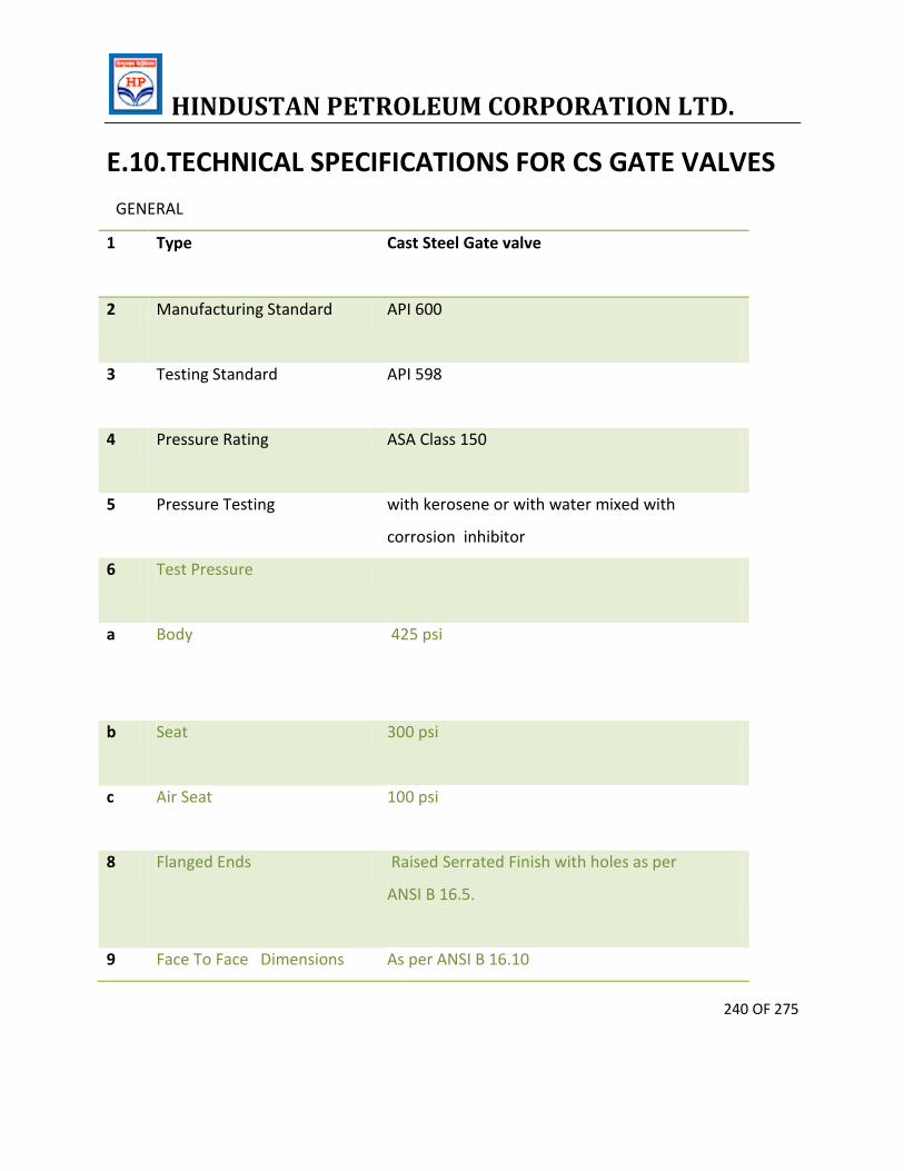
HINDUSTAN PETROLEUM CORPORATION LTD.
240 OF 275
E.10.TECHNICAL SPECIFICATIONS FOR CS GATE VALVES
GENERAL
1 Type Cast Steel Gate valve
2 Manufacturing Standard API 600
3 Testing Standard API 598
4 Pressure Rating ASA Class 150
5 Pressure Testing with kerosene or with water mixed with
corrosion inhibitor
6 Test Pressure
a Body
425 psi
b Seat 300 psi
c Air Seat 100 psi
8 Flanged Ends Raised Serrated Finish with holes as per
ANSI B 16.5.
9 Face To Face Dimensions As per ANSI B 16.10
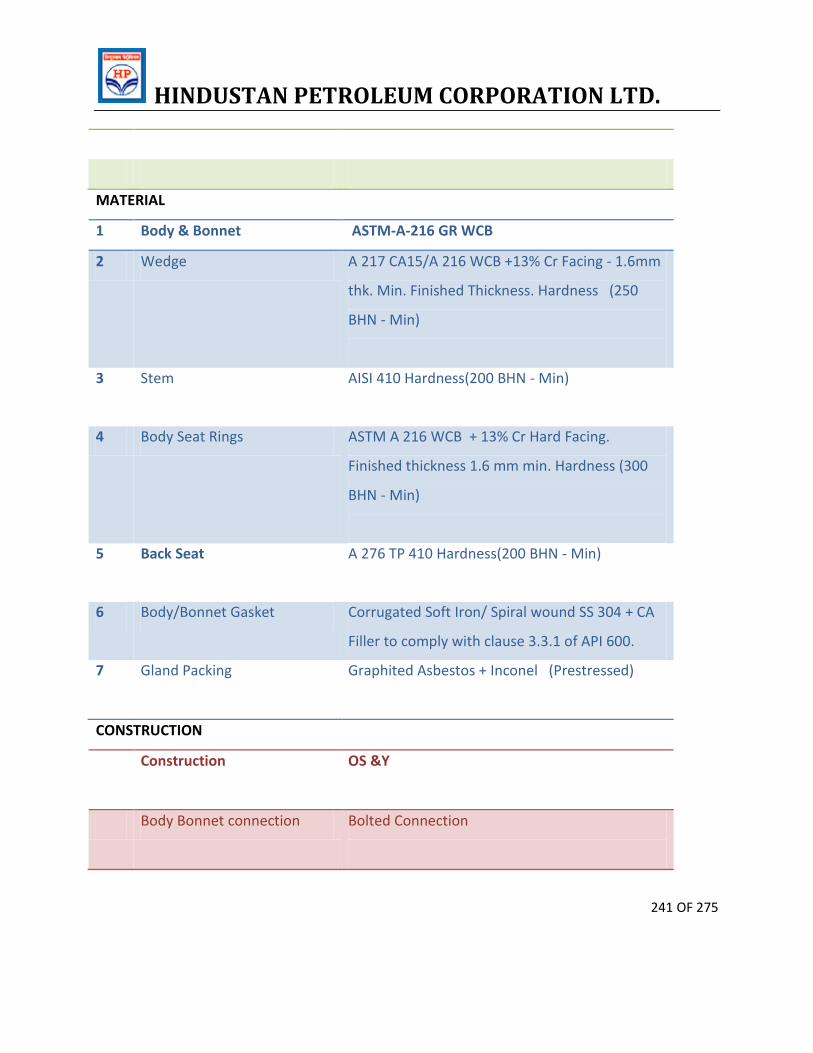
HINDUSTAN PETROLEUM CORPORATION LTD.
241 OF 275
MATERIAL
1 Body & Bonnet ASTM-A-216 GR WCB
2 Wedge A 217 CA15/A 216 WCB +13% Cr Facing - 1.6mm
thk. Min. Finished Thickness. Hardness (250
BHN - Min)
3 Stem AISI 410 Hardness(200 BHN - Min)
4 Body Seat Rings ASTM A 216 WCB + 13% Cr Hard Facing.
Finished thickness 1.6 mm min. Hardness (300
BHN - Min)
5 Back Seat A 276 TP 410 Hardness(200 BHN - Min)
6 Body/Bonnet Gasket Corrugated Soft Iron/ Spiral wound SS 304 + CA
Filler to comply with clause 3.3.1 of API 600.
7 Gland Packing Graphited Asbestos + Inconel (Prestressed)
CONSTRUCTION
Construction OS &Y
Body Bonnet connection Bolted Connection
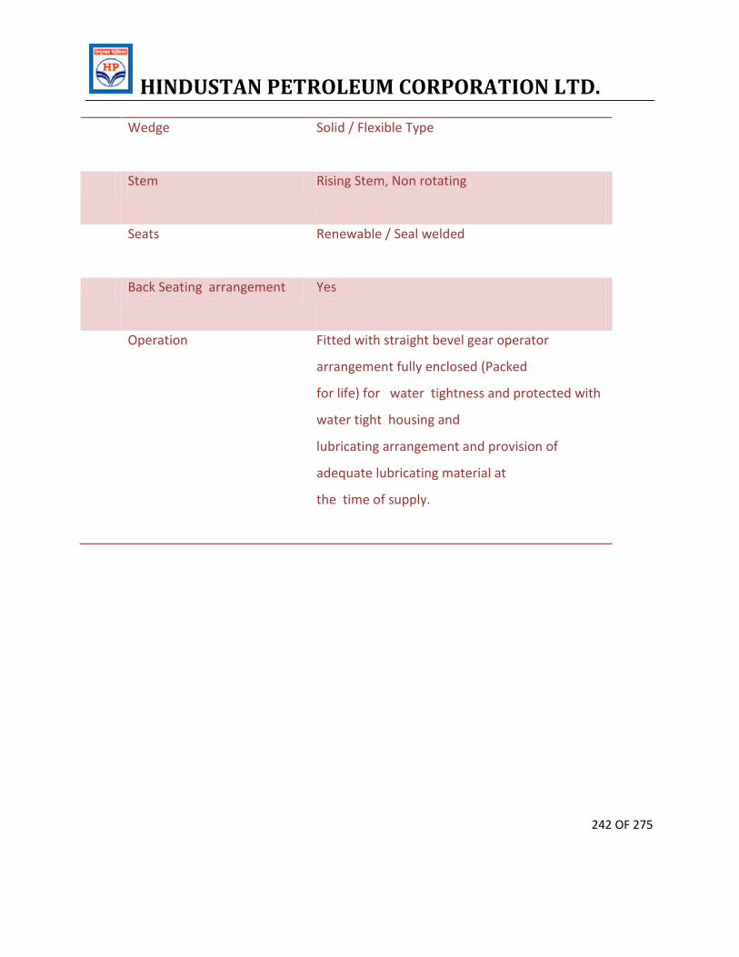
HINDUSTAN PETROLEUM CORPORATION LTD.
242 OF 275
Wedge Solid / Flexible Type
Stem Rising Stem, Non rotating
Seats Renewable / Seal welded
Back Seating arrangement Yes
Operation Fitted with straight bevel gear operator
arrangement fully enclosed (Packed
for life) for water tightness and protected with
water tight housing and
lubricating arrangement and provision of
adequate lubricating material at
the time of supply.
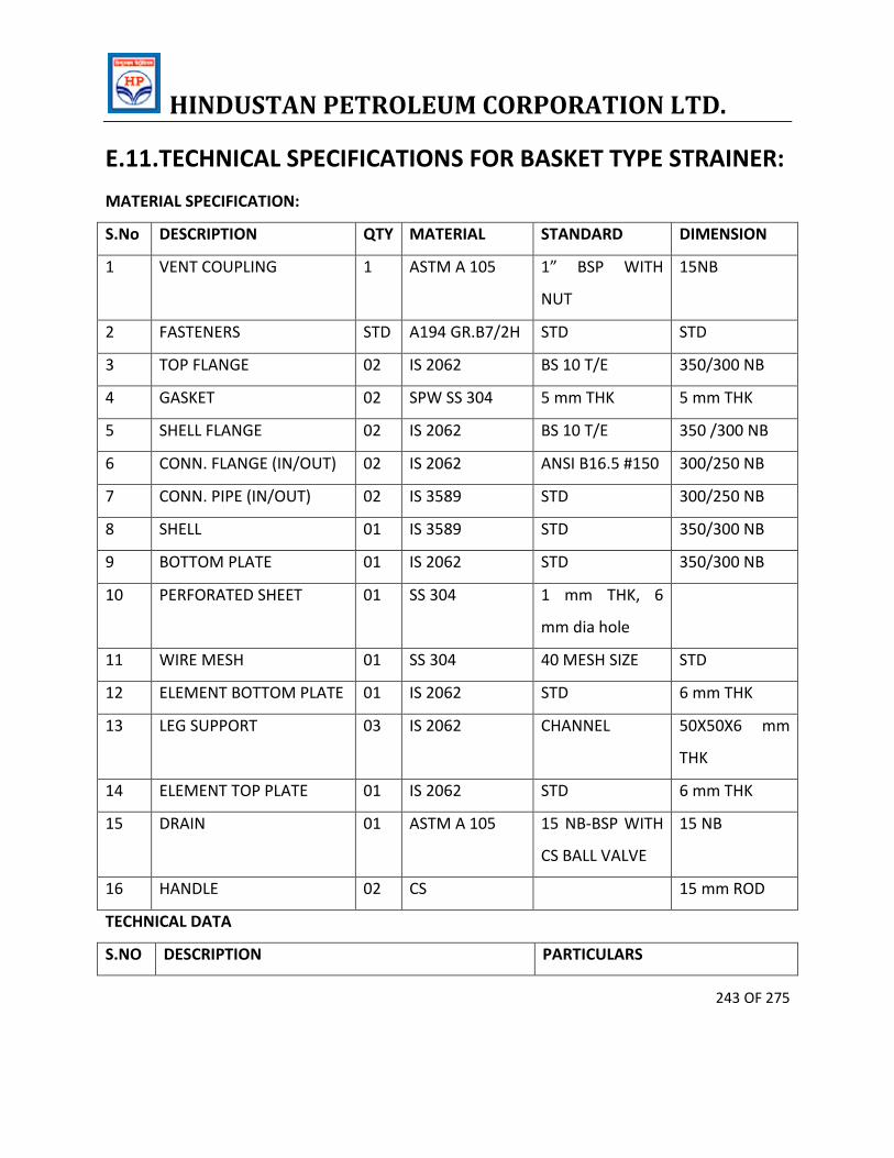
HINDUSTAN PETROLEUM CORPORATION LTD.
243 OF 275
E.11.TECHNICAL SPECIFICATIONS FOR BASKET TYPE STRAINER:
MATERIAL SPECIFICATION:
S.No DESCRIPTION QTY MATERIAL STANDARD DIMENSION
1 VENT COUPLING 1 ASTM A 105 1” BSP WITH
NUT
15NB
2 FASTENERS STD A194 GR.B7/2H STD STD
3 TOP FLANGE 02 IS 2062 BS 10 T/E 350/300 NB
4 GASKET 02 SPW SS 304 5 mm THK 5 mm THK
5 SHELL FLANGE 02 IS 2062 BS 10 T/E 350 /300 NB
6 CONN. FLANGE (IN/OUT) 02 IS 2062 ANSI B16.5 #150 300/250 NB
7 CONN. PIPE (IN/OUT) 02 IS 3589 STD 300/250 NB
8 SHELL 01 IS 3589 STD 350/300 NB
9 BOTTOM PLATE 01 IS 2062 STD 350/300 NB
10 PERFORATED SHEET 01 SS 304 1 mm THK, 6
mm dia hole
11 WIRE MESH 01 SS 304 40 MESH SIZE STD
12 ELEMENT BOTTOM PLATE 01 IS 2062 STD 6 mm THK
13 LEG SUPPORT 03 IS 2062 CHANNEL 50X50X6 mm
THK
14 ELEMENT TOP PLATE 01 IS 2062 STD 6 mm THK
15 DRAIN 01 ASTM A 105 15 NB-BSP WITH
CS BALL VALVE
15 NB
16 HANDLE 02 CS 15 mm ROD
TECHNICAL DATA
S.NO DESCRIPTION PARTICULARS
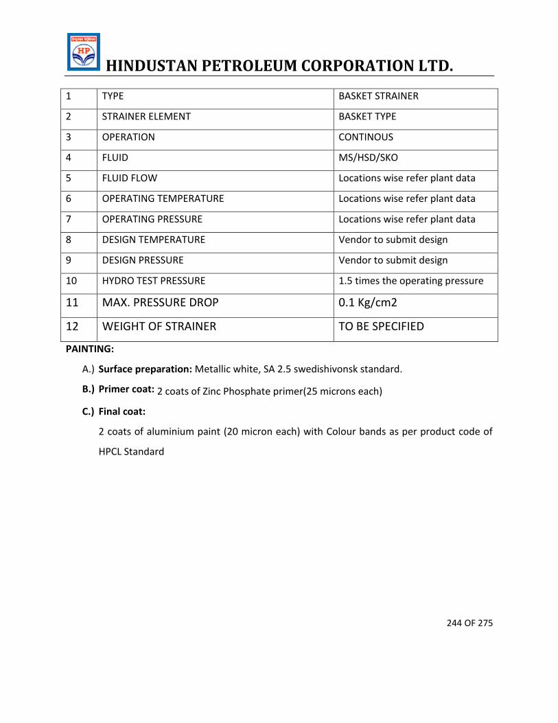
HINDUSTAN PETROLEUM CORPORATION LTD.
244 OF 275
1 TYPE BASKET STRAINER
2 STRAINER ELEMENT BASKET TYPE
3 OPERATION CONTINOUS
4 FLUID MS/HSD/SKO
5 FLUID FLOW Locations wise refer plant data
6 OPERATING TEMPERATURE Locations wise refer plant data
7 OPERATING PRESSURE Locations wise refer plant data
8 DESIGN TEMPERATURE Vendor to submit design
9 DESIGN PRESSURE Vendor to submit design
10 HYDRO TEST PRESSURE 1.5 times the operating pressure
11 MAX. PRESSURE DROP 0.1 Kg/cm2
12 WEIGHT OF STRAINER TO BE SPECIFIED
PAINTING:
A.) Surface preparation: Metallic white, SA 2.5 swedishivonsk standard.
B.) Primer coat: 2 coats of Zinc Phosphate primer(25 microns each)
C.) Final coat:
2 coats of aluminium paint (20 micron each) with Colour bands as per product code of
HPCL Standard
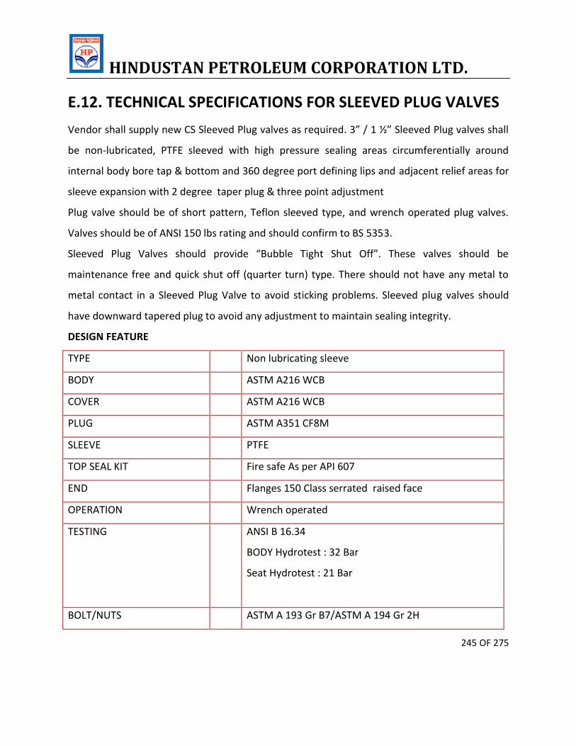
HINDUSTAN PETROLEUM CORPORATION LTD.
245 OF 275
E.12. TECHNICAL SPECIFICATIONS FOR SLEEVED PLUG VALVES
Vendor shall supply new CS Sleeved Plug valves as required. 3” / 1 ½” Sleeved Plug valves shall
be non-lubricated, PTFE sleeved with high pressure sealing areas circumferentially around
internal body bore tap & bottom and 360 degree port defining lips and adjacent relief areas for
sleeve expansion with 2 degree taper plug & three point adjustment
Plug valve should be of short pattern, Teflon sleeved type, and wrench operated plug valves.
Valves should be of ANSI 150 lbs rating and should confirm to BS 5353.
Sleeved Plug Valves should provide “Bubble Tight Shut Off”. These valves should be
maintenance free and quick shut off (quarter turn) type. There should not have any metal to
metal contact in a Sleeved Plug Valve to avoid sticking problems. Sleeved plug valves should
have downward tapered plug to avoid any adjustment to maintain sealing integrity.
DESIGN FEATURE
TYPE Non lubricating sleeve
BODY ASTM A216 WCB
COVER ASTM A216 WCB
PLUG ASTM A351 CF8M
SLEEVE PTFE
TOP SEAL KIT Fire safe As per API 607
END Flanges 150 Class serrated raised face
OPERATION Wrench operated
TESTING ANSI B 16.34
BODY Hydrotest : 32 Bar
Seat Hydrotest : 21 Bar
BOLT/NUTS ASTM A 193 Gr B7/ASTM A 194 Gr 2H
HINDUSTAN PETROLEUM CORPORATION LTD.
246 OF 275
ENDS SHOULD HAVE RAISED FLANGES CONFORMING TO ASA 150 CLASS WITH HOLES DRILLED
AS PER ANSI-B-16.5
WORKING PRESSURE 150 PSI
CS WRENCHES: Operating wrenches suitable for operating this type of valves.
THIRD PARTY INSPECTION by approved agency
All Valves (100 %) shall be tested by manufacturer's quality control officials, before offering the
valves for inspection.
All test certificates for material conformance and pressure test shall be verified and endorsed
by the third party inspection agency.
Testing procedure shall confirm to API-598. / BS 6755 -PART-I
The following tests will be witnessed by the third party inspection agency
a) Hydraulic shell test.-100 % Valves.
b) High pressure closure test -10 % Valves selected at random in one batch. (Minimum of TWO
Valves to be tested)
c) Low pressure closure test on 10% valves selected at random in one batch. (Minimum of TWO
Valves to be tested)
In addition they shall also do the following:-
a) Overall dimensional check on assembled valves for conformance with
drawings/specifications.
b) Identification against Manufacturer's test certificates.
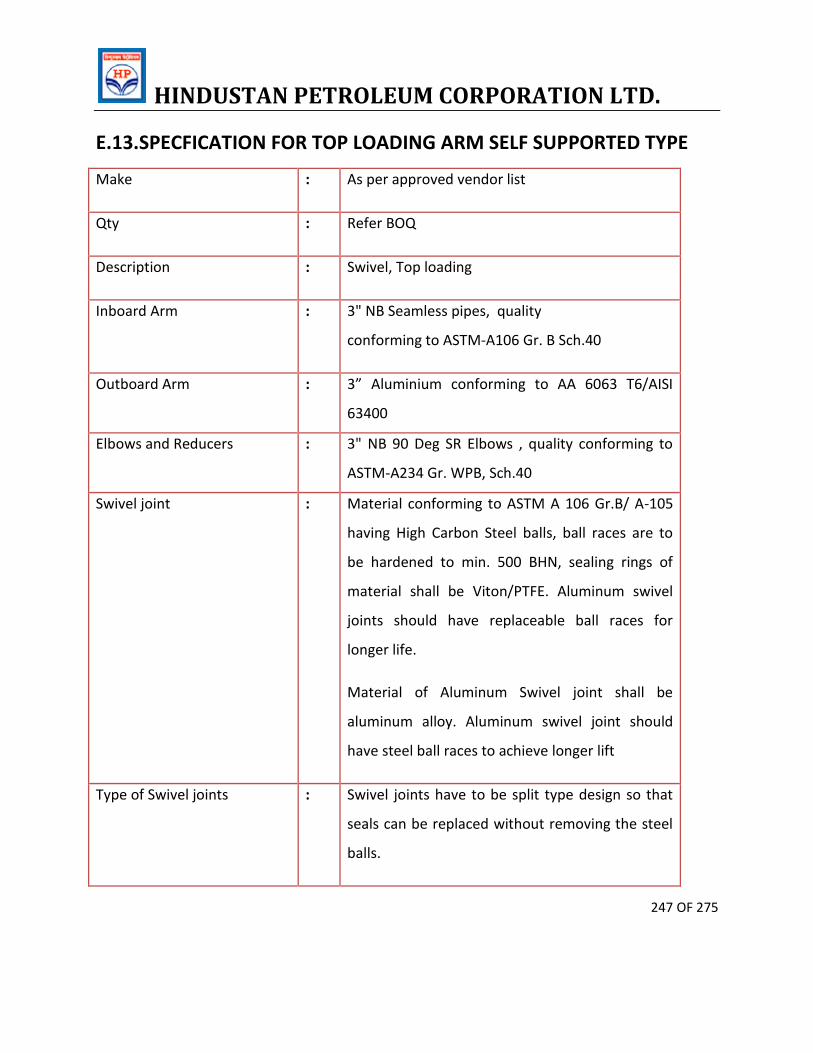
HINDUSTAN PETROLEUM CORPORATION LTD.
247 OF 275
E.13.SPECFICATION FOR TOP LOADING ARM SELF SUPPORTED TYPE
Make : As per approved vendor list
Qty : Refer BOQ
Description : Swivel, Top loading
Inboard Arm : 3" NB Seamless pipes, quality
conforming to ASTM-A106 Gr. B Sch.40
Outboard Arm : 3” Aluminium conforming to AA 6063 T6/AISI
63400
Elbows and Reducers : 3" NB 90 Deg SR Elbows , quality conforming to
ASTM-A234 Gr. WPB, Sch.40
Swivel joint : Material conforming to ASTM A 106 Gr.B/ A-105
having High Carbon Steel balls, ball races are to
be hardened to min. 500 BHN, sealing rings of
material shall be Viton/PTFE. Aluminum swivel
joints should have replaceable ball races for
longer life.
Material of Aluminum Swivel joint shall be
aluminum alloy. Aluminum swivel joint should
have steel ball races to achieve longer lift
Type of Swivel joints : Swivel joints have to be split type design so that
seals can be replaced without removing the steel
balls.
HINDUSTAN PETROLEUM CORPORATION LTD.
248 OF 275
Aluminum drop pipe : (73 mm OD x 63 mm ID) Aluminum pipe of 1000
mm long with tapered end on one side & other
side screwed.
Spring Balancing System : Quality conforming to IS: 1239. Helical Spring box
with spring of material conforming to EN 47/45.
Inlet Flanges : Raised face serrated finish, ASA class 150, with
holes drilled according to ANSI B 16.5 face to face
as per ANSI B 16.1 made of ASTM A 105 material
Intermediate Flanges : Flanges other than inlet flanges in the loading arm
shall have dimensions as per TTMA & will be
made of IS 2062 & aluminum alloy.
Balancing : Spring Type (Torsion / Compression)
Design Pressure : 15 Kg/ sq.cm
Working Pressure : 2-8 Kg/Sq cm
Hydrostatic Test Pressure : 15 Kg/ Sq Cm
Operating Temp : 0 - 50 deg.C
End connections : 3" ANSl 150# WNRF FLANGED
Seals : Viton
Working envelope : Reach 3 - 4 mtr.(Typical). 4 mtr. X 6 mtr. X 1
mtr.(Vertical)
HINDUSTAN PETROLEUM CORPORATION LTD.
249 OF 275
Vacuum Breaker : ½” integral viton Diaphragm type with SS nipple.
It shall be at the apex of the system where
vacuum is generated
Filling Position locking
Arrangement
: A suitable locking arrangement for the outboard
arm shall be provided to prevent jerking action of
Loading Arm as well as lock the outboard arm at
the operation desired position while filling
tankers.
Locking chain shall be provided
Parking Lock : A suitable locking arrangement for the inboard
arm shall be provided to lock the loading arm in
parking position so that it remains in parking
place. Lock should be spring loaded so that
locking in parking place is automatic & should be
easy to operate.
Loading Arm type : Self-supported Top Loading. Quantity for Left
hand type & Right hand type shall be as per
individual location requirement.
Inlet Pipe entry : To suit the site condition
DESIGN REQUIREMENT
1. Loading Arm shall be self-supported type. Extra bearing support which creates
obstruction to the movement of manpower & other equipment should not to be
HINDUSTAN PETROLEUM CORPORATION LTD.
250 OF 275
required by the Loading Arm i.e. Design of Loading arm should be such that it do not
require any extra Bearing support.
2. Base swivel joint should be capable of taking bending load of the loading arm. Loading
shall be checked of bending load by applying 40 Kg weight at the end of inboard arm
and will be checked for smooth rotation.
3. Swivel Joint should be offered for Cycle testing of 20000 Oscillations of Min. 270 degree
and should be checked for pressure testing at 10 Kg under rotation after the same.
4. The swivel joints shall be designed to make the loading arm maneuverable with
minimum effort. All swivel joint should be of split type design and have minimum type
rows of chrome steel hardened balls fixed in suitably hardened carbon steel guide ways.
Material conforming to ASTM A 106 Gr. B/A-105 having HCS Balls, ball races are to be
hardened to 500 BHN, seal of VITON / PTFE. Sealing surfaces of Swivel Joint should have
overlay with SS material. Aluminum swivel Joint shall be Aluminum Alloy. Aluminum
swivel joint should be hardened Ball races to achieve longer lift. All Swivel joints of steel
or Aluminum should be of Split type design. Swivel joint made of Aluminum should
have replaceable snap type ball races in which balls moves.
The quantum of force required at the end of outboard arm to move the outboard arm in
horizontal place and in vertical plane and the complete loading arm from the base
swivel joint in horizontal plane without fluid & checked on shop floor will be as below:
- In Horizontal plane : 1 Kgf
- In Vertical plane (downward pull) : 4 Kgf
- From base swivel in horizontal plane : 2 Kgf
5. Seals of swivel shall be of Metal inserted Viton material. Swivel joints shall be
completely leak proof under operating pressure and vacuum. The tightness of seal shall
not hinder the easy operation of swivel joint.
6. Spring Balance Assembly:
HINDUSTAN PETROLEUM CORPORATION LTD.
251 OF 275
The Outboard arm and drop pipe shall counter balanced by spring balancing
Mechanism will be of Helical Compression spring type with totally enclosed
cover design. Spring box should be such that, setting of the spring tension can
be done by any one [person at site without any special tools, Helical spring
assembly.
The spring shall have in-build provision to limit downward travel and upward
travel of outboard arm.
The expected life of spring is 2 Lakh cycles. The spring shall be designed with
excellent fatigue resistance properties and adequate strength to perform
operation throughout the lift of the spring.
TESTING AND INSPECTION BY TPI
Visual and Dimensional inspection and witnessing hydrostatic testing of 100% Loading
Arms.
After assembly, the arms shall be subject to the following tests:
a) Balancing Test:
This is conducted in Loading arm to demonstrate that the arms are mechanically
counterbalanced. Test under no hydrostatic pressure.
Quantum of Check : 100%
b) Performance Test (Maneuverability test of Swivels):-
Rotate the swivel joints for three cycles in forward & three cycles in reverse Direction to
demonstrate that swivel joints can be easily operated and operating torque required are
in following range.
– In horizontal plane : 1 Kgf
– In vertical plane (downward pull) : 4 Kgf
– From base swivel in horizontal plane : 2 Kgf
HINDUSTAN PETROLEUM CORPORATION LTD.
252 OF 275
Quantum of check 100%
c) Hydrostatic Shell Test:
The loading Arm is pressurized to 15 Kg/cm2 using water as test fluid & pressure Held
for 15 minutes. Requirement : No leakage is allowed.
Quantum of check: 100%
d) Radiography:
10% of all the carbon steel butt weld joints in a loading arm shall be radiographed.
Quantum of check : 10% quantity
e) Manufacturer of the Laoding arms Test Certificate, indicating details of materials for
Inboard arm, outboard arm and drop pipe& scope of Inspection indicated above, shall
be provided along with supplies. Also verification of material of construction (thru mill
Test report).
Quantum of check 100%
f) Life cycle testing of swivel joint of each type shall be done & the certificates shall be
offered for verification during inspection.
Additionally Aluminum swivel joint shall also be tested for endurance test for 20,000
cycles, which will be witnessed by TPIA.
Quantum of check : 1 No of each type of swivel joint.
g) Bending moment test for springs & base swivel joint shall be done & the certificates
shall be offered for verification during Inspection. Additionally Bending moment test
shall be done for split flange type of Swivel joint & witnessed by TPIA.
Quantum of check : 1 No of each type of swivel joint.
h) Forces required for movement of loading arms to be checked for conformity with
purchase order requirements.
Witnessed by TPIA - 20%
i) Certificate for chemical analysis of seat ring material
HINDUSTAN PETROLEUM CORPORATION LTD.
253 OF 275
Quantum of check : 1 No. sample per batch.
j) Vacuum test: Closing inside and inlet side. The loading arm assembly to be tested at (-)
0.15 BAR vacuum condition inside and hold for 15 minutes (no drop at vacuum gauge
permitted).
PAINTING
Loading arm and the accessories shall be painted one coat anticorrosive paint and two
coats of enamel paint of colour code shade as given below :
HSD - OXFORD BLUE
SKO - GOLDEN YELLOW
MS - DEEP ORANGE
The colour code shall be given with a spray gun to get a shining finish. Aluminium
nozzle shall not be painted.
NOTE:
One extra O ring shall be supplied with each loading arm.
Locking facility to be provided :
i) When loading arm in parking position
ii) When loading arm is inserted in T/T
HINDUSTAN PETROLEUM CORPORATION LTD.
254 OF 275
THIRD PARTY INSPECTION CERTIFICATES
Vendor shall submit the certificates by Third Party for the standard material specifications, tests
and relevant Indian and American standards mentioned above. Certificate can be from any of
the following agencies:
1. Lloyds
2. Det Norske Veritas
3. EIL
4. IRS
5. Bureau Veritas
6. SGS
Payment for supply items will be released only after receipt of third party inspection
certificates.
HINDUSTAN PETROLEUM CORPORATION LTD.
255 OF 275
SPECIAL CONDITIONS
OF
CONTRACT
HINDUSTAN PETROLEUM CORPORATION LTD.
256 OF 275
1.0 GENERAL
1.1 Special Conditions of Contract (SCC) shall be read in conjunction with the General
Conditions of Contract (GCC) also referred to as General Terms & Conditions of Works
Contract, Schedule of Quantities, specifications of work, drawings and any other
document forming part of this Contract wherever the context so requires.
1.2 Notwithstanding the sub-division of the document into these separate sections and
volumes, every part of each shall be deemed to be supplementary of every other part
and shall be read with and into the Contract so far as it may be practicable to do so.
1.3 Where any portion of the GCC is repugnant to or at variance with any provisions of
the Special Conditions of Contract, then unless a different intention appears, the
provision(s) of the Special Conditions of Contract shall be deemed to override the
provision(s) of GCC only to the extent that such repugnancy or variations in the Special
Conditions of Contract are not possible of being reconciled with the provisions of GCC.
1.4 Wherever it is stated in this Bidding Document that such and such a supply is to be
affected or such and such a work is to be carried out, it shall be understood that the
same shall be affected and /or carried out by the Contractor at his own cost, unless a
different intention is specifically and expressly stated herein or otherwise explicit from
the context. Contract Price shall be deemed to have included such cost.
1.5 The materials, design & workmanship shall satisfy the applicable relevant Indian
Standards, the job specifications contained herein & codes referred to. Where the job
specifications stipulate requirements in addition to those contained in the standard codes
and specifications, these additional requirements shall also be satisfied. In the absence
of any Standard / Specifications / Codes of practice for detailed specifications covering any
part of the work covered in this bidding document, the instructions / directions of
Engineer-in-Charge will be binding upon the Contractor.
1.6 In case of contradiction between relevant Indian standards, GCC, Special Conditions of
Contract, Specifications, Drawings and Schedule of Rates, the following shall prevail in
order of precedence.
HINDUSTAN PETROLEUM CORPORATION LTD.
257 OF 275
i) Detailed Purchase Order along with Statement of Agreed Variations, if any, and its enclosures .
ii) Fax of Intent (FOI)/Letter of Intent(LOI)
iii) Schedule of Quantities
iv) Special Conditions of Contract
v) Instructions to Bidders
vi) General Conditions of Contract
vii) Technical Specifications
viii) Relevant Indian Standards.
ix) Drawings/ Data Sheets
1.7 SAFETY, FIRE FIGHTING AND SPECIFIC REQUIREMENTS OF HPCL
1.7.1 Contractor shall provide adequate number of standard lengths of IS Stamped Fire hoses, IS Stamped DCP Fire extinguishers, fire buckets with sand and nozzles. These items can be taken back by the Contractor after completion of work. Sand shall also be maintained dry by the Contractor with fresh supply, whenever required. Work permit may not be issued by HPCL in the absence of above items.
1.7.2 Safety Helmets shall be provided to all the employees of Contractor including that of his labour contractors.
1.7.3 Safety Belts and Harnesses shall be provided by the Contractor in adequate number for the workers working at heights.
1.7.4 Proper earthing shall be provided for all equipments and generators.
2.0 THE WORK 2.1 Scope of Work & Scope of Supply
2.1.1 The scope of work and Scope of Supply covered in this Contract will be as described in Scope of work provided in the Instructions to bidders, Schedule of Quantities, Technical Specifications, Drawings, etc.
2.2 Time Schedule
The Completion period for the job shall be 7 (SEVEN) Months from the date of
LOI
2.2.2 Time is the essence of this Contract. The period of completion given includes the time required for mobilization as well as testing, rectifications, if any, retesting, demobilization and completion in all respects to the satisfaction of the Engineer-in-Charge.
HINDUSTAN PETROLEUM CORPORATION LTD.
258 OF 275
2.2.3 A joint programme of execution of work will be prepared by the Engineer-in-Charge and Contractor. This programme will take into account the time of completion period of the Contract.
2.2.4 Monthly execution programme will be drawn up by the Engineer-in-Charge jointly with the Contractor based on availability of materials, work fronts and the joint programme of execution as referred to above. The Contractor shall scrupulously adhere to the Targets / Programme by deploying adequate personnel, Construction Equipment, Tools and Tackles and also by Timely Supply of required materials coming within his scope of supply as per Contract. In all matters concerning the extent of target set out in the monthly programme and the degree of achievement, the decision of the Engineer-in-Charge will be final and binding upon the Contractor.
2.2.5 Contractor shall give every day category-wise labour and equipment deployment report along with the progress of work done on previous day in the proforma prescribed by the Engineer-in-Charge.
2.3 Measurement of Works 2.3.2 Mode of measurement will be as specified in Specifications or SOR.
2.4 Payment Terms
2.4.1 Payment will be released within 15 days of submission of duly certified Running Account
Bills at Disbursement section at Mumbai after deduction of WCST(Works Contract Sales Tax) or
VAT whichever is applicable, IT(Income Tax) and any other statutory deduction as applicable
from time to time, Any MRR(Materials Received Report- An internal document forwarded by
HPCL Site –in-Charge/ Engineer to Disbursement Section along with Contractor’s Bill and duly
certified measurement sheets for release of payment) Deductions, LD, etc. In case of Final Bill,
Payment will be released within 45 days of submission of duly certified Final Bill along with all
requisite documents, drawings, etc. Payment break up for various items covered in SOR/PRICED
BID is as indicated as Appendix 1 to SCC. No further alteration is permitted in approved
payment break up.
2.5 Temporary Works
2.5.1 All temporary works, enabling works, including dewatering of surface and subsoil
water, preparation and maintenance of temporary drains at the work site, preparation
and maintenance of approaches to working areas, adequate lighting, wherever required,
for execution of the work, shall be the responsibility of the Contractor and all costs
towards the same shall be deemed to have been included in the quoted prices.
HINDUSTAN PETROLEUM CORPORATION LTD.
259 OF 275
2.6 Quality Assurance
2.6.1 Detailed quality assurance programme to be followed for the execution of Contract
under various divisions of works will be mutually discussed and agreed to.
2.6.2 The Contractor shall establish, document and maintain an effective quality assurance system as outlined in the specifications and various codes and standards.
2.6.3The Owner/Consultant or their representative shall reserve the right to
inspect/witness, review any or all stages of work at shop/site as deemed necessary for
quality assurance and / or timely completion of the work.
2.6.4 In case Contractor fails to follow the instructions of Engineer-in-Charge with
respect to above clauses, next payment due to him shall not be released unless and until he complies with the instructions to the full satisfaction of Engineer-in-Charge.
2.7 Leads
2.7.1 For the various works, in case of contradiction, leads mentioned in the Schedule of Quantities shall prevail over those indicated in the Technical specifications.
3.0 ROYALTY, INCOME TAX, SERVICE TAX AND PRICES
3.1 Royalty
3.1.1 All royalties etc., as may be required for any Borrow Areas, including right of way
etc., to be arranged by Contractor shall be deemed to have been included in the
quoted prices.
3.1.2 Contractor’s quoted rates should include the royalty on different applicable items
as per the prevailing State Government rates. In case, Owner is able to obtain the exemption of royalty from the State Government the Contractor shall pass on the same to Owner for all the items involving royalty. Any increase in prevailing rate of royalty shall be borne by the Contractor at no extra cost to the Owner.
3.2 Income Tax
3.2.1 Income Tax at the prevailing rate as applicable from time to time shall be deducted from
Contractor’s Bills as per Income Tax Act and quoted rates shall be inclusive of this. Owner will
issue the TDS (Tax Deduction at Source) Certificate.
3.3 Firm Prices
3.3.1 The contract price shall remain firm and fixed till the completion of work in all
respects and no escalation in prices on any account shall be admissible to the
Contractor except for statutory variations as per General Terms and Conditions (GTC).
HINDUSTAN PETROLEUM CORPORATION LTD.
260 OF 275
4. PROVIDENT FUND,LABOUR, LABOUR LAWS AND SITE REQUIREMENTS
4.1 Provident Fund
4.1.1 The Contractor shall strictly comply with the provisions of Employees Provident
Fund Act and register himself with Regional Provident Fund Commissioner (RPFC) before
commencing work. The Contractor shall deposit Employees and Employers contributions
to the RPFC every month. The Contractor shall furnish along with each Running bill, the
challan / receipt for the payment made to the RPFC for the preceding month. The
Contractor shall furnish the code number allotted by the RPFC Authority to the
Engineer-in-Charge before commencing the work.
4.1.2 In case the RPFC challan / receipt, as above, is not furnished, Owner shall deduct
16% (sixteen percent) of the payable amount from Contractor’s running bill and retain the same as a deposit. Such retained amounts shall be refunded to Contractor on production of RPFC Challan / receipt for the period covered by the related running bill.
4.2 Labour License 4.2.1 Before starting of work, Contractor shall obtain a license from concerned
authorities under the Contract Labour (Abolition and Regulation) Act 1970, and furnish copy of the same to Owner.
4.3 Labour Relations
4.3.1 In case of labour unrest/labour dispute arising out of non-implementation of any
law, the responsibility shall solely lie with the Contractor and they shall remove/resolve
the same satisfactorily at his cost and risk.
4.3.2 The Contractor shall at all times take all reasonable precautions to prevent any
unlawful, riotous or disorderly conduct by or amongst his staff and labour and to preserve peace and protection of persons and property in the neighbourhoods of the Works against such conduct.
4.4 Employment of Local Labour
4.4.1 The Contractor shall ensure that local labour skilled and / or unskilled, to the
extent available shall be employed in this work. In case of non – availability of suitable labour in any category out of the above persons, labour from outside may be employed.
4.4.2 The Contractor shall not recruit personnel of any category from among those who
are already employed by other agencies working at site but shall make maximum use of local labour available.
4.5 Site Cleaning 4.5.1 The Contractor shall clean and keep clean the work site from time to time to the
HINDUSTAN PETROLEUM CORPORATION LTD.
261 OF 275
satisfaction of the Engineer-in-Charge for easy access to work site and to ensure safe passage, movement and working.
4.5.2 The Contractor shall dispose off the unserviceable materials, debris etc., to the
earmarked area within the premises or any other location outside the premises as decided by the Engineer-in-Charge. No extra payment shall be paid on this account.
4.5.3 Review/Approval of Drawings, Design and other documents submitted by Contractor 4.5.3.1 HPCL/consultant will normally require and utilize a maximum time frame of seven (07)
working days from the date of Receipt for Review/Approval of Drawings, Design and other
documents submitted by Contractor. Upon Review of the submitted documents, HPCL may give
their comments and ask for redesign/ resubmission after necessary rectifications/ modifications
and the time frame of 7 working days will be applicable for same.
4.6 Protection of Existing Facilities 4.6.1 Contractor shall obtain all clearance (work permit) from the Owner, as may be
required from time to time, prior to start of work. Work without permit shall not be carried out within the existing premises.
4.6.2 Contractor shall obtain plans and full details of all existing and planned
facilities/services/utilities from the Owner and shall follow these plans closely at all times during the performance of work. Contractor shall be responsible for location and protection of all facilities/utilities and structures at his own cost.
4.6.3 Despite all precautions, should any damage to any structure / utility etc. occur, the
Contractor shall contact the Owner / authority concerned and Contractor shall forthwith
carry out repair at his expenses under the direction and to the satisfaction of Engineer-
in-Charge and the Owner/concerned authority.
4.6.4 Contractor shall take all precautions to ensure that no damage is caused to the
existing facilities etc., during construction. Existing structures/facilities/utilities damaged / disturbed during construction shall be repaired and restored to their original condition by Contractor after completion of construction to the complete satisfaction of Owner.
4.7 Work Front 4.7.1 The work involved under this Contract may include such works as have to be
taken up and completed after other agencies have completed their jobs. The Contractor will be required and bound to take up as and when the fronts are available for the same and no claim of any sort whatsoever shall be admissible to the Contractor on this account. Only extension of time limit shall be admissible, if the availabilities of work fronts to the Contractor are delayed due to any reason not attributable to the Contractor and the same is clearly recorded.
4.8 Site Facilities
HINDUSTAN PETROLEUM CORPORATION LTD.
262 OF 275
4.8.1 The Contractor shall arrange for the following facilities at site, for workmen
deployed/engaged by him / his sub-contractor, at his own cost:
i) Arrangement for First Aid.
ii) Arrangement for clean & potable drinking water.
iii) A crèche where 10 or more women workers are having children below the age of 6 years.
iv) Any other facility/utility as may be required under the Contract as per the existing legislation/regulations.
4.8.2 Contractor’s Site Office and Stores
4.8.3 Owner shall provide land only for contractor’s site office and stores and fabrication
yard, if any at site. However, same shall be dismantled prior to submission of Final Bill.
4.8.4 The Contractor shall remove all temporary buildings / facilities etc., before leaving
the site after completion of works in all respect.
4.9 Construction Power and Water 4.9.1 Owner shall not provide power and the Contractor shall be exclusively responsible
to make his own arrangements for supply of power, without any extra cost to the Owner.
4.9.2 Water required for the works shall be arranged by the Contractor. The contractor has
to make all necessary arrangement for drawing water including making temporary storage, pumping etc.
4.10.3 CEMENT :
Cement required for execution of the job under the entire scope of work ( other than for Ready Mix Concrete where the cement is from the RMC manufacturer scope ) contained in this tender shall be supplied at provided at site by the contractor at his own cost. Contractor to include the cost of cement required for execution of various items included in this tender in their quoted rates. Cement shall be of 43 / 53 Grade OPC/PPC as specified in the SOQ of Ultra Tech Cement/ Gujarat Ambuja / ACC / Birla /LafargeMakes only and shall conform to IS relevent standards of latest edition.. Contractor to produce Invoice Copy of every batch of cement procured at site to EIC. However, HPCL’s decision with regard to the specific brand of cement to be procured for the execution of the work shall be final and binding on the contractor.
Cement shall be procured and brought to site atleast 15 days in advance. Sample from every batch of cement brought to site shall be tested for standard test as per the specification of relevant IS standards in approved Laboratory and Test Certificate shall be submitted to EIC for verification. Only after obtaining approval of EIC, cement shall be put into use. Manufacturer’s Batch Test Certificates backed by Factory’s Invoice for the batch will also be acceptable for approval of cement. Contractor shall bring cement well in advance before full consumption of
HINDUSTAN PETROLEUM CORPORATION LTD.
263 OF 275
previous lot. No claims for extension of completion period for stoppage of work on account of non-availability of cement / delays is testing procedures will be entertained/accepted by HPCL.
For all computation purposes, the theoretical cement consumption shall be considered as per CPWD standards. Cement cost shall be recovered for under-consumption at the penal rate of Rs.7000/- per MT. Empty cement bag shall be the property of the contractor. Theoretical weight of cement in a bag will be considered as 50 Kgs. Bags weighing upto 4% less shall be accepted by HPCL. Any shortage is weight of any cement bag by more than 4% will be to contractor’s account. Contractor shall maintain necessary weighing scale at site for the purpose of random checking of the weight of cement bags by representative of HPCL.
The contractor will be required to maintain a stock register for receipt, issuance and daily consumption of cement at site. Cement shall be regulated on the basis of 1st receipt to go as 1st issue. Cement not consumed within 3 months after bringing to site shall not be used and shall be removed from site with prior written permission of EIC.
All RA bills including the final bills will be accompanied by Cement Consumption Statements giving the detailed working of cement used.
Contractor shall construct suitable temporary godown at site for storage of cement under his lock and key. The contractor will be fully responsible for safe custody of cement.
HPCL will not entertain any claims by the Contractor for theft, loss or damages to cement. Contractor shall not remove from the site any cement bags at any time.
Permissible wastage shall be total 3% of the theoretical consumption. However, these wastage shall be considered in excess of the theoretical quantity required for the various items of work. No extra payment will be made towards this wastage and the same will be in the contractor’s account. The contractor shall be penalised for any under-consumption of cement at the rate of Rs7000/- per MT.
4.10.4 STEEL :
Entire quantity of reinforcement / structural steel required for the project shall be supplied and provided at site by the contractor at his own cost. Contractor to include the cost of steel reinforcement / structural steel required to be used against various items of this scope of work in their quoted rates. HPCL shall not supply any reinforcement / structural steel. The contractor shall make necessary arrangement at his own cost for unloading, storage of steel in the open duly fenced under locking arrangement. The reinforcement steel shall be procured from Tata/SAIL/Vizag Steel and will produce invoice for the same to EIC for every batch of
HINDUSTAN PETROLEUM CORPORATION LTD.
264 OF 275
procurement alongwith Manufacturer’s Test Certificate.
In the case of steel reinforcement or structural steel the theoretical quantity of steel shall be taken as the quantity required as per design or as authorised by Architect/Consultant /HPCL’s Engineer including authorised lap lengths/chairs etc. No further claim towards additional wastage due to lap length / full length bars or other consideration including rolling margin will be entertained. No payment will be made or measurement recorded for binding wires which shall be of 18 SWG gauge and shall be provided by the contractor.
For the purpose of dealing and accounting, only linear measurements will be taken and any difference in weight based on linear measurement and actual weight shall be to contractor’s account. Quoted rate shall be deemed to include the above and the wastage mentioned below. No claim whatsoever shall be entertained on account of wastage and difference in weight as referred to above.
All binding wires required for tying the reinforcement in position etc. will be supplied by the contractor. Cost of this binding wire and labour will be included in the item for binding and placing reinforcement in position.
It will be necessary that the contractor get the steel tested at his own cost at a Govt. approved laboratory as per the testing schedule or as per the EIC’s advise, for strength and other properties specified in IS – 1786 latest editioin before using it in the work.
The contractor will be required to maintain a register for recording details of steel receipt, steel utilised and balance at site.
Final bill will be accompanied by steel consumption statement.
In every case, it shall be the contractor’s responsibility to ensure the standard of quality and the correctness of quantity of steel procured at site by him.
The permissible wastage (wastage defined as bars having less than 3 mt. Length) shall be of 3%
of theoretical consumption. Recovery for less consumption as per theoretical consumption will
be recovered at Rs.50,000/- per MT. All scrap (scrap defined as pieces of steel bars measuring
less than 3 mt. in length) shall be the property of the contractor. The wastage quantity shall
not be considered to be included within the theoretical quantity and no extra shall be payable
HINDUSTAN PETROLEUM CORPORATION LTD.
265 OF 275
on account of wastage.
4.11 Construction
4.11.1 Rules and Regulations
4.11.2 Contractor shall observe in addition to Codes specified in respective specification,
all national and local laws, ordinances, rules and regulations and requirements pertaining
to the work and shall be responsible for extra costs arising from violations of the same.
5.0 Procedures
5.1 Various procedures and method statements to be adopted by Contractor during the
construction as required as per the respective specifications shall be submitted to
Engineer-in-Charge in due time for approval.
5.3 Security
5.2.1 As the premises will be protected area, entry into the area shall be restricted and may be governed by issue of photo gate passes. The Contractor shall arrange to obtain through the Engineer-in-Charge, well in advance, all necessary entry permits/gate passes for his staffs and labourers and entry and exit of his men and materials shall be subject to vigorous checking by the security staff. The Contractor shall not be eligible for any claim or extension of time whatsoever on this account.
5.2.2 It shall be the responsibility of the contractor to safeguard all his materials/owned from
theft, damage etc. For this purpose the contractor shall be allowed to keep his own security inside HPCL premises
5.3 Drawings and Documents
5.3.1 Drawings accompanying the Bidding Document are indicative of scope of work and
issued for bidding purpose only. Purpose of these drawings is to enable the bidder to make an offer in line with the requirements of the owner.
5.3.2 The contractor as per ‘scope of work’ shall carry out preparation of detailed and
working drawings. Detailed construction layout drawings as needed shall be prepared by contractor and got reviewed/approved by Engineer-in-Charge/Architect before taking up the work.
5.4 Rounding off
5.4.1 All payments to and recoveries from the Contractor shall be rounded off to the
nearest rupee. Wherever the amount to be paid / recovered consists of a fraction of a
rupee (paise), the amount shall be rounded off to the next higher rupee if the fraction
HINDUSTAN PETROLEUM CORPORATION LTD.
266 OF 275
consists of 50 (fifty) paise or more and if the faction of a rupee is less than 50 (fifty)
paise, the same shall be ignored.
5.5 Contractor’s Billing System
5.5.1 HPCL will provide an approved format for Measurement sheets, Bill Summary and Bill
Abstract. Contractor has to ensure that these data are updated for each subsequent RA and
Final Bill.
5.5.1 HPCL will utilize these data for processing and verification of the Contractor’s
bill.
5.6 Site Organization 5.6.1 The Contractor shall without prejudice to his overall responsibility to execute and
complete the works as per specifications and time schedule progressively deploy adequate qualified and experienced personnel together with skilled / unskilled manpower and augment the same as decided by Engineer-in-Charge depending on the exigencies of work to suit the construction schedule without any additional cost to Owner.
5.6.2 The Contractor shall provide all necessary superintendence during the execution
of the Works and as long thereafter as the Engineer-in-Charge may consider necessary for the proper fulfilling of the Contractor’s obligations under the Contract Such superintendence shall be given by sufficient persons having adequate knowledge of the operations to be carried out (including the methods and techniques required, the hazards likely to be encountered and methods of preventing accidents) for the satisfactory and safe execution of the Work. The workmen deployed by the Contractor should also possess the necessary license etc., if required under the existing laws, rules and regulations.
5.7 Additional / Extra Works
Owner reserves the right to execute any additional works / extra works, during the
execution of work, either by themselves or by appointing any other agency, even though
such works are incidental to and necessary for the completion of works awarded to the
Contractor.
5.8 Responsibility of Contractor 5.8.1 It shall be the responsibility of the contractor to obtain the approval for any
revision and/or modifications decided by the contractor from the Owner / Engineer-in-Charge before implementation. Also such revisions and / or modifications if accepted / approved by the Owner / Engineer-in-Charge shall be carried out at no extra cost to the owner. Any change required during functional requirements or for efficient running of system, keeping the basic parameters unchanged and which has not been indicated by
HINDUSTAN PETROLEUM CORPORATION LTD.
267 OF 275
the contractor in the data / drawings furnished along with the offer shall be carried out by the contractor at no extra cost to the owner.
5.8.2 All expenses towards mobilization at site and demobilization including bringing in
equipment, work force, materials, dismantling the equipment, clearing the site etc. shall be deemed to be included in the prices quoted and no separate payments on account of such expenses shall be entertained.
5.8.3 It shall be entirely the contractor’s responsibility to provide, operate and maintain
all necessary construction equipment, steel scaffoldings and safety gadgets, cranes and other lifting tackles, tools and appliances to perform the work in a workman like and efficient manner and complete all the jobs as per time schedule.
5.8.4 Preparing approaches and working area for the movement of his men and machinery.
5.8.5 The procurement and supply in sequences and at the appropriate time of all materials, and consumables shall be entirely the contractor’s responsibility and his rates for execution of work will be inclusive of supply of all these items.
5.9 Coordination with other agencies 5.9.1 Contractor shall be responsible for proper coordination with other agencies
operating at the site of work so that work may be carried out concurrently, without any hindrance to others. The Engineer – in – Charge shall resolve disputes, if any, in this regard, and his decision shall be final and binding on the Contractor.
5.10 Underground and overhead structures 5.10.1 The Contractor will familiarize himself with and obtain information and details
from the Owner in respect of all existing structures, and utilities existing at the job site before commencing work. The Contractor shall execute the work in such a manner that the said structures, utilities, etc. are not disturbed or damaged, and shall indemnify and keep indemnified the Owner from and against any destruction thereof or damages thereto.
5.11 Documents required with final bill
5.11.1 Statement of final bills – issue of No Claim/ No Due Certificate
5.11.2 The Contractor shall furnish a No-Claim/No-Due declaration indicating that there are no
balance dues to his sub-vendor/sub-contractors/labour contractors along with the Final Bill.
5.12 Working hours
5.12.1 Depending upon the requirement, time schedule / drawing/ programme and the
target set to complete the job in time, the works may also have to continue beyond
normal working hours/night hours / holidays or during such periods with out causing any
inconvenience to the neighbours/others with due permission from EIC, for which no extra
HINDUSTAN PETROLEUM CORPORATION LTD.
268 OF 275
claim shall be entertained. However for all such working contractor’s responsible
representative shall be available at site to receive the work permit to be issued by HPCL. With
out responsible representative of the contractor, no work shall be allowed inside the premises.
6.0 TESTS, INSPECTION AND COMPLETION
6.1 Tests and Inspection
6.1.1 The Contractor shall carry out the various tests as enumerated in the technical specifications of this Bidding Document and technical documents that will be furnished to him during the performance of the work at no extra cost to the Owner.
6.1.2 All the tests either on the field or at outside laboratories concerning the
execution of the work and supply of materials by the Contractor shall be carried out by Contractor at his cost.
6.1.3 The work is subject to inspection at all times by the Engineer-in-Charge. The Contractor shall carry out all instructions given during inspection and shall ensure that the work is being carried out according to the technical specifications of this bidding document, the technical documents that will be furnished to him during performance of work and the relevant codes of practice.
6.1.4 Compressed air for carrying out works ,if required shall be arranged by the Contractor at his own cost.
6.1.5 For material supplied by Owner, Contractor shall carry out the tests, if required by the Engineer-in-Charge, and the cost of such tests shall be reimbursed by the Owner at actual to the Contractor on production of documentary evidence.
6.1.6 All results of inspection and tests will be recorded in the inspection reports, proforma of which will be approved by the Engineer-in-Charge. These reports shall form part of the completion documents. Any work not conforming to execution drawings, specifications or codes shall be rejected and the Contractor shall carry out the rectifications at his own cost.
6.2 Final Inspection
After completion of all tests as per specification the whole work w ill be subject to a
final inspection to ensure that job has been completed as per requirement. If any defect
is noticed, the Contractor will be notified by the Engineer-in-Charge and he shall make
good the defects with utmost speed. If however, the Contractor fails to attend to these
defects within a reasonable time (time period shall be fixed by the Engineer-in-Charge)
then Engineer-in-Charge may have defects rectified at Contractor’s cost.
6.3 Inspection of Supply Items
6.3.1 All inspection and tests on bought out items shall be made as required by
HINDUSTAN PETROLEUM CORPORATION LTD.
269 OF 275
specifications forming part of this contract. Various stages of inspection and testing shall
be identified after receipt of Quality Assurance Programme from the contractor /
manufacturer.
6.3.2 Inspection calls shall be given for association of Owner , as per mutually agreed
programme in prescribed proforma , giving details of equipment and attaching relevant test certificates and internal inspection report of the contractor. All drawings, general arrangement and other contract drawings, specifications, catalogues etc. pertaining to equipment offered for inspection shall be got approved by Owner and copies shall be made available to Owner before hand for undertaking inspection.
6.3.3 The contractor shall ensure full and free access to the inspection engineer of Owner
at the contractor’s or their sub-contractor’s premises at any time during contract period to facilitate him to carry out inspection and testing assignments.
6.3.4 The contractor / sub – contractor shall provide all instruments, tools, necessary
testing and other inspection facilities to inspection engineer of Owner free of cost for carrying out inspection.
6.3.5 Where facilities for testing do not exist in the contractor’s / sub-contractor’s
laboratories, samples and test pieces shall be drawn by the contractor / sub-contractor in presence of Inspection Engineer of Owner and duly sealed by the later and sent for tests in Government approved test house or any other testing laboratories approved by the Inspection Engineer at the contractor’s cost.
6.3.6 The contractor shall comply with the instructions of the Inspection Engineer fully
and with promptitude.
6.3.7 The contractor shall ensure that the equipment / assemblies / component of the
plant and equipment required to be inspected are not assembled or dispatched before inspection.
6.3.8 The contractor shall not offer equipment for inspection in painted conditions
unless otherwise agreed in writing with the Owner .
6.3.9 The contractor shall ensure that the parts once rejected by the inspection
engineer are not used in the manufacture of the plant and equipment. Where parts rejected by the inspection engineer have been rectified or altered, such parts shall be segregated for separate inspection and approval, before being used in the work.
6.3.10 On satisfactory completion of final inspection and testing, all accepted part of the
work and equipment shall be stamped suitably and inspection certificate shall be stamped suitably and inspection certificate shall be issued in requisite copies for all accepted items. For stage inspection and for rejected items, only inspection memo shall be issued indicating therein the details of observations and remarks.
HINDUSTAN PETROLEUM CORPORATION LTD.
270 OF 275
6.3.11 All inspections and tests shall be made as required by the specifications forming
part of this contract. Contractor shall advise HPCL in writing at least fifteen days in advance of the date of final inspection / tests. Manufacturers inspection or testing certificate for equipment and materials supplied may be considered for acceptance, at the discretion of Engineer-in-Charge. All costs towards testing etc. shall be borne by the contractor within their quoted rates.
6.4 Documentation
6.4.1 Completion Documents
The following documents shall also be submitted by the Contractor in triplicate as part
of completion documents :
i) Test certificate for materials supplied by the Contractor.
ii) Certified records of field tests on materials / equipment, as applicable.
iii) Material appropriation statement as required.
iv) Six sets of drawings showing therein the as built conditions of the work duly approved by the Engineer-in-Charge along with one set of reproducible on polyester film (drawings prepared by Contractor) along with soft form of the same.
v) Other documents as mentioned in Technical Specification.
6.4.2 “AS BUILT” Drawings
Upon completion of work, the Contractor shall complete all drawings to “As built” status
(including all vendor / Sub – vendor’s drawings for bought out items) and provide the
Owner, the following :
(a) One complete set of all original tracings / reproducible along with the soft form of the same.
(b) Six complete sets of prints.
The following Drawings / Documents are required to be submitted well in advance by the
Contractor before acceptance of the Work by HPCL to facilitate HPCL to go through the
Drawings / Documents so as to satisfy himself before issuing the certificate for Acceptance of
the work. The "as built” documentation shall consist of:
a. Plot plan duly indicating the initial spot levels.(Original with 3 copies) b. Plot plan duly indicating the final spot /invert levels.(3 copies) c. Plot plan duly indicating the grid lines, FGL in each block, coordinate(s) of pillar and their
levels.(6 copies +1 CD in AutoCAD format ) d. All laboratory test results (3 copies ) e.All field test results (3 copies ) f. Level Book (Original )
HINDUSTAN PETROLEUM CORPORATION LTD.
271 OF 275
g. Joint Measurement record (Original )
h. The set of correspondences/drawings/approvals obtained from Railways (triplicate)
i. Construction/ As built drawings of culverts
7.0 OTHERS
7.1 Dispute Settlement between Govt. Dept. / PSU & PSE
7.1.1 In the event of any disputes or differences between the Contractor and the Owner,
if the Contractor is a Government department, a Government company or an
undertaking in the public sector, then such disputes or differences shall be resolved
amicably by mutual consultation or through the good offices or empowered agencies of
the Government. If such resolution is not possible, then the unresolved disputes or
differences shall be referred to arbitration of an arbitrator to be nominated by the
Secretary. Department of legal affairs (Law Secretary) in terms of the Office
Memorandum No. 55 / 1 / 75 – CF dated 19th December 1975 issued by the Cabinet
Secretariat (Dept. of Cabinet Affairs) as modified from time to time. The Arbitration
Conciliation Act 1996 shall not be applicable to the arbitrator under this clause. The
award of the arbitrator shall be binding upon parties to the dispute, provided, however
any party aggrieved by such award may make a further reference for setting aside or
revision of the award to Law Secretary whose decision shall bind the parties finally and
conclusively.
7.2 Project Scheduling and Monitoring
7.2.1 The following schedules / documents / reports shall be prepared and submitted by the CONTRACTOR for review / approval at various stages of the contract.
7.2.2 After placement of Purchase Order
Upon placement of Purchase Order, Contractor has to furnish a detailed bar chart within 15
days of issue of FOI/LOI.
7.2.3 Project Review Meetings
7.2.3.1The CONTRACTOR shall present the programme and status at various review
meetings as required.
Monthly Review Meeting
Level of Participation: Senior Officers of Owner & Contractor.
Agenda
HINDUSTAN PETROLEUM CORPORATION LTD.
272 OF 275
a) Progress Status/ statistics. .
b) Completion Outlook
c) Major hold ups / slippages.
d) Assistance required.
e) Critical issues.
f) Client query / approval.
Venue :
7.2.4 Progress Reports
I) Monthly Progress Report
This report shall be submitted in three copies on a monthly basis within Ten calendar days
from cut-off date as agreed upon, covering overall scenario of the work. The report
shall include but not be limited to the following :
a) Brief introduction of the work.
b) Activities executed / achievements during the month.
c) Scheduled vs actual percentage progress and progress curves for sub-ordering, manufacturing / delivery, sub-contracting, construction activities and overall quantum wise status of purchase orders against scheduled.
d) Areas of concern / problems / hold ups, impact and action plans.
e) Resource deployment status.
f) Annexure giving status summary for Material Requisitions and deliveries, sub-contracting and construction
g) Photographs of progress(3 sets) to be furnished by contractor.
Distribution: OWNER Two copies & One at Site.
II)Daily Report:
Daily report in duplicate as out lined in 2.2.4 of SCC and any other additional
information/data/guideline/job procedure sought by Engineer-in-Charge shall be submitted
without fail to HPCL at site by contractor.
7.3 General Environment Requirement
The contractor has to ensure efficient use of natural resources like water, fuel oil and
lubricants. The contractor should ensure proper awareness to workers to maintain a
green and clean environment inside / outside the building premises. The contractor must
HINDUSTAN PETROLEUM CORPORATION LTD.
273 OF 275
collect and dispose of all the waste and scrap materials at the designated place only as
directed by Engineer – in – Charge.
7.4 DEFECT LIABILITY PERIOD/Warranty Period
As per clause No. 5n of GTC.
7.5 Form C/D etc will not be issued by M/s HPCL
APPENDIX -1 TO SCC
TERMS OF PAYMENTS
1.1 The basis and terms of payment without prejudice to any other mode of recovery available to Owner, shall be as given below :
1.2 The Contractor shall be paid monthly running account bills at stages of completion of individual item / work, based on the joint measurement, in the following manner after deductions of necessary dues payable by Contractor to the Owner such as Retention money, Taxes, Duties etc. in accordance with various provisions made elsewhere in this document.
1.3 SPECIAL PAYMENT TERMS Following payment shall be made to the contractor against the running bills subject to the rate awarded to him and the clause regarding retention money as per general terms and conditions. 1.3.1 Above GroundProduct Piping GAD preparation, Fabrication, Erection, blast cleaning and primer 40% Welding 25% Radiography& Hydro-testing 20% Finish Painting 10% Completion of all Jobs and Acceptance 5% 1.3.2 Underground Piping GAD preparation, Fabrication blast cleaning and primer 35% Welding 25% Radiography / Hydro-testing 20% Wrapping&Coating, holiday testing, lowering & backfilling 15%
HINDUSTAN PETROLEUM CORPORATION LTD.
274 OF 275
Completion of all Jobs and Acceptance 5% 1.3.3 Fire Hydrant Piping Fabrication, Erection(A/G) blast cleaning and primer 40% Welding 30% Hydro-testing 15% Finish Painting/ Wrapping Coating & Lowering 10% Completion of all Jobs and Acceptance 5% 1.3.4 Equipment Installation Completion of installation. 80% Testing and pre-commissioning 15% Completion of all Jobs and Acceptance 5% 1.3.5 Structural steel Works/ Reinforcement Approval of drawings, receipt and acceptance of material at site. 60% Fabrication, erection and welding. 25% Painting 10% Completion of all Jobs and Acceptance 5% 1.3.6 REINFORCEMENT STEEL Against supply. 60% After completion of concreting & certified by HPCL engineer. 35% After completion and acceptance by HPCL as per SOQ 5% 1.3.7 All other Items Completion of item as per scope 95% Completion of all Jobs and Acceptance 5% 1.4 Liquidated Damages
Reference clause 10 of General Terms and conditions, LD shall be calculated location wise (refer SOQ sheet location wise) of individual depot/ terminal.
1.5 Payment for supply items (Pipes/fittings: flanges-blind, SORF; bends, reducers, tees, gate
valves, plug valves etc.)
Vendor is advised to visit the site before commencement of work and prepare the P&I diagram
for the internal pipeline works and shall purchase the supply items, such as pipes/pipe fittings:
flanges/blind/bends/tees/GV etc as per the P&I diagram. Payment shall be made as per the
HINDUSTAN PETROLEUM CORPORATION LTD.
275 OF 275
actual measurement of work completed: supply material erected on site and work executed at
site. Payment for extra material procured will not be done.
NOTES : 1. For Each stage, necessary testing shall be completed prior to claiming the percentage break-up as given above
2. Partial bill will be processed only after submission of duly certified copy of proof of
payment towards royalty as applicable
3. ESIC Challan copy, EPF Challan copy for the recent/current months of the bill date to be submitted along with the RA Bills.
4. Final bill will be processed only after submission of “No objection certificate” from relevant
statutory authorities towards payment of royalty.