Montageanleitung
Mounting Instructions
Instructions de montage
EDK82ZJ003.A9g
Ä.A9gä
8200 vector 0.25 ... 2.2 kW
�
E82ZJ00x
Befestigungsrahmen
Frame
Cadre de fixation
Global Drive

Vorwort und Allgemeines
EDK82ZJ003 DE/EN/FR 1.0 2 �
DUMMY_NUM_Reset−Allg BefRahmen E82Zx
0Abb. 0Tab. 01 Vorwort und Allgemeines
Diese Anleitung
ƒ beschreibt die Montage mit thermischer Separierung (Durchstoßtechnik) und enthältweitere Abmessungen
ƒ ist nur gültig– für Frequenzumrichter 8200 vector E82DVxxxKxC im Leistungsbereich
0.25 ... 2.2 kW– zusammen mit der Montageanleitung EDK82EV222
Beschreibung
Die Montagematerialien dienen der sicheren Befestigung des Antriebsreglers bei thermi-scher Separierung.
Der Kühlkörper des Antriebsreglers befindet sich dabei außerhalb des Schaltschrankes.
Lieferumfang
1 Befestigungsrahmen, zweiteilig
1 Dichtung
2 Erdungsklammern

Mechanische InstallationGrundgeräte im Leistungsbereich 0.25 ... 0.75 kW
EDK82ZJ003 DE/EN/FR 1.0 3 �
H1_MechINS−M_INST_TS_Mo_BL_751
2 Mechanische Installation
Grundgeräte im Leistungsbereich 0.25 ... 0.75 kW
Abmessungen
8200vec027
1 Befestigungsrahmen
2 Schraube M4x10
3 Dichtung
4 Sechskantmutter M4
5 Schaltschrankrückwand
Maße [mm]
8200 vector a b b2 c1 c2 d1 d2 d3 e 1) f 1) g
E82DV251K2C
79.4
124 120
4.2 71 5
52
10 140 100 4.5E82DV371K2C
E82DV551KxC184 180 82
E82DV751KxC
1) Bei aufgestecktem Funktionsmodul: Montagefreiraum und Kabelbiegeradius beachten. DieKlemmen von Funktionsmodulen in der Ausführung PT ragen um 14 mm über das Gehäuse hinaus.
Ausschnitt im Schaltschrank
Maße [mm]
8200 vector a1 b1 Befestigungsrahmen
E82DV251K2C
61
101 E82ZJ007VE82DV371K2C
E82DV551KxC161 E82ZJ003
E82DV751KxC

Mechanische InstallationGrundgeräte im Leistungsbereich 0.25 ... 0.75 kW
EDK82ZJ003 DE/EN/FR 1.0 4 �
H1_MechINS−M_INST_TS_Mo_BL_751
Montage
3.
3.2.
1.
1.
4.
5.
E82DV_001
1. Befestigungsrahmen einschieben.
2. Dichtung einlegen.
3. Erdungsklammern seitenrichtig auf den Befestigungsrahmen schieben:– Die Kontaktfedern müssen zur Schaltschrankrückwand zeigen.– Die Ausschnitte der Dichtung geben die Positionen vor.
4. 8200 vector in Ausschnitt einschieben.
5. Mit 8 Schrauben M4x10 festschrauben.– Anzugsmoment: 1.7 Nm (15 lb−in)

Mechanische InstallationGrundgeräte im Leistungsbereich 1.5 ... 2.2 kW
EDK82ZJ003 DE/EN/FR 1.0 5 �
−H2−M_INST_TS_Mo_BL_751
Grundgeräte im Leistungsbereich 1.5 ... 2.2 kW
Abmessungen
8200vecxxx
1 Befestigungsrahmen
2 Schraube M4x10
3 Dichtung
4 Sechskantmutter M4
5 Schaltschrankrückwand
Maße [mm]
8200 vector a b b2 c1 c2 d1 d2 d3 e 1) f 1) g
E82DV152K2C
79.4 244.5
240 4.2 71 5 80 74.5 140 100 4.5E82DV222K2C
E82DV152K4C
E82DV222k4C
1) Bei aufgestecktem Funktionsmodul: Montagefreiraum und Kabelbiegeradius beachten. DieKlemmen von Funktionsmodulen in der Ausführung PT ragen um 14 mm über das Gehäuse hinaus.
Ausschnitt im Schaltschrank
Maße [mm]
8200 vector a1 b1 Befestigungsrahmen
E82DV152K2C
61 221 E82ZJ00xE82DV222K2C
E82DV152K4C
E82DV222k4C

Mechanische InstallationGrundgeräte im Leistungsbereich 1.5 ... 2.2 kW
EDK82ZJ003 DE/EN/FR 1.0 6 �
−H2−M_INST_TS_Mo_BL_751
Montage
1.
1.
2.
3.
3.
4.
5.
E82DV_002
1. Befestigungsrahmen einschieben.
2. Dichtung einlegen.
3. Erdungsklammern seitenrichtig auf den Befestigungsrahmen schieben:– Die Kontaktfedern müssen zur Schaltschrankrückwand zeigen.– Die Ausschnitte der Dichtung geben die Positionen vor.
4. 8200 vector in Ausschnitt einschieben.
5. Mit 8 Schrauben M4x10 festschrauben.– Anzugsmoment: 1.7 Nm (15 lb−in)

Preface and general information
EDK82ZJ003 DE/EN/FR 1.0 7 �
DUMMY_NUM_Reset−Allg BefRahmen E82Zx_EN
0Fig. 0Tab. 01 Preface and general information
These Instructions
ƒ describes the mounting with thermal separation (push−through technique) andcontains further dimensions
ƒ are only valid– for frequency inverters 8200 vector E82DVxxxKxC in the power range
0.25 ... 2.2 kW– together with the Mounting Instructions EDK82EV222.
Description
The mounting material is used for a safe mounting of the controller with thermalseparation.
The heat sink of the controller is located outside the control cabinet.
Items supplied
1 frame, consisting of two parts
1 seal
2 grounding clamps

Mechanical installationStandard devices in the power range 0.25 ... 0.75 kW
EDK82ZJ003 DE/EN/FR 1.0 8 �
H1_MechINS−M_INST_TS_Mo_BL_751
2 Mechanical installation
Standard devices in the power range 0.25 ... 0.75 kW
Dimensions
8200vec027
1 Frame
2 Screw M4x10
3 Seal
4 Hexagon nut M4
5 Rear panel of the control cabinet
Dimensions [mm]
8200 vector a b b2 c1 c2 d1 d2 d3 e 1) f 1) g
E82DV251K2C
79.4
124 120
4.2 71 5
52
10 140 100 4.5E82DV371K2C
E82DV551KxC184 180 82
E82DV751KxC
1) If the function module is attached: observe mounting clearance and cable bending radius. Theterminals of function modules in PT design protrude above the housing by 14 mm.
Cutout in the control cabinet
Dimensions [mm]
8200 vector a1 b1 Frame
E82DV251K2C
61
101 E82ZJ007VE82DV371K2C
E82DV551KxC161 E82ZJ003
E82DV751KxC

Mechanical installationStandard devices in the power range 0.25 ... 0.75 kW
EDK82ZJ003 DE/EN/FR 1.0 9 �
H1_MechINS−M_INST_TS_Mo_BL_751
Mounting
3.
3.2.
1.
1.
4.
5.
E82DV_001
1. Slide on frame.
2. Insert seal.
3. Slide earthing clamps on the frame with the correct sides:– The contact springs have to point towards the rear panel of the control cabinet.– The cutouts of the seal specify the positions.
4. Insert 8200 vector into cutout.
5. Tighten by means of 8 screws M4x10.– Tightening torque: 1.7 Nm (15 lb−in)
Mechanical installationStandard devices in the power range 1.5 ... 2.2 kW
EDK82ZJ003 DE/EN/FR 1.0 10 �
−H2−M_INST_TS_Mo_BL_751
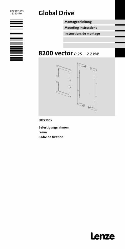
Standard devices in the power range 1.5 ... 2.2 kW
Dimensions
8200vecxxx
1 Frame
2 Screw M4x10
3 Seal
4 Hexagon nut M4
5 Rear panel of the control cabinet
Dimensions [mm]
8200 vector a b b2 c1 c2 d1 d2 d3 e 1) f 1) g
E82DV152K2C
79.4 244.5
240 4.2 71 5 80 74.5 140 100 4.5E82DV222K2C
E82DV152K4C
E82DV222k4C
1) If the function module is attached: observe mounting clearance and cable bending radius. Theterminals of function modules in PT design protrude above the housing by 14 mm.
Cutout in the control cabinet
Dimensions [mm]
8200 vector a1 b1 Frame
E82DV152K2C
61 221 E82ZJ00xE82DV222K2C
E82DV152K4C
E82DV222k4C
Mechanical installationStandard devices in the power range 1.5 ... 2.2 kW
EDK82ZJ003 DE/EN/FR 1.0 11 �
−H2−M_INST_TS_Mo_BL_751
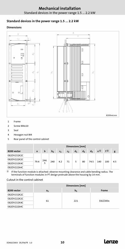
Mounting
1.
1.
2.
3.
3.
4.
5.
E82DV_002
1. Slide on frame.
2. Insert seal.
3. Slide earthing clamps on the frame with the correct sides:– The contact springs have to point towards the rear panel of the control cabinet.– The cutouts of the seal specify the positions.
4. Insert 8200 vector into cutout.
5. Tighten by means of 8 screws M4x10.– Tightening torque: 1.7 Nm (15 lb−in)

Avant−propos et généralités
EDK82ZJ003 DE/EN/FR 1.0 12 �
DUMMY_NUM_Reset−Allg BefRahmen E82Zx_FR
0Fig. 0Tab. 01 Avant−propos et généralités
Le présent fascicule
ƒ décrit le montage avec radiateur séparé (montage avec découpe de l’armoire) etcontient des indications supplémentaires sur les encombrements,
ƒ n’est valable que– pour les convertisseurs de fréquence 8200 vector E82DVxxxKxC pour la plage de
puissance 0.25 ... 2.2 kW,– conjointement avec les instructions de montage EDK82EV222.
Description
Les composants de montage permettent une fixation du variateur en cas de séparationthermique.
Dans ce cas, le radiateur se trouve à l’extérieur de l’armoire électrique.
Equipement livré
1 cadre de fixation en deux parties
1 joint
2 contacts de mise à la terre
Installation mécaniqueAppareils de base pour la plage de puissance 0.25 ... 0.75 kW
EDK82ZJ003 DE/EN/FR 1.0 13 �
H1_MechINS−M_INST_TS_Mo_BL_751
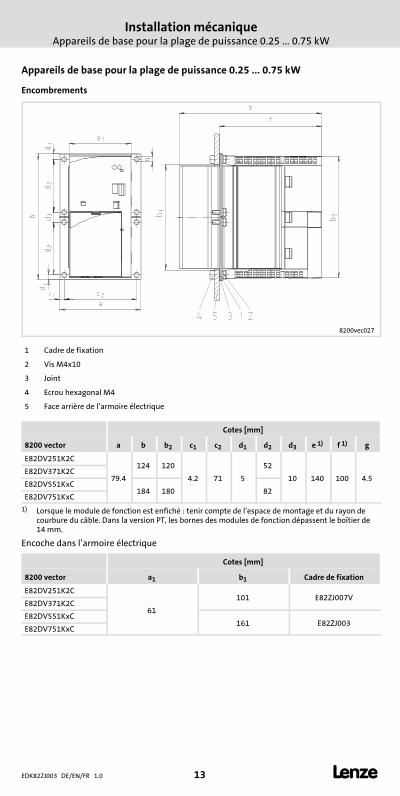
2 Installation mécanique
Appareils de base pour la plage de puissance 0.25 ... 0.75 kW
Encombrements
8200vec027
1 Cadre de fixation
2 Vis M4x10
3 Joint
4 Ecrou hexagonal M4
5 Face arrière de l’armoire électrique
Cotes [mm]
8200 vector a b b2 c1 c2 d1 d2 d3 e 1) f 1) g
E82DV251K2C
79.4
124 120
4.2 71 5
52
10 140 100 4.5E82DV371K2C
E82DV551KxC184 180 82
E82DV751KxC
1) Lorsque le module de fonction est enfiché : tenir compte de l’espace de montage et du rayon decourbure du câble. Dans la version PT, les bornes des modules de fonction dépassent le boîtier de14 mm.
Encoche dans l’armoire électrique
Cotes [mm]
8200 vector a1 b1 Cadre de fixation
E82DV251K2C
61
101 E82ZJ007VE82DV371K2C
E82DV551KxC161 E82ZJ003
E82DV751KxC

Installation mécaniqueAppareils de base pour la plage de puissance 0.25 ... 0.75 kW
EDK82ZJ003 DE/EN/FR 1.0 14 �
H1_MechINS−M_INST_TS_Mo_BL_751
Montage
3.
3.2.
1.
1.
4.
5.
E82DV_001
1. Faire glisser le cadre de fixation.
2. Poser le joint.
3. Placer correctement les brides de mise à la terre sur le cadre de fixation :– Les ressorts de contact doivent être orientés vers la face arrière de l’armoire
électrique.– Les encoches du joint indiquent les positions correctes.
4. Insérer le 8200 vector dans l’encoche.
5. Fixer l’ensemble à l’aide de 8 vis M4x10.– Couple de serrage : 1.7 Nm (15 lb−in)
Installation mécaniqueAppareils de base pour la plage de puissance 1.5 ... 2.2 kW
EDK82ZJ003 DE/EN/FR 1.0 15 �
−H2−M_INST_TS_Mo_BL_751
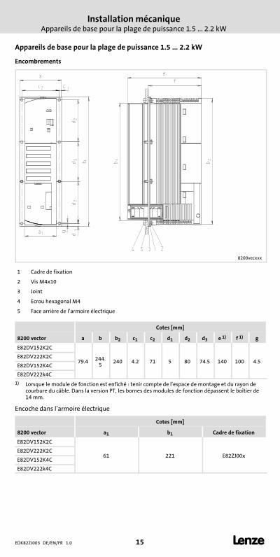
Appareils de base pour la plage de puissance 1.5 ... 2.2 kW
Encombrements
8200vecxxx
1 Cadre de fixation
2 Vis M4x10
3 Joint
4 Ecrou hexagonal M4
5 Face arrière de l’armoire électrique
Cotes [mm]
8200 vector a b b2 c1 c2 d1 d2 d3 e 1) f 1) g
E82DV152K2C
79.4 244.5
240 4.2 71 5 80 74.5 140 100 4.5E82DV222K2C
E82DV152K4C
E82DV222k4C
1) Lorsque le module de fonction est enfiché : tenir compte de l’espace de montage et du rayon decourbure du câble. Dans la version PT, les bornes des modules de fonction dépassent le boîtier de14 mm.
Encoche dans l’armoire électrique
Cotes [mm]
8200 vector a1 b1 Cadre de fixation
E82DV152K2C
61 221 E82ZJ00xE82DV222K2C
E82DV152K4C
E82DV222k4C
Installation mécaniqueAppareils de base pour la plage de puissance 1.5 ... 2.2 kW
EDK82ZJ003 DE/EN/FR 1.0 16 �
−H2−M_INST_TS_Mo_BL_751
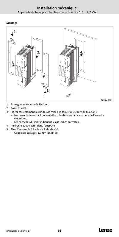
Montage
1.
1.
2.
3.
3.
4.
5.
E82DV_002
1. Faire glisser le cadre de fixation.
2. Poser le joint.
3. Placer correctement les brides de mise à la terre sur le cadre de fixation :– Les ressorts de contact doivent être orientés vers la face arrière de l’armoire
électrique.– Les encoches du joint indiquent les positions correctes.
4. Insérer le 8200 vector dans l’encoche.
5. Fixer l’ensemble à l’aide de 8 vis M4x10.– Couple de serrage : 1.7 Nm (15 lb−in)

Installation mécaniqueAppareils de base pour la plage de puissance 1.5 ... 2.2 kW
EDK82ZJ003 DE/EN/FR 1.0 17 �
−H2−M_INST_TS_Mo_BL_751

backside
�© 11/2009
� Lenze Drives GmbHPostfach 10 13 52D−31763 HamelnGermany
Service Lenze Service GmbHBreslauer Straße 3D−32699 ExtertalGermany
� +49�(0)51�54�/ 82−0 � 00�80�00�/ 24�4�68�77 (24 h helpline)
� +49�(0)51�54�/ 82−28 00 � +49�(0)51�54�/ 82−11 12
� [email protected] � [email protected]
� www.Lenze.com
EDK82ZJ003 � .A9g � DE/EN/FR � 1.0 � TD29
10 9 8 7 6 5 4 3 2 1
Recommended