Embed Size (px)
DESCRIPTION
Mant. Manual 8mm Tape cartridge unit
Citation preview
510003-001
(;%�������PP�&DUWULGJH�7DSH�6XEV\VWHP
0DLQWHQDQFH�0DQXDO

Copyright
Copyright 1990 by EXABYTE Corporation. All rights reserved. This item andthe information contained herein are the property of EXABYTE Corporation.No part of this document may be reproduced, transmitted, transcribed, stored ina retrieval system, or translated into any language or computer language in anyform or by any means, electronic, mechanical, magnetic, optical, chemical,manual or otherwise, without the express written permission of EXABYTECorporation, 1745 38th Street, Boulder, Colorado 80301.
Disclaimer
EXABYTE Corporation makes no representation or warranties with respect tothe contents of this document and specifically disclaims any implied warrantiesof merchantability or fitness for any particular purpose. Further, EXABYTECorporation reserves the right to revise this publication and to make changes init from time to time without obligation of EXABYTE Corporation to notify anyperson or organization of such revision or changes.
Trademark Notices
EXABYTE and EXATAPE are trademarks of EXABYTE Corporation. Loctiteis a registered trademark of Loctite Corporation. TORX is a registered trademarkof Camcar Division of Textron Inc.
ii 510003-001
Revision History
Revision No. Date Revision Information
000 January 1989 Preliminary version.
001 May 1990 Initial release.
May 1990 iii

iv 510003-001
Table of Contents
1 General Information . . . . . . . . . . . . . . . . . . . . . . . . . . . . . . . . . . 1
1.1 About This Manual . . . . . . . . . . . . . . . . . . . . . . . . . . . . . . . . 11.1.1 Intended Audience . . . . . . . . . . . . . . . . . . . . . . . . . . . . . 11.1.2 Related Publications . . . . . . . . . . . . . . . . . . . . . . . . . . . . 11.1.3 Revisions . . . . . . . . . . . . . . . . . . . . . . . . . . . . . . . . . . 2
1.2 Static Protection Requirements . . . . . . . . . . . . . . . . . . . . . . . . . . 21.3 Test and Repair Environment . . . . . . . . . . . . . . . . . . . . . . . . . . . 31.4 Required Test Tapes . . . . . . . . . . . . . . . . . . . . . . . . . . . . . . . . 41.5 Required Tools and Test Equipment . . . . . . . . . . . . . . . . . . . . . . . 5
1.5.1 Tools . . . . . . . . . . . . . . . . . . . . . . . . . . . . . . . . . . . . 51.5.2 Test Equipment . . . . . . . . . . . . . . . . . . . . . . . . . . . . . . 51.5.3 Software . . . . . . . . . . . . . . . . . . . . . . . . . . . . . . . . . . 61.5.4 Supplies . . . . . . . . . . . . . . . . . . . . . . . . . . . . . . . . . . 6
1.6 EXB-8200 Unit Test . . . . . . . . . . . . . . . . . . . . . . . . . . . . . . . 61.6.1 Preparation . . . . . . . . . . . . . . . . . . . . . . . . . . . . . . . . . 61.6.2 Testing the EXB-8200 . . . . . . . . . . . . . . . . . . . . . . . . . . . 6
2 Adding and Removing an EXB-8200 in the Test and Repair Environment . . . . . 9
2.1 Adding an EXB-8200 to the Test Environment . . . . . . . . . . . . . . . . . . 92.2 Removing an EXB-8200 from the Test Environment . . . . . . . . . . . . . . . 13
3 R-Pack Removal and Replacement . . . . . . . . . . . . . . . . . . . . . . . . . . 15
3.1 R-Pack Configurations . . . . . . . . . . . . . . . . . . . . . . . . . . . . . . 153.2 DIP Mounted R-Pack Removal . . . . . . . . . . . . . . . . . . . . . . . . . . 153.3 DIP Mounted R-Pack Installation . . . . . . . . . . . . . . . . . . . . . . . . . 153.4 SIP Mounted R-Pack Removal . . . . . . . . . . . . . . . . . . . . . . . . . . 173.5 SIP Mounted R-Pack Installation . . . . . . . . . . . . . . . . . . . . . . . . . 17
4 Top Cover Removal and Replacement . . . . . . . . . . . . . . . . . . . . . . . . . 19
4.1 Top Cover Removal . . . . . . . . . . . . . . . . . . . . . . . . . . . . . . . . 194.2 Top Cover Replacement . . . . . . . . . . . . . . . . . . . . . . . . . . . . . . 21
5 SV Card Cover Removal and Replacement . . . . . . . . . . . . . . . . . . . . . . 23
5.1 SV Card Cover Removal . . . . . . . . . . . . . . . . . . . . . . . . . . . . . 235.2 SV Card Cover Replacement . . . . . . . . . . . . . . . . . . . . . . . . . . . 23
May 1990 v
6 Card Retainer Removal and Replacement . . . . . . . . . . . . . . . . . . . . . . 25
6.1 Preparation . . . . . . . . . . . . . . . . . . . . . . . . . . . . . . . . . . . . 256.2 Remove Card Retainers . . . . . . . . . . . . . . . . . . . . . . . . . . . . . . 256.3 Replace Card Retainers . . . . . . . . . . . . . . . . . . . . . . . . . . . . . . 256.4 Reassemble the EXB-8200 . . . . . . . . . . . . . . . . . . . . . . . . . . . . 25
7 Deck Hanger Removal and Replacement . . . . . . . . . . . . . . . . . . . . . . . 27
7.1 Preparation . . . . . . . . . . . . . . . . . . . . . . . . . . . . . . . . . . . . 277.2 Deck Hanger Removal . . . . . . . . . . . . . . . . . . . . . . . . . . . . . . 277.3 Deck Hanger Replacement . . . . . . . . . . . . . . . . . . . . . . . . . . . . 277.4 Reassemble the EXB-8200 . . . . . . . . . . . . . . . . . . . . . . . . . . . . 28
8 Edge Connector Mounted Card Removal and Replacement . . . . . . . . . . . . . 29
8.1 MX Card Compatibility . . . . . . . . . . . . . . . . . . . . . . . . . . . . . . 298.2 Preparation . . . . . . . . . . . . . . . . . . . . . . . . . . . . . . . . . . . . 298.3 Proper Handling of Printed Circuit Cards . . . . . . . . . . . . . . . . . . . . . 318.4 Edge Connector Mounted Card Removal . . . . . . . . . . . . . . . . . . . . . 318.5 RW Card Connections . . . . . . . . . . . . . . . . . . . . . . . . . . . . . . 338.6 Replace Edge Connector Mounted Cards . . . . . . . . . . . . . . . . . . . . . 338.7 Reassemble the EXB-8200 . . . . . . . . . . . . . . . . . . . . . . . . . . . . 33
9 SV Card Removal and Replacement . . . . . . . . . . . . . . . . . . . . . . . . . . 35
9.1 Preparation . . . . . . . . . . . . . . . . . . . . . . . . . . . . . . . . . . . . 359.2 Proper Handling of Printed Circuit Cards . . . . . . . . . . . . . . . . . . . . . 359.3 Remove Mounting Screws . . . . . . . . . . . . . . . . . . . . . . . . . . . . 359.4 Disconnect SV Card Connectors . . . . . . . . . . . . . . . . . . . . . . . . . 379.5 Reconnect the SV Card Connections . . . . . . . . . . . . . . . . . . . . . . . 409.6 Reattach the SV Card to the Main Housing . . . . . . . . . . . . . . . . . . . . 409.7 Reassemble the EXB-8200 . . . . . . . . . . . . . . . . . . . . . . . . . . . . 41
10 MX EPROM Removal and Replacement . . . . . . . . . . . . . . . . . . . . . . 43
10.1 Preparation . . . . . . . . . . . . . . . . . . . . . . . . . . . . . . . . . . . . 4310.2 Identification Information . . . . . . . . . . . . . . . . . . . . . . . . . . . . 4310.3 EPROM Removal . . . . . . . . . . . . . . . . . . . . . . . . . . . . . . . . 4510.4 EPROM Installation . . . . . . . . . . . . . . . . . . . . . . . . . . . . . . . 4710.5 Reassemble the EXB-8200 . . . . . . . . . . . . . . . . . . . . . . . . . . . 49
11 SV Card EPROM Removal and Replacement . . . . . . . . . . . . . . . . . . . . 51
11.1 Proper Handling of Printed Circuit Cards . . . . . . . . . . . . . . . . . . . . 5111.2 Preparation for SV Card 721103-Bxx . . . . . . . . . . . . . . . . . . . . . . 51
vi 510003-001
11.3 EPROM Removal for SV Card 721103-Bxx . . . . . . . . . . . . . . . . . . 5111.4 Preparation for SV Card 721102-Bxx . . . . . . . . . . . . . . . . . . . . . . 5311.5 EPROM Removal for SV Card 721102-Bxx . . . . . . . . . . . . . . . . . . 5311.6 EPROM Installation . . . . . . . . . . . . . . . . . . . . . . . . . . . . . . . 5311.7 Reassemble the EXB-8200 . . . . . . . . . . . . . . . . . . . . . . . . . . . 55
12 Faceplate Removal and Replacement . . . . . . . . . . . . . . . . . . . . . . . . . 57
12.1 Faceplate Removal . . . . . . . . . . . . . . . . . . . . . . . . . . . . . . . . 5712.2 Faceplate Replacement . . . . . . . . . . . . . . . . . . . . . . . . . . . . . . 59
13 Door Removal and Replacement . . . . . . . . . . . . . . . . . . . . . . . . . . . 61
13.1 Preparation . . . . . . . . . . . . . . . . . . . . . . . . . . . . . . . . . . . . 6113.2 Door Removal . . . . . . . . . . . . . . . . . . . . . . . . . . . . . . . . . . 6113.3 Door Replacement . . . . . . . . . . . . . . . . . . . . . . . . . . . . . . . . 63
14 Deck Assembly Removal and Replacement . . . . . . . . . . . . . . . . . . . . . 65
14.1 Preparation . . . . . . . . . . . . . . . . . . . . . . . . . . . . . . . . . . . . 6514.2 Deck Removal . . . . . . . . . . . . . . . . . . . . . . . . . . . . . . . . . . 6514.3 Deck Replacement . . . . . . . . . . . . . . . . . . . . . . . . . . . . . . . . 6714.4 Reassemble the EXB-8200 . . . . . . . . . . . . . . . . . . . . . . . . . . . 67
15 Main Housing Removal and Replacement . . . . . . . . . . . . . . . . . . . . . . 69
15.1 Preparation . . . . . . . . . . . . . . . . . . . . . . . . . . . . . . . . . . . . 6915.2 Main Housing Removal . . . . . . . . . . . . . . . . . . . . . . . . . . . . . 6915.3 Main Housing Replacement . . . . . . . . . . . . . . . . . . . . . . . . . . . 7015.4 Reassemble the EXB-8200 . . . . . . . . . . . . . . . . . . . . . . . . . . . 70
16 Cleaning Procedure . . . . . . . . . . . . . . . . . . . . . . . . . . . . . . . . . . 71
16.1 Accepted Procedures and Products . . . . . . . . . . . . . . . . . . . . . . . 7116.2 Cleaning Intervals . . . . . . . . . . . . . . . . . . . . . . . . . . . . . . . . 7116.3 Minimum Firmware Level Required . . . . . . . . . . . . . . . . . . . . . . 7116.4 Cleaning Action Performed by Cartridge . . . . . . . . . . . . . . . . . . . . 7216.5 Usage and Reusage . . . . . . . . . . . . . . . . . . . . . . . . . . . . . . . 7216.6 Cleaning Instructions . . . . . . . . . . . . . . . . . . . . . . . . . . . . . . 72
17 Tape Removal Procedure . . . . . . . . . . . . . . . . . . . . . . . . . . . . . . . 73
17.1 Preparation . . . . . . . . . . . . . . . . . . . . . . . . . . . . . . . . . . . . 7317.2 Definitions . . . . . . . . . . . . . . . . . . . . . . . . . . . . . . . . . . . . 7317.3 Required Tools . . . . . . . . . . . . . . . . . . . . . . . . . . . . . . . . . . 7517.4 Disconnect the EXB-8200 . . . . . . . . . . . . . . . . . . . . . . . . . . . . 75
May 1990 vii
17.5 Preparation of the EXB-8200 . . . . . . . . . . . . . . . . . . . . . . . . . . 7517.6 Cartridge Preparation . . . . . . . . . . . . . . . . . . . . . . . . . . . . . . 7517.7 Erase Head Bracket Removal . . . . . . . . . . . . . . . . . . . . . . . . . . 7717.8 Tape Guide Removal . . . . . . . . . . . . . . . . . . . . . . . . . . . . . . 7717.9 Tape Removal . . . . . . . . . . . . . . . . . . . . . . . . . . . . . . . . . . 7917.10 Remove Faceplate and Open Door . . . . . . . . . . . . . . . . . . . . . . . 8117.11 Wind Loose Tape and Eject Data Cartridge . . . . . . . . . . . . . . . . . . 8117.12 Reassemble the EXB-8200 . . . . . . . . . . . . . . . . . . . . . . . . . . . 82
18 Head Sync Adjustment Procedure . . . . . . . . . . . . . . . . . . . . . . . . . . 83
18.1 Requirements . . . . . . . . . . . . . . . . . . . . . . . . . . . . . . . . . . 8318.1.1 Tools . . . . . . . . . . . . . . . . . . . . . . . . . . . . . . . . . . . 8318.1.2 Test Equipment . . . . . . . . . . . . . . . . . . . . . . . . . . . . . . 8318.1.3 Software and User’s Manuals . . . . . . . . . . . . . . . . . . . . . . 85
18.2 Preparation . . . . . . . . . . . . . . . . . . . . . . . . . . . . . . . . . . . . 8518.3 Scope Settings . . . . . . . . . . . . . . . . . . . . . . . . . . . . . . . . . . 8718.4 Check the Head Sync Timing. . . . . . . . . . . . . . . . . . . . . . . . . . 8718.5 Adjust the Head Sync Timing . . . . . . . . . . . . . . . . . . . . . . . . . . 9118.6 Verify the Adjustment . . . . . . . . . . . . . . . . . . . . . . . . . . . . . . 9218.7 Reassemble the EXB-8200 . . . . . . . . . . . . . . . . . . . . . . . . . . . 92
viii 510003-001
Figures
Figure 2-1 Connector and Switch Locations for the DB Card . . . . . . . . . . . . . . . 8
Figure 2-2 Location of DIP Switches and Remote Connector on DS Card . . . . . . . . 8
Figure 2-3 SCSI ID DIP Switch Settings for the DB and DS Cards . . . . . . . . . . . . 10
Figure 2-4 SCSI ID Jumper Connections for the DR Card . . . . . . . . . . . . . . . . . 10
Figure 2-5 SCSI ID Jumper Connections for the DS Card . . . . . . . . . . . . . . . . . 10
Figure 2-6 Location of the Unload Button . . . . . . . . . . . . . . . . . . . . . . . . . 12
Figure 3-1 Location of DIP R-Packs on Rear of EXB-8200 . . . . . . . . . . . . . . . . 14
Figure 3-2 Location of SIP R-Packs on Rear of EXB-8200 . . . . . . . . . . . . . . . . 16
Figure 4-1 Location of Screws in Top Cover . . . . . . . . . . . . . . . . . . . . . . . . 18
Figure 4-2 Location of Screws in Top Cover (same as Figure 4-1) . . . . . . . . . . . . 20
Figure 5-1 Location of Screws in the SV Card Cover . . . . . . . . . . . . . . . . . . . 22
Figure 6-1 Location of Card Retainers (deck hanger not shown) . . . . . . . . . . . . . 24
Figure 7-1 Location of Deck Hanger . . . . . . . . . . . . . . . . . . . . . . . . . . . . 26
Figure 8-1 Location of Edge Connector Mounted Cards . . . . . . . . . . . . . . . . . . 30
Figure 8-2 Location of RW Card Wire Harness Connections . . . . . . . . . . . . . . . 32
Figure 9-1 Location of SV Card Mounting Screws . . . . . . . . . . . . . . . . . . . . 34
Figure 9-2 Location of SV Card Connectors . . . . . . . . . . . . . . . . . . . . . . . . 36
Figure 9-3 Connector Key Sockets . . . . . . . . . . . . . . . . . . . . . . . . . . . . . 38
Figure 10-1 Location of Edge Connector Mounted Cards . . . . . . . . . . . . . . . . . 42
Figure 10-2 Location of EPROM for MX, MS, or MV Cards . . . . . . . . . . . . . . . 44
Figure 10-3 Location of EPROM for MX and MS Cards . . . . . . . . . . . . . . . . . 44
Figure 10-4 Location of EPROM for MX, MS, or MV Cards (same as Figure 10-2) . . . 46
Figure 10-5 Location of EPROM for MX and MS Cards (same as Figure 10-3) . . . . . 46
Figure 10-6 Location of Edge Connector Mounted Cards . . . . . . . . . . . . . . . . . 48
Figure 11-1 Location of SV Card EPROM for SV Card 721103-Bxx . . . . . . . . . . . 50
Figure 11-2 Location of SV Card EPROM for SV Card 721102-Bxx . . . . . . . . . . . 52
Figure 11-3 Location of SV Card EPROM for SV Card 721102-Bxx
(same as Figure 11-2) . . . . . . . . . . . . . . . . . . . . . . . . . . . . . . . . . . . . 54
Figure 12-1 Location of Door Release Lever . . . . . . . . . . . . . . . . . . . . . . . 56
Figure 12-2 Location of Faceplate Mounting Screws . . . . . . . . . . . . . . . . . . . 56
Figure 12-3 Location of Faceplate Mounting Screws (same as Figure 12-2) . . . . . . . 58
Figure 13-1 Location of Door Release Lever . . . . . . . . . . . . . . . . . . . . . . . 60
Figure 13-2 Door and Door Retainer Separation . . . . . . . . . . . . . . . . . . . . . . 60
May 1990 ix
Figure 13-3 Relationship among the Door, Door Retainer, and Door Bracket . . . . . . . 62
Figure 14-1 Location of Deck Mounting Screws . . . . . . . . . . . . . . . . . . . . . . 64
Figure 14-2 Location of Deck Mounting Screws (same as Figure 14-1) . . . . . . . . . . 66
Figure 15-1 Main Housing Removal . . . . . . . . . . . . . . . . . . . . . . . . . . . . 68
Figure 17-1 Data Cartridge with Door Taped Open . . . . . . . . . . . . . . . . . . . . 74
Figure 17-2 EXB-8200 with Tape Loaded . . . . . . . . . . . . . . . . . . . . . . . . . 76
Figure 17-3 EXB-8200 with Tape Loaded . . . . . . . . . . . . . . . . . . . . . . . . 78
Figure 17-4 EXB-8200 with Tape Loaded (same as Figure 17-3) . . . . . . . . . . . . . 80
Figure 18-1 Oscilloscope Connections for the Head Sync Timing Procedure. . . . . . . 84
Figure 18-2 Waveforms . . . . . . . . . . . . . . . . . . . . . . . . . . . . . . . . . . 86
Figure 18-3 Waveforms (same as Figure 18-2) . . . . . . . . . . . . . . . . . . . . . . 88
Figure 18-4 Waveforms (same as Figure 18-2) . . . . . . . . . . . . . . . . . . . . . . 90
Tables
Table 2-1 Pin Assignments on the Remote Connector . . . . . . . . . . . . . . . . . . . 11
Table 10-1 MV/MX/MS PCB Part Numbers . . . . . . . . . . . . . . . . . . . . . . . . 45
x 510003-001
1 General Information
TheEXB-8200 8mm Cartridge Tape Subsystem Maintenance Manualde-scribes how to repair or test an EXABYTE™ EXB-8200 8mm Cartridge TapeSubsystem (EXB-8200).
1.1 About This Manual
This manual contains 18 sections. Section 1 provides general information thatyou need to know before you begin testing or repairing the EXB-8200, includ-ing information about the following:
Static protection requirementsThe test and repair environmentRequired test tapesRequired tools and test equipmentRelated publicationsPerforming an EXB-8200 unit test.
Sections 2 through 18 of this manual describe how to repair, maintain, andtest the EXB-8200. Each section describes the preparation needed for eachtask and then provides step-by-step instructions for completing the task.
The instructions in each section of this manual are organized so that all fig-ures appear on a left-hand page and the associated descriptions appear on theadjacent right-hand page. If the description associated with a figure continuesbeyond a single page, the figure is repeated.
1.1.1 Intended Audience
This manual is provided to assist EXABYTE Self Maintenance Contract Cus-tomers in the repair and testing of the EXB-8200.
1.1.2 Related Publications
The following manuals and user’s guides are referred to in this manual.These manuals and guide books are necessary to understand and accomplishsome of the tasks referred to in this manual.
EXB-8200 8mm Cartridge Tape Subsystem User’s Manual, 510006
EXB-8200 8mm Cartridge Tape Subsystem Product Specification, 510005
EXB-8200 8mm Cartridge Tape Subsystem Compatibility Manual, 510002
May 1990 1
1 General Information
Monitor User’s Guide for the EXB-8200 8mm Cartridge Tape Subsystem,510009
EXPERT User’s Guide for the EXB-8200 8mm Cartridge Tape Subsystem,510010.
The following books are also useful in understanding the EXB-8200, and it isrecommended that they be kept with this manual:
EXB-8200 8mm Cartridge Tape Subsystem Theory of Operations, 510007
EXB-8200 8mm Cartridge Tape Subsystem Illustrated Parts Catalog,510000.
1.1.3 Revisions
This document may be revised in whole or in part at any time. If only a sin-gle section is revised or added, only those pages will be distributed to the reg-istered holders of this manual.
1.2 Static Protection Requirements
The test and repair environment for the EXB-8200 must be free of conditionsthat could cause electrostatic discharge (ESD). To ensure that the testing envi-ronment is as free from ESD as possible, follow these procedures when test-ing and repairing the EXB-8200:
Place a static protection mat on the work surface used for testing and re-pairing the EXB-8200. Use a 1-megohm resistor to ground the static pro-tection mat.
Ensure that the power supply connected to the EXB-8200 is properlygrounded.
Ensure that the personal computer used for EXPERT and Monitor soft-ware and for the SCSI bus is properly grounded.
Wear a static protection wrist band whenever you handle the EXB-8200or EXB-8200 cards that have been removed from their antistatic bags.Connect this wrist band to the static protection mat or to other suitableESD grounding.
Keep all cards in antistatic bags when not in use.
2 510003-001
1 General Information

1.3 Test and Repair Environment
The environment for testing or repairing the EXB-8200 consists of the follow-ing:
A work area set up with static protection as described in Section 1.2 ofthis manual.
A power supply that conforms to the requirements of theEXB-8200 8mmCartridge Tape Subsystem Product Specificationfor each EXB-8200 un-der test.
An IBM or compatible personal computer system with a color monitorand serial port.
An Adaptec SDS-1 family or SDS-3 family SCSI controller or an Ad-vanced Storage Concepts ASC-88 SCSI controller installed in the com-puter system.
A SCSI bus cable properly connected to the Adaptec or ASC-88 controllerand properly terminated.
An EXABYTE Monitor cable (727005) connected to the serial communi-cations port on the computer system.
EXABYTE Monitor software (version 9.12 or later) loaded on the com-puter system.
EXABYTE EXPERT software (version 6.30 or later) loaded on the com-puter system.
Any other equipment that may be required or specified in testing specifica-tions and procedures published by EXABYTE.
Note: There are no exceptions to the environmental requirements unless spe-cifically agreed to in writing by the customer and EXABYTE. Suchan agreement will become part of this manual as an addendum to thissection.
May 1990 3
1 General Information
1.4 Required Test Tapes
This section describes the tapes that are required to test the EXB-8200 and themethods to be followed in creating them. Label these tapes appropriately foreasy identification.
Test tapeRead Interchange test tapeWrite Interchange test tapeEXABYTE Head Sync Tapes (180223), where applicable.
Test Tape
The test tape is used for all testing with EXPERT test software. It should bean EXATAPE™ 112m tape.
Read Interchange Test Tape
The tape used for the Read Interchange test should be an EXATAPE 15mtape. This tape is written by the EXPERT Inter_chg test on a known gooddrive.
Write Interchange Test Tape
The tape used for the Write Interchange test should be an EXATAPE 15mtape. This tape is written by the EXPERT Inter_chg test on the drive beingtested. It is read by a known good drive to verify interchangeability.
EXABYTE Head Sync Tapes
At least two head sync tapes are required to adjust the head sync any time anSV card or deck is replaced.
4 510003-001
1 General Information
1.5 Required Tools and Test Equipment
This section describes the tools and test equipment required to test and repairthe EXB-8200.
1.5.1 Tools
The following tools are necessary to work on the EXB-8200:
T8 - TORX® screwdriverT10 - TORX screwdriverTorque measuring screwdriver (1.0 to 5.0 inch-pounds)TweezersEPROM chip pullerSmall straight blade screwdriver - # 0Small cross blade (Phillips) screwdriver - # 1SCSI bus cableMonitor cable (727005)EPROM chip installation toolNeedle nose pliersNonconductive tool, such as a molded potentiometer adjustment tool.
1.5.2 Test Equipment
The following test equipment is necessary to work on EXABYTE products:
Two channel oscilloscope (50 MHz with time delay capability) with ahood.
Regulated +5/+12 VDC power supply.
IBM or compatible personal computer system with a color monitor and se-rial port.
Adaptec SDS-1 family or SDS-3 family SCSI controller or an AdvancedStorage Concepts ASC-88 SCSI controller installed in the computer sys-tem.
May 1990 5
1 General Information
1.5.3 Software
The following software is recommended to test the EXB-8200:
EXPERT Version 6.30 or later.
Runtime For Adaptec SDS-1 family SCSI controllers. TheRuntime executable file is provided by Adaptecwhen the controller is purchased. Adaptec SDS-3family and ASC-88 SCSI controllers do not needany special software.
Monitor Version 9.12 or later.
1.5.4 Supplies
The following supplies are necessary for testing, repairing, and maintainingthe EXB-8200:
Test tapes (see Section 1.4 for descriptions)
EXABYTE 8mm Tape Subsystem Cleaning Cartridge (727113)
Threebond screwlocking agent (item number 1401B)
Loctite® X-NMS Cleanup Solvent (item number 76820).
1.6 EXB-8200 Unit Test
This section describes how to test an EXB-8200 to determine functionalityand to evaluate its performance when troubleshooting.
1.6.1 Preparation
Read Sections 1 and 2 of this manual and theEXPERT User’s Guide for theEXB-8200 8mm Cartridge Tape Subsystembefore testing any EXB-8200.
1.6.2 Testing the EXB-8200
All the tests listed in theEXPERT User’s Guideare useful for evaluating per-formance of the EXB-8200. Each test was written to evaluate performance ofthe EXB-8200 while doing specific types of operations. See theEXPERTUser’s Guidefor details.
Each EXB-8200 under test should use a known good power supply to verifyoperation and to eliminate any outside influences on the test. Verify that allpower to the test area is clean and free of any type of feedback or inductive
6 510003-001
1 General Information
spikes. Power problems will typically cause a high percentage of ECC or ex-treme difficulty getting known good EXB-8200s to pass the tests consistently.
Test tapes should be closely monitored to ensure that any failures reported byEXPERT are EXB-8200 related rather than tape related. In the event of a me-dia error, rerun the test with a known good tape to verify the failure.
To ensure accuracy and consistency when testing a string of EXB-8200s, startall EXB-8200s at the same time and run them without interruption to comple-tion. Doing this reduces the likelihood of operator error and computer soft-ware hangs. Many hours of testing can be negated by a simple operator error.
May 1990 7
1 General Information
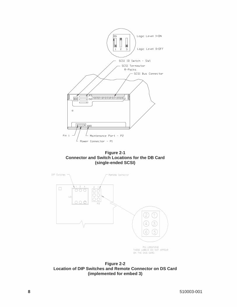
Figure 2-1Connector and Switch Locations for the DB Card
(single-ended SCSI)
Figure 2-2Location of DIP Switches and Remote Connector on DS Card
(implemented for embed 3)
8 510003-001

2 Adding and Removing an EXB-8200 in the Test and Re-pair Environment
This section describes how to add an EXB-8200 to or remove it from the testand repair environment described in Section 1.3. Follow this procedure to pre-vent possible problems for the other devices being tested on the SCSI bus.
2.1 Adding an EXB-8200 to the Test Environment
When there is an available address on the SCSI bus and tests are being per-formed on other EXB-8200s attached to the bus, follow these steps to add anew EXB-8200 to the bus.
IMPORTANT
These steps assume that each EXB-8200 has its own power supply. Ifmore than one EXB-8200 share the same power supply, adding anEXB-8200 to the power supply’s load may momentarily drop the5 volt power level below 4.7 volts, which will reset the SCSI bus. Us-ing individual, switched power supplies for each EXB-8200 under testhelps eliminate possible interference.
1. Stop SCSI bus activity by pressing the function key corresponding to theSCSI ID for the available position in the EXPERT display. Refer to theEXPERT User’s Guidefor instructions.
2. If you are using a single-ended SCSI configuration, remove the resistorterminator packs (R-packs) from the EXB-8200. See Section 3.
3. If you have a DB or DS card, locate the SCSI ID DIP switches on theback of the EXB-8200 as shown in Figure 2-1. Depending on the ver-sion of the DB or DS card you have, the back of the EXB-8200 may lookslightly different; however, the SCSI ID switches are in the same loca-tion. Note that some DS cards include both DIP switches and a remoteconnector as shown in Figure 2-2. If you have one of these cards, youcan use the DIP switches, a remote switch, or jumpers to set the SCSI ID.
If you have a DR card, locate the remote connector in the upper left-handcorner on the back of the EXB-8200. You can use either a remote switchor jumpers (shunts) to set the SCSI ID.
May 1990 9
2 Adding and Removing an EXB-8200 in the Test and Repair Environment
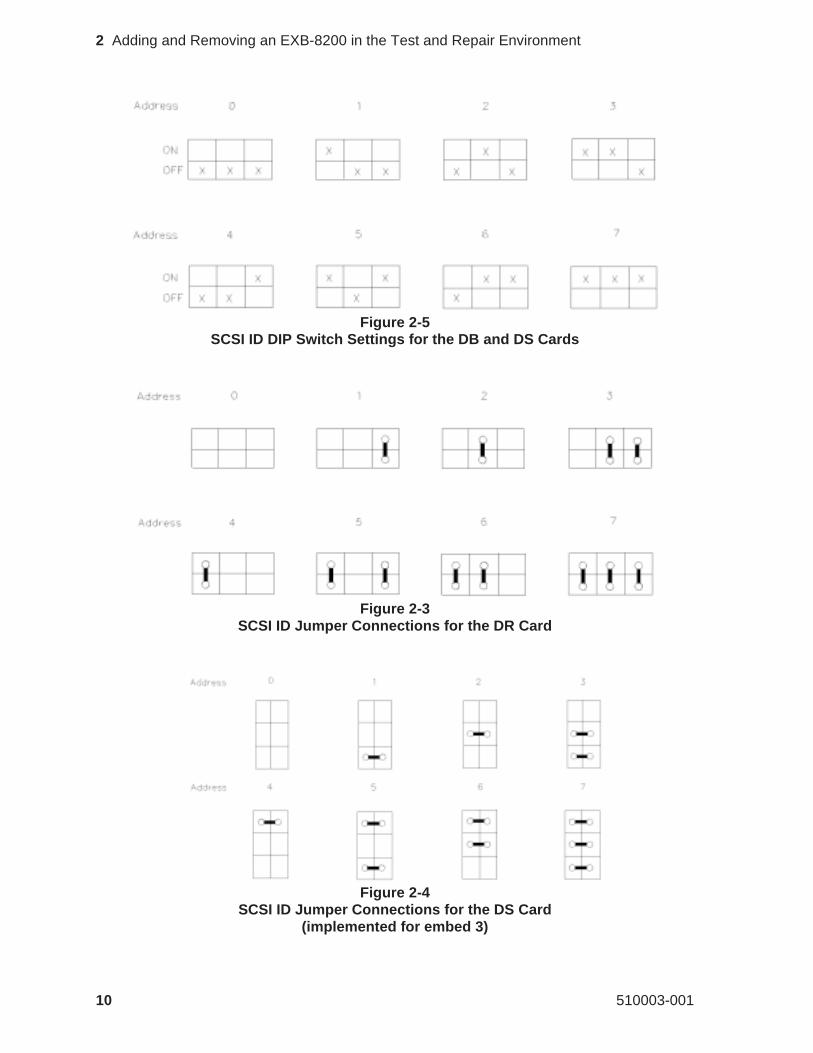
Figure 2-5SCSI ID DIP Switch Settings for the DB and DS Cards
Figure 2-3SCSI ID Jumper Connections for the DR Card
Figure 2-4SCSI ID Jumper Connections for the DS Card
(implemented for embed 3)
10 510003-001
2 Adding and Removing an EXB-8200 in the Test and Repair Environment
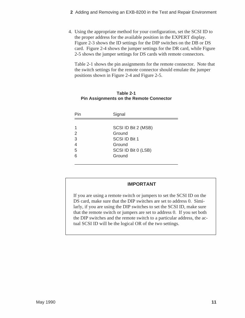
4. Using the appropriate method for your configuration, set the SCSI ID tothe proper address for the available position in the EXPERT display.Figure 2-3 shows the ID settings for the DIP switches on the DB or DScard. Figure 2-4 shows the jumper settings for the DR card, while Figure2-5 shows the jumper settings for DS cards with remote connectors.
Table 2-1 shows the pin assignments for the remote connector. Note thatthe switch settings for the remote connector should emulate the jumperpositions shown in Figure 2-4 and Figure 2-5.
Pin Signal
1 SCSI ID Bit 2 (MSB)2 Ground3 SCSI ID Bit 14 Ground5 SCSI ID Bit 0 (LSB)6 Ground
IMPORTANT
If you are using a remote switch or jumpers to set the SCSI ID on theDS card, make sure that the DIP switches are set to address 0. Simi-larly, if you are using the DIP switches to set the SCSI ID, make surethat the remote switch or jumpers are set to address 0. If you set boththe DIP switches and the remote switch to a particular address, the ac-tual SCSI ID will be the logical OR of the two settings.
Table 2-1Pin Assignments on the Remote Connector
May 1990 11
2 Adding and Removing an EXB-8200 in the Test and Repair Environment
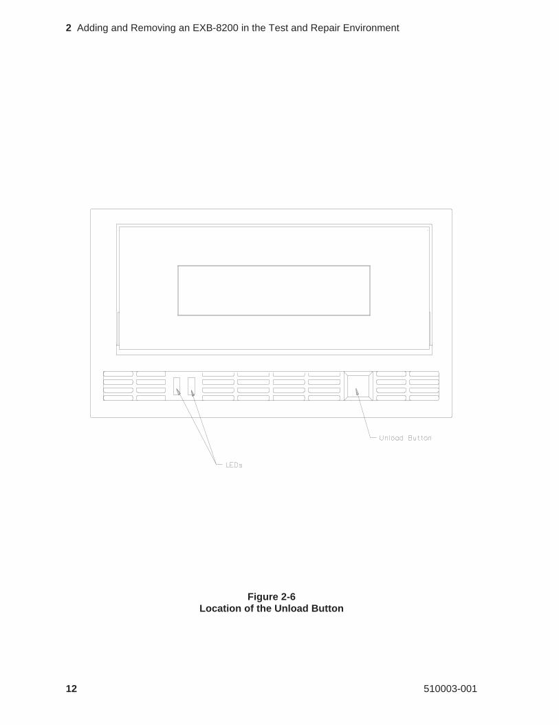
Figure 2-6Location of the Unload Button
12 510003-001
2 Adding and Removing an EXB-8200 in the Test and Repair Environment

5. Ensure that the power is interrupted (off) so that the power cable can beconnected to the EXB-8200 being tested.
6. Connect the EXB-8200 to the power supply.
7. Turn on the power supply.
Note: Do not apply power to an EXB-8200 with the SCSI bus connected, ora SCSI bus reset or error condition may result.
8. Connect the EXB-8200 to the SCSI bus cable.
9. After the power-on self-test is complete, press the unload button (shownin Figure 2-6) and insert a cartridge into the EXB-8200.
10. Activate the desired test for the new EXB-8200 added to the SCSI bus.Refer to theEXPERT User’s Guide.
2.2 Removing an EXB-8200 from the Test Environment
When the tests being performed on an EXB-8200 attached to the bus havebeen completed, follow these steps to remove the EXB-8200 from the bus:
1. Stop SCSI bus activity by selecting the desired EXB-8200.
2. Press the unload button, shown in Figure 2-6, and wait for the EXB-8200to rewind the tape and unload the cartridge.
3. Disconnect the EXB-8200 from the SCSI bus cable.
4. Turn off the power supply.
Note: Do not disconnect power to an EXB-8200 with the SCSI bus con-nected, or a SCSI bus reset or error condition may result.
5. Disconnect the EXB-8200 from the power supply.
6. If you are using a single-ended SCSI configuration, reinsert the resistorterminator packs (R-packs) into the EXB-8200. See Section 3.
May 1990 13
2 Adding and Removing an EXB-8200 in the Test and Repair Environment
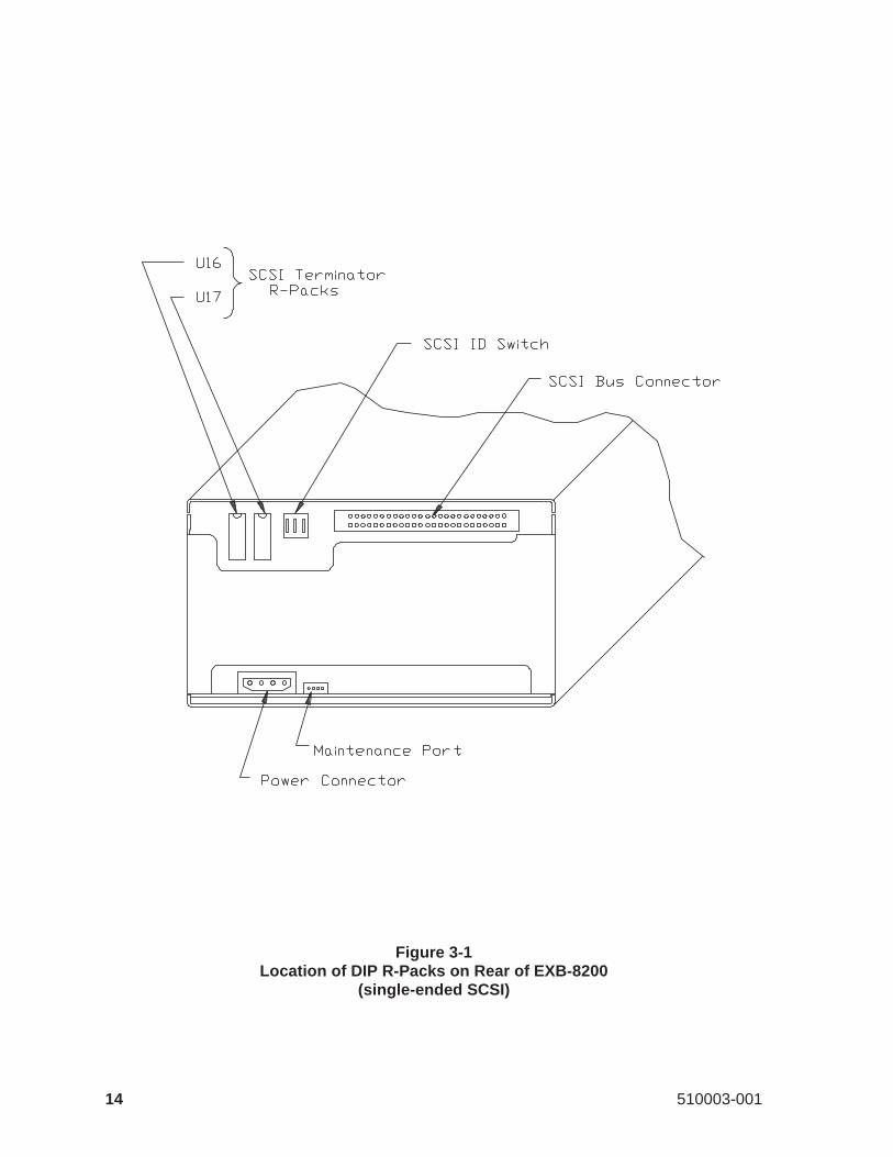
Figure 3-1Location of DIP R-Packs on Rear of EXB-8200
(single-ended SCSI)
14 510003-001
3 R-Pack Removal and Replacement
This section describes how to remove or replace the resistor terminators (R-packs).
3.1 R-Pack Configurations
As shown in Figures 3-1 and 3-2, there are two different R-pack configura-tions for the single-ended SCSI version of the EXB-8200. One configurationuses two dual in-line package (DIP) socket-mounted R-packs, and the otheruses three single in-line package (SIP) socket-mounted R-packs. The differen-tial version of the EXB-8200 does not use internal R-packs.
3.2 DIP Mounted R-Pack Removal
Figure 3-1 shows the locations of the two DIP mounted R-packs on the DBcard. The R-packs can be removed with an appropriate chip removal tool de-signed for this size chip.
3.3 DIP Mounted R-Pack Installation
The R-packs can be installed by hand or with an appropriate chip installationtool designed for this size chip.
If you are installing the R-packs by hand, follow these steps:
1. Orient the R-pack with the notch toward the top edge of the DB card.This corresponds to the notch in the socket on the DB card.
2. Carefully position the R-pack on the socket. Check to ensure that eachpin on the R-pack is aligned with a hole in the socket.
3. Press the R-pack into the socket. Be careful to provide even pressure onthe top of the R-pack so that all pins are inserted at the same time. Un-even pressure can result in the R-pack being only partially inserted or inbent pins on the R-pack.
4. Visually inspect the R-pack to ensure that all of the pins have been cor-rectly inserted in the socket. If the R-pack is not fully seated in thesocket, apply additional pressure to bottom out all pins on the R-packinto the socket.
May 1990 15
3 R-Pack Removal and Replacement
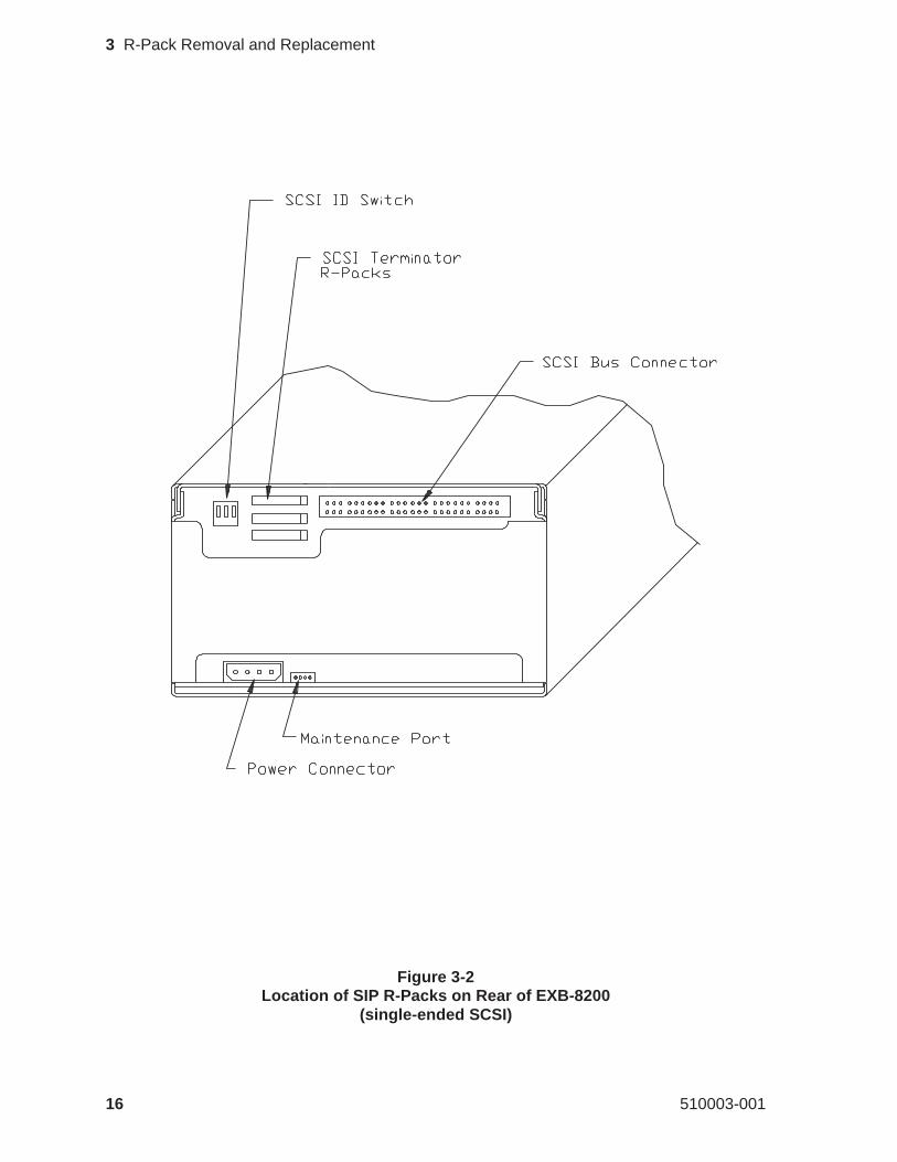
Figure 3-2Location of SIP R-Packs on Rear of EXB-8200
(single-ended SCSI)
16 510003-001
3 R-Pack Removal and Replacement
5. If any of the pins are bent, remove the R-pack. Then, straighten the pinsand reinsert the R-pack. Follow the previous steps to remove, insert, andinspect the R-pack.
Note: Do not use the R-pack if any of the pins are broken.
3.4 SIP Mounted R-Pack Removal
Figure 3-2 shows the locations of the three SIP mounted R-packs on the DBcard. To remove a SIP mounted R-pack, follow these steps:
1. Grasp the SIP in the center with a pair of needle nose pliers.
2. Pull the SIP straight out. Be careful not to squeeze the pliers too tightlyor you may break the SIP.
3.5 SIP Mounted R-Pack Installation
To install a SIP mounted R-pack, follow these steps:
1. Orient the R-pack with pin 1 toward the SCSI connector on the DB card.Pin 1 on the R-pack is identified by the wide line over the pin.
2. Carefully position the R-pack on the socket. Check to ensure that eachpin on the R-pack is aligned with a hole in the socket.
3. Press the R-pack into the socket. Be careful to provide even pressure onthe top of the R-pack so that all pins are inserted at the same time. Un-even pressure can result in the R-pack being only partially inserted or inbent pins on the R-pack.
4. Visually inspect the R-pack to ensure that all of the pins have been cor-rectly inserted. If the R-pack is not fully seated in the socket, apply addi-tional pressure to bottom out all pins on the R-pack into the socket.
5. If any of the pins are bent, remove the R-pack. Then, straighten the pinsand reinsert the R-pack. Follow the previous steps to remove, insert, andinspect the R-pack.
Note: Do not use the R-pack if any of the pins are broken.
May 1990 17
3 R-Pack Removal and Replacement
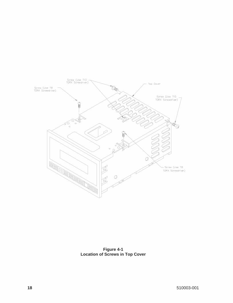
Figure 4-1Location of Screws in Top Cover
18 510003-001
4 Top Cover Removal and Replacement
This section describes how to remove and replace the top cover.
4.1 Top Cover Removal
To remove the top cover, follow these steps:
1. Remove the five screws that hold the top cover of the EXB-8200 inplace. Figure 4-1 shows the locations of these screws. Three of thescrews are located on the top of the cover, and the other two screws arelocated on each side of the cover at the rear of the EXB-8200. The twoscrews located on the top of the EXB-8200 near the edges require the useof a T8 TORX screwdriver, and the remaining three screws use a T10TORX screwdriver.
2. Gently lift the cover at the rear of the EXB-8200 so that the tabs locatedat the rear and on each side of the top cover are clear of the main housing.
3. Move the cover toward the rear of the EXB-8200 to disengage the tabson the front of the top cover from the faceplate and set the cover aside.
May 1990 19
4 Top Cover Removal and Replacement
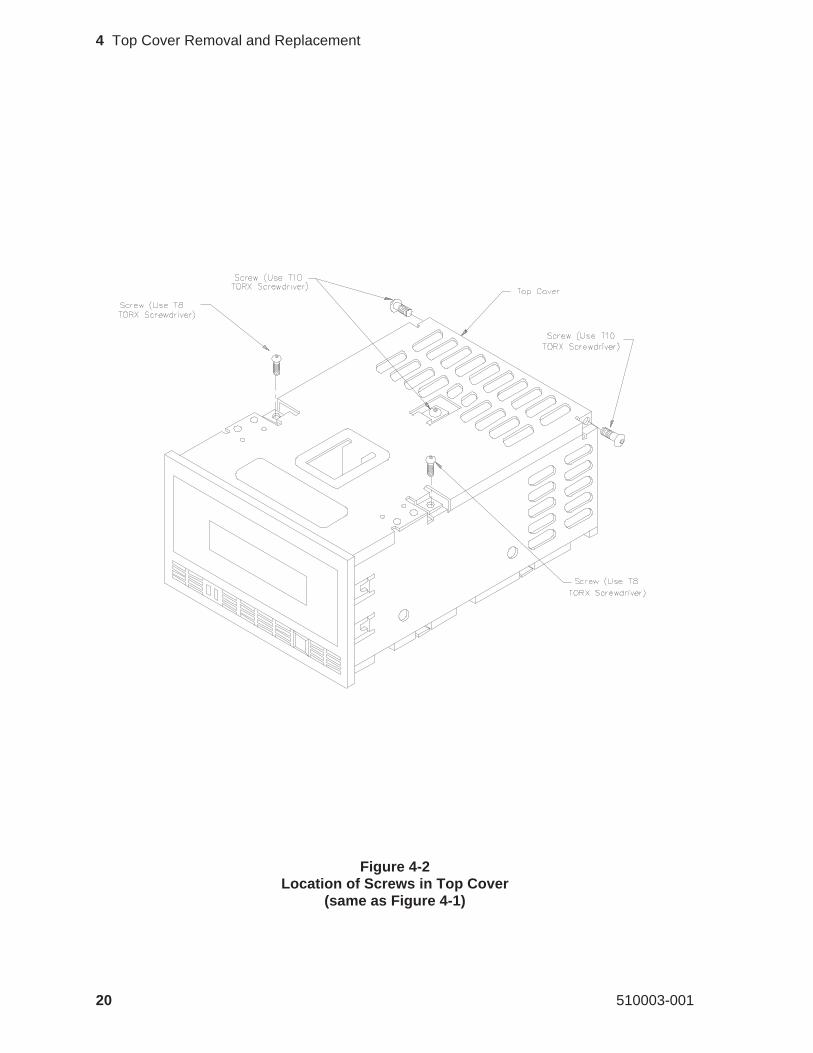
Figure 4-2Location of Screws in Top Cover
(same as Figure 4-1)
20 510003-001
4 Top Cover Removal and Replacement
4.2 Top Cover Replacement
To replace the top cover, follow these steps:
1. Position the cover with the flat tabs toward the front of the EXB-8200and the two downward bent tabs toward the rear of the EXB-8200. Therear of the cover should be held up slightly.
2. Slide the cover toward the front of the EXB-8200 so that the flat tabs areinserted into the corresponding slots on the faceplate.
3. Lower the rear of the cover so that the tabs line up with the screw holesin the card retainers. You may need to apply slight pressure to seat thetop cover properly.
4. Secure the rear of the cover through the card retainers and through the ap-proximate center of the top cover to the deck hanger using the threelarger screws (T10) (refer to Figure 4-2 for the locations of thesescrews). Tighten to 5.0 inch-pounds of torque.
5. Secure the top of the cover at the left and right edges using the twosmaller screws (T8) (refer to Figure 4-2 for the locations of thesescrews). Tighten to 3.4 inch-pounds of torque.
CAUTION
Do not overtighten the screws.Overtightening these screws canstrip the holes in the main housing, the card retainers, or the deckhanger. If any of the screw holes in the main housing becomestripped, the main housing should be replaced.
May 1990 21
4 Top Cover Removal and Replacement
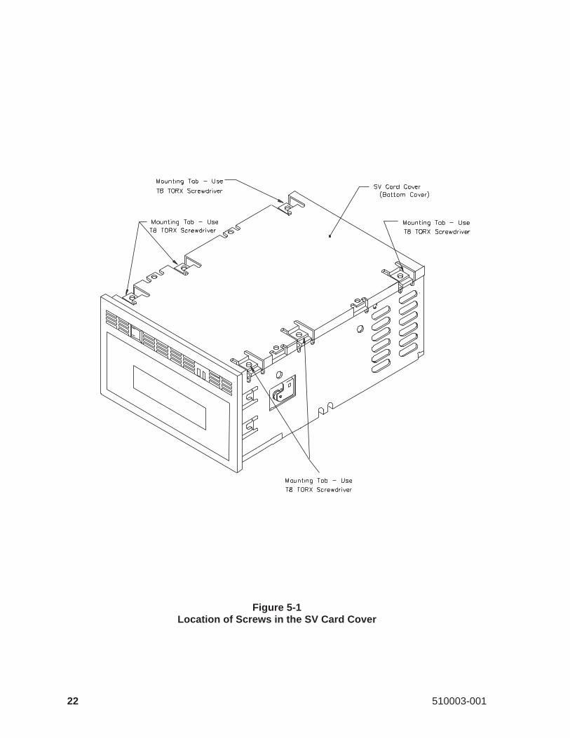
Figure 5-1Location of Screws in the SV Card Cover
22 510003-001
5 SV Card Cover Removal and Replacement
This section describes how to remove and replace the SV card cover.
5.1 SV Card Cover Removal
To remove the SV card cover, follow these steps:
1. Turn the EXB-8200 upside down so that the SV card cover is facing up.
2. Use a T8 TORX screwdriver to remove the six screws that hold the SVcard cover to the main housing. Figure 5-1 shows the locations of thesescrews.
3. After the screws are removed, lift the SV card cover off of the main hous-ing.
5.2 SV Card Cover Replacement
To replace the SV card cover, follow these steps:
1. Position the SV card cover with the tabs down and the stamped partnumber closest to the faceplate. All six of the mounting pads should bein contact with the SV card, and the holes should be lined up with thecorresponding holes in the SV card.
2. Secure the SV card cover to the main housing using the six T8 screwsthat were removed previously. Since you may need to move the coverslightly to align all of the mounting holes, do not tighten any of thescrews until all six have been started.
3. Tighten the mounting screws to 3.4 inch-pounds of torque.
CAUTION
Do not overtighten the screws.Overtightening these screws candamage the SV card or strip the holes in the main housing. If any ofthe screw holes in the main housing become stripped, the main hous-ing should be replaced.
May 1990 23
5 SV Card Cover Removal and Replacement
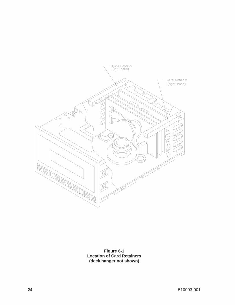
Figure 6-1Location of Card Retainers(deck hanger not shown)
24 510003-001
6 Card Retainer Removal and Replacement
This section describes how to remove and replace the card retainers.
6.1 Preparation
The card retainers are accessed at the top back of the EXB-8200. Before youremove the card retainers, remove the top cover as described in Section 4.
6.2 Remove Card Retainers
Figure 6-1 shows the locations of the card retainers. Note that there is a left-hand and a right-hand card retainer.
To remove the card retainers, grasp the ends of each card retainer betweenyour thumb and first finger and lift straight up. There should be no resistanceto the removal of the two card retainers.
6.3 Replace Card Retainers
The card retainers are designed as left-hand and right-hand components andwill fit correctly only one way. To replace the card retainers, follow thesesteps:
1. Place each card retainer so that only one card is in a slot, the deck hangerfits in the slot farthest away from the screw hole, and the screw hole islined up with the hole on the tab at the rear of the EXB-8200. If thecards are aligned squarely in the EXB-8200, the card retainers will slideon with little or no force.
2. Adjust the card positions slightly to get all the cards into their slots in theretainer.
3. After both card retainers are in place, exert downward pressure on thetop of both card retainers simultaneously. This will ensure that all cardsare properly seated in the EXB-8200.
6.4 Reassemble the EXB-8200
To reassemble the EXB-8200, replace the top cover as described in Section 4.
May 1990 25
6 Card Retainer Removal and Replacement
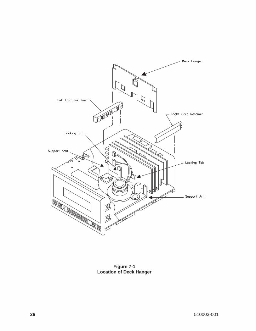
Figure 7-1Location of Deck Hanger
26 510003-001
7 Deck Hanger Removal and Replacement
This section describes how to remove and replace the deck hanger, whichseparates the card section of the EXB-8200 from the deck section. The deckhanger is installed into the deck hanger bracket, which is mounted along therear edge of the deck base. It prevents the RW wire harness from getting tan-gled in the moving parts of the deck.
7.1 Preparation
The deck hanger is mounted to the deck hanger bracket, which is attached tothe deck. To access the deck hanger, first remove these parts in the followingorder:
Top cover Section 4Card retainers Section 6
7.2 Deck Hanger Removal
To remove the deck hanger, follow these steps:
1. Locate the locking tabs that hold the deck hanger in place, as shown inFigure 7-1 The locking tabs protrude through the deck hanger from therear of the EXB-8200.
2. Press both tabs toward the rear of the EXB-8200 while pulling up on thedeck hanger. These tabs may be released simultaneously or one at a time.If they are pressed one at a time, pull up on the deck hanger after the firsttab is released and hold it in the unlocked position until the next tab is re-leased. The deck hanger can then be removed from the EXB-8200.
7.3 Deck Hanger Replacement
To replace the deck hanger, follow these steps:
1. Line up the deck hanger with the locking tabs behind it and the supportarms in front of it. The locking tabs and support arms work together tohold the deck hanger firmly in place.
2. Slide the deck hanger down between the locking tabs and support armsuntil it snaps into place. Very slight pressure is required.
May 1990 27
7 Deck Hanger Removal and Replacement
7.4 Reassemble the EXB-8200
To reassemble the EXB-8200, replace these parts in the following order:
Card retainers Section 6Top cover Section 4
28 510003-001
7 Deck Hanger Removal and Replacement
8 Edge Connector Mounted Card Removal and Replacement
This section describes how to remove and replace the edge connectormounted cards. These cards consist of the following:
DB/DS/DRMXDFCDRW.
8.1 MX Card Compatibility
This manual uses the termMX to refer to the MX card and to the MV and MScards, which are now obsolete.
The MX card and the DB or DR card are used in the single-ended SCSI ver-sion of the EXB-8200, while the MX card and the DS card are used in the dif-ferential SCSI version of the EXB-8200. The DB card has DIP switches forsetting the SCSI ID; the DR card has a remote connector for setting the SCSIID. The embed 3 version of the DS card implemented both DIP switches anda remote connector for setting the SCSI ID; previous versions of this cardhave DIP switches only.
The MV card is the original version of the MX card for single-ended SCSIconfigurations and is now obsolete. The MS card is the original version ofthe MX card for differential SCSI configurations and is now obsolete.
Be sure to check theEXB-8200 8mm Cartridge Tape Subsystem CompatibilityManual for proper card levels.
8.2 Preparation
The edge connector socket mounted cards plug into the SV card. To accessthese cards, first remove these parts in the following order:
Top cover Section 4Card retainers Section 6Deck hanger Section 7
The deck hanger needs to be removed only to disconnect the RW connectors.It does not need to be removed to remove any other card.
May 1990 29
8 Edge Connector Mounted Card Removal and Replacement
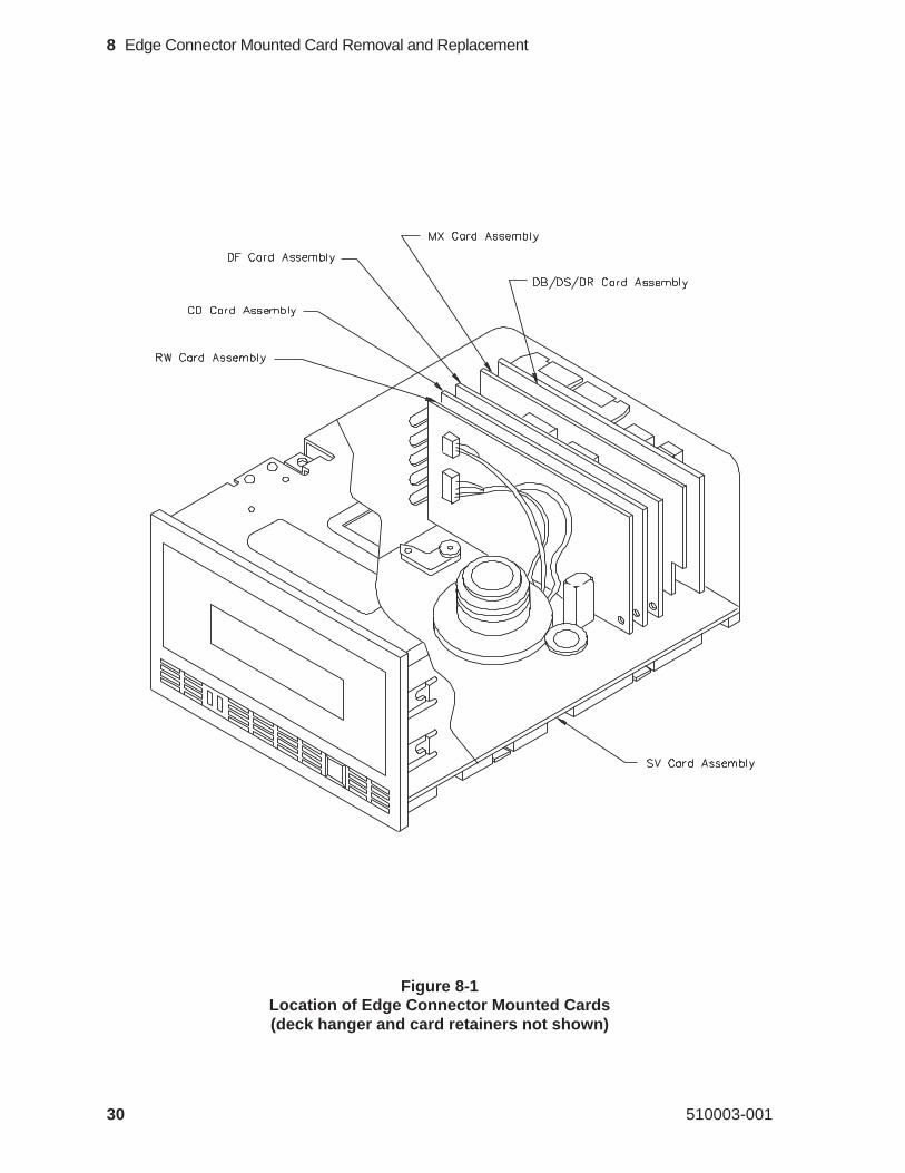
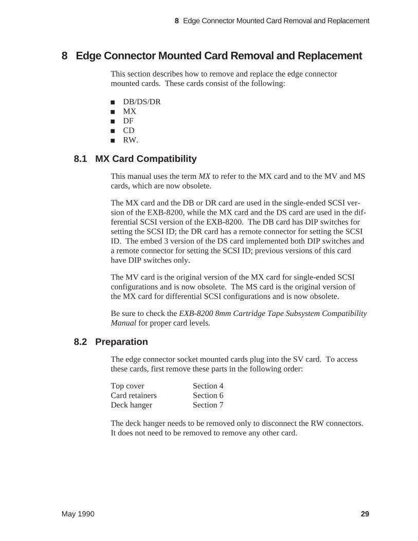
Figure 8-1Location of Edge Connector Mounted Cards(deck hanger and card retainers not shown)
30 510003-001
8 Edge Connector Mounted Card Removal and Replacement
8.3 Proper Handling of Printed Circuit Cards
When removing or inserting a card, hold the card on the PCB surface. Do nothold the components or connectors mounted on the card. Holding the compo-nents or connectors can damage the card. After removal, hold and place cardson their edges whenever possible.
8.4 Edge Connector Mounted Card Removal
Figure 8-1 shows the position of each edge connector mounted card. To re-move any of these cards, follow these steps:
Note: Before removing the RW card, remove the RW card connectors as ex-plained in Section 8.5.
1. Grasp the card between your thumb and first finger on both ends of thecard.
2. Lift the card straight up. This will require a reasonable amount of forcesince the card fits securely into the edge connector socket.
May 1990 31
8 Edge Connector Mounted Card Removal and Replacement
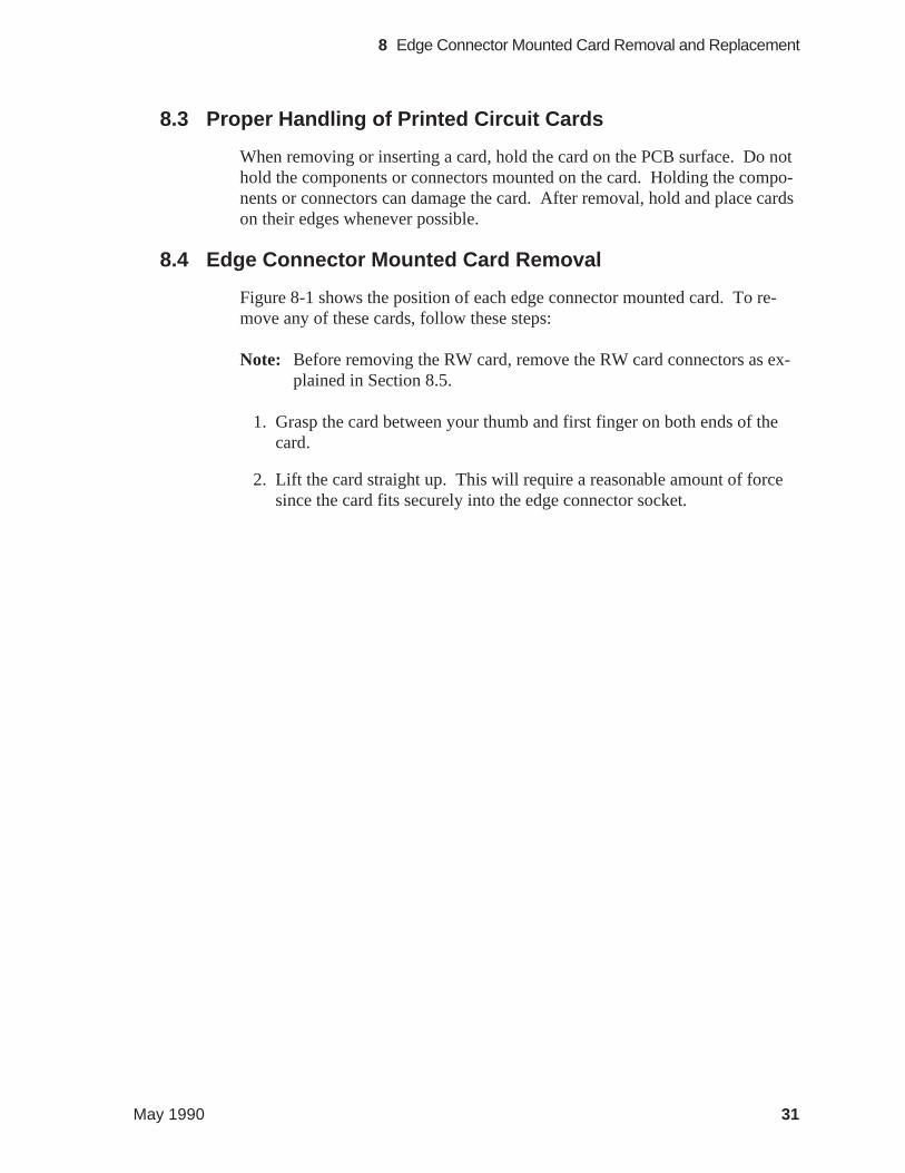
Figure 8-2Location of RW Card Wire Harness Connections
(deck hanger and card retainers not shown)
32 510003-001
8 Edge Connector Mounted Card Removal and Replacement
8.5 RW Card Connections
The RW card, shown in Figure 8-2, is slightly different from the other edgeconnector mounted cards. It has two wire harnesses connected to it, and it isthe only card with the component side facing the front of the EXB-8200.
To remove the RW card connections, follow these steps:
1. Remove the deck hanger to allow access to the wire harness connectorson the RW card.
2. Carefully separate the connections by sliding the plug portion to the rightusing a flat tool such as the blade of a straight blade screwdriver.
Then, you can remove the RW card as described in Section 8.4.
8.6 Replace Edge Connector Mounted Cards
To replace an edge connector mounted card, follow these steps:
1. Align the edge connector with the edge connector socket. Note that theedge connectors are uniquely keyed by offsetting their position on thecard. Ensure that the component side of the card is facing the rear of theEXB-8200.
Note: The components of the RW card should face the front of the EXB-8200.
2. Press on both ends of the card at the same time until the card is properlyseated in the card edge connector on the SV card.
3. If necessary, reconnect the wire harness to the RW card.
8.7 Reassemble the EXB-8200
To reassemble the EXB-8200, replace these parts in the following order:
Deck hanger Section 7Card retainers Section 6Top cover Section 4
May 1990 33
8 Edge Connector Mounted Card Removal and Replacement
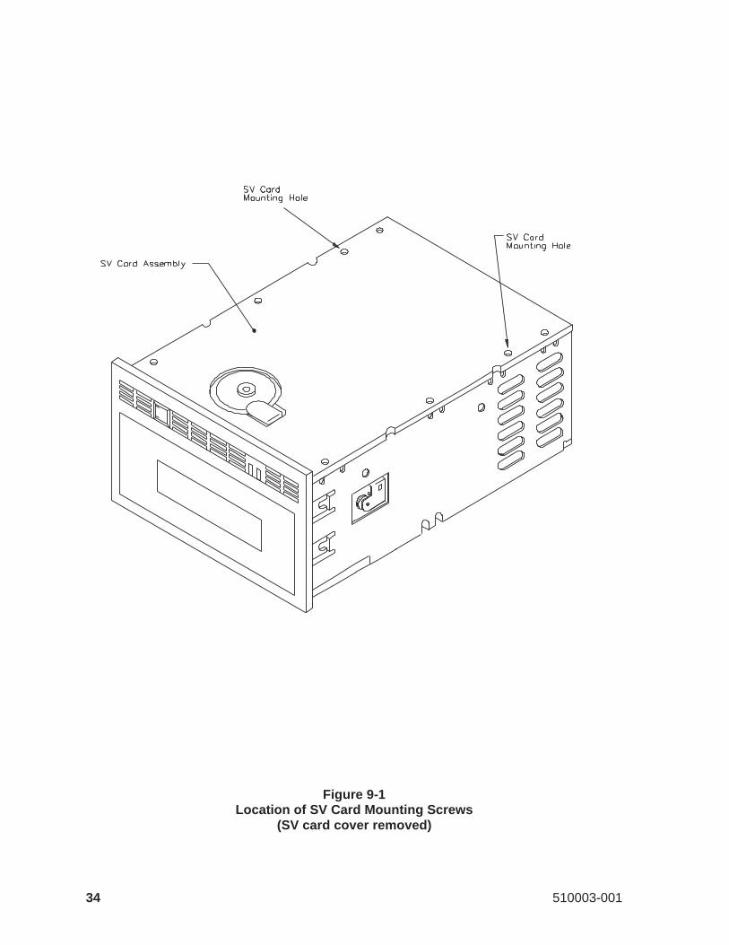
Figure 9-1Location of SV Card Mounting Screws
(SV card cover removed)
34 510003-001
9 SV Card Removal and Replacement
This section describes how to remove and replace the SV card.
9.1 Preparation
The SV card is the card into which the other cards (DB/DS/DR, MX, DF, CD,and RW) are inserted. The SV card performs the functions of a mother boardand contains the deck control circuitry. The SV card is mounted on the bot-tom of the EXB-8200. Before removing the SV card, remove these parts inthe following order:
Top cover Section 4Card retainers Section 6Deck hanger Section 7DB/DS/DR card Section 8MX card Section 8DF card Section 8CD card Section 8RW card Section 8SV card cover Section 5
9.2 Proper Handling of Printed Circuit Cards
When removing or inserting a card, hold the card on the PCB surface or thecard edges. Do not hold the components or connectors mounted on the card.Holding the components or connectors can damage the card. After removal,hold and place cards by their edges whenever possible.
9.3 Remove Mounting Screws
Use a T8 TORX screwdriver to remove the two screws that mount the SVcard to the main housing. Figure 9-1 shows the locations of the screws. Oncethese screws are removed, the SV card will be loose and ready for removal ofthe connectors.
May 1990 35
9 SV Card Removal and Replacement
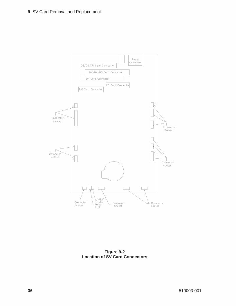
Figure 9-2Location of SV Card Connectors
36 510003-001
9 SV Card Removal and Replacement
9.4 Disconnect SV Card Connectors
CAUTION
Do not pull on the wires to remove the connectors or you may damagethe wires.
To disconnect the SV card connectors, follow these steps:
1. Turn the EXB-8200 so that it is resting on its side with the bottom facingtoward you and the front facing to your left.
2. Pull the SV card away from the main housing so that you can access theconnectors. There are 14 connectors and cables on the SV card attachedto various components on the deck. Figure 9-2 shows the location ofthese connectors on the SV card.
May 1990 37
9 SV Card Removal and Replacement
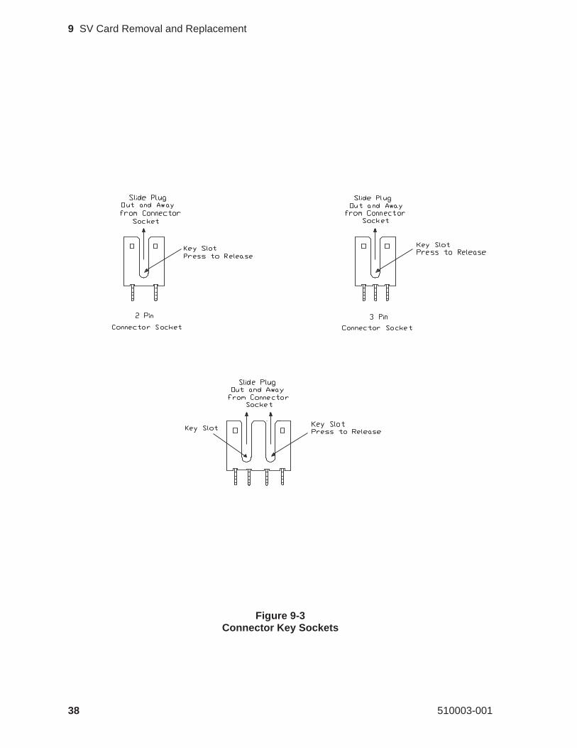
Figure 9-3Connector Key Sockets
38 510003-001
9 SV Card Removal and Replacement
3. Starting with the connectors closest to the rear of the EXB-8200, removeall of the connectors along the edge facing you. Use the points on a pairof tweezers to push down on the bottom of the key portion of the connec-tor plug, then push the plug away from the SV card mounted socket.Each connector socket has either one or two key slots. On those connec-tors with two keys, alternate pushing on each key so that the connector isremoved evenly from the socket. See Figure 9-3.
4. Turn the EXB-8200 so that it is resting on its back with the front facingup.
5. Pull the SV card away from the main housing and disconnect the plugsalong the front edge of the card.
6. Turn the EXB-8200 again so that the bottom of the EXB-8200 is still fac-ing you and the front faces to your right.
7. Disconnect all plugs along the edge of the card.
8. Once the electrical connections are disconnected, pull the SV card awayfrom the main housing.
May 1990 39
9 SV Card Removal and Replacement
9.5 Reconnect the SV Card Connections
To reconnect the SV card connections, follow the instructions for removingthe SV card connections in reverse order. The connections are easiest to re-connect if you start at the rear of the EXB-8200 and work around to the front.Then, work across the front and back toward the rear, ending with the rearconnector on the right-hand side. Ensure that the connectors are fully seated.
CAUTION
Be sure to plug the connectors into the correct sockets. The connec-tors and the sockets are color coded or sized differently to help you de-termine which connector goes with which socket. In the front of theEXB-8200, there are two connectors with three pins. At this location,be especially careful to insert the yellow connector into the yellowsocket and the white connector into the white socket.
9.6 Reattach the SV Card to the Main Housing
To reattach the SV card to the main housing, follow these steps:
1. Turn the EXB-8200 upside down with the front of the EXB-8200 facingyou.
2. Mount the SV card to the main housing using the two screws that wereremoved from it. Before tightening the screws, carefully inspect theedges of the SV card to ensure that no wires are caught between the SVcard and the main housing. Tighten the screws to 3.4 inch-pounds oftorque.
CAUTION
Do not overtighten the screws.Overtightening these screws candamage the SV card.
3. If the SV card was replaced with another card, check the head sync ad-justment. Reset the head sync if necessary using the procedure describedin Section 18.
40 510003-001
9 SV Card Removal and Replacement
9.7 Reassemble the EXB-8200
To reassemble the EXB-8200, replace these parts in the following order:
SV card cover Section 5RW card Section 8CD card Section 8DF card Section 8MX card Section 8DB/DS/DR card Section 8Deck hanger Section 7Card retainers Section 6Top cover Section 4
May 1990 41
9 SV Card Removal and Replacement
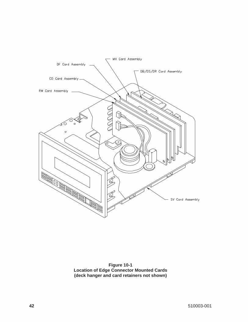
Figure 10-1Location of Edge Connector Mounted Cards(deck hanger and card retainers not shown)
42 510003-001
10 MX EPROM Removal and Replacement
This section describes how to remove and replace the EPROM on the MXcard. Figure 10-1 shows the location of the MX card.
Note: This manual uses the termMX to refer to the MX card and to the MVand MS cards, which are now obsolete. Refer to Section 8.1 for moreinformation.
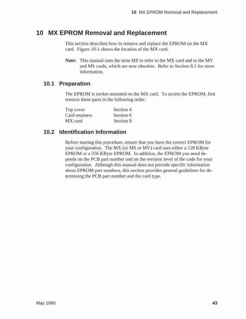
10.1 Preparation
The EPROM is socket mounted on the MX card. To access the EPROM, firstremove these parts in the following order:
Top cover Section 4Card retainers Section 6MX card Section 8
10.2 Identification Information
Before starting this procedure, ensure that you have the correct EPROM foryour configuration. The MX (or MS or MV) card uses either a 128 KByteEPROM or a 256 KByte EPROM. In addition, the EPROM you need de-pends on the PCB part number and on the revision level of the code for yourconfiguration. Although this manual does not provide specific informationabout EPROM part numbers, this section provides general guidelines for de-termining the PCB part number and the card type.
May 1990 43
10 MX EPROM Removal and Replacement
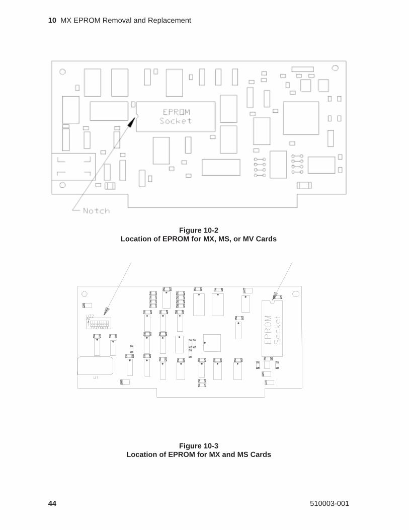
Figure 10-2Location of EPROM for MX, MS, or MV Cards
Figure 10-3Location of EPROM for MX and MS Cards
44 510003-001
10 MX EPROM Removal and Replacement
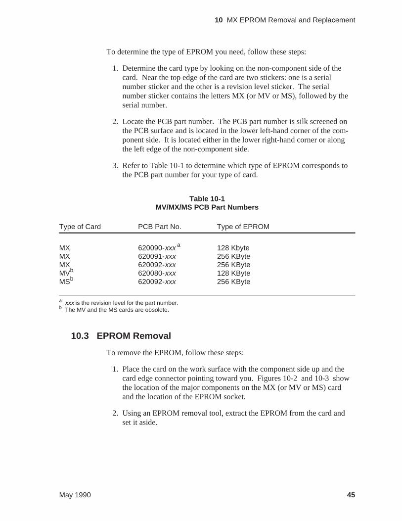
To determine the type of EPROM you need, follow these steps:
1. Determine the card type by looking on the non-component side of thecard. Near the top edge of the card are two stickers: one is a serialnumber sticker and the other is a revision level sticker. The serialnumber sticker contains the letters MX (or MV or MS), followed by theserial number.
2. Locate the PCB part number. The PCB part number is silk screened onthe PCB surface and is located in the lower left-hand corner of the com-ponent side. It is located either in the lower right-hand corner or alongthe left edge of the non-component side.
3. Refer to Table 10-1 to determine which type of EPROM corresponds tothe PCB part number for your type of card.
Type of Card PCB Part No. Type of EPROM
MX 620090-xxx a 128 KbyteMX 620091-xxx 256 KByteMX 620092-xxx 256 KByteMVb 620080-xxx 128 KByteMSb 620092-xxx 256 KByte
a xxx is the revision level for the part number.b The MV and the MS cards are obsolete.
10.3 EPROM Removal
To remove the EPROM, follow these steps:
1. Place the card on the work surface with the component side up and thecard edge connector pointing toward you. Figures 10-2 and 10-3 showthe location of the major components on the MX (or MV or MS) cardand the location of the EPROM socket.
2. Using an EPROM removal tool, extract the EPROM from the card andset it aside.
Table 10-1MV/MX/MS PCB Part Numbers
May 1990 45
10 MX EPROM Removal and Replacement
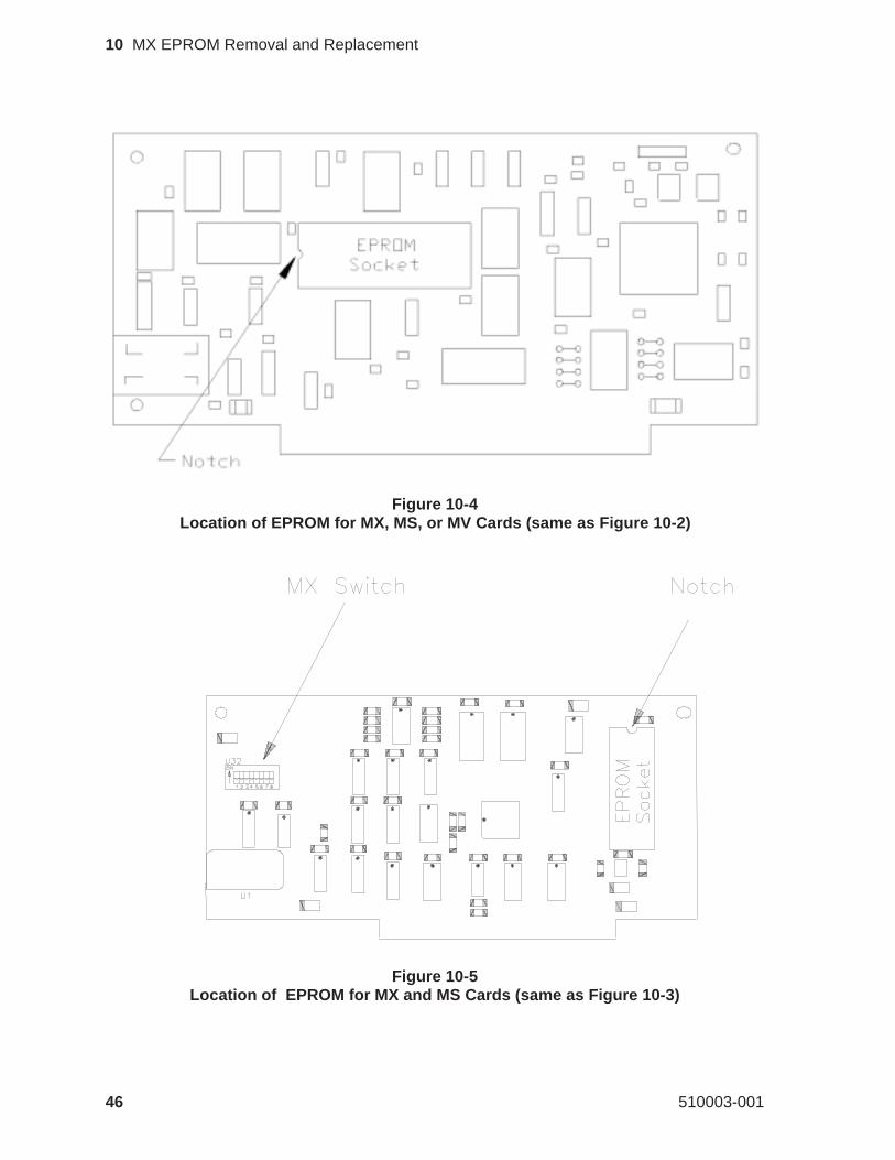
Figure 10-4Location of EPROM for MX, MS, or MV Cards (same as Figure 10-2)
Figure 10-5Location of EPROM for MX and MS Cards (same as Figure 10-3)
46 510003-001
10 MX EPROM Removal and Replacement
10.4 EPROM Installation
CAUTION
Be sure to install the correct EPROM on the card. Before installingthe EPROM, see Section 10.2 for information about identifyingEPROMs and cards correctly.
To install the EPROM if an EPROM insertion tool is available, follow thesesteps:
1. Select the EPROM to be installed and orient the notch in the EPROMwith the notch in the EPROM socket on the card, as shown in either Fig-ure 10-4 or Figure 10-5.
2. Use the EPROM insertion tool to insert the new EPROM.
To install the EPROM if an EPROM insertion tool is not available, followthese steps:
1. Select the EPROM to be installed and position it on the socket carefully,checking to ensure that each pin on the EPROM is aligned with a hole inthe EPROM socket.
2. Place both thumbs on top of the EPROM and press it into the socket. Becareful to provide even pressure on the top of the EPROM so that allpins are inserted at the same time. Uneven pressure can result in theEPROM being only partially inserted and in bent pins on the EPROM.
3. Visually inspect the EPROM to ensure that all of the pins have been cor-rectly inserted. If the EPROM is not fully seated in the socket, apply ad-ditional pressure to bottom out all pins on the EPROM into the socket.
4. If any of the pins are bent, remove the EPROM. Then, attempt tostraighten the pins and reinsert the EPROM. Follow the previous stepsto remove, insert, and inspect the EPROM.
Note: Do not use the EPROM if any of the pins are broken.
May 1990 47
10 MX EPROM Removal and Replacement
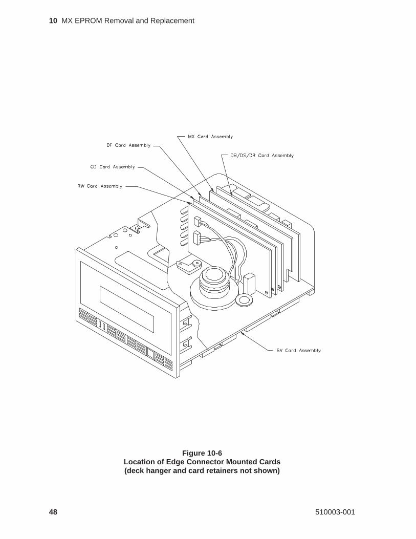
Figure 10-6Location of Edge Connector Mounted Cards(deck hanger and card retainers not shown)
48 510003-001
10 MX EPROM Removal and Replacement
10.5 Reassemble the EXB-8200
To reassemble the EXB-8200, replace these parts in the following order:
MX card Section 8Card retainers Section 6Top cover Section 4
May 1990 49
10 MX EPROM Removal and Replacement
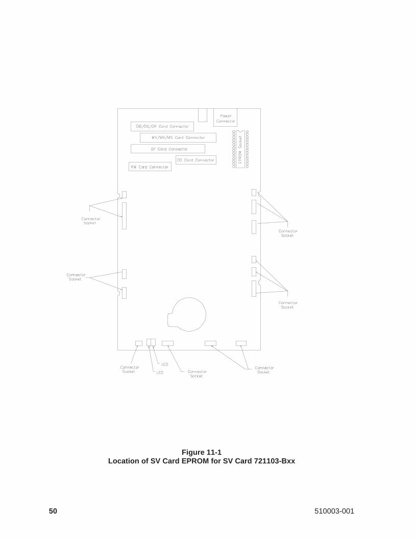
Figure 11-1Location of SV Card EPROM for SV Card 721103-Bxx
50 510003-001
11 SV Card EPROM Removal and Replacement
This section describes how to remove and replace the EPROM contained onthe SV card. There are two different types of SV cards: 721103-Bxxand721102-Bxx. The steps for replacing the EPROM on SV card 721103-Bxxaredescribed first, followed by the steps for replacing the EPROM on SV card721102-Bxx.
11.1 Proper Handling of Printed Circuit Cards
When removing or inserting a card, hold the card on the PCB surface. Do nothold the components or connectors mounted on the card. Holding the compo-nents or connectors can damage the card. After removal, hold and place cardson their edges whenever possible.
11.2 Preparation for SV Card 721103-Bxx
The SV EPROM is socket mounted on the SV card. To access the SV cardEPROM, first remove these parts in the following order:
Top cover Section 4Card retainers Section 6Deck hanger Section 7DB/DS/DR card Section 8MX card Section 8DF card Section 8CD card Section 8RW card Section 8
Note: Do not remove SV card 721103-Bxx to replace the EPROM.
11.3 EPROM Removal for SV Card 721103-Bxx
To remove the EPROM, follow these steps:
1. Place the EXB-8200 on the work surface with the front facing you. Lo-cate the EPROM (see Figure 11-1).
2. Remove the EPROM using an appropriate EPROM removal tool.
May 1990 51
11 SV Card EPROM Removal and Replacement
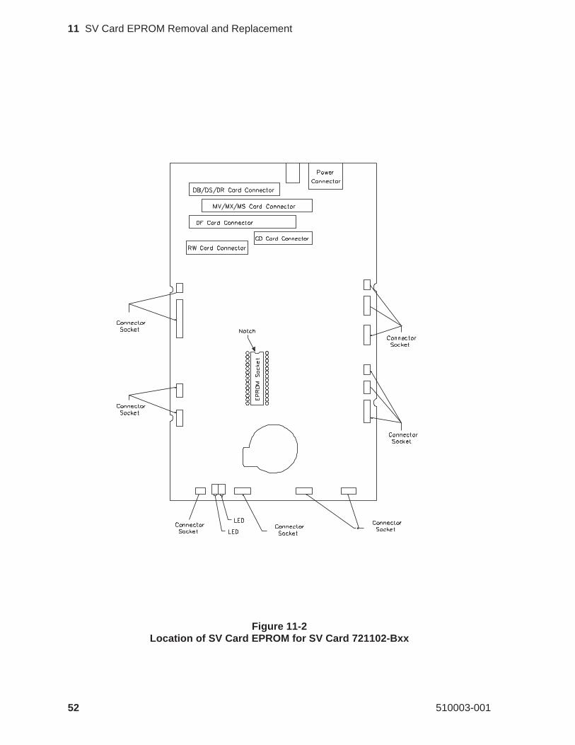
Figure 11-2Location of SV Card EPROM for SV Card 721102-Bxx
52 510003-001
11 SV Card EPROM Removal and Replacement
11.4 Preparation for SV Card 721102-Bxx
To access the EPROM on the 721102-BxxSV card, remove all of the itemsmentioned in Section 11.2. Then, remove these parts in the following order:
SV card cover Section 4SV card Section 8
11.5 EPROM Removal for SV Card 721102-Bxx
To remove the EPROM, follow these steps:
1. Place the SV card on the work surface with the component side up andthe front edge of the card facing you. The front edge of the SV card isidentified by the two LEDs and the circular cutout in the card.Figure 11-2 shows the location of the major components on the card andthe location of the EPROM socket.
2. Using an EPROM removal tool, extract the EPROM from the SV cardand set it aside.
11.6 EPROM Installation
To install the EPROM if an EPROM insertion tool is available, follow thesesteps:
1. Select the EPROM to be installed and orient it with the notch toward therear edge of the SV card. This will correspond to the notch in theEPROM socket on the SV card.
2. Use the EPROM insertion tool to insert the EPROM.
May 1990 53
11 SV Card EPROM Removal and Replacement
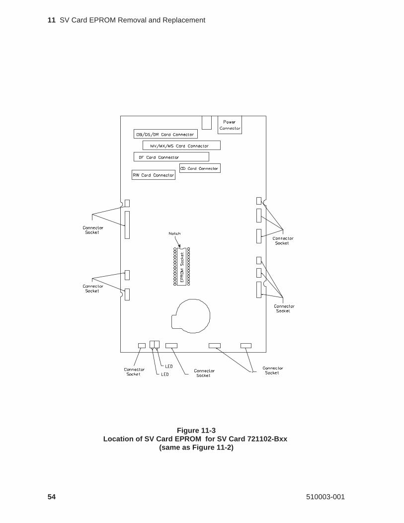
Figure 11-3Location of SV Card EPROM for SV Card 721102-Bxx
(same as Figure 11-2)
54 510003-001
11 SV Card EPROM Removal and Replacement
To install the EPROM if an EPROM insertion tool is not available, followthese steps:
1. Carefully position the EPROM on the socket. Check to ensure that eachpin on the EPROM is aligned with a hole in the EPROM socket on theSV card.
2. Place both thumbs on top of the EPROM and press it into the socket. Becareful to provide even pressure on the top of the EPROM so that allpins are inserted at the same time. Uneven pressure can result in theEPROM being only partially inserted and in bent pins on the EPROM.
3. Visually inspect the EPROM to ensure that all of the pins have been cor-rectly inserted into the socket. If the EPROM is not fully seated in thesocket, apply additional pressure to bottom out all pins into the socket.
4. If any of the pins are bent, remove the EPROM. Then, attempt tostraighten the pins and reinsert the EPROM. Follow the previous stepsto remove, insert, and inspect the EPROM.
Note: Do not use the EPROM if any of the pins are broken.
11.7 Reassemble the EXB-8200
To reassemble the EXB-8200, replace these parts in the following order:
SV card (for part number 721102-Bxx) Section 9SV card cover (for part number 721102-Bxx) Section 5RW card Section 8CD card Section 8DF card Section 8MX card Section 8DB/DS/DR card Section 8Deck hanger Section 7Card retainers Section 6Top cover Section 4
May 1990 55
11 SV Card EPROM Removal and Replacement
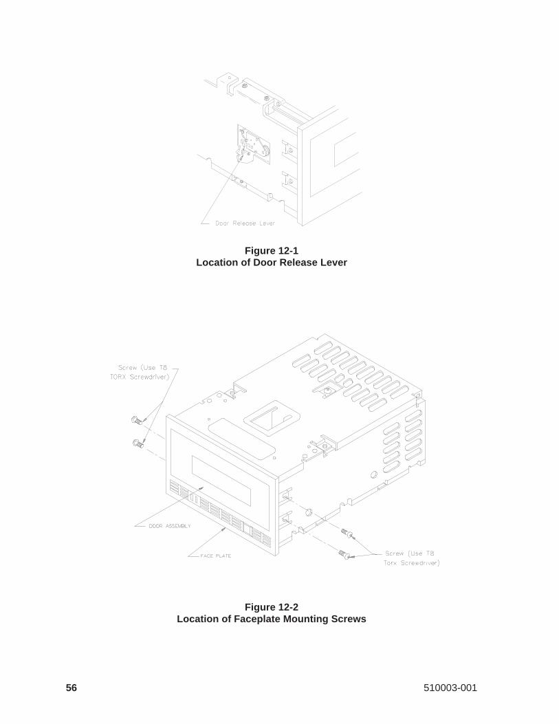
Figure 12-1Location of Door Release Lever
Figure 12-2Location of Faceplate Mounting Screws
56 510003-001
12 Faceplate Removal and Replacement
This section describes how to remove and replace the faceplate.
12.1 Faceplate Removal
To remove the faceplate, follow these steps:
1. To avoid damaging tape, ensure that there is no data cartridge in theEXB-8200.
2. Open the door on the EXB-8200 using an appropriate tool, such as asmall screwdriver, to move the door release lever toward the front of theEXB-8200. Figure 12-1 shows the location of the door release lever.The amount of force required to activate the lever is slight and the move-ment is less than 1/8 of an inch. Be careful not to damage the smallswitch contacts next to the door release lever.
3. Using a T8 TORX screwdriver, loosen the four faceplate mountingscrews, but do not completely remove them. Figure 12-2 shows the loca-tion of these screws.
4. Position the EXB-8200 so that it is resting on the rear of the main hous-ing, with the front pointing up and the door open.
5. Move the faceplate away from the main housing. Close the door par-tially, so you can slide the faceplate off of the mounting screws andaround the door.
May 1990 57
12 Faceplate Removal and Replacement
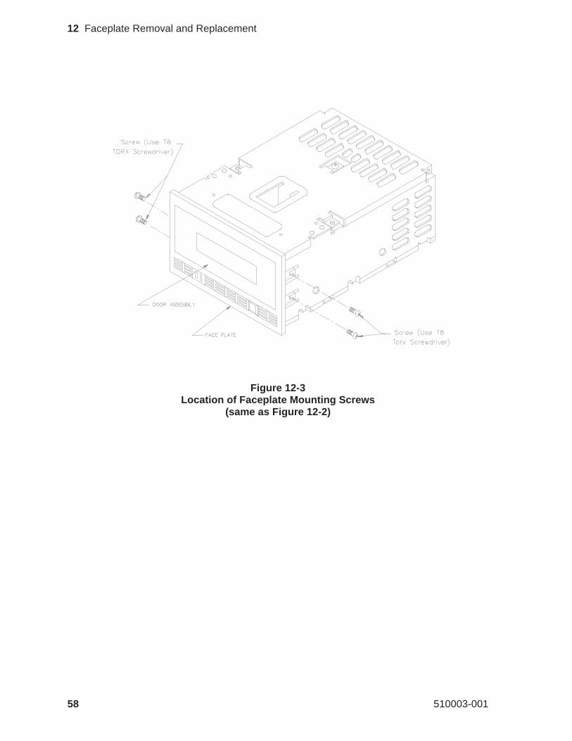
Figure 12-3Location of Faceplate Mounting Screws
(same as Figure 12-2)
58 510003-001
12 Faceplate Removal and Replacement
12.2 Faceplate Replacement
To replace the faceplate, follow these steps:
1. Position the EXB-8200 on the work surface so that it is resting on therear of the main housing with the door open and facing up.
2. Close the door partially so that you can slide the faceplate around thedoor and align it with the four mounting screws (see Figure 12-3).
3. Position the faceplate so that the mounting tabs are under the four mount-ing screws and the faceplate is flush with the door when it is closed.
4. Tighten the mounting screws until they are snug.
CAUTION
Do not overtighten the screws.Overtightening these screws candamage the faceplate mounting tabs or strip the screw holes in themain housing.
May 1990 59
12 Faceplate Removal and Replacement
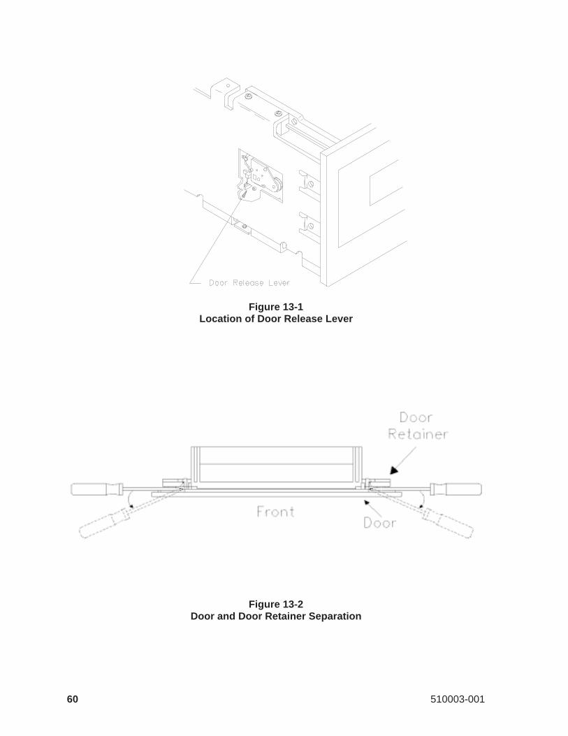
Figure 13-1Location of Door Release Lever
Figure 13-2Door and Door Retainer Separation
60 510003-001
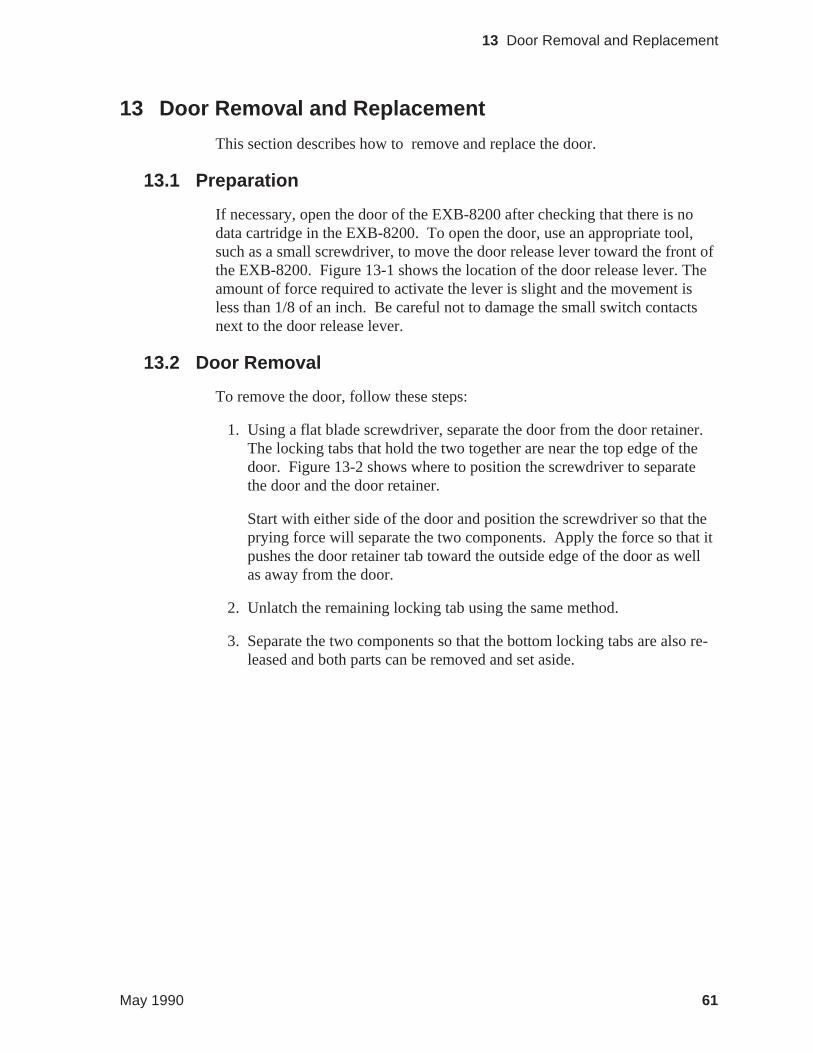
13 Door Removal and Replacement
This section describes how to remove and replace the door.
13.1 Preparation
If necessary, open the door of the EXB-8200 after checking that there is nodata cartridge in the EXB-8200. To open the door, use an appropriate tool,such as a small screwdriver, to move the door release lever toward the front ofthe EXB-8200. Figure 13-1 shows the location of the door release lever. Theamount of force required to activate the lever is slight and the movement isless than 1/8 of an inch. Be careful not to damage the small switch contactsnext to the door release lever.
13.2 Door Removal
To remove the door, follow these steps:
1. Using a flat blade screwdriver, separate the door from the door retainer.The locking tabs that hold the two together are near the top edge of thedoor. Figure 13-2 shows where to position the screwdriver to separatethe door and the door retainer.
Start with either side of the door and position the screwdriver so that theprying force will separate the two components. Apply the force so that itpushes the door retainer tab toward the outside edge of the door as wellas away from the door.
2. Unlatch the remaining locking tab using the same method.
3. Separate the two components so that the bottom locking tabs are also re-leased and both parts can be removed and set aside.
May 1990 61
13 Door Removal and Replacement
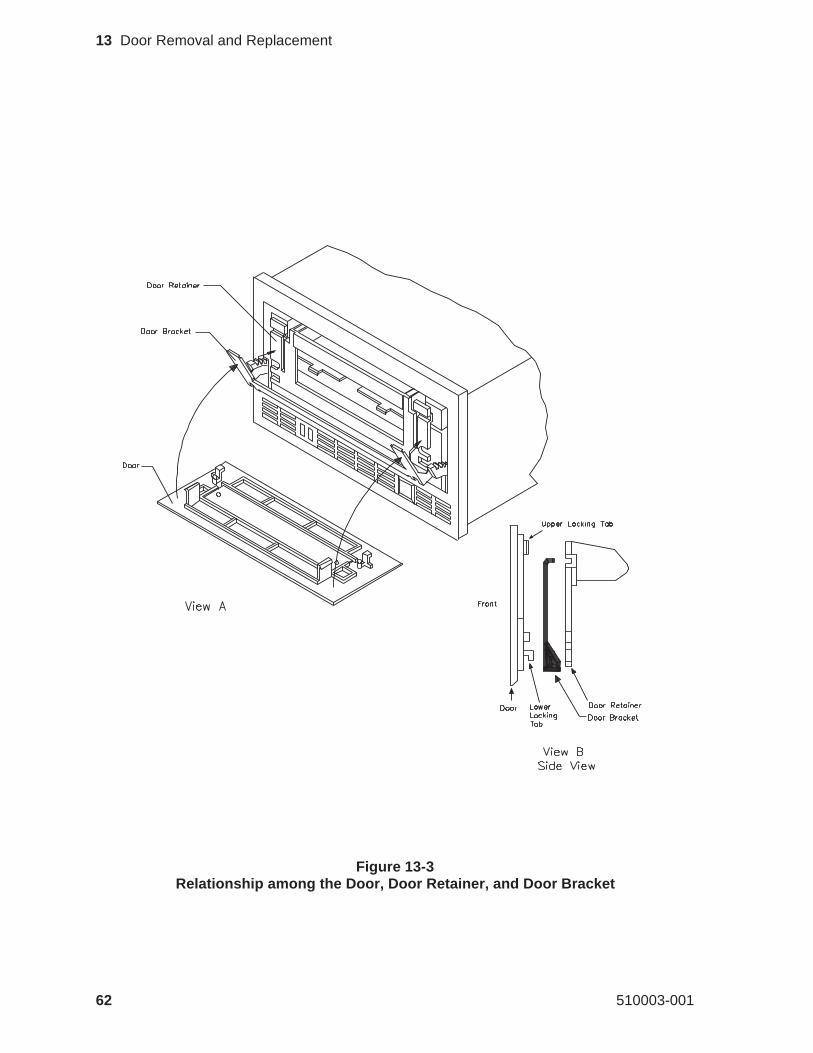
Figure 13-3Relationship among the Door, Door Retainer, and Door Bracket
62 510003-001
13 Door Removal and Replacement
13.3 Door Replacement
Practice assembling the door and the door retainer independently of theEXB 8200 several times before attempting to put them on the EXB-8200. Besure to observe the final relationship of all of the locking tabs so that it is clearhow they should look when they are placed on the door mechanism. View Ain Figure 13-3 shows how the door, the door retainer, and the door bracket arepositioned on the EXB-8200. View B shows a side view of the door, the doorbracket, and the door retainer.
To replace the door, follow these steps:
1. If necessary, open the door mechanism on the EXB-8200 after checkingthat there is no data cartridge in the EXB-8200.
2. Position the door on the arms of the door bracket so that the bottom lock-ing tabs on the door are in the notches on the bottom of the door bracket.
3. Hold the door in position on the door bracket with the thumb and first fin-ger of one hand and position the door retainer so that the locking tabnotches on the bottom of the door retainer are by the locking tabs on thedoor.
4. Squeeze the door and door retainer together using the thumb and first fin-ger of each hand so that the bottom notches snap together with the lock-ing tabs. Apply the pressure so that the door retainer moves in and upunder the locking tabs.
5. Squeeze the door and door retainer together at the top edge to engage thetop locking tabs.
6. Inspect the door to make sure all tabs are in the correct position. If oneof the bottom tabs is not in its correct position, separate the door and thedoor retainer and restart the replacement procedure.
May 1990 63
13 Door Removal and Replacement
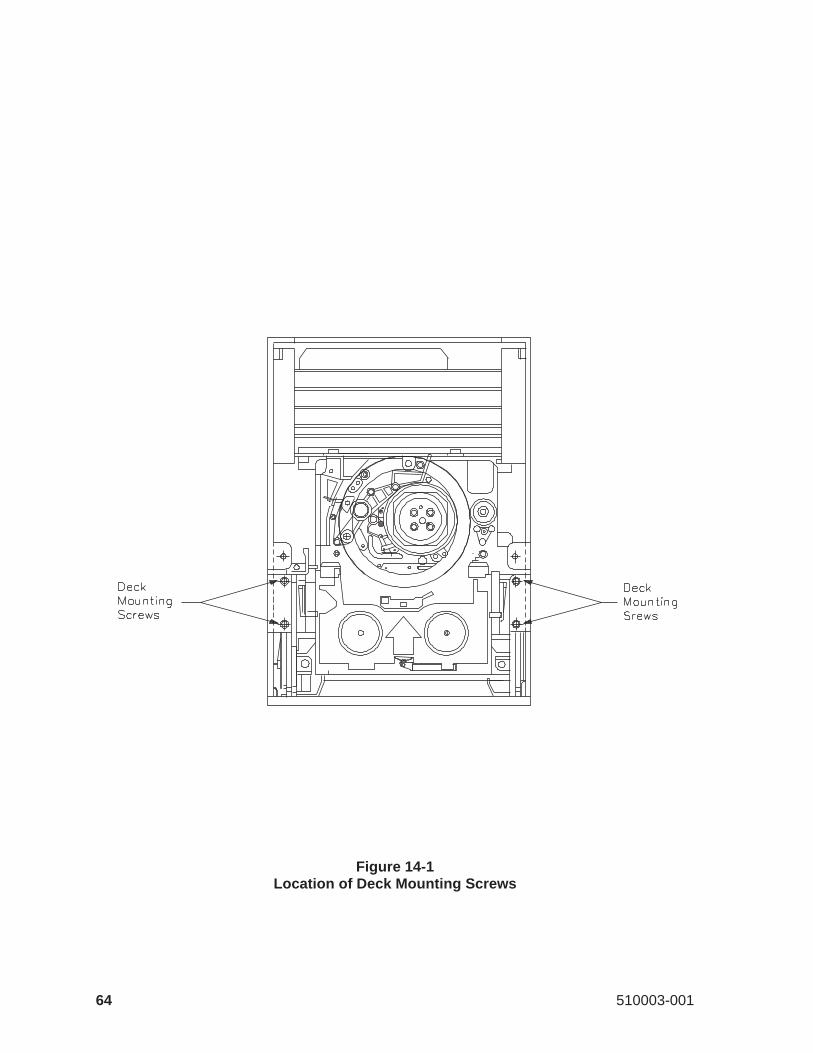
Figure 14-1Location of Deck Mounting Screws
64 510003-001
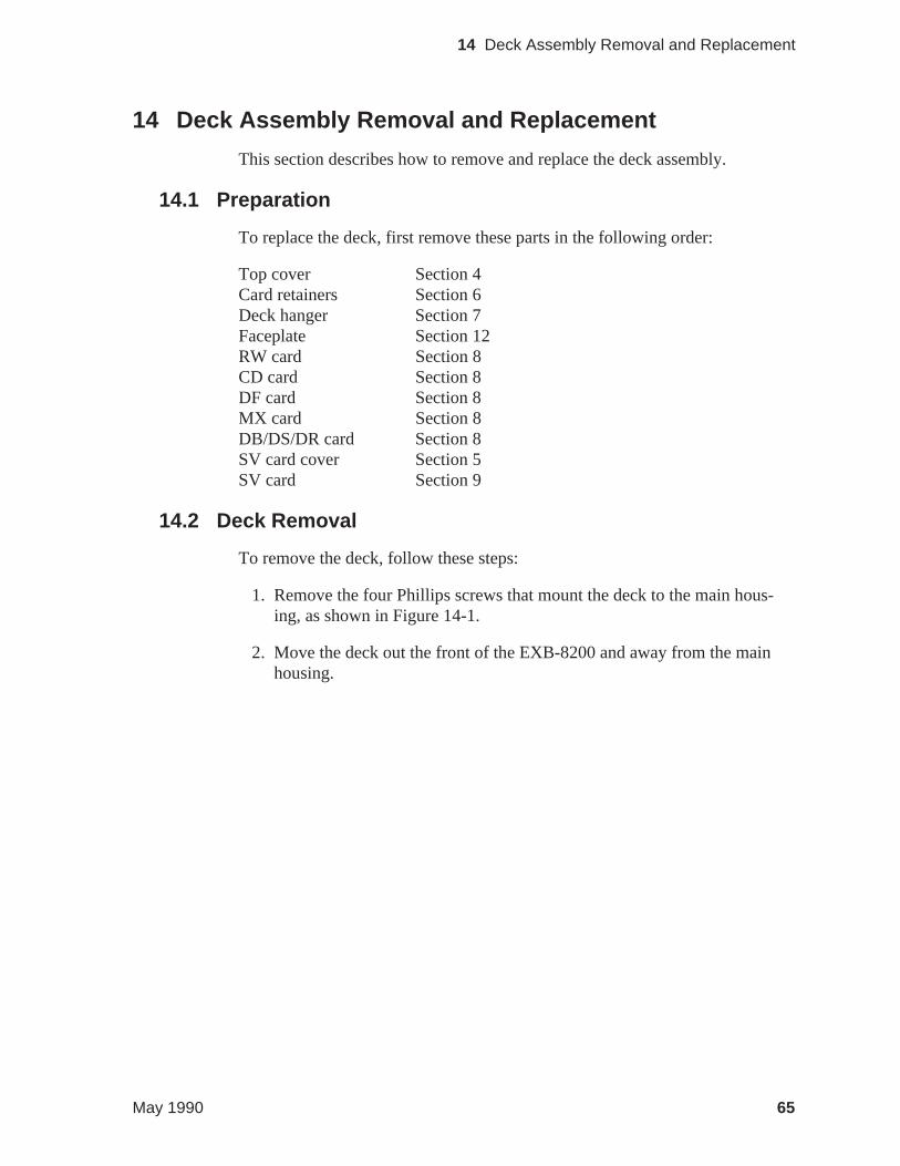
14 Deck Assembly Removal and Replacement
This section describes how to remove and replace the deck assembly.
14.1 Preparation
To replace the deck, first remove these parts in the following order:
Top cover Section 4Card retainers Section 6Deck hanger Section 7Faceplate Section 12RW card Section 8CD card Section 8DF card Section 8MX card Section 8DB/DS/DR card Section 8SV card cover Section 5SV card Section 9
14.2 Deck Removal
To remove the deck, follow these steps:
1. Remove the four Phillips screws that mount the deck to the main hous-ing, as shown in Figure 14-1.
2. Move the deck out the front of the EXB-8200 and away from the mainhousing.
May 1990 65
14 Deck Assembly Removal and Replacement
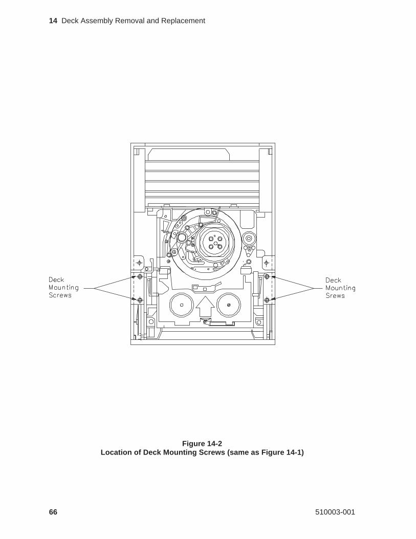
Figure 14-2Location of Deck Mounting Screws (same as Figure 14-1)
66 510003-001
14 Deck Assembly Removal and Replacement
14.3 Deck Replacement
To replace the deck, follow these steps:
1. Set the new deck in place and start the four mounting screws to hold thedeck in place while reassembling the EXB-8200. Do not tighten thesescrews at this time.
2. Mount the door assembly from the old deck on the new deck (see Sec-tion 13).
3. Install the faceplate on the main housing (see Section 12).
4. Close the door to the deck and position the deck so that the door is flushwith the faceplate.
5. Tighten the deck mounting screws to 1.7 inch-pounds of torque.
CAUTION
Do not overtighten the screws.Overtightening these screws canstrip the screw holes in the new deck.
14.4 Reassemble the EXB-8200
To reassemble the EXB-8200, replace these parts in the following order:
SV card Section 9SV card cover Section 5DB/DS/DR card Section 8MX card Section 8DF card Section 8CD card Section 8RW card Section 8Deck hanger Section 7Card retainers Section 6Top cover Section 4
May 1990 67
14 Deck Assembly Removal and Replacement
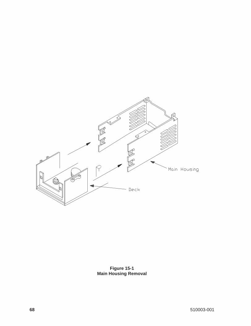
Figure 15-1Main Housing Removal
68 510003-001
15 Main Housing Removal and Replacement
This section describes how to remove and replace the main housing.
15.1 Preparation
To replace the main housing, first remove these parts in the following order:
Top cover Section 4Card retainers Section 6Faceplate Section 12SV card cover Section 5
Note: You must remove the SV card mounting screws (see Section 9.3), butthe SV card can remain in place. You should also remove the deckmounting screws (see Section 14.2), but there is no need to remove thedeck.
15.2 Main Housing Removal
After the main housing has been separated from all other assemblies and com-ponents, the main housing is ready for removal. To remove the main housing,follow these steps:
1. Grasp the main housing by the sides toward the front.
2. Spread the sides of the main housing apart.
3. Push the main housing away from the rest of the EXB-8200 until it iscompletely separate from the deck and cards, as shown in Figure 15-1.
May 1990 69
15 Main Housing Removal and Replacement
15.3 Main Housing Replacement
To replace the main housing, follow these steps:
1. Grasp the main housing by the sides at the front.
2. Spread the sides of the main housing apart.
3. Pull the main housing around the deck and cards until it is in place.
4. Inspect the mounting tabs for the SV card cover to ensure that they arepositioned so that the SV card and SV card cover can be mounted to themain housing properly. The screws for the SV card cover should gothrough the SV card cover and SV card before they go into the mainhousing.
15.4 Reassemble the EXB-8200
To reassemble the EXB-8200, replace these parts in the following order:
Deck assembly Section 14SV card Section 9SV card cover Section 5Card retainers Section 6Faceplate Section 12Top cover Section 4
70 510003-001
15 Main Housing Removal and Replacement
16 Cleaning Procedure
This section describes how to clean an EXB-8200.
16.1 Accepted Procedures and Products
The only cleaning material authorized for use with the EXB-8200 is the EX-ABYTE 8mm Tape Subsystem Cleaning Cartridge 727113 (3 cleanings).
Cloth swabs, cotton swabs, and cleaning agents are not accepted for use andwill void the warranty on the EXB-8200.
16.2 Cleaning Intervals
The EXABYTE Cleaning Cartridge is designed as a preventive maintenanceproduct. Use it at regular intervals based on tape drive use. Under normal en-vironmental conditions, use the cleaning cartridge once a month or after ap-proximately 30 gigabytes of data transfer or 30 tape motion hours, whicheveroccurs first. If the EXB-8200 is experiencing read/write performance prob-lems, perform one or two cleaning passes at that time.
Note: For planning purposes, one gigabyte of data is transferred for everyhour of continuous streaming operation.
16.3 Minimum Firmware Level Required
The EXABYTE Cleaning Cartridge will work properly with all EXB-8200sthat have MX processor firmware of at least 4$22 and SV processor firmwareof at least B016. Inserting a cleaning tape into EXB-8200s below these firm-ware levels causes the EXB-8200 to identify the cleaning tape as a data tape.If this occurs, the EXB-8200 will load the cleaning tape and show Readystatus (green LED lit). Press the unload button to unload the cleaning car-tridge.
May 1990 71
16 Cleaning Procedure
16.4 Cleaning Action Performed by Cartridge
When a cleaning cartridge is inserted into an EXB-8200 with the proper firm-ware levels, the cleaning tape is loaded into the tape path and moved forwardfor approximately 15 seconds. At the end of this time, the cleaning tape isdrawn back into the cartridge and the cartridge is ejected. The EXB-8200 isready for use at this point.
16.5 Usage and Reusage
The EXB-8200 8mm Tape Subsystem Cleaning Cartridge is designed forthree uses and then disposal. The cleaning tape should never be rewound orreused since the chances of reintroducing contaminants are very high. Firm-ware 4$22 and above are designed to prevent the EXB-8200 from rewindingcleaning tapes.
16.6 Cleaning Instructions
To clean an EXB-8200, follow these steps:
1. Apply power to the EXB-8200. When the power-on cycle is complete,open the door and remove any data cartridge from the EXB-8200. Leavethe door open.
2. Place the cleaning cartridge into the EXB-8200 and close the door.
The remainder of the cleaning process is automatically performed by theEXB-8200. When the cleaning process is complete, the cleaning car-tridge is automatically unloaded and ejected from the EXB-8200. Theaverage cleaning cycle is 15 seconds.
3. Record the date on the cartridge label.
4. Store the cleaning cartridge for future use.
Note: To prevent contamination of the EXB-8200, do not rewind the clean-ing cartridge or use it more than three times.
72 510003-001
16 Cleaning Procedure
17 Tape Removal Procedure
This section describes how to remove a data cartridge that is loaded in thetape path around the rotating head assembly of a nonfunctioning EXB-8200.Use this procedure only as a last option when it is necessary to preserve thedata on the tape.
Before using this procedure and if there are any questions about this proce-dure, contact EXABYTE Technical Support. Technical Support will attemptto provide alternate methods for recovering the data cartridge.
IMPORTANT
EXABYTE Corporation does not assume responsibility for any dam-age to the EXB-8200, the data cartridge, or media or for the loss ofany data resulting from this procedure. Any damage to theEXB-8200 caused by this procedure will be repaired as a nonwarrantyrepair and may void the existing warranty for the EXB-8200.
17.1 Preparation
Before attempting this procedure, remove and reapply power to the EXB-8200 in an attempt to clear a possible hang condition. If the green LED is lit,indicating Ready status, push the unload button or issue a SCSI UNLOADcommand. If the green LED is not lit, continue with the instructions in thissection.
17.2 Definitions
Non-functioning EXB-8200. For the purposes of this procedure, a non-func-tioning EXB-8200 is an EXB-8200 that fails to execute the rewind/unload op-eration on power up.
Rewind/Unload Operation. The rewind/unload operation is the operation inwhich the tape is returned to the supply reel of the data cartridge and then un-loaded from the tape path around the rotating head assembly and tape guides.
Eject Operation. The eject operation is the operation that is executed afterthe rewind/unload operation. This operation opens the door on the EXB-8200, removing the tape cartridge from inside the drive.
Note: The eject operation can be disabled with the PREVENT MEDIA RE-MOVAL SCSI command.
May 1990 73
17 Tape Removal Procedure
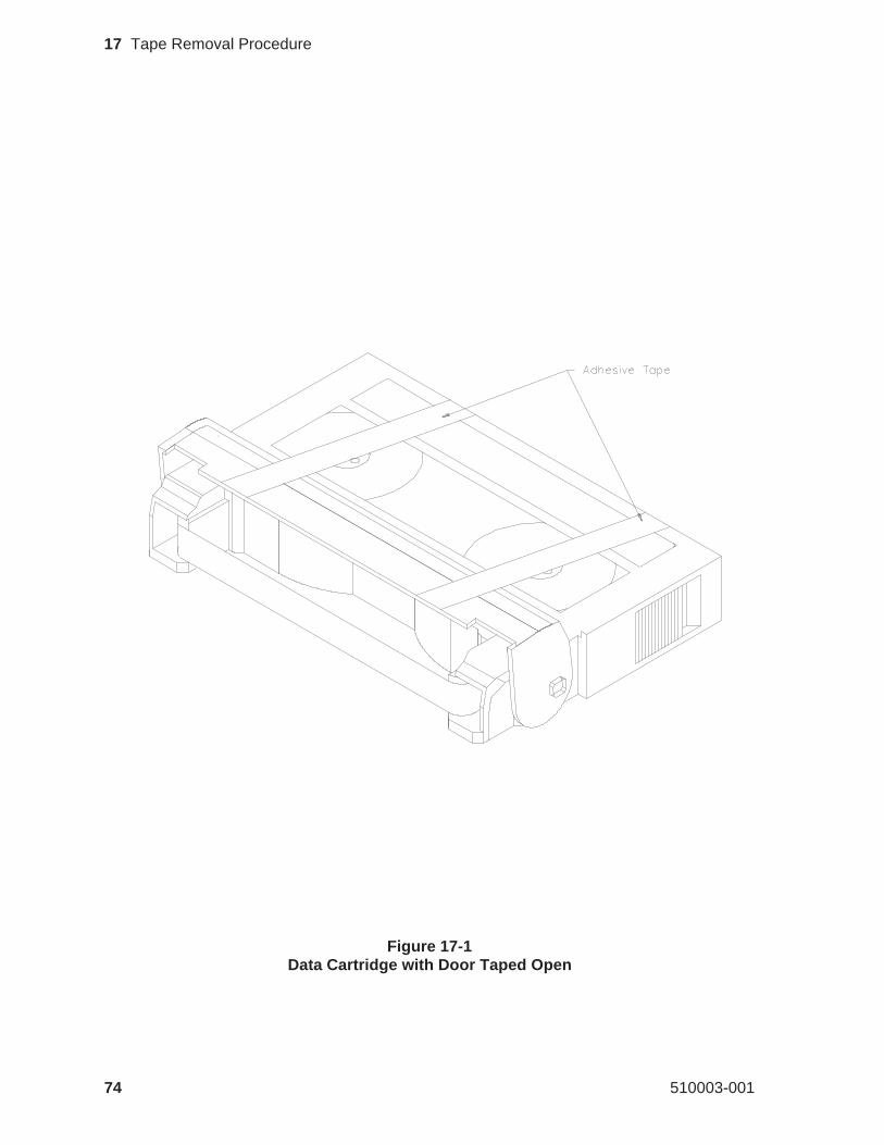
Figure 17-1Data Cartridge with Door Taped Open
74 510003-001
17 Tape Removal Procedure
17.3 Required Tools
The following tools are required:
3/8-inch straight blade screwdriverPointed tweezers#0 Phillips screwdriverT8 TORX screwdriverT10 TORX screwdriverTorque measuring screwdriver (1.0 to 5.0 inch-pounds)Adhesive tapeNonconductive tool, such as a molded potentiometer adjustment tool.
17.4 Disconnect the EXB-8200
Following all procedures appropriate to the system in which the EXB-8200 isinstalled, disconnect the EXB-8200 from the power supply and the SCSI bus.Remove the EXB-8200 from the system and transport it to the work area.
17.5 Preparation of the EXB-8200
Remove the top cover, as described in Section 4.
17.6 Cartridge Preparation
To prevent possible damage to the tape by the data cartridge door during thisprocedure, the door must be taped open. Taping the door open prevents thecartridge door from closing on the tape and damaging it before the tape is re-wound into the data cartridge. Figure 17-1 shows a data cartridge with thedoor taped open.
To tape the door open, follow these steps:
1. Obtain two pieces of adhesive tape, each approximately two inches long.
2. Position the two pieces of tape as shown in Figure 17-1, and press themgently to the data cartridge.
May 1990 75
17 Tape Removal Procedure
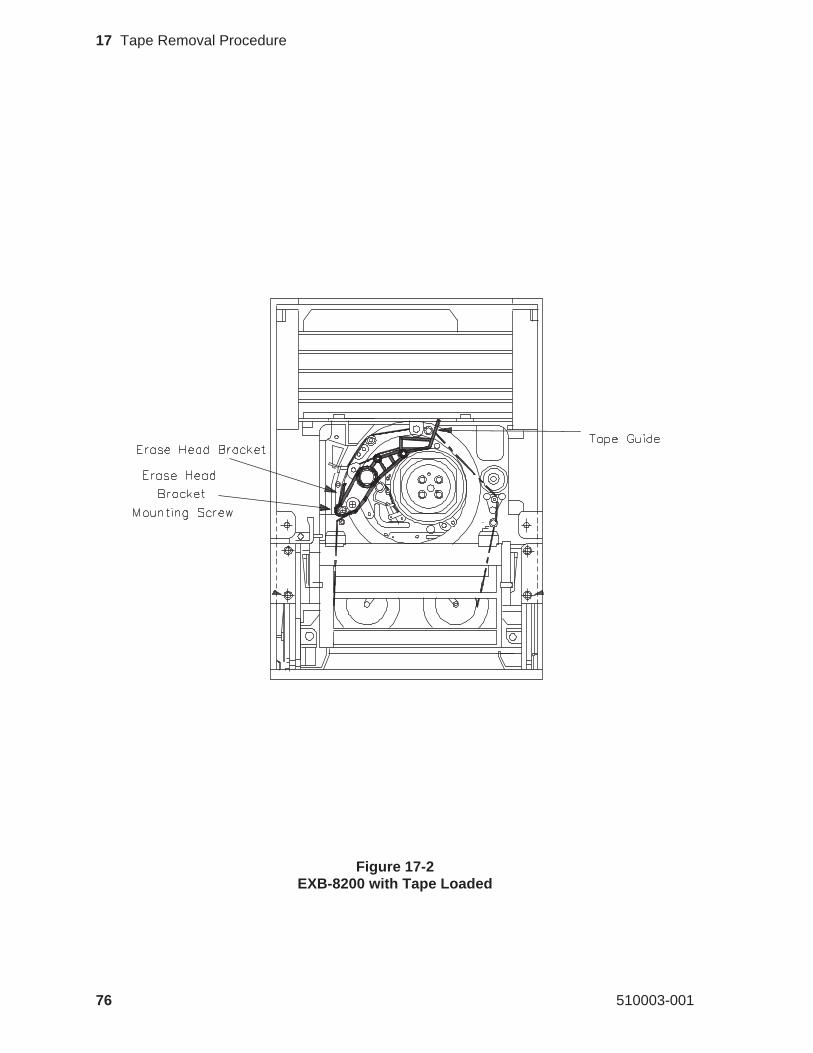
Figure 17-2EXB-8200 with Tape Loaded
76 510003-001
17 Tape Removal Procedure
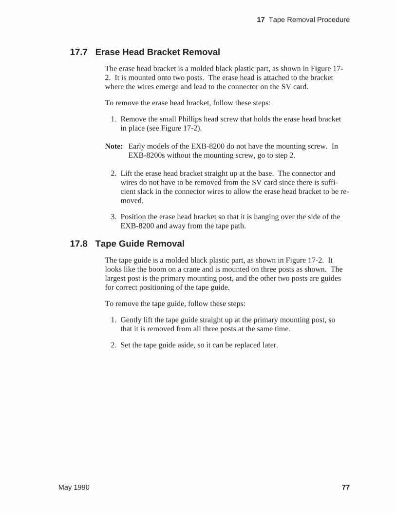
17.7 Erase Head Bracket Removal
The erase head bracket is a molded black plastic part, as shown in Figure 17-2. It is mounted onto two posts. The erase head is attached to the bracketwhere the wires emerge and lead to the connector on the SV card.
To remove the erase head bracket, follow these steps:
1. Remove the small Phillips head screw that holds the erase head bracketin place (see Figure 17-2).
Note: Early models of the EXB-8200 do not have the mounting screw. InEXB-8200s without the mounting screw, go to step 2.
2. Lift the erase head bracket straight up at the base. The connector andwires do not have to be removed from the SV card since there is suffi-cient slack in the connector wires to allow the erase head bracket to be re-moved.
3. Position the erase head bracket so that it is hanging over the side of theEXB-8200 and away from the tape path.
17.8 Tape Guide Removal
The tape guide is a molded black plastic part, as shown in Figure 17-2. Itlooks like the boom on a crane and is mounted on three posts as shown. Thelargest post is the primary mounting post, and the other two posts are guidesfor correct positioning of the tape guide.
To remove the tape guide, follow these steps:
1. Gently lift the tape guide straight up at the primary mounting post, sothat it is removed from all three posts at the same time.
2. Set the tape guide aside, so it can be replaced later.
May 1990 77
17 Tape Removal Procedure
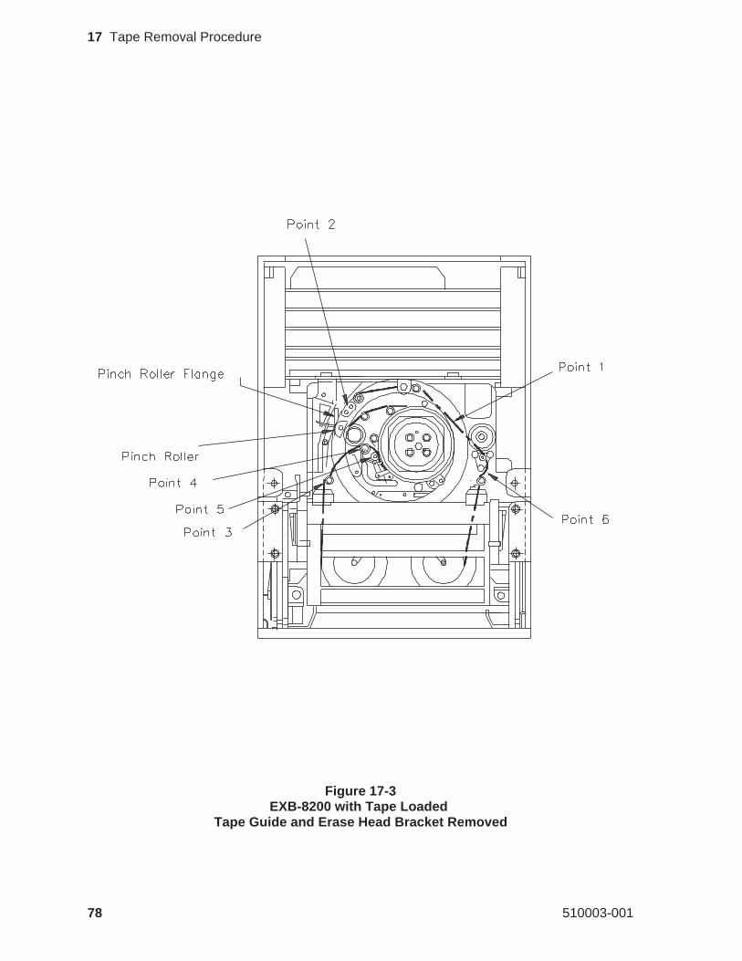
Figure 17-3EXB-8200 with Tape Loaded
Tape Guide and Erase Head Bracket Removed
78 510003-001
17 Tape Removal Procedure
17.9 Tape Removal
CAUTION
EXABYTE considers this procedure to have a high potential for dam-age to the media and the heads on the EXB-8200.Use extreme cau-tion when attempting to remove the tape using this procedure.
When removing the tape from the guide posts and rollers, use a nonconduc-tive tool, such as a molded potentiometer adjustment tool. Avoid touchingthe side of the tape where data is recorded. If you are unsure of which side ofthe tape to touch with the tool, carefully inspect the tape path before startingthis procedure. The side of the tape that comes in direct contact with the rotat-ing head assembly is the side where data is recorded. It is duller in color thanis the back of the tape.
To remove the tape, follow these steps:
1. Using the nonconductive tool, loosen the tape at point 1, shown in Figure17-3, by positioning the tool between the tape and the rotating head andmoving the tool toward the rear of the EXB-8200. This action pulls thetape off of the takeup reel and makes a loose loop in the tape.
2. Using your finger, move the pinch roller flange toward the left side ofthe EXB-8200 and hold it in this position. This will release the pinchroller from the capstan and provide a gap between the pinch roller andthe pinch roller flange.
3. Insert the tool in the tape loop at point 2 and gently lift the tape up fromaround the pinch roller and capstan.
CAUTION
After starting to remove the tape, do not release the pinch roller untilthe tape is completely removed from around the pinch roller and cap-stan. If the pinch roller is released before the tape is clear of thesecomponents, the tape will be damaged.
4. After the tape is completely clear of the pinch roller and the capstan, re-lease the pinch roller flange.
May 1990 79
17 Tape Removal Procedure
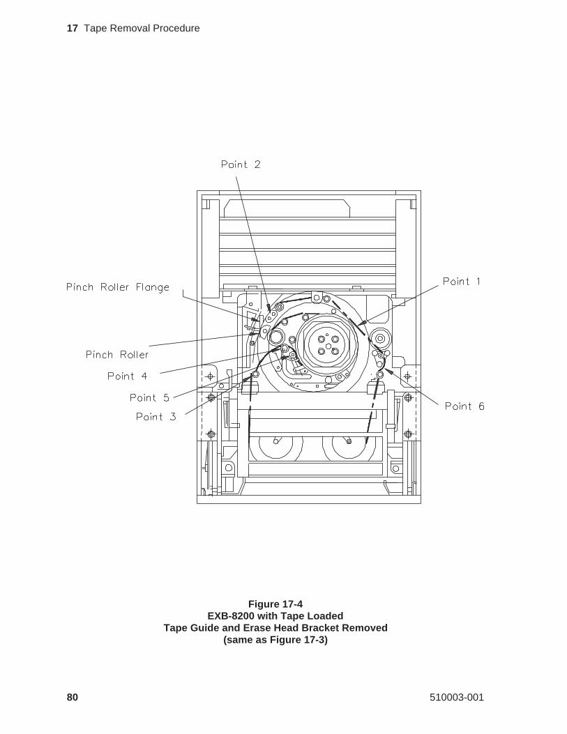
Figure 17-4EXB-8200 with Tape Loaded
Tape Guide and Erase Head Bracket Removed(same as Figure 17-3)
80 510003-001
17 Tape Removal Procedure
5. Remove the tape from around the guide posts and rollers at points 3 and4, shown in Figure 17-4. Be sure to place the tool inside the tape loop toavoid touching the tape recording surface or the rotating head assembly.
6. Position the tool between points 4 and 5 inside the tape loop. Point 5,shown in Figure 17-4, is an “L” shaped molded black plastic part. The“L” is mounted upside-down and prevents the tape from riding up overthe rotating drum. Gently move the tape up so that it passes between the“L” and the edge of the rotating head assembly.
Note: Be careful that the tape is not creased or damaged in any way when re-moving it from this point.
7. Lift the tape from around the guide posts and roller at point 6, shown inFigure 17-4. Be sure to place the tool inside the tape loop.
17.10 Remove Faceplate and Open Door
To remove the faceplate, refer to the instructions in Section 12. Be especiallycareful when removing the faceplate with a data cartridge in the EXB-8200.When opening the door as described in Section 13, hold the door so that thedoor opens more slowly than normal. This will prevent the data cartridgefrom being moved quickly and damaging the media.
17.11 Wind Loose Tape and Eject Data Cartridge
With the faceplate removed and the door open, you can rewind the tape. Towind the loose tape and eject the data cartridge, follow these steps:
1. Position the EXB-8200 so that it is resting on the left side of the mainhousing with the door facing to your left.
2. Insert the 3/8-inch straight blade screwdriver between the bottom edge ofthe door and the edge of the EXB-8200.
3. Insert the blade of the screwdriver into the hub of the takeup reel (the tophub with the EXB-8200 in the current position).
4. Slowly turn the screwdriver counterclockwise to wind any loose tapeonto the data cartridge.
Note: As you are rewinding the tape manually, you may hear a ratchetingsound. This sound is normal and does not indicate that the tape is be-ing damaged.
May 1990 81
17 Tape Removal Procedure
While turning the screwdriver, watch the tape loop to ensure that it doesnot get caught on any of the components. If the tape gets caught, free itand continue turning the screwdriver.
CAUTION
Make sure that all of the loose tape in the tape loop has been woundinto the data cartridge. If all of the tape is not wound in the data car-tridge, the tape will be damaged by the cartridge door. In addition,once the loose tape has been wound onto the takeup reel, do not over-wind the tape into the cartridge. Overwinding will damage the tape.
5. When all of the loose tape has been wound into the data cartridge, re-move the screwdriver.
6. Remove the adhesive tape that is holding the door of the data cartridgeopen.
7. Carefully close the door on the data cartridge, checking to ensure that thedoor does not contact the exposed tape. Then, remove the data cartridge.
8. Replace the tape guide. Ensure that it fits onto all three guide posts start-ing with the primary post.
9. Replace the erase head bracket. Replace the mounting screw if thebracket had one. Tighten the screw to 1.7 inch-pounds of torque.
17.12 Reassemble the EXB-8200
To reassemble the EXB-8200, replace these parts in the following order:
Faceplate Section 12Top cover Section 4
82 510003-001
17 Tape Removal Procedure
18 Head Sync Adjustment Procedure
This section describes how to adjust the head sync timing on an EXB-8200 toensure interchangeability of data. The head sync timing needs to be adjustedwhenever an SV card or a deck is replaced. The head sync adjustment proce-dure entails checking the head sync timing, adjusting it if necessary, and veri-fying the adjustment.
18.1 Requirements
Before you set the head sync timing, ensure that you have ready access to thefollowing tools, test equipment, software, and user’s manuals.
18.1.1 Tools
T8 TORX screwdriverT10 TORX screwdriverTorque measuring screwdriver (1.0 to 5.0 inch-pounds)TweezersStraight blade screwdriver - # 1Head sync tapeThreebond screwlocking agentLoctite X-NMS Cleanup SolventPotentiometer adjustment tool.
IMPORTANT
To ensure accurate results, replace the head sync tape after rewindingit 150 times. Continuing to use the tape after 150 rewinds may causethe head sync signal to become degraded, which can make adjustingthe head sync timing more difficult.
18.1.2 Test Equipment
IBM or compatible personal computer system with a color monitor and aserial port
Adaptec SDS-1 family or SDS-3 family SCSI controller or an AdvancedStorage Concepts ASC-88 SCSI controller installed in the computer sys-tem
SCSI bus cable properly connected to the Adaptec or ASC-88 controllerand properly terminated
May 1990 83
18 Head Sync Adjustment Procedure
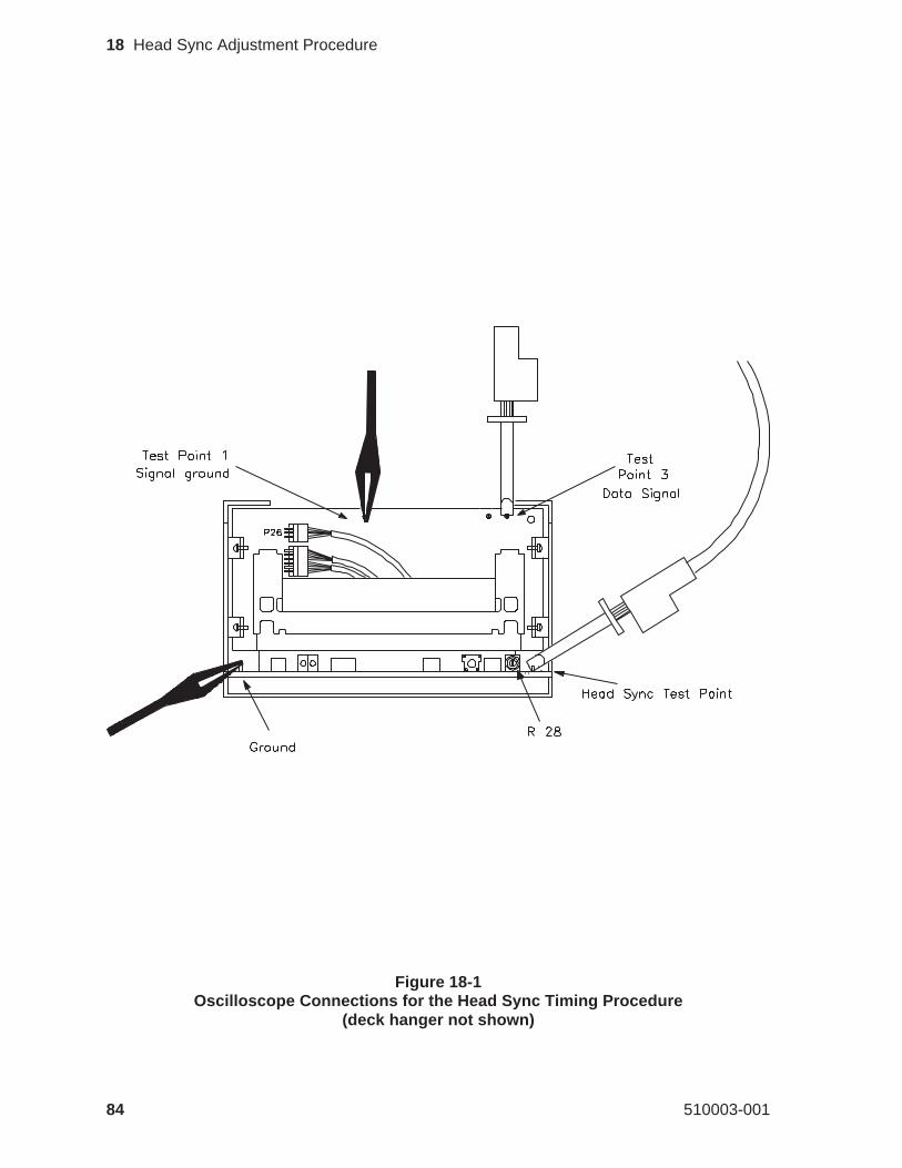
Figure 18-1Oscilloscope Connections for the Head Sync Timing Procedure
(deck hanger not shown)
84 510003-001
18 Head Sync Adjustment Procedure
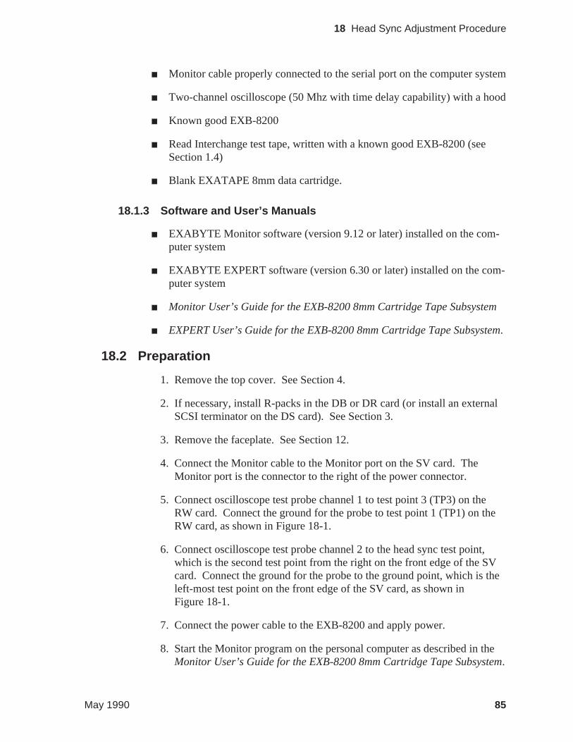
Monitor cable properly connected to the serial port on the computer system
Two-channel oscilloscope (50 Mhz with time delay capability) with a hood
Known good EXB-8200
Read Interchange test tape, written with a known good EXB-8200 (seeSection 1.4)
Blank EXATAPE 8mm data cartridge.
18.1.3 Software and User’s Manuals
EXABYTE Monitor software (version 9.12 or later) installed on the com-puter system
EXABYTE EXPERT software (version 6.30 or later) installed on the com-puter system
Monitor User’s Guide for the EXB-8200 8mm Cartridge Tape Subsystem
EXPERT User’s Guide for the EXB-8200 8mm Cartridge Tape Subsystem.
18.2 Preparation
1. Remove the top cover. See Section 4.
2. If necessary, install R-packs in the DB or DR card (or install an externalSCSI terminator on the DS card). See Section 3.
3. Remove the faceplate. See Section 12.
4. Connect the Monitor cable to the Monitor port on the SV card. TheMonitor port is the connector to the right of the power connector.
5. Connect oscilloscope test probe channel 1 to test point 3 (TP3) on theRW card. Connect the ground for the probe to test point 1 (TP1) on theRW card, as shown in Figure 18-1.
6. Connect oscilloscope test probe channel 2 to the head sync test point,which is the second test point from the right on the front edge of the SVcard. Connect the ground for the probe to the ground point, which is theleft-most test point on the front edge of the SV card, as shown inFigure 18-1.
7. Connect the power cable to the EXB-8200 and apply power.
8. Start the Monitor program on the personal computer as described in theMonitor User’s Guide for the EXB-8200 8mm Cartridge Tape Subsystem.
May 1990 85
18 Head Sync Adjustment Procedure
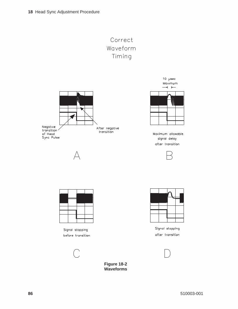
Figure 18-2Waveforms
86 510003-001
18 Head Sync Adjustment Procedure
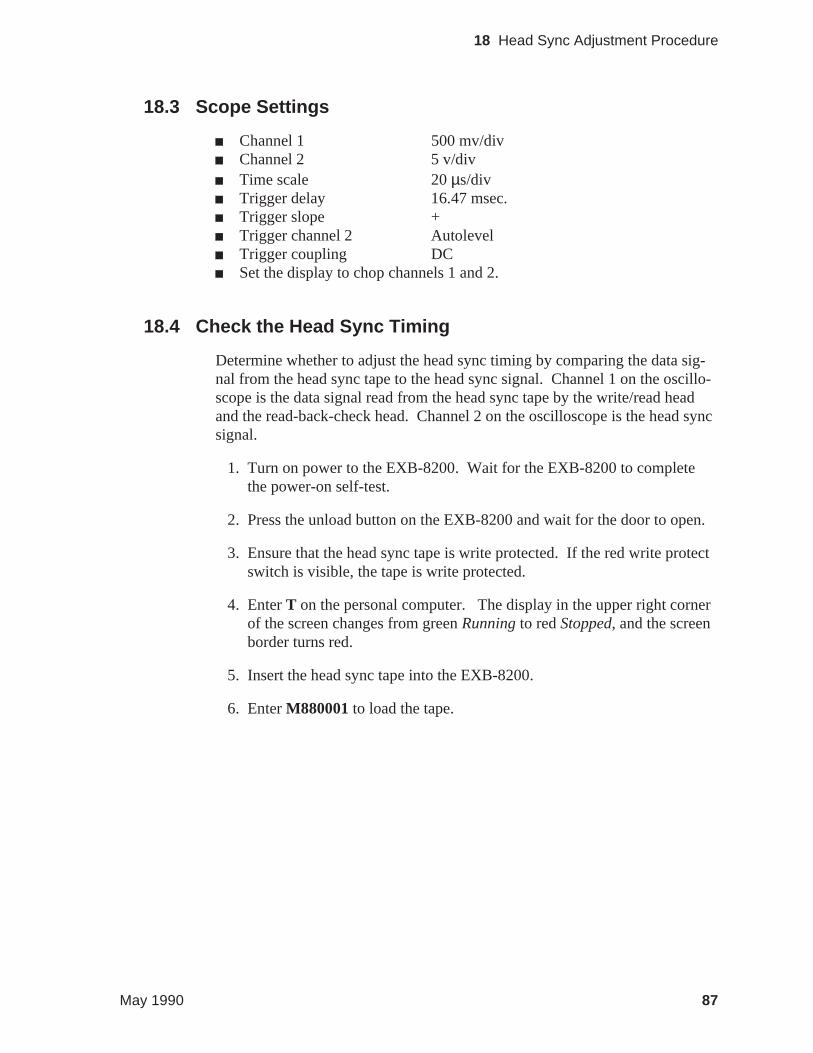
18.3 Scope Settings
Channel 1 500 mv/divChannel 2 5 v/divTime scale 20µs/divTrigger delay 16.47 msec.Trigger slope +Trigger channel 2 AutolevelTrigger coupling DCSet the display to chop channels 1 and 2.
18.4 Check the Head Sync Timing
Determine whether to adjust the head sync timing by comparing the data sig-nal from the head sync tape to the head sync signal. Channel 1 on the oscillo-scope is the data signal read from the head sync tape by the write/read headand the read-back-check head. Channel 2 on the oscilloscope is the head syncsignal.
1. Turn on power to the EXB-8200. Wait for the EXB-8200 to completethe power-on self-test.
2. Press the unload button on the EXB-8200 and wait for the door to open.
3. Ensure that the head sync tape is write protected. If the red write protectswitch is visible, the tape is write protected.
4. EnterT on the personal computer. The display in the upper right cornerof the screen changes from greenRunningto redStopped, and the screenborder turns red.
5. Insert the head sync tape into the EXB-8200.
6. EnterM880001to load the tape.
May 1990 87
18 Head Sync Adjustment Procedure
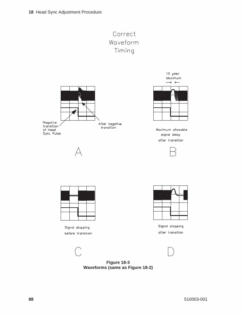
Figure 18-3Waveforms (same as Figure 18-2)
88 510003-001
18 Head Sync Adjustment Procedure
7. EnterM880004to move the tape forward.
Note: Other useful commands for controlling tape movement include:
M880001 Load tapeM880002 Unload and eject tapeM880003 Space forward to LBOTM880004 Go trackM880007 Rewind to physical beginning of tape (PBOT)M88000C Stop tape
8. Adjust the trigger delay on the oscilloscope so that the negative transi-tion of the head sync signal (channel 2) is centered on the oscilloscopescreen.
9. Wait at least 20 seconds before proceeding to the next step to allow thesignals to become stable.
10. Compare the data signal from the head sync tape (channel 1) to the headsync signal to determine whether you need to adjust the head sync tim-ing. Figure 18-3 shows correct and incorrect waveforms.
If the two data signals on channel 1 are within 10µsec. of meetingeach other after the negative transition point of the head sync signal,no adjustment is necessary. See Figure 18-3B.
If the two data signals approach each other before the negative transi-tion of the head sync signal, adjustment is necessary. SeeFigure 18-3C.
If the separation between the two signals is more than 10µsec., ad-justment is also necessary. See Figure 18-3D.
11. EnterM88000C to stop the tape.
12. If you need to adjust the head sync timing, go to Section 18.5.
or
If you do not need to adjust the head sync timing, enterM880002to un-load and eject the tape. Then, exit the Monitor program.
May 1990 89
18 Head Sync Adjustment Procedure
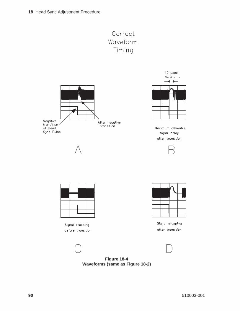
Figure 18-4Waveforms (same as Figure 18-2)
90 510003-001
18 Head Sync Adjustment Procedure
18.5 Adjust the Head Sync Timing
The head sync adjustment potentiometer is labeled R28 on the SV card. It isjust to the left of the head sync test point on the front edge of the SV card.
To adjust the head sync timing, follow these steps:
1. Carefully remove the Threebond screwlocking agent from the head syncadjustment potentiometer. Hold the potentiometer with one finger whileremoving the Threebond with a sharp instrument such as a pair of tweez-ers. If this method does not remove enough of the Threebond to adjustthe potentiometer, use Loctite X-NMS Cleanup Solvent to dissolve theThreebond. Be careful not to break the potentiometer by forcing it whilethere is still Threebond holding it secure.
2. EnterM880004to move the tape forward
3. Using a straight blade screwdriver or potentiometer adjustment tool, turnthe head sync adjustment potentiometer clockwise until the data signalstops at the negative-going transition of the head sync signal, becomes astraight line, and starts up again to the right of the transition point. SeeFigure 18-4D.
4. Turn the head sync adjustment potentiometer counterclockwise until thedata signals meet. See Figure 18-4A.
Note: If the data signal is unstable and varies in amplitude making this proce-dure difficult to perform, follow these steps:
a. EnterM88000Cto stop the tape motion.b. EnterM880007to rewind the tape to PBOT.c. EnterM880003to advance the tape to LBOT.d. Restart the head sync adjustment from step 2.
5. EnterM88000C to stop tape movement.
6. EnterM880002to unload and eject the tape.
May 1990 91
18 Head Sync Adjustment Procedure
18.6 Verify the Adjustment
After adjusting the head sync timing, verify that it is adjusted correctly. Toverify the adjustment, follow these steps:
1. Connect the SCSI cable to the personal computer and to the EXB-8200.
2. Start EXPERT software on the personal computer (refer to theEXPERTUser’s Guide).
3. Load the Read Interchange tape that was written on a known goodEXB 8200.
4. Perform a read only Inter_chg test.
If the EXB-8200 fails this test, reset the head sync timing. If theEXB-8200 passes this test, go to step 5.
5. Unload the tape and insert a blank EXATAPE.
6. Perform a write Inter_chg test.
7. Unload the tape, insert it into the known good EXB-8200, and perform aread only Inter_chg test.
8. If the EXB-8200 passes both of the Inter_chg tests, the head sync timingadjustment is complete. Apply one drop of Threebond to the head syncpotentiometer to secure the adjustment.
or
If the EXB-8200 fails either of the Inter_chg tests, recheck the head synctiming and, if necessary, reset the head sync timing.
Note: If the head sync timing is adjusted correctly and the EXB-8200 failsthe Inter_chg tests, look for other causes for the failure.
18.7 Reassemble the EXB-8200
To reassemble the EXB-8200, replace these parts in the following order:
Faceplate Section 12Top cover Section 4
92 510003-001
18 Head Sync Adjustment Procedure
B
bezelSeefaceplate
bottomSeeSV card cover
C
card retainersremoving 25replacing 25
cardshandling 31, 35, 51MX card EPROM removal and replacement 43 - 49removing and replacing edge mounted 29 - 33RW card connectors 33SV card EPROM removal and replacement 51 - 55SV card removal and replacement 35 - 41
CD card removal and replacement 29 - 33chassis
Seemain housingcleaning cartridge 71cleaning procedure
accepted products for 71instructions for 72intervals for 71minimum firmware for 71
coverSeeSV card coverSeetop cover
D
DB/DS/DR cards removal and replacement 29 - 33deck assembly
removing 65replacing 67
deck hangerremoving 27replacing 27
DF card removal and replacement 29 - 33DIP mounted R-packs
installing 15removing 15
dooropening manually 61removing 61replacing 63
E
edge connector mounted cardsremoving 31
replacing 33electrostatic discharge requirements 2environment
Seetest and repair environmentEPROM
removing and replacing on MX card 43 - 49removing and replacing on SV card 51 - 55versions of for MX card 43
erase head bracketremoving 77
EXB-8200adding in test and repair environment 9 - 13cleaning 71 - 72removing from test and repair environment 13removing tapes from 73 - 82tapes for testing 4testing 6tools and test equipment for 5
EXPERTusing to test EXB-8200 6using to test head sync adjustment 92
F
faceplateremoving 57replacing 59
firewallSeedeck hanger
frameSeemain housing
front bezelSeefaceplate
H
hangerSeedeck hanger
head sync timingadjusting 91checking adjustment of 87equipment for adjusting 83oscilloscope settings for 87procedure for adjusting 83 - 92verifying adjustment of 92
housingremoving 69replacing 70
M
main housingremoving 69replacing 70
Index
May 1990 93
Monitorcommands for moving tape 89
MS cardSeeMX card
MV cardSeeMX card
MX cardcompatibility of 29EPROM versions for 43removing and replacing 29 - 33removing and replacing EPROM on 43 - 49
O
oscilloscope settings for head sync adjustment 87
P
power supplyfor multiple drive configuration 9
R
R-packconfigurations of 15DIP mounted 15SIP mounted 17
Read Interchange test tape 4resistor terminators
SeeR-packRW card
connections on 33removing and replacing 29 - 33
S
SCSI addresssetting 9
SIP mounted R-packsinstalling 17removing 17
software required 6static protection requirements 2supplies
for cleaning EXB-8200 71required 6
SV cardremoving and replacing 35 - 41removing and replacing EPROM on 51 - 55
SV card coverremoving 23replacing 23
T
tape guideremoving 77
tapesfor testing EXB-8200 4removing from EXB-8200 manually 73 - 82
terminatorsSeeR-pack
test and repair environmentadding EXB-8200 to 9 - 13general requirements for 3removing EXB-8200 from 13requirements for electrostatic discharge 2single power supply 9
test equipment required 5test tapes 4testing
EXB-8200 6tools required 5top cover
removing 19replacing 21
W
Write Interchange test tape 4
94 510003-001
Index