Mitsubishi Molded-case Circuit Breakers and Earth-leakage Circuit Breakers
Molded-case Circuit BreakersEarth-leakage Circuit Breakers

INDEX This document is intended for those having electrical knowledge
and expertise, such as those using these products for manufacturing
assemblies, carrying out electrical installation, maintenance and
inspection, including the operators (end users) of these products.
Introduction 1 – 12................................................................................................................................
Molded-case Circuit Breakers Earth-leakage Circuit BreakersMotor-protection Breakers
..............................................................................................................................................................................................................................................................................
..............................................................................................................................................
132125
1. Detailed Specifications 13.................................................................................................................
2. Special-purpose Breakers 27............................................................................................................
Mag Only (Instantaneous tripping circuit breakers)DC MCCBs and DSN Switches400Hz MCCBsLow-instantaneous MCCBsGenerator Protection MCCBsMeasuring Display Unit (MDU)
....................................................................................................................................................................................................................................................
................................................................................................................................................................................................................................................................................................................
.................................................................................................................................................................................................................................................................................
272728282829
3. Connection Method 32......................................................................................................................
1

NoteThis document describes the product specifications for selecting an appropriate low-voltage circuit breaker. A separate document “Handling and Maintenance” describing the operating instructions in detail. Please be sure to request a copy for using the selected product correctly.
Internal Accessories1. Accessories2. Switch Operation and Rating3. Maximum Number of Internally Mounted Accessories4. Shunt Trip (SHT)5. Undervoltage Trip (UVT)6. Test Button Module (TBM)7. Lead-wire Specifications8. Vertical Lead-wire Terminal Block (SLT)9. Cassette-type Accessories
10. Pre-alarm Module (PAL)External Accessories
1. F-type Operating Handle2. V-type Operating Handle3. S-type Operating Handle4. Terminal Cover5. Electrical Operation Device6. Mechanical Interlocks (MI)7. Handle Lock Devices and Card Holder8. IEC 35mm Rail Mounting Adapters9. Insulating Barrier
......................................................................................................................................................................................................................................................................................................................................
...............................................................................................................................................................................................................................................................
................................................................................................................................................................................................................................................................................................................................
.................................................................................................................................................................................................................................................................................................................
........................................................................................................................................................................................................................................................................................
..................................................................................................................................................................................................................................................................................................................
.........................................................................................................................................................
.........................................................................................................................................................
.................................................................................................................................................................................................................................................................................................................................
...........................................................................................................................................................................................................................................................................................................
............................................................................................................................................................................................................................................................................
.....................................................................................................................................................................
333333343535353535363637373839394040414141
Molded-case Circuit BreakersEarth-leakage Circuit BreakersMotor-protection Breakers
..............................................................................................................................................................................................................................................................................
..............................................................................................................................................
435563
4. Accessories 33...................................................................................................................................
5. Characteristics and Dimensions 43..................................................................................................
(http://www.MitsubishiElectric.co.jp/haisei/lvs/)
6. LOW-VOLTAGE SWITCHGEAR TECHNICAL INFORMATION SERVICE VIA THE INTERNET 67.......
2

3

4
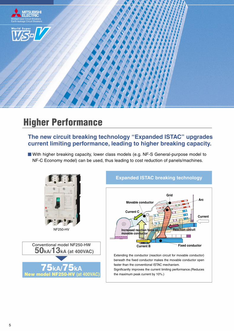
Arc
Fixed conductor
Movable conductor
Grid
Reaction circuitReaction circuitIncreased reaction force of movable conductorIncreased reaction force of movable conductor
Current CCurrent
Current B
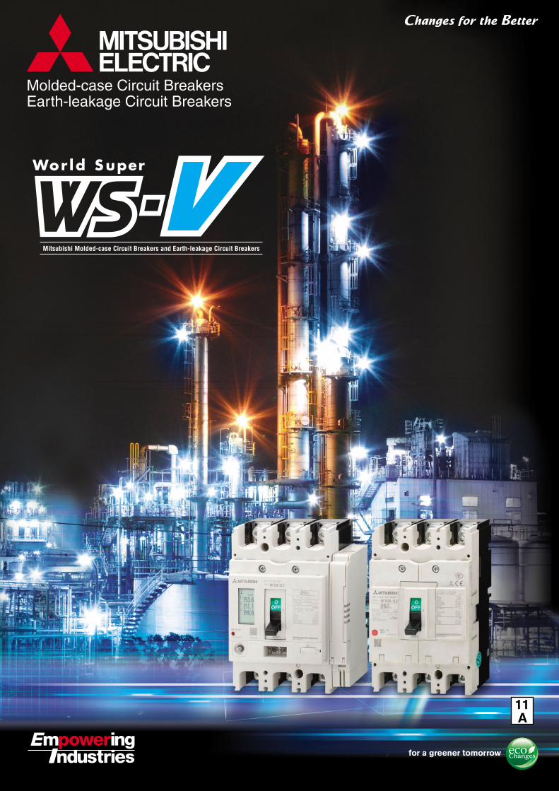
NF250-HV
The new circuit breaking technology “Expanded ISTAC” upgrades current limiting performance, leading to higher breaking capacity.
Higher Performance
Expanded ISTAC breaking technology
With higher breaking capacity, lower class models (e.g. NF-S General-purpose model to NF-C Economy model) can be used, thus leading to cost reduction of panels/machines.
Conventional model NF250-HW
50kA/13kA (at 400VAC)
New model NF250-HV (at 400VAC)75kA/75kA
Extending the conductor (reaction circuit for movable conductor)
beneath the fixed conductor makes the movable conductor open
faster than the conventional ISTAC mechanism.
Significantly improves the current limiting performance.(Reduces
the maximum peak current by 10%.)
Molded-case Circuit BreakersEarth-leakage Circuit Breakers
5

VisualizationThe new electronic circuit breakers (with display) and MDU breakers can display various measurement items. This will enable energy management through “visualization”, which leads to energy saving.
Electronic circuit breaker (with display)
MDU breakers
The display is on the circuit breaker body and shows circuit information.
Detailed setting can be done on the display.
The display turns red during alarms.
Current in each phase AlarmDisplay
6

(Conventional model : 105 × 165 × 86mm)
Volume ratio 74%(Compared with our conventional models)
(New model : 105 × 165 × 68mm)
The thermal adjustable circuit breakers and electronic circuit breakers are smaller.
Compact
These breakers contribute to the reduction of panel size.
250AF circuit breakers’ fixed types (NF250-CV, NF250-SV, NF250-HV, NV250-CV, NV250-SV, NV250-HV), thermal adjustable types (NF250-SGV, NF250-HGV, NF250-RGV), and electronic types (NF250-SEV, NF250-HEV, NV250-SEV, NV250-HEV) are the same size, leading to the standardization of panel design.
NF250-SGW NF250-SGV
Molded-case Circuit BreakersEarth-leakage Circuit Breakers
7

Conventional models
New models
Three types
One type For 32 to 250AF
For 32/63AF
For 125AF
For 250AF
Applicable accessories
StandardizationTypes of internal accessories are reduced from 3 types to 1 type.
AL AX AL+AX SHT UVT
Standardization of internal accessories contributes to the reduction of stock and delivery time.
32AF and 63AF circuit breakers can now be used in both AC and DC circuits without specifying when ordering. This will lead to prevention of ordering mistakes.
The earth-leakage circuit breakers can now be equipped with a voltage shunt trip device (SHT).
8
Eco-friendly design is used for all circuit breakers, and they do not use hazardous substances.The circuit
breakers comply with RoHS regulation.
Nonuse of Hazardous Substances
The circuit breakers are made of thermo-plastic materials that are easy to recycle.
(Some models are partially made of thermoset materials.)
The major plastic parts bear material identifications so that
they can be recycled.
Use of Various Recyclable Materials
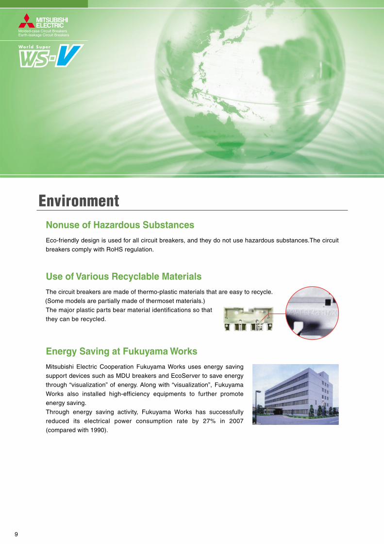
Mitsubishi Electric Cooperation Fukuyama Works uses energy saving
support devices such as MDU breakers and EcoServer to save energy
through “visualization” of energy. Along with “visualization”, Fukuyama
Works also installed high-efficiency equipments to further promote
energy saving.
Through energy saving activity, Fukuyama Works has successfully
reduced its electrical power consumption rate by 27% in 2007
(compared with 1990).
Energy Saving at Fukuyama Works
Environment
Molded-case Circuit BreakersEarth-leakage Circuit Breakers
9

New models
NF-C economytype
NF-S standardtype
NF-H high-performancetype
NF-U ultra current-limitingtype
Molded-case circuit breakers
NV-C economytype
NV-S standardtype
NV-H high-performancetype
Earth-leakage circuit breakers
Earth-leakage Circuit Breakers
Motor Protection
MDU Breakers
Product Line-up
Motor circuit breaker
Motor protection
MDU breakersNF-S, NF-H
types
30 32
NF-C economy type
NF-S standard type
NF-H high-performance type
NF-U ultra current-limiting type
100 125 160 225 250 400
NF32-SV NF63-SV
NF63-CV
NF63-HV
NF125-SV
NF125-CV
NF125-SGVNF125-SEV
NF125-HVNF125-LGVNF125-HGVNF125-HEV
NF125-RGV
NF125-UGV
NF160-SGV
NF160-LGVNF160-HGV
NF250-SV
NF250-CV
NF250-SGVNF250-SEV
NF250-HVNF250-LGVNF250-HGVNF250-HEV
NF250-RGV
NF250-UGV
NF400-SW
NF400-CW
NF400-SEW
NF400-HEW
NF400-REW
NF400-UEW
NF630-SW
NF630-CW
NF630-SEW
NF630-HEW
NF400-REW
NF800-SDW
NF800-CEW
NF800-SEW
NF800-HEW
NF800-REW
NF800-UEW
NF1000-SEW NF1250-SEW NF1600-SEW
600 630 800 1000 1250 160050 60 63Frame(A)Types
30 32
NV-C economy type
NV-S standard type
NV-H high-performance type
100 125 160 225 250 400
NV32-SV NV63-SV
NV63-HV
NV63-CV
NV125-SV
NV125-SEV
NV125-HVNV125-HEV
NV125-CV
NV250-SV
NV250-SEV
NV250-HVNV250-HEV
NV250-CV
NV400-SW
NV400-SEW
NV400-HEW
NV400-CW
NV630-SW
NV630-CW
NV600-HEW
NV800-SEW
NV800-HEW
600 630 80050 60 63Frame(A)Types
30 32
Motor circuit breaker
100 125 160 225 250 400
NF32-SV
NF63-CV
NF63-SVNF125-SV NF250-SV
600 630 80050 60 63Frame(A)Types
30 32 100 125 160 225 250 400NF250-SEVNF250-HEV
NF400-SEPNF400-HEP
NF600-SEPNF600-HEP
NF800-SEPNF800-HEP
600 630 80050 60 63Frame(A)Types
NF-S, NF-H types
Molded-case Circuit Breakers
10

11
Molded-case Circuit Breakers Earth-leakage Circuit Breakers
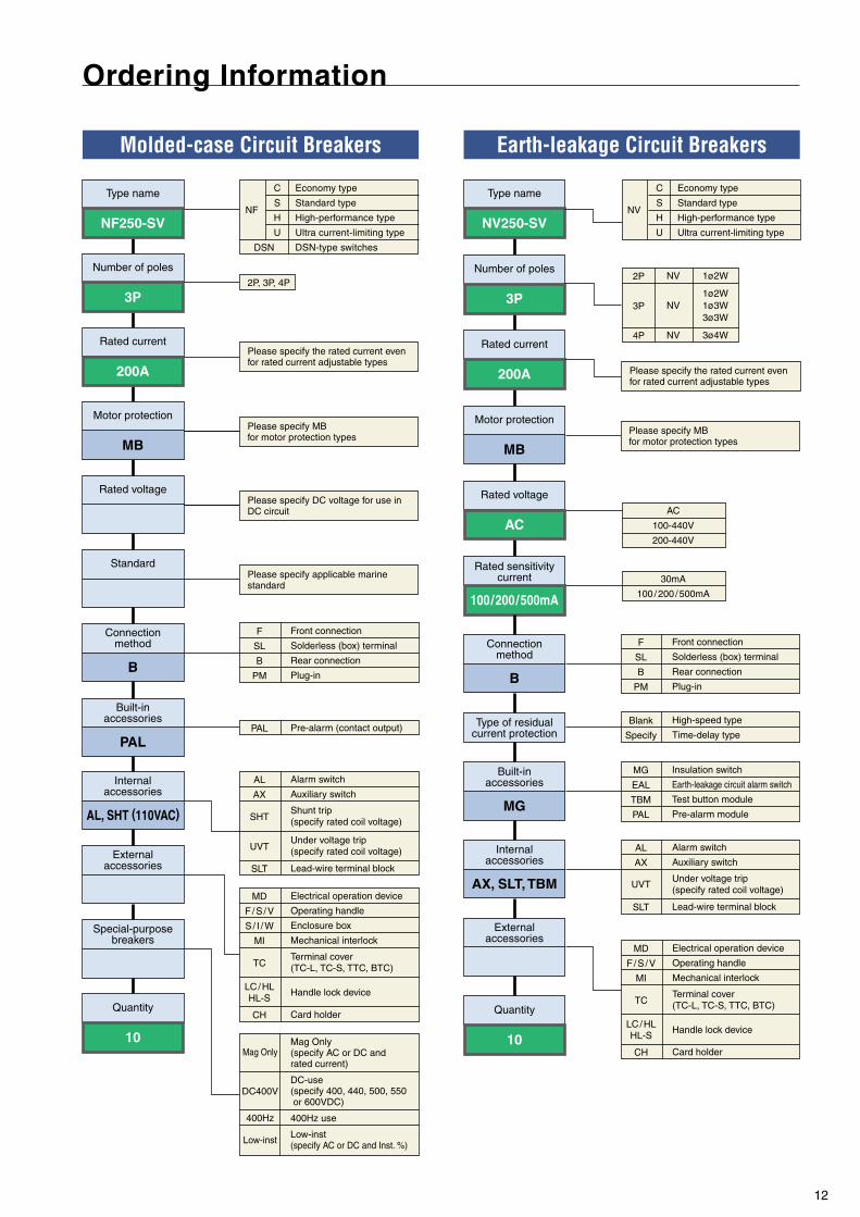
NF250-SV
3P
200A
10 10
NV250-SV
3P
200A
AC
100 / 200 / 500mA
Type name
Number of poles
Rated current
Special-purposebreakers
B
MB
Rated voltage
Standard
Connectionmethod
B
Connectionmethod
Motor protection
AL, SHT (110VAC)
Internalaccessories
Externalaccessories
Quantity Quantity
AX, SLT, TBM
Internalaccessories
Externalaccessories
Type name
Number of poles
Rated current
Rated voltage
Rated sensitivitycurrent
Type of residualcurrent protection
C
S
H
U
Economy type
Standard type
High-performance type
Ultra current-limiting type
DSN-type switches
NF
DSN
C
S
H
U
Economy type
Standard type
High-performance type
Ultra current-limiting type
NV
NV
NV
NV
1ø2W
1ø2W1ø3W3ø3W
3ø4W
2P
3P
4P
Front connection
Solderless (box) terminal
Rear connection
Plug-in
F
SL
B
PM
PAL
Built-inaccessories
Pre-alarm (contact output)PALHigh-speed type
Time-delay type
Blank
Specify
Alarm switch
Auxiliary switch
Shunt trip(specify rated coil voltage)
Under voltage trip(specify rated coil voltage)
Lead-wire terminal block
AL
AX
SHT
UVT
SLT
Electrical operation device
Operating handle
Enclosure box
Mechanical interlock
Terminal cover(TC-L, TC-S, TTC, BTC)
Handle lock device
Card holder
MD
F / S / V
S / I / W
MI
TC
LC / HLHL-S
CH
Mag Only(specify AC or DC and rated current)
DC-use(specify 400, 440, 500, 550 or 600VDC)
400Hz use
Low-inst(specify AC or DC and Inst. %)
Mag Only
DC400V
400Hz
Low-inst
Please specify applicable marine standard
Please specify DC voltage for use in DC circuit
Please specify the rated current even for rated current adjustable types
Please specify the rated current even for rated current adjustable types
AC
100-440V
200-440V
30mA
100 / 200 / 500mA
Alarm switch
Auxiliary switch
Under voltage trip(specify rated coil voltage)
Lead-wire terminal block
AL
AX
UVT
SLT
Electrical operation device
Operating handle
Mechanical interlock
Terminal cover(TC-L, TC-S, TTC, BTC)
Handle lock device
Card holder
MD
F / S / V
MI
TC
LC / HLHL-S
CH
Front connection
Solderless (box) terminal
Rear connection
Plug-in
F
SL
B
PM
MG
Built-inaccessories
Insulation switch
Earth-leakage circuit alarm switch
Test button module
Pre-alarm module
MG
EAL
TBM
PAL
Ordering Information
2P, 3P, 4P
Motor protectionPlease specify MBfor motor protection types
Please specify MBfor motor protection types
MB
12

13
Notes: *1 The trip action characteristics differ between AC and DC for products that are compatible with both AC and DC.
*2 Use two poles for three- and four-pole products. If wired as shown on the right, three and four poles can be used for up to
400 and 500VDC, respectively.
*3 The cassette-type design makes it easy for customer to install. Available for installation on side (excluding UVT).
*4 Not isolation-compatible.
*5 Use two poles for three- and four-pole products. In this case, do not use the neutral pole of the four-pole products. Not
available for use with connection as shown on the right.
*6 Use two poles for three- and four-pole products. If wired as shown on the right, three and four poles can be used for up to
500 and 600VDC, respectively.
Line
3-poleLoad
Line
4-poleLoad
Rated current In (A)
Number of polesRated ambient temperature (°C)Rated insulation voltage Ui (V)
Rated impulse withstand voltage Uimp (kV)
Suitability for isolationReverse connection
Current (*1)
Number of operating cyclesUtilization category
IEC 60947-2(Icu/Ics)
Ratedshort-circuitbreakingcapacities (kA)
690V500V440V415V400V380V230V250V
abcca
Enclosure
Electrical operation device
ClosedDustproofWaterproof
(S)(I)
(W)
Mechanical interlock (MI) (*4) Panel mounting
Handle lock deviceLCHLHL-S
External operating handle
(F)(V)(S) (*4)
Without currentWith current (440VAC)
AC
DC
Image
Frame (A)Type name
Terminal cover
Trip button
CE markingCCC recognitionAutomatic tripping device
IEC 35mm rail mounting adapters
(TC-L, TC-S, TTC, BTC, PTC)(B-ST)
(PM)
(NFM)
(F)(SL)(B)
(PM)(AL)(AX)
(SHT)(UVT)(SLT)(PAL)
FrontSolderless (BOX) terminalRearPlug-inAlarm switchAuxiliary switchShunt tripUndervoltage tripWith lead-wire terminal blockPre-alarm
a
b
cac
40 40 402 3 3
Pollution degree
Overall dimensions (mm)
Mass of front-face type (kg)
Installation and connections
Cassette-type accessories
External accessories
Rear studPlug-in
EMC environment condition (environment A or B)
63NF63-CV
3 4 (5) 6 10 (15) 16 2025 (30) 32 40 50 (60) 63
600–
2.5/2.52.5/2.52.5/2.5
5/55/5
7.5/7.52.5/2.5 (*5)
8AC/DC compatible
CompatiblePossible10,0006,000
A3
N/A
1306890
● (*3)● (*3)● (*3)● (*3)
●–
●
●
50 75 90
0.5 0.7
– ● ●
Self-declarationRecognized
Thermal-magneticEquipped
●–●
●
–●
●
●
●
●
●
●
●
●
●
●
2
125NF125-CV
50 (60) 63 (75) 80 100 125
600–
7.5/410/510/510/510/5
30/157.5/4 (*2)
8AC/DC compatible
CompatiblePossible10,0006,000
A3
N/A
1306890
● (*3)● (*3)● (*3)● (*3)
●–
●
●
60
0.6 1.0
–●–
Self-declarationRecognized
Thermal-magneticEquipped
●
●
●
●
●
●
●
●
●
●
●
●
●
●–
3
●
2
250NF250-CV
(100) 125 150 175200 225 250
600–
10/815/1225/1925/1925/1936/27
15/12 (*2)8
AC/DC compatibleCompatible
Possible8,0004,000
A3
N/A1051656892
● (*3)● (*3)● (*3)● (*3)
●–
●
●
1.3 1.5
–
TÜV approvalRecognized
Thermal-magneticEquipped
●
●
●
●
●
●
●
●
●
●
●
●
●
●
●–
1. Detailed SpecificationsMolded-case Circuit Breakers
NF-C (Economy type)

14
Remarks: 1. Products with rated current parenthesized are produced when an order is placed.
2. Specify “P-LT” when using a plug-in product with a lead-wire terminal block.
3. The circuit breaker has the rated short-circuit breaking capacity specified in the shaded cells.
2 3 4
50 75 100
– ● –
● (*3)● (*3)● (*3)● (*3)
●
●
●
●
●
●
––
––
●
●
– ●
–
●
●
––
● –
0.55 0.75 1.0
3
●
2
32NF32-SV
3 4 (5) 6 10 (15)16 20 25 (30) 32
600–
2.5/2.52.5/2.52.5/2.5
5/55/5
7.5/7.52.5/2.5 (*5)
8AC/DC compatible
CompatiblePossible10,0006,000
A3
N/A
40
1306890
● (*3)● (*3)● (*3)● (*3)
●–
●
●
0.45 0.65
50 75
–
Self-declarationRecognized
Thermal-magneticEquipped
●–●
●
–●
●
●
●
●
●
●
●
●
●
●
125NF125-SV
(15) 16 20 (30) 32 40 50(60) 63 (75) 80 100 125
6908/8
18/1825/2530/3030/3030/3050/50
40/40 (*2)8
AC/DC compatibleCompatible
Possible25,00010,000
A3
N/A
40
1306890
Self-declarationRecognized
Thermal-magneticEquipped
●
●
●
●
●
●
●
●
●
●
●
●
●–
60 90 120
0.7 0.95 1.3
2 3 4
63NF63-SV
3 4 (5) 6 10 (15) 16 20 25(30) 32 40 50 (60) 63
600–
7.5/7.57.5/7.57.5/7.57.5/7.57.5/7.515/15
7.5/7.5 (*5)8
AC/DC compatibleCompatible
Possible15,0008,000
A3
N/A
40
1306890
Self-declarationRecognized
Thermal-magneticEquipped
●–●
●
●–
● (*3)● (*3)● (*3)● (*3)
●
●
●
●
●–
–
●
●
●
––
125NF125-SGV
16-20 20-25 25-32 32-40 35-5045-63 56-80 70-100 90-125
6908/8
30/3036/3636/3636/3636/3685/85
20/20 (300V) (*6)8
AC/DC compatibleCompatible
Possible50,00030,000
A3
N/A
40
1656892
Self-declarationRecognition in process
Thermal-magneticEquipped
●
●
●
●
●
●
●
●
●
●
●
●
●
●
●–
105 140
1.4 1.6 2.0
2 3 4
● (*3)● (*3)● (*3)● (*3)
●
●
●
●
●–
–●
●
●
●
●
●
●
●
●
●
NF-S (Standard type)

15
Notes: *1 The trip action characteristics differ between AC and DC for products that are compatible with both AC and DC.
*2 Use two poles for three- and four-pole products. If wired as shown on the right, three and four poles can be used for up to
500 and 600VDC, respectively.
*3 The cassette-type design makes it easy for customer to install. Available for installation on side (excluding UVT).
*4 Not isolation-compatible.
Line
3-poleLoad
Line
4-poleLoad
125NF125-SEV
16-32 32-63 63-125 125-160
6908/8
30/3036/3636/3636/3636/3685/85
–8
ACCompatible
Possible25,00010,000
A3A
40
1656892
●
●
● (*3)● (*3)● (*3)● (*3)
●
●
●
●
3 4
105 140
1.7 2.2
●
●
●
–––
Self-declarationRecognized
Electronic (effective value detection)Equipped
●
●
●
●
160NF160-SGV
●
●
●
●
●
●
●
●
●
●
●–
250NF250-SV
(100) 125 150 160 175200 225 250
6908/8
30/3036/3636/3636/3636/3685/85
20/20 (300V) (*2)8
AC/DC compatibleCompatible
Possible25,00010,000
A3
N/A
1656892
●
●
●
–––
RecognizedThermal-magnetic
Equipped
●
●
●
●
●
●
●
●
●
●
●
●
●
●
●–
–
●
●
●
––
6908/8
30/3036/3636/3636/3636/3685/85
20/20 (300V) (*2)8
AC/DC compatibleCompatible
Possible40,00020,000
A3
N/A
4040
1656892
Self-declarationRecognition in process
Thermal-magneticEquipped
●
●
●
●
●
●
●
●
●
●
●
●
●
●
●–
105 140
1.4 1.6 2.0
2 3 4
● (*3)● (*3)● (*3)● (*3)
●
●
●
●
●–
2 3 4
105 140
● (*3)● (*3)● (*3)● (*3)
●
●
●
●
●–
TÜV approval Self-declaration
1.4 1.6 2.0
Rated current In (A)
Number of polesRated ambient temperature (°C)Rated insulation voltage Ui (V)
Rated impulse withstand voltage Uimp (kV)
Suitability for isolationReverse connection
Current (*1)
Number of operating cyclesUtilization category
IEC 60947-2(Icu/Ics)
Ratedshort-circuitbreakingcapacities (kA)
690V500V440V415V400V380V230V250V
abcca
Enclosure
Electrical operation device
ClosedDustproofWaterproof
(S)(I)
(W)
Mechanical interlock (MI) (*4) Panel mounting
Handle lock deviceLCHLHL-S
External operating handle
(F)(V)(S) (*4)
Without currentWith current (440VAC)
AC
DC
Image
Frame (A)Type name
Terminal cover
Trip button
CE markingCCC recognitionAutomatic tripping device
IEC 35mm rail mounting adapters
(TC-L, TC-S, TTC, BTC, PTC)(B-ST)
(PM)
(NFM)
(F)(SL)(B)
(PM)(AL)(AX)
(SHT)(UVT)(SLT)(PAL)
FrontSolderless (BOX) terminalRearPlug-inAlarm switchAuxiliary switchShunt tripUndervoltage tripWith lead-wire terminal blockPre-alarm
a
b
cac
Pollution degree
Overall dimensions (mm)
Mass of front-face type (kg)
Installation and connections
Cassette-type accessories
External accessories
Rear studPlug-in
EMC environment condition (environment A or B)
NF-S (Standard type)
1. Detailed SpecificationsMolded-case Circuit Breakers

16
Remarks: 1. Products with rated current parenthesized are produced when an order is placed.
2. Specify “P-LT” when using a plug-in product with a lead-wire terminal block.
3. The circuit breaker has the rated short-circuit breaking capacity specified in the shaded cells.
● (*3)● (*3)● (*3)● (*3)
●
●
●
●
2 3 4
105 140 105 140
–
● (*3)● (*3)● (*3)● (*3)
●
●
●
●
●
●
●
––
–
●
●
●
––
1.4 1.6 2.0
250NF250-SGV
4
–––
3
250NF250-SEV
80-160 125-250
6908/8
30/3036/3636/3636/3636/3685/85
–8
ACCompatible
Possible25,00010,000
A3A
1656892
●
●
●
●
●
1.7 2.2
105 140
Self-declarationRecognized
Electronic (effective value detection)Equipped
●
●
●
●
●
●
●
●
●
●
●
●
●
●
●–
160NF160-LGV
125-160
6908/8
36/3650/5050/5050/5050/5090/90
20/20 (300V) (*2)8
AC/DC compatibleCompatible
Possible40,00020,000
A3
N/A
1656892
Self-declarationRecognition in process
Thermal-magneticEquipped
●
●
●
●
●
●
●
●
●
●
●
●
●
●
●–
1.4 1.6 2.0
2 3 4
125NF125-LGV
16-20 20-25 25-32 32-40 35-5045-63 56-80 70-100 90-125
6908/8
36/3650/5050/5050/5050/5090/90
20/20 (300V) (*2)8
AC/DC compatibleCompatible
Possible50,00030,000
A3
N/A
1656892
Self-declarationRecognition in process
Thermal-magneticEquipped
●
●
●
●
●–
● (*3)● (*3)● (*3)● (*3)
●
●
●
●
●–
–
●
●
●
––
250NF250-LGV
125-160 140-200 175-250
6908/8
36/3650/5050/5050/5050/5090/90
20/20 (300V) (*2)8
AC/DC compatibleCompatible
Possible25,00010,000
A3
N/A
1656892
Self-declarationRecognition in process
Thermal-magneticEquipped
●
●
●
●
●
●
●
●
●
●
●
●
●
●
●–
105 140
1.4 1.6 2.0
2 3 4
● (*3)● (*3)● (*3)● (*3)
●
●
●
●
●–
●
●
●
●
●
●
●
●
●
●
●–
125-160 140-200 175-250
●
●
●
–––
6908/8
30/3036/3636/3636/3636/3685/85
20/20 (300V) (*2)8
AC/DC compatibleCompatible
Possible25,00010,000
A3
N/A
40 4040 4040
1656892
Self-declarationRecognition in process
Thermal-magneticEquipped
●
●
●
●
●
●
●
●
●
●
●
●
●
●
●–
105 140
1.4 1.6 2.0
2 3 4
● (*3)● (*3)● (*3)● (*3)
●
●
●
●
●–
NF-L

17
Notes: *1 The trip action characteristics differ between AC and DC for products that are compatible with both AC and DC.
*2 Use two poles for three- and four-pole products. If wired as shown on the right, three and four poles can be used for up to
500 and 600VDC, respectively.
*3 The cassette-type design makes it easy for customer to install. Available for installation on side (excluding UVT).
*4 Not isolation-compatible.
*5 Use two poles for three- and four-pole products. In this case, do not use the neutral pole of the four-pole products. Not
available for use with connection as shown on the right.
Line
3-poleLoad
Line
4-poleLoad
63NF63-HV
10 (15) 16 20 25 (30)32 40 50 (60) 63
(15) 16 20 (30) 32 40 50(60) 63 (75) 80 100 125
6902.5/2.57.5/7.510/810/810/810/8
25/19 7.5/7.5 (*5)
8AC/DC compatible
CompatiblePossible15,0008,000
A3
N/A
40
1306890
●–
● (*3)● (*3)● (*3)● (*3)
●
●
●
●
●
●
–––
● –
Self-declarationRecognized
Thermal-magneticEquipped
●–●
●
125NF125-HV
–●
●
●
●
●
●
●
●
●
●
125NF125-HGV
16-20 20-25 25-32 32-40 35-5045-63 56-80 70-100 90-125
69010/8
50/3865/6570/7075/7575/75
100/10040/40 (300V) (*2)
8AC/DC compatible
CompatiblePossible50,00030,000
A3
N/A
1656892
●
●
––
Self-declarationRecognition in process
Thermal-magneticEquipped
●
●
●
●
●
●
●
●
●
●
●
●
●
●
●–
–
●
●
●
––
69010/8
30/2350/3850/3850/3850/38
100/75–8
ACCompatible
Possible25,00010,000
A3
N/A
4040
1306890
Self-declarationRecognized
Thermal-magneticEquipped
●
●
●
●
●
●
●
●
●
●
●
●
●
●
●–
90 120
0.6 1.0 1.2
2 3 4
● (*3)● (*3)● (*3)● (*3)
●
●
●
●
●–
2 3 4 2 3 4
105 140
● (*3)● (*3)● (*3)● (*3)
●
●
●
●
●––
50 75 100
0.55 0.75 1.0
– ●
1.4 1.6 2.0
Rated current In (A)
Number of polesRated ambient temperature (°C)Rated insulation voltage Ui (V)
Rated impulse withstand voltage Uimp (kV)
Suitability for isolationReverse connection
Current (*1)
Number of operating cyclesUtilization category
IEC 60947-2(Icu/Ics)
Ratedshort-circuitbreakingcapacities (kA)
690V500V440V415V400V380V230V250V
abcca
Enclosure
Electrical operation device
ClosedDustproofWaterproof
(S)(I)
(W)
Mechanical interlock (MI) (*4) Panel mounting
Handle lock deviceLCHLHL-S
External operating handle
(F)(V)(S) (*4)
Without currentWith current (440VAC)
AC
DC
Image
Frame (A)Type name
Terminal cover
Trip button
CE markingCCC recognitionAutomatic tripping device
IEC 35mm rail mounting adapters
(TC-L, TC-S, TTC, BTC, PTC)(B-ST)
(PM)
(NFM)
(F)(SL)(B)
(PM)(AL)(AX)
(SHT)(UVT)(SLT)(PAL)
FrontSolderless (BOX) terminalRearPlug-inAlarm switchAuxiliary switchShunt tripUndervoltage tripWith lead-wire terminal blockPre-alarm
a
b
cac
Pollution degree
Overall dimensions (mm)
Mass of front-face type (kg)
Installation and connections
Cassette-type accessories
External accessories
Rear studPlug-in
EMC environment condition (environment A or B)
NF-H (High-performance type)
1. Detailed SpecificationsMolded-case Circuit Breakers

18
Remarks: 1. Products with rated current parenthesized are produced when an order is placed.
2. Specify “P-LT” when using a plug-in product with a lead-wire terminal block.
3. The circuit breaker has the rated short-circuit breaking capacity specified in the shaded cells.
125NF125-HEV
160NF160-HGV
250NF250-HGV
250NF250-HV
250NF250-HEV
16-32 32-63 63-125
●
●
––
69010/850/3865/6570/7075/7575/75
100/100–8
ACCompatible
Possible25,00010,000
A3A
1656892
Self-declarationRecognized
Electronic (effective value detection)Equipped
●
●
●
●
●
●
●
●
●
●
●
●
●
●
●–
105 140
1.7 2.2
3 4
● (*3)● (*3)● (*3)● (*3)
●
●
●
●
●
●–
●
●
––
–●
●
––
–●
●
––
–●
●
––
–
125-160
69010/850/3865/6570/7075/7575/75
100/10040/40 (300V) (*2)
8AC/DC compatible
CompatiblePossible40,00020,000
A3
N/A
1656892
Self-declarationRecognition in process
Thermal-magneticEquipped
●
●
●
●
●
●
●
●
●
●
●
●
●
●
●–
105 140
1.4 1.6 2.0
2 3 4
● (*3)● (*3)● (*3)● (*3)
●
●
●
●
●–
125 150 160 175200 225 250
69010/8
50/3865/6570/7075/7575/75
100/10040/40 (300V) (*2)
8AC/DC compatible
CompatiblePossible25,00010,000
A3
N/A
1656892
Self-declarationRecognized
Thermal-magneticEquipped
●
●
●
●
●
●
●
●
●
●
●
●
●
●
●–
105 140
1.4 1.6 2.0
2 3 4
● (*3)● (*3)● (*3)● (*3)
●
●
●
●
●–
125-160 140-200 175-250
69010/8
50/3865/6570/7075/7575/75
100/10040/40 (300V) (*2)
8AC/DC compatible
CompatiblePossible25,00010,000
A3
N/A
1656892
Self-declarationRecognition in process
Thermal-magneticEquipped
●
●
●
●
●
●
●
●
●
●
●
●
●
●
●–
105 140
1.4 1.6 2.0
2 3 4
● (*3)● (*3)● (*3)● (*3)
●
●
●
●
●–
80-160 125-250
Self-declarationRecognized
Electronic (effective value detection)Equipped
●
●
●
●
●
●
●
●
●
●
●
●
●
●
●–
● (*3)● (*3)● (*3)● (*3)
●
●
●
●
●
●
69010/8
50/3865/6570/7075/7575/75
100/100–8
ACCompatible
Possible25,00010,000
A3A
40 40 40 40 40
1656892
105 140
1.7 2.2
3 4

19
Notes: *1 The cassette-type design makes it easy for customer to install. Available for installation on side (excluding UVT, NF125-RGV, NF250-RGV).
*2 Not isolation-compatible.
125NF125-RGV
16-20 20-25 25-32 32-40 40-50 50-63 63-80 80-100 100-125
690––
125/125150/150150/150150/150150/150
–8
ACCompatible
Possible50,00030,000
A3
N/A
40
●–
● (*1)● (*1)● (*1)● (*1)
Self-declarationRecognition in process
Thermal-magneticEquipped
●
●
●
●
●
●
●
●
●
●
●
●
●–●–
2 3 3
1.5 1.8
1051656892
250NF250-RGV
125-160 160-200 200-250
690––
125/125150/150150/150150/150150/150
–8
ACCompatible
Possible25,00010,000
A3
N/A
40
●––––
–––
● (*1)● (*1)● (*1)● (*1)
Self-declarationRecognition in process
Thermal-magneticEquipped
●
●
●
●
●
●
●
●
●
●
●
●
●–●–
2
1.5 1.8
1051656892
Rated current In (A)
Number of polesRated ambient temperature (°C)Rated insulation voltage Ui (V)
Rated impulse withstand voltage Uimp (kV)
Suitability for isolationReverse connection
Current
Number of operating cyclesUtilization category
IEC 60947-2(Icu/Ics)
Ratedshort-circuitbreakingcapacities (kA)
690V500V440V415V400V380V230V250V
abcca
Enclosure
Electrical operation device
ClosedDustproofWaterproof
(S)(I)
(W)
Mechanical interlock (MI) (*2) Panel mounting
Handle lock deviceLCHLHL-S
External operating handle
(F)(V)(S) (*2)
Without currentWith current (440VAC)
AC
DC
Image
Frame (A)Type name
Terminal cover
Trip button
CE markingCCC recognitionAutomatic tripping device
IEC 35mm rail mounting adapters
(TC-L, TC-S, TTC, BTC, PTC)(B-ST)
(PM)
(NFM)
(F)(SL)(B)
(PM)(AL)(AX)
(SHT)(UVT)(SLT)(PAL)
FrontSolderless (BOX) terminalRearPlug-inAlarm switchAuxiliary switchShunt tripUndervoltage tripWith lead-wire terminal blockPre-alarm
a
b
cac
Pollution degree
Overall dimensions (mm)
Mass of front-face type (kg)
Installation and connections
Cassette-type accessories
External accessories
Rear studPlug-in
EMC environment condition (environment A or B)
NF-U (Current-limiting type ultra breaker)
1. Detailed SpecificationsMolded-case Circuit Breakers

20
Remarks: 1. Specify “P-LT” when using a plug-in product with a lead-wire terminal block.
2. The circuit breaker has the rated short-circuit breaking capacity specified in the shaded cells.
16-20 20-25 25-32 32-40 40-50 50-63 63-80 80-100 100-125
2
105
3 4
2.5 2.7 3.7
140
●
● (*1)● (*1)● (*1)● (*1)
●
●
●
●
● (*1)● (*1)● (*1)● (*1)
●
●
●
●
– ● –
● –
125NF125-UGV
69015/15
200/200200/200200/200200/200200/200200/200
–8
ACCompatible
Possible50,00030,000
A3
N/A
40
2406892
Self-declaration–
Thermal-magneticEquipped
●
●
●
●––––
●––––●
●
●
●
●
●
●
●
●–
–
125-160 160-200 175-225
2
105
3 4
2.5 2.7 3.7
140
● –
250NF250-UGV
69015/15
200/200200/200200/200200/200200/200200/200
–8
ACCompatible
Possible25,00010,000
A3
N/A
40
2406892
Self-declaration–
Thermal-magneticEquipped
●
●
●
●
●
●
●
●
●
●
●
●–
–

21
Notes: *1 For the 1ø2W supply system, use the right and left pole terminals.Caution is required in this case as the center pole is a live part.
*2 Rated operational voltage of time-delay type is for 200-440V.*3 Time-delayed types are produced for current specifications of 20A or more.*4 When operating times are 0.45s, 1.0s and 2.0s, the relay operates between
0.15s and 0.45s, 0.6s and 1.0s, and 1.2s and 2.0s, respectively.
*5 The cassette-type design makes it easy for customer to install. Available for installation on side (excluding UVT).
*6 All models have a vertical lead terminal unit (SLT) as standard.*7 For other models, please order in conjunction with the circuit breaker.*8 Not isolation-compatible.
Rated current In (A)
Number of polesRated ambient temperature (°C)
Rated operational voltage Ue (V) (*2)Phase line (*1)
Rated impulse withstand voltage Uimp (kV)
Suitability for isolationCurrent
Number of operatingcyclesUtilization category
IEC 60947-2(Icu/Ics)
Ratedshort-circuitbreakingcapacity (kA)
High-speed typeRated current sensitivity (mA)
Rated current sensitivity (mA)
Max. operating time (s) at IΔnat 5IΔn
Max. operating time (s) (*4)Internal non-operating time (s) (or more)
Time-delay type
Earth-leakage indication system440V415V400V230V200V100V
abcca
Enclosure
Electrical operation device
ClosedDustproofWaterproof
(S)(I)
(W)
Mechanical interlock (MI) (*8) Panel mounting
Handle lock deviceLCHLHL-S
External operating handle
(F)(V)(S) (*8)
Without currentWith current
AC
Image
Frame (A)Type name
Terminal cover
Trip button
CE markingCCC recognitionAutomatic tripping device
IEC 35mm rail mounting adapters
(TC-L, TC-S, TTC, BTC)(B-ST)
(PM)
(NFM)
(F)(SL)(B)
(PM)(AL)(AX)
(SHT)(UVT)(SLT)
(TBM)
FrontSolderless (BOX) terminalRearPlug-inAlarm switchAuxiliary switchShunt tripUndervoltage tripWith lead-wire terminal blockTest button module
a
b
cac
30 30,100/200/500selectable
30, 100/200/500selectable
0.10.04
0.10.04
–––
Mechanical type (button)
(100/200/500 selectable)(0.45/1.0/2.0 selectable)
(0.1/0.5/1.0)Mechanical type (button)
Pollution degree
Overall dimensions (mm)
Mass of front-face type (kg)
External accessories
Rear studPlug-in
EMC environment condition (environment A or B)
63NV63-CV
125NV125-CV
(60) 63 (75) 80 100 125
100-440
10/510/510/5
30/1530/1530/15
6AC
Compatible10,0006,000
A2A
Self-declarationRecognized
Thermal-magneticEquipped
●
●
●
●
250NV250-CV
751306890
9013068901.0
(5) (10) (15) 16 20 25(30) 32 40 50 (60) 63
Self-declaration
Thermal-magneticEquipped
●–●
●
● (*5)● (*5)● (*5)● (*5)
●
● (*6)
● (*5)● (*5)● (*5)● (*5)
●
● (*6)●
●
●
–●
●
●
●
●
●
●
●
●
●
●
2 3
100-240 100-4401ø2W 3ø3W, 1ø2W
34040
3ø3W, 1ø2W
●
●
●
●
●
●
●
●
●
●
●
●
●
●–
30, 100/200/500selectable
0.10.04
(100/200/500 selectable)(0.45/1.0/2.0 selectable)
(0.1/0.5/1.0)Mechanical type (button)
125 150 175 200 225 250
100-440
15/1225/1925/1936/2736/2736/27
6AC
Compatible8,0004,000
A2A
TÜV approvalRecognized
Thermal-magneticEquipped
●
●
●
●
10516568921.7
● (*5)● (*5)● (*5)● (*5)
●
● (*6)
340
3ø3W, 1ø2W
●
●
●
●
●
●
●
●
●
●
●
●
●
●–
6AC
Compatible10,0006,000
A2A
2.5/2.52.5/2.5
5/5
–––
0.750.7
Recognized–
7.5/7.57.5/7.57.5/7.5
AC
Installation and connections
Cassette-type accessories
NV-C (Economy type) Harmonic surge ready
1. Detailed SpecificationsEarth-leakage Circuit Breakers

22
Remarks: 1. Products with rated current parenthesized are produced when an order is placed.2. The circuit breakers will be delivered with rated current sensitivity set to 500mA and
operating time of time-delayed types to 2.0s unless otherwise specified.3. Specify “P-LT” when using a plug-in product with a lead-wire terminal block.4. The circuit breaker has the rated short-circuit breaking capacity specified in the
shaded cells.
(5) Rated operational voltage100-240V100-440V200-440V
100-200-415V200-415V
Applicable circuit voltage100/110/200/220/230/240V
100/110/200/220/240/254/265/380/400/415/440V200/220/240/254/265/380/400/415/440V
100/110/200/220/240/254/265/380/400/415/440V200/220/240/254/265/380/400/415/440V
Available voltage range80~264V80~484V160~484V80~484V160~484V
32NV32-SV
63NV63-SV
30, 100/200/500selectable
0.10.04
–––
Mechanical type (button)
(5) 6 10 (15) 16 20 25 (30) 32
100-440
5/55/55/5
10/1010/1010/10
6AC
Compatible10,0006,000
A2A
Self-declarationRecognized
Thermal-magneticEquipped
●–●
●
751306890
0.75
● (*5)● (*5)● (*5)● (*5)
●
● (*6)
3
3ø3W, 1ø2W
●
●
●–●
●
●
●
●
●
●
●
●
●
●
30, 100/200/500selectable
0.10.04
–––
Mechanical type (button)
(5) (10) (15) 16 20 25(30) 32 40 50 (60) 63
100-440
7.5/7.57.5/7.57.5/7.515/1515/1515/15
6AC
Compatible15,0008,000
A2A
Self-declarationRecognized
Thermal-magneticEquipped
●–●
●
7513068900.8
● (*5)● (*5)● (*5)● (*5)
●
● (*6)
340 40 40 40
3ø3W, 1ø2W
●
●
●–●
●
●
●
●
●
●
●
●
●
●
●
●
●
●
●
●
●
●
●
●
●–
43
125NV125-SV
(15) 16 20 (30) 32 40 50 (60) 63 (75) 80 100 125 (*3)
200-440100-440
25/2530/3030/3050/5050/50
6AC
Compatible25,00010,000
A2A
Self-declarationRecognized
Thermal-magneticEquipped
●
●
●
●
●
● (*6)
0.10.04
(100/200/500 selectable)(0.45/1.0/2.0 selectable)
(0.1/0.5/1.0)Mechanical type (button)
30, 100/200/500selectable
1.1 1.4
90 1201306890
● (*5)● (*5)● (*5)● (*5)
●
●
●
●
3ø4W3ø3W, 1ø2W
43
125NV125-SEV
63-125
100-440
36/3636/3636/3685/8585/8585/85
6AC
Compatible25,00010,000
A2A
Self-declarationRecognized
Electronic (effective value detection)Equipped
●
●
●
●
●
●
●
●
●
●
●
●
●
●
●–
●
● (*6)
0.10.04
(100/200/500 selectable)(0.45/1.0/2.0 selectable)
(0.1/0.5/1.0)Mechanical type (button)
(30) 100/200/500selectable
1.9 2.5
105 1401656892
● (*5)● (*5)● (*5)● (*5)
●
●
●
●
●
●
●
–––
●
●
●
–––
3ø4W3ø3W, 1ø2W
–50/50
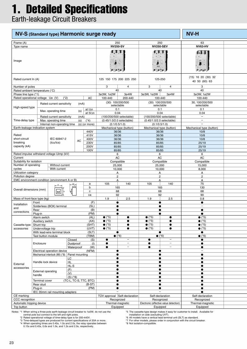
NV-S (Standard type) Harmonic surge ready
23
Notes: *1 When wiring a three-pole earth-leakage circuit breaker to 1ø2W, do not use the central pole but connect to the left and right poles.
*2 Rated operational voltage of time-delay type is for 200-440V.*3 Time-delayed types are produced for current specifications of 20A or more.*4 When operating times are 0.45s, 1.0s and 2.0s, the relay operates between
0.15s and 0.45s, 0.6s and 1.0s, and 1.2s and 2.0s, respectively.
*5 The cassette-type design makes it easy for customer to install. Available for installation on side (excluding UVT).
*6 All models have a vertical lead terminal unit (SLT) as standard.*7 For other models, please order in conjunction with the circuit breaker.*8 Not isolation-compatible.
250NV250-SEV
125-250
100-440
(30) 100/200/500selectable
0.10.04
(100/200/500 selectable)(0.45/1.0/2.0 selectable)
(0.1/0.5/1.0)Mechanical type (button)
0.10.04
–––
Mechanical type (button)36/3636/3636/3685/8585/8585/85
6AC
Compatible25,00010,000
A2A
10/810/810/8
25/1925/1925/19
6AC
Compatible15,0008,000
A2A
63NV63-HV
7513068900.8
(15) 16 20 (30) 3240 50 (60) 63
Self-declarationRecognized
Thermal-magneticEquipped
●–●
●
● (*5)● (*5)● (*5)● (*5)
●
● (*6)●
●
●–●
●
●
●
●
●
●
●
●
●
●
3 4
3ø4W3ø3W, 1ø2W
3 4
3ø4W3ø3W, 1ø2W
30, 100/200/500selectable
100-440
34040 40
3ø3W, 1ø2W
Self-declarationRecognized
Electronic (effective value detection)Equipped
●
●
●
●
●
●
●
●
●
●
●
●
●
●
●–
●
● (*6)●
● (*6)
1.9 2.51.9 2.5
105 1401656892
● (*5)● (*5)● (*5)● (*5)
●
●
●
●
● (*5)● (*5)● (*5)● (*5)
●
●
●
●
●
●
●
–––
●
●
●
–––
TÜV approval Self-declaration
105 140
250NV250-SV
125 150 175 200 225 250
100-440 200-440
36/3636/3636/3685/8585/8585/85
6AC
Compatible25,00010,000
A2A
RecognizedThermal-magnetic
Equipped
●
●
●
●
0.10.04
(100/200/500 selectable)(0.45/1.0/2.0 selectable)
(0.1/0.5/1.0)Mechanical type (button)
(30) 100/200/500selectable
●
●
●
●
●
●
●
●
●
●
●–
1656892
Rated current In (A)
Number of polesRated ambient temperature (°C)
Rated operational voltage Ue (V) (*2)Phase line type (*1)
Rated impulse withstand voltage Uimp (kV)
Suitability for isolationCurrent
Number of operatingcyclesUtilization category
IEC 60947-2(Icu/Ics)
Ratedshort-circuitbreakingcapacity (kA)
High-speed typeat IΔnat 5IΔn
Time-delay type
Earth-leakage indication system440V415V400V230V200V100V
abcca
Enclosure
Electrical operation device
ClosedDustproofWaterproof
(S)(I)
(W)
Mechanical interlock (MI) (*8) Panel mounting
Handle lock deviceLCHLHL-S
External operating handle
(F)(V)(S) (*8)
Without currentWith current
AC
Image
Frame (A)Type name
Terminal cover
Trip button
CE markingCCC recognitionAutomatic tripping device
IEC 35mm rail mounting adapters
(TC-L, TC-S, TTC, BTC)(B-ST)
(PM)
(NFM)
(F)(SL)(B)
(PM)(AL)(AX)
(SHT)(UVT)(SLT)
(TBM)
FrontSolderless (BOX) terminalRearPlug-inAlarm switchAuxiliary switchShunt tripUndervoltage tripWith lead-wire terminal blockTest button module
a
b
cac
Pollution degree
Overall dimensions (mm)
Mass of front-face type (kg)
External accessories
Rear studPlug-in
EMC environment condition (environment A or B)
AC
Installation and connections
Cassette-type accessories
Rated current sensitivity (mA)
Rated current sensitivity (mA)
Max. operating time (s)
Max. operating time (s) (*4)Internal non-operating time (s) (or more)
NV-HNV-S (Standard type) Harmonic surge ready
1. Detailed SpecificationsEarth-leakage Circuit Breakers

24
Remarks: 1. Products with rated current parenthesized are produced when an order is placed.2. The circuit breakers will be delivered with rated current sensitivity set to 500mA and
operating time of time-delayed types to 2.0s unless otherwise specified.3. Specify “P-LT” when using a plug-in product with a lead-wire terminal block
(excluding 63A frame or smaller). 4. The circuit breaker has the rated short-circuit breaking capacity specified in the
shaded cells.
(5) Rated operational voltage100-240V100-440V200-440V
100-200-415V200-415V
Applicable circuit voltage100/110/200/220/230/240V
100/110/200/220/240/254/265/380/400/415/440V200/220/240/254/265/380/400/415/440V
100/110/200/220/240/254/265/380/400/415/440V200/220/240/254/265/380/400/415/440V
Available voltage range80~264V80~484V160~484V80~484V160~484V
6AC
Compatible25,00010,000
A2A
125NV125-HV
(15) 16 20 (30) 32 40 50 (60) 63(75) 80 100 125 (*3)
Self-declarationRecognized
Thermal-magneticEquipped
●
●
●
●
125NV125-HEV
250NV250-HV
250NV250-HEV
100-440 200-440 100-440 200-440
30, 100/200/500selectable
0.10.04
(100/200/500 selectable)(0.45/1.0/2.0 selectable)
(0.1/0.5/1.0)Mechanical type (button)
50/3850/3850/38100/75100/75
3 4
3ø4W3ø3W, 1ø2W
3 4
3ø4W3ø3W, 1ø2W
3 4
3ø4W3ø3W, 1ø2W
3 4
3ø4W3ø3W, 1ø2W
–
40 40 40 40
●
●
●
●
●
●
●
●
●
●
●–
(30) 100/200/500selectable
0.10.04
(100/200/500 selectable)(0.45/1.0/2.0 selectable)
(0.1/0.5/1.0)Mechanical type (button)
63-125
100-440
65/6570/7075/75
100/100100/100100/100
6AC
Compatible25,00010,000
A2A
30, 100/200/500selectable
0.10.04
(100/200/500 selectable)(0.45/1.0/2.0 selectable)
(0.1/0.5/1.0)Mechanical type (button)
125 150 175 200 225 250
65/6570/7075/75
100/100100/100100/100
6AC
Compatible25,00010,000
A2A
Self-declarationRecognized
Thermal-magneticEquipped
●
●
●
●
●
●
●
●
●
●
●
●
●
●
●–
(30) 100/200/500selectable
0.10.04
(100/200/500 selectable)(0.45/1.0/2.0 selectable)
(0.1/0.5/1.0)Mechanical type (button)
125-250
100-440
65/6570/7075/75
100/100100/100100/100
6AC
Compatible25,00010,000
A2A
Self-declarationRecognized
Electronic (effective value detection)Equipped
●
● (*6)
● (*5)● (*5)● (*5)● (*5)
●
●
●
●
Self-declarationRecognized
Electronic (effective value detection)Equipped
●
●
●
●
●
●
●
●
●
●
●–
–
●
●
––
●
●
●
–––
●
●
●
●
●
● (*6)
1.9 2.5
105 1401656892
● (*5)● (*5)● (*5)● (*5)
●
●
●
●
●
●
●
●
●
●
●
●
●
●
●–
–
●
●
––
–
●
●
––
●
●
●
●
●
● (*6)
● (*5)● (*5)● (*5)● (*5)
●
●
●
●
●
● (*6)
● (*5)● (*5)● (*5)● (*5)
●
●
●
●
1.9 2.5
105 1401656892
1.8 2.5
105 1401656892
1.1 1.4
90 1201306890
100/75
(High-performance type) Harmonic surge ready

25
Notes: *1 The cassette-type design makes it easy for customer to install. Available for installation on side (excluding UVT).
*2 Not isolation-compatible.
Number of polesRated ambient temperature (°C)Rated insulation voltage Ui (V)
Rated impulse withstand voltage Uimp (kV)
Suitability for isolationReverse connection
Current
Number of operating cyclesUtilization category
IEC 60947-2(Icu/Ics)
Ratedshort-circuitbreakingcapacity (kA)
440V415V400V380V230V
abcca
Enclosure
Electrical operation device
ClosedDustproofWaterproof
(S)(I)
(W)
Mechanical interlock (MI) (*2) Panel mounting
Handle lock deviceLCHLHL-S
External operating handle
(F)(V)(S) (*2)
Without currentWith current (440VAC)
AC
Rated current In (A)Rated motor capacity (kW)
Frame (A)Type name
Terminal cover
Trip button
CE markingCCC recognitionAutomatic tripping device
IEC 35mm rail mounting adapters
(TC-L, TC-S, TTC, BTC)(B-ST)
(PM)
(NFM)
(F)(B)
(PM)(AL)(AX)
(SHT)(UVT)(SLT)
FrontRearPlug-inAlarm switch (*1)Auxiliary switch (*1)Shunt trip (*1)Undervoltage trip (*1)With lead-wire terminal block
a
b
cac
2.5/2.52.5/2.5
5/55/5
7.5/7.58
ACCompatible
Possible10,0006,000
A3
N/A75
1306890
0.65
Pollution degree
Overall dimensions (mm)
Mass of front-face type (kg)
Rear studPlug-in
EMC environment condition (environment A or B)
32NF32-SV
Self-declarationRecognized
Thermal-magneticEquipped
●
●
●
●
●
●
●
●
●
●
●–●
●
●
●
●
●
●
●
●
●
●
500
340
32
A
7.5 15
200/220VkW
400/440VkW
251612108
7.154
5.53.7–
2.2–
1.5–
0.75
117.55.5–
3.7–
2.21.5
NF63-CV50
NF63-SV
2.5/2.52.5/2.5
5/55/5
7.5/7.58
ACCompatible
Possible10,0006,000
A3
N/A75
1306890
0.65
Self-declarationRecognized
Thermal-magneticEquipped
●
●
●
●
●
●
●
●
●
●
●–●
●
●
●
●
●
●
●
●
●
●
500
3
Self-declarationRecognized
Thermal-magneticEquipped
●
●
●
●
●
●
●
●
●
●
●–●
●
●
●
●
●
●
●
●
●
●
500
340
454032251612108
A
11–
7.55.53.7–
2.2–
2218.515117.55.5–
3.7
200/220VkW
400/440VkW
7.154
A
1.5–
0.75
–2.21.5
200/220VkW
400/440VkW
7.5/7.57.5/7.57.5/7.57.5/7.515/15
8AC
CompatiblePossible15,0008,000
A3
N/A75
13068900.7
Installation and connections
Cassette-type accessories
External accessories
NF - MB (Motor breakers)
1. Detailed SpecificationsMotor-protection Breakers

26
Remarks: 1. The motor circuit breakers do not have an applicable rated motor capacity. Select a motor circuit breaker based on the total load current of the motor.
2. Products with rating parenthesized are produced when an order is placed.
3. Specify “P-LT” when using a plug-in product with a lead-wire terminal block.
4. The circuit breaker has the rated short-circuit breaking capacity specified in the shaded cells.
100NF125-SV
225NF250-SV
10090716345
(40)32
(25)(16)
(12.5)
A
–22
18.51511–
7.55.53.7–
55453730221915117.55.5
200/220VkW
400/440VkW
225200175150125
A
55–
453730
110–
9075–
200/220VkW
400/440VkW
Self-declarationRecognized
Thermal-magneticEquipped
●
●
●
●
●
●
●
●
●
●
●
●
●
●
●
●
●
●
●
●
●
●–
500
340
25/2530/3030/3030/3050/50
8AC
CompatiblePossible25,00010,000
A3
N/A901306890
0.95
TÜV approvalRecognized
Thermal-magneticEquipped
●
●
●
●
●
●
●
●
●
●
●
●
●
●
●
●
●
●
●
●
●
●–
500
340
36/3636/3636/3636/3685/85
8AC
CompatiblePossible25,00010,000
A3
N/A10516568921.6

27
Mag Only (Instantaneous tripping circuit breakers)
DC MCCBs and DSN SwitchesBreaking is more difficult with direct currents because the current value never reaches zero. While ordinary DC breakers are suitable for low voltages, special-voltage DC breakers are recommended for voltages in excess of 250VDC. Breakers for 550V are all 4-pole models.The size, shape, drilling plan, accessories, etc., are all identical to the S Series breakers with the same designations.
These breakers are designed as thyristor-Leonard system DC-side breakers. They protect the thyristor from short circuiting when there is a power or communication failure (Mag-only breakers can also be used for this purpose). Use these breakers in combination with fast fuses for even greater protection.
Wiring diagram for DC use.
● DC side
Fixed10 times rated current
(AC) (DC)
NF63-CV/SV/HV AC, DC
NF125-CV/SV/HV AC, DC
NF250-CV/SV/HV AC, DC
Remarks: 1. The size, weight, accessories, etc., are all identical to the same-designation C, Sand H Series breakers.
2. For more details, please contact your dealer.
Remark: 1. The tripping characteristics will change if the wiring differs from that shown here.
AC, DC
Wiring diagram for DC use
NF125-SGV/LGV/HGVNF160-SGV/LGV/HGVNF250-SGV/LGV/HGV
TypeNumber of polesRated voltage (VDC)Rated breaking capacity (kA)IEC 60947-2 (Icu/Ics)
NF63-SV NF125-SV3
4404
5503
4004
550
2/2 10/10 20/20
NF250-SV3
5004
600
Remark: 1. Time constant: 10ms or below.
TypeNumber of polesRated voltage (VDC)
Instantaneous trip current (min.)
NF125-SV NF250-SV
3 times rated current
2300
3500
3 times rated current
2250
40/40
3440
10/10Rated breaking capacity (kA)IEC 60947-2 (Icu/Ics)
These are standard MCCBs without the automatic tripping element. The tripping capacity is approximately six times the rated current. The appearance, size, drilling plan and available accessories are all identical to similar standard S and C Series MCCBs.
● DSN switches
Type DSN63-CV DSN125-CV DSN250-CVRated current (A) 63 125 052Number of poles 32 2 3 2 3Rated voltage (AC/DC) 052/005 052/005 052/005
378/155 013/057 526/0051Max. switching current (AC/DC)
Rated current (A)
Number of poles
Rated voltage (AC/DC)
Max. switching current (AC/DC)
DSN32-SV DSN63-SV DSN125-SV DSN250-SV32 125
2 3
500/250
192/80 750/310
63
500/250 690/250
378/155
2 3 2 3 4
DSN125-SGV125
750/315
690/300
2 3 4
DSN160-SGV160
960/400
690/300
2 3 4250
1500/625
690/250
2 3 4
DSN250-SGV250
1500/625
690/300
2 3 4
Type
20/20
2. Special-purpose BreakersMag Only, DC and DSN

28
400Hz MCCBs
Low-instantaneous MCCBs
Standard MCCBs cannot be used in 400Hz circuits. When standard MCCBs are used in high-frequency circuits (eq. 400Hz), the instantaneous characteristics are shifted higher. The 400Hz MCCB is recommended for use in 400Hz circuits.
Generator Protection MCCBsThese breakers are designed for generator protection.
When a power fuse (PF) is used for high-voltage protection, make sure that the MCCB on the secondary side is compatible.
● Low-Inst. MCCBs for Discrimination
● Specifications
The appearance, size, rated interrupting capacity, drilling plan, accessories, etc., are all identical to the standard S and H Series breakers of the same designation.
● Specifications
NF125-SV NF125-HV NF250-SV
16, 20, 32, 40, 50, 63,80, 100
16, 20, 32, 40, 50, 63,80, 100
125, 150175, 200
2 3 4 2 3 4 2 3 4 2 3 4
8/818/1825/2530/3050/50
8/830/3036/3636/3685/85
10/830/2350/3850/38100/75
NF250-HV
125, 150175, 200
10/850/3865/6575/75
100/100
Type
Rated current (A)
Rated current (A)
Number of poles
Number of poles
Rated insulation voltage (V)
Rated breaking capacity(kA)IEC 60947-2 (Icu / Ics)
690VV005V044V004V032
690
● Specifications
NF125-CV
2 3 2 3 4 2 3 2 3 4
,08,36,05100, 125
04,23,02,61100,125,08,36,05
571,051,521052,522,002
571,051,521052,522,002
Instantaneous trip(% of rated current)
006 ● ● ● ●
004 — — ● ●
NF125-SV NF250-CV NF250-SV
Remarks: 1. Ensure compatibility with motor, etc., before use to prevent accidental tripping at start up.2. Specify rated current and tripping characteristics.3. There are no short time delay characteristics.
The appearance, size, rated interrupting capacity, accessories, etc., are all identical to the standard instantaneous trip breakers of the same designation.
Type PF
Tr1
MCCB 1
MCCB 2
Tim
eCurrent
Low-inst. MCCBs
MCCBoperatingcharacteristiccurve
PF short-time tolerance capacity
Fig. 4.12 Low-inst. MCCB characteristics
Number of poles 3
16-3232-6363-125
adjustable
16-3232-6363-125
adjustable
80-160125-250
adjustable
80-160125-250
adjustable
3
300 (*1)
18~28 (*1)
690
3 3
Rated current (A)
Instantaneous trip (% of rated current)
Operating time at 150% of rated current (s)
Rated insulation voltage (V)
Rated breakingcapacity(kA)
IEC 60947-2(Icu/Ics)
690VAC
500VAC
440VAC
400VAC
230VAC
8/8
30/30
36/36
36/36
85/85
10/8
50/38
65/65
75/75
100/100
8/8
30/30
36/36
36/36
85/85
10/8
50/38
65/65
75/75
100/100
Type
Note: *1 The MCCB operating characteristics must be adjusted as follows.STD ≤ 3 (Is setting)LTD: minimum setting (TL = 12s setting)
NF125-SEV NF125-HEV NF250-SEV NF250-HEV
2. Special-purpose Breakers400Hz, Instantaneous and Generator Protection

29
2. Special-purpose BreakersMDU Breakers
Measuring Display Unit (MDU)Circuit breakers and measurement display units are integrated.With built-in VT and CT, the circuit breaker requires less space and contributions are made to reduced work and energy savings.
Features
Combination
NF250-SEV/HEV with DP
NF250-SEV/HEV
Module (power input)
Module (power input + transmission)
Module (pre-alarm)
MDU-DP-N (display)
MDU-DP-C (display + network)
Measuring
Display 14
Transmission 2
Alarm
CC-Link
Pulse output (electric energy)
Load current
Line voltage
Power (active/reactive)
Energy (active/reactive)
Harmonic current
Power factor
Frequency
OVER
Trip cause (LTD, STD, INST) & trip current
Pre-alarm
Display (DP) on the
breaker
1-a
2-a
●
●
●
●
●
●
●
●
●
–
–
–
1 1 14
14
2 2
3 3
1-a
2-b
●
●
●
●
●
●
●
●
●
–
●
●
1-a
2-a
3
●
●
●
●
●
●
●
●
●
●
–
–
1-a
2-b
3
●
●
●
●
●
●
●
●
●
●
●
●
1-b
4-a
●
●
●
●
●
●
●
●
●
–
–
–
1-b
4-b
●
●
●
●
●
●
●
●
●
–
●
●
1-b
3
4-a
●
●
●
●
●
●
●
●
●
●
–
–
1-b
3
4-b
●
●
●
●
●
●
●
●
●
●
●
●
Panelboard
mounting
Type
Frame (A)
Number of poles
Suitability for use
Rated insulation voltage (V)
Rated current (A)
Rated
short-circuit
breaking capacities (kA)
IEC60947-2 (Icu/Ics)
AC
690V
500V
440V
415V
400V
380V
230V
200V
Reverse connection
Installation and connections
Cassette-type accessories
External accessories (*1)
Front connection (F)
Rear connection (R)
NF250-SEV with MDU
250
690
125-250A (adjustable)
8/8
18/18
36/36
36/36
36/36
36/36
85/85
85/85
–
●
●
Refer to P.16
Refer to P.16
3
3ø3W
4
3ø4W
NF250-HEV with MDU
250
690
125-250A (adjustable)
10/8
30/23
50/50
70/70
75/75
75/75
100/100
100/100
–
●
●
Refer to P.18
Refer to P.18
3
3ø3W
4
3ø4W
●A low-voltage circuit breaker combines an MDU for measuring, displaying, and transmitting information on cable ways, and closely monitors energy consumption by measuring current, voltage, power, electric energy, harmonic current, leakage current, power factor, etc., to assist in energy savings.
●Since the circuit breaker saves its tripping information (causes and current values), causes of accidents can be investigated and corrected sooner.
Note: *1 For models with DP, the accessories below are not applicable.Electrical operation device (NFM)Mechanical interlock (MI)External operating handle (F, V, S)Handle lock device (HL-S)Enclosure (S, I, W)

30
Front connection
Rear connection
Breaker mounting
Display on the circuit breaker body
MDU Terminal
Neutralpole
Neutralpole
Mtg platet max.=3.2
Mtg platet max.=3.2
Insulationtube
Insulationtube
Insulationtube
Connectionallowance
Insulationtube
Connectionallowance
Operatingcharacteristicsselector
Operatingcharacteristicsselector
Breaker mounting
M8 bolt(hex-socket)
TripButton
TripButton
Stud can berotated 90°
Stud can berotated 90°
Breaker mounting
1mm clearanceon each sideof handle
Panel mounting
Panel mounting
Insulation barrier(removable)
Mtg hole Mtg hole
ø9M8 bolt
M4×0.7breakermtg screw
Front-plate cutout
1mm clearanceon each sideof handle
Front-plate cutout
Breaker
3-pole 4-pole
M4×0.7breakermtg screw
ø9M8 bolt
3-pole 4-pole
Insulation barrier(removable) M8 bolt
(hex-socket)
Breaker
M3 screw
Connector(removable)
Controlpower P1
Controlpower P2
Controlpower FG
72
3-pole
4-pole
100
35105140
2270
105
10032.5
52
R1
MDU unit
50102
45
61
68
2270
72
22
4
144
6
70105
92
61
68
77
86.5
38.5
45
24
MDU unit
3-pole4-pole
3-pole
68 71
1515
20
4-pole
144
165
100
100
3(65)
24
2513
3
18
8
100
32.5
R1
39.5
88.5
102
2214
4
6
7010568 71
1515
20
8
106
92
ø8.
5
ø8.
5
ø4.
5
ø4.
5
3-pole
4-pole
77 106
165
144
100
105
35105140
· MDU terminal
1 2 3 4 5 6
In the figure below the terminal cover is removed.
––
– – ––
No transmissionPulse outputCC-Link
––––––
114 113DADBDGSLD
1 2 3 4 5 6

31
2. Special-purpose BreakersMDU Breakers
Front connection
Rear connection
MDU panel mounting
MDU Terminal for panel mountingPanel mounting
· MDU terminal
1
1 2 3 4 5 6
2 3 4 5 6 P2 P1Control power
––114113 ––
Terminal block
No transmissionPulse outputCC-Link
–––––
DA DB DG SLD FGFGFG
In the figure below the terminal cover is removed.
Panel holder plate
90
70
91
14.5
35
Front-panel cutout
Operation and display side90
90
72
72
R2
MDU connector
*Panelthickness1~3.2mm
70 90
Neutralpole
Bus drilling fordirect connection
Mtg platet max.=3.2
Insulationtube
Insulationtube
Connectionallowance
Operatingcharacteristicsselector
(Bus t max.=7)
TripButton
Stud can berotated 90°
3-pole 4-poleDrilling plan
Panel mounting
Panel mounting
Mtg hole Breaker
Drilling plan
M4×0.7or ø5
M4×0.7or ø5
ø24
1mm clearanceon each sideof handle
Front-plate cutout
3-pole 4-pole
Breaker
M4×0.7breakermtg screw
ø9M8 bolt
3-pole 4-pole
Insulation barrier(removable) M8 bolt
(hex-socket)
Breaker
72
100
35105140
2270
105
10032.5
52
R1
50102
45
61
68
724
92
126
3535
24
3-pole
7035
3535
105
4-pole
22
144
6
7010568 71
1515
20
8
106
ø8.
5
ø4.
5
3-pole
4-pole
126
144
165
144
100
25max.
25max.
ø8.5or
910
C1
ø8.5
C1
32
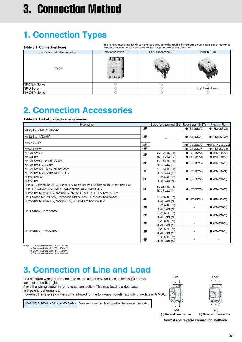
The standard wiring of line and load on the circuit breaker is as shown in (a) normal connection on the right. Avoid the wiring shown in (b) reverse connection. This may lead to a decrease in breaking performance. However, the reverse connection is allowed for the following models (excluding models with MDU).
1. Connection Types
2. Connection Accessories
3. Connection of Line and Load
NF-C, NF-S, NF-H, NF-U and MB Series Reverse connection is allowed for the standard models.
Table 3-1: Connection types
Table 3-2: List of connection accessories
Image
Front connection (F) Rear connection (B) Plug-in (PM)
NF-C/S/H SeriesNF-U SeriesNV-C/S/H Series
Connection method (abbreviation)
The front connection model will be delivered unless otherwise specified. Front connection models can be converted to other types using an appropriate connection component (separately available).
NF32-SV, NF63-CV/SV/HV
NV32-SV, NV63-HV
NV63-CV/SV
NF63-SV/HVNF125-CV/SVNF125-HVNF125-CV/SV, NV125-CV/SVNF125-HV, NV125-HVNF125-SV, NV125-SV, NF125-ZSVNF125-HV, NV125-HV, NF125-ZHVNF250-CV/SVNF250-HVNF250-CV/SV, NF125-SEV, NF250-SEV, NF125-SGV/LGV/HGV, NF160-SGV/LGV/HGV, NF250-SGV/LGV/HGV, NV250-CV/SV, NV125-SEV, NV250-SEV
NF125-SEV, NV125-SEV, NF250-SV, NF250-SEV, NV250-SV, NV250-SEVNF250-HV, NF250-HEV, NV250-HEV, NF125-HEV, NV125-HEV
NF125-RGV, NF250-RGV
NF125-UGV, NF250-UGV
NF250-HV, NF250-HEV, NV250-HV, NV250-HEV, NF125-HEV, NV125-HEV
2P
3P
2P
3P
4P
2P
3P
2P
3P
4P
4P
2P
4P
2P
3P
Type name Rear studs (B-ST)
(ST-05SV2)
(ST-05SV3)
(ST-05SV2) (ST-05SV4) (ST-1SV2) (ST-1HV2)
(ST-1SV3)
(ST-1SV4)
(ST-2SV2)
(ST-2SV3)
(ST-2SV4)
–
–
–
–
–
(PM-05SV2)
(PM-05SV3)
(PM-NV05SV2) (PM-05SV4) (PM-1SV2) (PM-1HV2)
(PM-1SV3)
(PM-1SV4)
(PM-2SV2)
(PM-2SV3)
(PM-2SV4)
(PM-2SV2)
(PM-2SV3)
(PM-2UV2)
(PM-2UV3)
–
Plug-in (PM)
–
SL-1SV4L (*1)SL-1SV4G (*2)SL-1SV3L (*1)SL-1SV3G (*2)SL-1SV4L (*1)SL-1SV4G (*2)SL-2SV4L (*3)SL-2SV4G (*4)
SL-2SV4L (*3)SL-2SV4G (*4)SL-2SV4L (*3)SL-2SV4G (*4)SL-2SV3L (*3)SL-2SV3G (*4)SL-2UV4L (*3)SL-2UV4G (*4)SL-2UV3L (*3)SL-2UV3G (*4)SL-2UV4L (*3)SL-2UV4G (*4)
SL-2SV3L (*3)SL-2SV3G (*4)
Solderless terminal (SL)
Line
Line
Load
Load
(a) Normal connection
Normal and reverse connection methods
(b) Reserve connection
(2P and 3P only)
Notes: *1 Connected wire size : 2.5 ~ 25mm2
*2 Connected wire size : 25 ~ 70mm2
*3 Connected wire size : 14 ~ 95mm2
*4 Connected wire size : 70 ~ 125mm2
3. Connection Method

33
4. AccessoriesInternal Accessories
1. Accessories
2. Switch Operation and RatingTable 4-2: AL switch operation Table 4-4: AL·AX switch rating
Table 4-3: AX switch operation
Please contact us regarding applications requiring smaller current values.
98/ALa (open)96/ALb (closed)95/ALc
98/ALa (closed)96/ALb (open)95/ALc
14/AXa (open)12/AXb (closed)11/AXc
14/AXa (closed)12/AXb (open)11/AXc
Table 4-1: Accessories
Alarm switch
Auxiliary switch
Shunt trip
Undervoltage trip
Test button module(*1)
Pre-alarm module
Internal accessories Function Applicable models Cassette-typeaccessories
Electrically indicates the trip status of the circuit breaker.
Electrically indicates the ON/OFF status of the circuit breaker.
Electrically trips the circuit breaker from a remote distance. Permissible working voltages are 70 to 110% of the AC rated voltage or 70 to 125% of the DC rated voltage.
Automatically trips the circuit breaker if the voltage is lowered. Working voltages are 70 to 35% of the UVT rated voltage. When the voltage recovers to 85% or higher, it is possible to reset the device and restart operation.
Allows remote testing through application of a voltage.An external sequence common to SHT can be used. (The standard configuration requires the vertical lead-wire terminal unit (SLT).)
Indicates that the load current exceeds the pre-alarm setting current.
NF-C/S/H/UNV-C/S/H/U
NF-C/S/H/UNV-C/S/H/U
NF-C/S/H/UNV-C/S/H/U
NV-C/S/H
Electronic type
Circuit breaker statusSwitchtype
S
AL switch contact
AX switch contactCircuit breaker status
OFF or ON
OFF or Trip
ON
Trip
Voltage
(V)
Current (A)
460
250
125
Voltage
(V)
250
125
30
Resistive load
––
3
5
Inductive load
––
2
3
Current (A)
Resistive load
0.2
0.4
4
Inductive load
0.2
0.4
3
AC DC
–
–

34
3. Maximum Number of Internally Mounted Accessories
Table 4-9: Combinations of accessories
Notes: *1 Models with UVT require a UVT voltage module to be installed on the lead-wire terminal unit (no such voltage module is required for SHT).*2 Second AX can be substituted for the AL on the left pole. *3 SHT and UVT for left-pole installation can be produced if specified.*4 Only the models with an SLT are available. EAL and PAL require a control power supply (shared 100 - 200VAC).
For the 24VDC TBM only, please specify control voltage (the standard shared voltage is 100 - 240VAC/100 - 240VDC).
Remarks: 1. Circled numbers indicate the order of installation.2. Accessories of EAL, and TBM can be installed independent of installations of AL, AX, and MG (two units among EAL and TBM cannot be installed at the same time).
Poles
AL/AX (standard) switches
AL
AX
AL + AX
SHT or UVT
AL + SHT or UVT
AX + SHT or UVT
AL + AX + SHT or UVT
TBM
C
S
H
U
HandleLeft-sidemounting
Right-sidemounting
AL AX SHT or UVT
Lead-wire direction
Cassette-type accessories
TBM
(*1)
2
(*1) (*3)
2, 3, 4
S
2, 3, 4
(*2)
(*1)
(*4)
(*2)
(*1)
(*1)
(*1)
NF63-CV, NF125-CV NF63-CV, NF125-CV, NF250-CV NV63-CV, NV125-CV, NV250-CV
NV32-SV, NV63-SV, NV125-SV, NV125-SEVNV250-SV, NV250-SEV
NV63-HV, NV125-HV, NV125-HEVNV250-HV, NV250-HEV
NF32-SV, NF63-SV, NF125-SVNF125-SEV, NF125-SGV, NF160-SGVNF250-SV, NF250-SEV, NF250-SGVNF125-LGV, NF160-LGV, NF250-LGV
NF63-HV, NF125-HV, NF125-HEVNF125-HGV, NF160-HGVNF250-HV, NF250-HEV, NF250-HGV
NF125-RGV, NF125-UGVNF250-RGV, NF250-UGV
NF32-SV, NF63-SV, NF125-SV
NF63-HV
NFSeries
Type
NV

35
4. AccessoriesInternal Accessories
4. Shunt Trip (SHT)Table 4-10: Standard coil rating
Notes: *1 Secure a sufficient input power so that the voltage will not drop below the permissible lower working voltage (70% of the lowest rated voltage).*2 The operating time denotes the time from when the rated voltage is applied to SHT until when the main contact of the breaker starts to open.
5. Undervoltage Trip (UVT)
Table 4-11: Standard coil rating ● UVT Voltage Module
Notes: *1 The operating time denotes the time from when no voltage is applied to UVT until when the main contact of the breaker starts to open.
*2 Time-delayed types can be produced. Details are available on request.
6. Test Button Module (TBM)
8. Vertical Lead-wire Terminal Block (SLT)
Table 4-12
Note: *1 100-240VAC and 100-240VDC specifications are standardunless otherwise specified.Specifications for 24VDC are available on request.
J1
J2
UVT voltage module wiring diagram(lead-wire connection)
100V100-125V
Input power
VA
5
Operating time (ms)
(*1) (*2)
30 or less
Series
All models
Voltage
100-130VAC/VDC (*1)
200-250VAC
380-480VAC
(Compatible to 50 and 60Hz)
Series
Input rated
control voltage
Input control power (VA)
NV-C/S/H,
Compatible with
100-240VAC/VDC
24VDC (*1)
1.5 or less
Circuitbreaker
18
7
12.5
18
M3.5M3.5 terminal screw
86.5
TBM2TBM1
10.5
(10.
5)
87 (T
erm
inal
cov
er)
UVT voltage module
D1
J1
J2
D2
● Press the test button on the main body of the breaker while control voltage is applied to test the unit. The voltage must be applied to the main body of the breaker for more than two seconds when testing time-delayed NV models
● All models have a vertical lead terminal unit (SLT) as standard
● The circuit beaker can be mounted, and closely fitted, to the unit● Terminal screws are arranged in a zigzag pattern, and screws can be tightened further after wiring● A terminal cover is provided● For front connection, rear connection and plug-in models (excluding PLT)
7. Lead-wire SpecificationsTable 4-13
Note: *1 400mm for models with four poles and right-pole installation.
Type
Heat-resistant
wire
Size
0.5mm2
Length
(*1)
450mm
Ring-mark exampleMarking
A ring-mark with the terminal symbol is attached to each lead wire
All models
Series
Equipped
Cut-off switch Voltage
100-240VAC380-550VAC(Compatible to 50 and 60Hz)100-125VDC
120 15 or less
100V 240V 380V 550V
AC DC
50
Input power requirement (VA) (*1)
Operating time (ms) (*2)
The UVT voltage module is normally installed on the vertical lead-wire terminal unit (SLT) (a separate-mount type can be produced on request).
98/ALa , 96/ALb , 95/ALc
C1/S1 , C2/S2
● Lead wires are normally extended laterally● Grooves are provided on the side of the breaker for extending lead wires on the side of the breaker
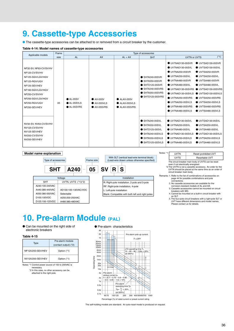
36
10. Pre-alarm Module (PAL)
Voltage
Model name explanation Notes: *1
The circuit breaker main body of UVTS can be reset even if not electrically energized.
*2 The UVTN is not a cassette accessory. An order for the UVTN should be placed at the same time as an order of circuit breaker main body.
Remarks: 1. Refer to the list of combinations of accessories on page 44 for possible combinations and pole connections.
2. No cassette accessories are available for the corrosion-resistant models of AL and AX.
3. Cassette accessories cannot be mounted on circuit breakers with MG.
4. Cannot be mounted on a built-in circuit breaker with an SLT.
5. The four-pole circuit breakers with a right-pole SLT or UVT have different dimensions and model names. Please contact us for details.
● The cassette-type accessories can be attached to or removed from a circuit breaker by the customer.
Type of accessories Frame sizeWith SLT (vertical lead-wire terminal block)
(Lead-wire drawn unless otherwise specified)
SHT A240 05 SV R S
UVTN
UVTS
Reset prohibited UVT
Resettable UVT
SHT
A240:100-240VAC
A440:380-440VAC
A550:380-550VAC
D100:100VDC
D125:100-125VDC
Installation
UVTN, UVTS (*1)(*2)
AD130:100-130VAC/VDC
Selectable
A250:200-250VAC
A480:380-480VAC
NF32-SV, NF63-CV/SV/HV
NF125-CV/SV/HV
NF125-SGV/LGV/HGV
NF125-RGV/UGV
NF125-SEV/HEV
NF160-SGV/LGV/HGV
NF250-CV/SV/HV
NF250-SGV/LGV/HGV
NF250-RGV/UGV
NF250-SEV/HEV
AL-05SV
AL-05SVLS
AL-05SVRS
AX-05SV
AX-05SVLS
AX-05SVRS
ALAX-05SV
ALAX-05SVLS
ALAX-05SVRS
SHTA240-05SVR
SHTA550-05SVR
SHTD125-05SVR
SHTA240-05SVRS
SHTA550-05SVRS
SHTD125-05SVRS
UVTNAD130-05SVR UVTSAD130-05SVR
UVTNAD130-05SVL UVTSAD130-05SVL
UVTNA250-05SVR UVTSA250-05SVR
UVTNA250-05SVL UVTSA250-05SVL
UVTNA480-05SVR UVTSA480-05SVR
UVTNA480-05SVL UVTSA480-05SVL
UVTNAD130-05SVRS UVTSAD130-05SVRS
UVTNAD130-05SVLS UVTSAD130-05SVLS
UVTNA250-05SVRS UVTSA250-05SVRS
UVTNA250-05SVLS UVTSA250-05SVLS
UVTNA480-05SVRS UVTSA480-05SVRS
UVTNA480-05SVLS UVTSA480-05SVLS
05
AL AL + AX SHT UVTN or UVTS
Type of accessories
AX
NV32-SV, NV63-CV/SV/HV
NV125-CV/SV/HV
NV125-SEV/HEV
NV250-CV/SV/HV
NV250-SEV/HEV
Applicable modelsFrame
size
SHTA240-05SVL
SHTA550-05SVL
SHTD125-05SVL
SHTA240-05SVLS
SHTA550-05SVLS
SHTD125-05SVLS
UVTNAD130-05SVL UVTSAD130-05SVL
UVTNA250-05SVL UVTSA250-05SVL
UVTNA480-05SVL UVTSA480-05SVL
UVTNAD130-05SVLS UVTSAD130-05SVLS
UVTNA250-05SVLS UVTSA250-05SVLS
UVTNA480-05SVLS UVTSA480-05SVLS
(*1)
● Pre-alarm characteristics
Ope
ratin
g tim
e
Table 4-14: Model names of cassette-type accessories
9. Cassette-type Accessories
R: Right-pole installation, 2-pole and 3-pole
RF: Right-pole installation, 4-pole
L: Left-pole installation
Blank: Compatible with both left and right poles
Table 4-15
● Can be mounted on the right side of electronic breakers
Notes: *1 Control power source of 100 to 200VAC is necessary.
*2 In this case, no other accessory can be attached to the right pole.
4h
2h
1h
30min20min
10min14min
6min4min
2min
1min
30s20s
10s
5s
2s
1s
0.5s
0.2s
0.1s
LTD operating time TL
12 – 60 – 80 – 100s ± 20%(at 200%)
Pre-alarmpickup current IpIr × (0.7 – 0.75 – 0.8 – 0.85– 0.9 – 0.95 – 1.0) ± 10%
Pre-alarmoperating time Tp
(at 200%)
Pre-alarm pick-up current
I6t =OFF
Tp= ± 20%TL
2
60 100 125 200 300 400 500600700 100070
Type
NF125/250-SEV/HEV
NV125/250-SEV/HEV
Option (*1)
Option (*1)
Pre-alarm module
(contact output) (*2)
Percentage (%) of rated current or preset current rating
The self-holding models are standard. An auto-reset model is produced on request.

37
1. F-type Operating Handle
Table 4-16 Summary of dimensions
●Appearance (Color N1.5)
Notes: *1 Shows dimensions for front connection types. For rear connection and plug-in types, the reference surface changes.
*2 Do not remove the sponge packing installed to ensure protection rating of IP54. Install the packing that comes with the operating handle.
*3 Operating the trip button can trip the circuit breaker with the door open (the trip button position differs from one model to another).
Remarks: 1. Products with “E” in the model numbers are for emergency stop devices.2. The standard models have reset-open specifications that allow the door to be opened
only when reset (open operation).Products with OFF-open specifications are made on request and allow the door to be opened in the OFF position.
3. Products with the same ON/OFF indication specifications as the standard models are made on request even if the circuit breaker is installed on its side.
Applicable models
Front plate
A±235
Plate thickness(1.2 to 3.2)
Center of circuit breaker and operating handle
Center of circuit breaker handle
Center of circuit breaker handle
Center of circuit breaker
(b) (a)
(b)(a)
(b) (c)
Either M4 × 0.7 screw or ø5
Either M4 × 0.7 screw or ø5
Circuit breaker
4-ø12
X1 X2
78
78
ø90
Hinge (left) Hinge (right)
Operating handleFront plate
(a)
C C
DD
OFF
TRI P P E D
O N LL
Packing
NEP O
RESET
B
B
●External dimension drawing
●Front plate drilling dimension drawing
●Circuit breaker mounting-hole drilling dimension drawing
●Center of hinge and circuit breaker
* The above drawing shows the layout of the hinge and the circuit breaker when viewed from the load side.
JTrip button
Trip buttonG
HTrip button
KTrip button
Center of circuit breaker and operating handle
Left hinge
L L
Less than 10
10 or more0 or more (5L + 85) or more
X1 X2
170 or more
(5L + 120) or more
Right hinge
Circuit breaker
F-05SV2
F-05SVE22 –
–
–
2/3
3/4
3/4
3/4
3/4
2/3/4
2/3/4
2
F-05SV
F-05SVE
F-1SV2
F-1SVE2
F-1SV
F-1SVE
F-2SV
F-2SVE
NF32-SV
NF63-CV, NF63-SV, NF63-HV
NF32-SV
NF63-CV, NF63-SV, NF63-HV
NV32-SV
NV63-CV, NV63-SV, NV63-HV
NV125-CV, NV125-SV, NV125-HV
NV125-SEV, NV125-HEV
NV250-CV, NV250-SV, NV250-HV
NV250-SEV, NV250-HEV
NF125-CV, NF125-SV
NF125-CV, NF125-SV
NF63-HRV, NF125-HV
NF125-SEV, NF125-HEV, NF125-SGV
NF125-LGV, NF125-HGV, NF125-RGV
NF160-SGV, NF160-LGV, NF160-HGV
NF250-CV, NF250-SV, NF250-HV
NF250-SGV, NF250-LGV, NF250-HGV
NF250-SEV, NF250-HEV, NF250-RGV
–
–
–
(b) (a)
(b) (a)
(c) (a)
(c) (a)
(c) (a)
105
12.5
25
111
126
15
30
35
104
107
J
J
K
H
H (a):
Breaker mounting
screws (2 pcs)
(b):
Breaker - operating
handle mounting
screws (2 pcs)
F-05SV2,
F-05SVE2,
F-1SV2 and
F-1SVE2
use (b) only.
Mountingscrews
Tripbutton
position
Dimensions (mm)
A(*1)
B C D
Drillingplans
Number of polesNumber of polesNVNFB
Typenames
Breaker-mounted operating handle installed on a circuit breaker main body
●Provides a circuit-disconnecting (isolating) function in combination with the breaker body
●Conforms to EN safety standards (EN 60204-1)● Includes as standard a safety device which prevents breaker
turning on when the cover is open●Can be locked in the OFF position (a padlock of 35mm or
40mm can be used and a model with ON/OFF lock only can be produced on request)
● IP54 rating (IEC 60529)
4. AccessoriesExternal Accessories

38
2. V-type Operating Handle
Table 4-17 Summary of dimensions
ETES R
FF O
DEPPIRT
NO
ø9
Center of circuit breaker and circuit breaker handle
F
E E
F F
E E
Front plate
Hinge (right)Hinge (left)
X X
ø54
54
54
54
61A
Front plate
Center of circuit breaker and operating handle
Center of circuit breaker and operating handle
D
D
(c) (d)
●External dimension drawing●Appearance (Color N1.5)
●Front plate drilling dimension drawing
●Adjustable Type
●Circuit breaker mounting-hole drilling dimension drawing
●Center of hinge and circuit breaker
Platethickness(1.2 to 3.2)
B (fixed type) ±2C (adjustable type) ± 2
LL
0 or more (5L + 100) or moreL X
(a)
Note: *1 For the adjustable type, the dimensions shown above are those when the adjustment unit V-AD3S (separately available) is mounted.
Remarks: 1. Please contact us regarding applicable models other than those mentioned above. 2. IP65 rating (IEC 60529).3. Operating the trip button can trip the circuit breaker with the door open
(the trip button position differs from one model to another).4. Products with “E” in the model numbers are for emergency stop devices.
Mounting the separately available adjustment unit V-AD3S to the built-in control settings, enables adjustment of the height between the breaker installation face and the panel door. Cut the shaft of the adjustment unit to fit the height.
Padlock
Lock hole
Operating section
Operating section
Warning mark
Joint
Shaft Joint clamp screw
During checkup and other times when the panel door is open, the operation lock can be used to prevent the breaker from being turned on by accident. Lock by passing a padlock through the lock hole of the operating section of the operating handle.
●Operation Lock While Panel Door Is Open
V-05SV2
V-05SVE22 – – –
– –
–
–
–
2/32/3
3
4
3
4
3
4
4
4
2/3
2/3
2
3
4
V-05SV
V-05SVE
V-1SV2
V-1SVE2
V-1SV
V-1SVE
V-2SV
V-2SVE
NF32-SV
NF63-CV, NF63-SV, NF63-HV
NF32-SV
NF63-CV, NF63-SV, NF63-HV
NV32-SV
NV63-CV, NV63-SV, NV63-HV
NV125-CV, NV125-SV, NV125-HV
NV125-SEV, NV125-HEV
NV250-CV, NV250-SV, NV250-HV
NV250-SEV, NV250-HEV
NF125-CV, NF125-SV
NF125-SVF
NF125-CV, NF125-SV
NF63-HRV, NF125-HV
NF125-SEV, NF125-HEV, NF125-SGV
NF125-LGV, NF125-HGV, NF125-RGV
NF160-SGV, NF160-LGV, NF160-HGV
NF250-CV, NF250-SV, NF250-HV
NF250-SGV, NF250-LGV, NF250-HGV
NF250-SEV, NF250-HEV, NF250-RGV
–
–
–
–
(b) (a)
(b) (a)
(c) (a)
(d) (a)
(c) (a)
(d) (a)
(c) (a)
(d) (a)
(c) (a)
(d) (a)
12.5
25
15
30
111
12635
J
K
300162
300162
125
39
90
41
J
H
H
Dimensions (mm)
A D E FNVNFBC (min.) C (max.)
Fixed type
B
Adjustable type (*1)
Tripbutton
position
Mountingscrews
(a):Breaker mounting screws (2 pcs) (4 pcs for 4P)
(b):Breaker - operating handle mounting screws and nuts (2 pcs each)
V-05SV2, V-05SVE2, V-1SV2 and V-1SVE2 use (b) only with no nuts attached.
Operating handle attached to the panel door and control settings attached to the breaker body
●Provides a circuit-disconnecting (isolating) function in combination with the breaker body
●Conforms to EN safety standards (EN 60204-1)● IP65 rating (IEC 60529)●Can be locked with a commercial padlock (35mm and 40mm)
in the OFF position●The panel door can be opened in the OFF position
In the ON and TRIP position, the panel door is locked so that it cannot be opened, but the panel door can still be opened in the ON and TRIP positions by pushing the release tab using a tool
JTrip button
Trip buttonG
HTrip button
KTrip button
Circuit breaker
* The above drawing shows the layout of the hinge and the circuit breaker when viewed from the load side.
Center of circuit breaker and operating handle
Center of circuit breaker handle
Center of circuit breaker
Center of circuit breaker handle
Center of circuit breaker
(b)
Either M4 × 0.7 screw or ø5
Either M4 × 0.7 screw or ø5
Either M4 × 0.7 screw or ø5
Circuit breaker
Applicable modelsDrillingplans
Number of polesNumber of poles
Typenames
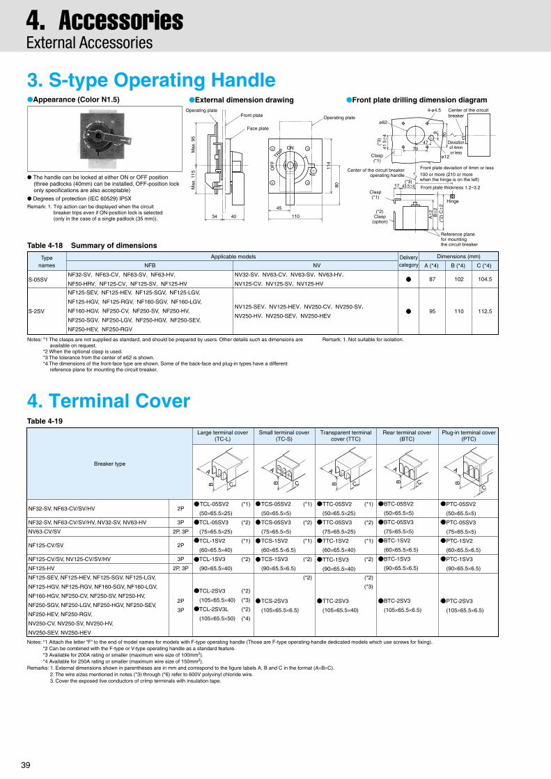
39
4. AccessoriesExternal Accessories
3. S-type Operating Handle
Table 4-18 Summary of dimensions
●Appearance (Color N1.5)
Notes: *1 The clasps are not supplied as standard, and should be prepared by users. Other details such as dimensions are available on request.
*2 When the optional clasp is used.*3 The tolerance from the center of ø62 is shown.*4 The dimensions of the front-face type are shown. Some of the back-face and plug-in types have a different
reference plane for mounting the circuit breaker.
Remark: 1. Not suitable for isolation.
Dimensions (mm)
S-05SV
S-2SV
Typenames
NF32-SV, NF63-CV, NF63-SV, NF63-HV,
NF50-HRV, NF125-CV, NF125-SV, NF125-HV
NF125-SEV, NF125-HEV, NF125-SGV, NF125-LGV,
NF125-HGV, NF125-RGV, NF160-SGV, NF160-LGV,
NF160-HGV, NF250-CV, NF250-SV, NF250-HV,
NF250-SGV, NF250-LGV, NF250-HGV, NF250-SEV,
NF250-HEV, NF250-RGV
NFB NV
Applicable models
NV32-SV, NV63-CV, NV63-SV, NV63-HV,
NV125-CV, NV125-SV, NV125-HV
NV125-SEV, NV125-HEV, NV250-CV, NV250-SV,
NV250-HV, NV250-SEV, NV250-HEV
Deliverycategory A (*4) C (*4)B (*4)
87 104.5102
95 112.5110
4. Terminal CoverTable 4-19
Notes: *1 Attach the letter “F” to the end of model names for models with F-type operating handle (Those are F-type operating-handle dedicated models which use screws for fixing).*2 Can be combined with the F-type or V-type operating handle as a standard feature.*3 Available for 200A rating or smaller (maximum wire size of 100mm2).*4 Available for 250A rating or smaller (maximum wire size of 150mm2).
Remarks: 1. External dimensions shown in parentheses are in mm and correspond to the figure labels A, B and C in the format (A×B×C).2. The wire sizes mentioned in notes (*3) through (*6) refer to 600V polyvinyl chloride wire.3. Cover the exposed live conductors of crimp terminals with insulation tape.
Breaker typeA
B C
A
B C
A
B C
A
B C
A
B
C
NF32-SV, NF63-CV/SV/HV
NF32-SV, NF63-CV/SV/HV, NV32-SV, NV63-HV
NV63-CV/SV
NF125-CV/SV
NF125-CV/SV, NV125-CV/SV/HV
NF125-HV
NF125-SEV, NF125-HEV, NF125-SGV, NF125-LGV,
NF125-HGV, NF125-RGV, NF160-SGV, NF160-LGV,
NF160-HGV, NF250-CV, NF250-SV, NF250-HV,
NF250-SGV, NF250-LGV, NF250-HGV, NF250-SEV,
NF250-HEV, NF250-RGV,
NV250-CV, NV250-SV, NV250-HV,
NV250-SEV, NV250-HEV
2P
3P
2P, 3P
2P
3P
2P, 3P
2P
3P
TCL-05SV2 (*1)
(50×65.5×25)
TCL-05SV3 (*2)
(75×65.5×25)
TCL-1SV2 (*1)
(60×65.5×40)
TCL-1SV3 (*2)
(90×65.5×40)
TCL-2SV3 (*2)
(105×65.5×40) (*3)
TCL-2SV3L (*2)
(105×65.5×50) (*4)
TCS-05SV2 (*1)
(50×65.5×5)
TCS-05SV3 (*2)
(75×65.5×5)
TCS-1SV2 (*1)
(60×65.5×6.5)
TCS-1SV3 (*2)
(90×65.5×6.5)
(*2)
TCS-2SV3
(105×65.5×6.5)
TTC-05SV2 (*1)
(50×65.5×25)
TTC-05SV3 (*2)
(75×65.5×25)
TTC-1SV2 (*1)
(60×65.5×40)
TTC-1SV3 (*2)
(90×65.5×40)
(*2)
TTC-2SV3
(105×65.5×40)
BTC-05SV2
(50×65.5×5)
BTC-05SV3
(75×65.5×5)
BTC-1SV2
(60×65.5×6.5)
BTC-1SV3
(90×65.5×6.5)
BTC-2SV3
(105×65.5×6.5)
PTC-05SV2
(50×65.5×5)
PTC-05SV3
(75×65.5×5)
PTC-1SV2
(60×65.5×6.5)
PTC-1SV3
(90×65.5×6.5)
PTC-2SV3
(105×65.5×6.5)
(*3)
Large terminal cover(TC-L)
Small terminal cover(TC-S)
Transparent terminalcover (TTC)
Rear terminal cover(BTC)
Plug-in terminal cover(PTC)
●External dimension drawing ●Front plate drilling dimension diagram
Operating plate
ON
OF
F
TRIP
45
110
114
80
Operating plateFront plate
Max
. 95
Max
. 115
34 40
Face plateø62
4-ø4.5 Center of the circuitbreaker
Deviationof 4mmor less
9
70
4770
Clasp(*1)
Clasp(*1)
(*2)Clasp
(option)
(*3)
41.5
±4
(*3)43.5±4
Center of the circuit breakeroperating handle
17
Front plate deviation of 4mm or less100 or more (210 or more when the hinge is on the left)
Hinge
A±2 B±2
(*2)
C±2
Reference plane for mountingthe circuit breaker
ø12
Front plate thickness 1.2–3.2
● The handle can be locked at either ON or OFF position (three padlocks (40mm) can be installed, OFF-position lock only specifications are also acceptable)
● Degrees of protection (IEC 60529) IP5XRemark: 1. Trip action can be displayed when the circuit
breaker trips even if ON-position lock is selected(only in the case of a single padlock (35 mm)).
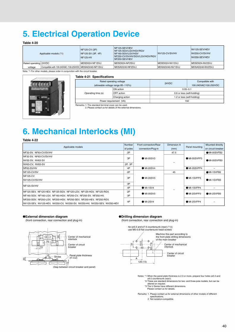
40
Remarks: 1. The standard terminal cover can be used.2. Please contact us for details of the external dimensions.
Note: *1 For other models, please order in conjunction with the circuit breaker.
5. Electrical Operation DeviceTable 4-20
Table 4-21 Specifications
24VDC
Compatible with 100-240VAC /100-250VDC
NF125-CV (3P)
NF125-SV (3P, 4P)
NF125-HV
MDSD024-NF1SVJ
MDSAD240-NF1SVJ
NV125-CV/SV/HV
MDSD024-NV1SVJ
MDSAD240-NV1SVJ
NV125-SEV/HEV
NV250-CV/SV/HV
NV250-SEV/HEV
MDSD024-NV2SVJ
MDSAD240-NV2SVJ
Compatible with
100-240VAC/100-250VDC24VDC
0.05–0.1
0.6 or less (self-holding)
1.2 or less (self-holding)
150
ON action
OFF action
Charging action
Operating time (s)
Rated operating voltage
(allowable voltage range 85~110%)
Power requirement (VA)
Rated operating
voltage
Applicable models (*1)
NF125-SEV/HEVNF125-SGV/LGV/HGV/RGVNF160-SGV/LGV/HGVNF250-CV/SV/HV/SGV/LGV/HGV/RGVNF250-SEV/HEV
MDSD024-NF2SVJ
MDSAD240-NF2SVJ
6. Mechanical Interlocks (MI)Table 4-22
Notes: *1 When the panel plate thickness is 2.3 or more, prepare four holes (ø5.5 and ø9.5 countersunk (rear)).
*2 These are standard dimensions for two- and three-pole models, but can be altered on request.
*3 The U Series have different dimensions. Please contact us for details.
Remarks: 1. Please contact us for external dimensions of other models of different specifications.
2. Not isolation-compatible.
Applicable models
NF32-SV, NF63-CV/SV/HV
NF32-SV, NF63-CV/SV/HV
NV32-SV, NV63-SV
NV63-CV, NV63-SV
NF63-SV/HV
NF125-CV/SV
NF125-CV
NV125-CV/SV/HV
NF125-SV/HV
NF125-SEV, NF125-HEV, NF125-SGV, NF125-LGV, NF125-HGV, NF125-RGV,
NF160-SGV, NF160-LGV, NF160-HGV, NF250-CV, NF250-SV, NF250-HV,
NF250-SGV, NF250-LGV, NF250-HGV, NF250-SEV, NF250-HEV, NF250-RGV,
NV125-SEV, NV125-HEV, NV250-CV, NV250-SV, NV250-HV, NV250-SEV, NV250-HEV
Number
of poles
2P
3P
2P, 3P
4P
2P
3P
3P
4P
2P
3P
4P
Front connection/Rear
connection/Plug-in
MI-05SV3
MI-05SV4
MI-05SV3
MI-1SV4
MI-05SV3
MI-2SV4
Dimension A
(mm)
47.5
–
45
–
Panel mounting
MI-05SVFP3
MI-05SVFP4
MI-1SVFP3
MI-1SVFP4
MI-2SVFP3
MI-2SVFP4
Mounted directly
on circuit breaker
MI-05SVFB2
MI-05SVFB3
–
MI-1SVFB2
MI-1SVFB3
–
MI-2SVFB3
–
●External dimension diagram (front connection, rear connection and plug-in)
●Drilling dimension diagram (front connection, rear connection and plug-in)
Panel plate thickness(t1-3.2)
(Gap between circuit breaker and panel)
15Stroke
Center of circuit breaker
Center of mechanical interlock
Center of circuit breaker
Center of mechanical interlock
Machine this part according to the front plate drilling dimensions of the main breaker
4ø (ø5.5 and ø7.5 countersunk (rear) (*1)); use M5×0.8 flat countersunk head screws
1.5
33
70
50
120 (*2)A
22
31 15.5
44
13
63 (
*3)

41
4. AccessoriesExternal Accessories
8. IEC 35mm Rail Mounting AdaptersTable 4-24
7. Handle Lock Devices and Card HolderTable 4-23
Notes: *1 HLF types are used for OFF-lock, and HLN types for ON-lock.*2 HL-S types are used for OFF-lock.
Remark: 1. Users are requested to prepare padlocks for HL and HL-S types (25mm padlock for HL, and 35mm padlock for HL-S).
35Applicable models
NF32-SV, NF63-CV/SV/HV, NV32-SV, NV63-CV/SV/HV
Number of poles
2P, 3P
Type names
DIN-05SV
Image
3.5
Mounting hook for IEC 35mm rail.
9. Insulating Barrier
NF32-SV, NF63-CV/SV/HV
NV63-CV
NF32-SV, NF63-CV/SV/HV,
NV32-SV, NV63-SV/HV
NF125-CV/SV
NF125-CV/SV,
NV125-CV/SV/HV
NF125-HV
NF125-SEV, NF125-HEV, NF125-SGV, NF125-LGV, NF125-HGV,
NF125-RGV, NF160-SGV, NF160-LGV, NF160-HGV, NF250-CV,
NF250-SV, NF250-HV, NF250-SGV, NF250-LGV, NF250-HGV,
NF250-SEV, NF250-HEV, NF250-RGV,
NV125-SEV, NV125-HEV, NV250-CV, NV250-SV, NV250-HV,
NV250-SEV, NV250-HEV
2P
2P, 3P
3P
4P
2P
3P
4P
2P, 3P
2P
3P
4P
LC-05SV
LC-05SV
LC-05SV
(*1)
HLF-05SV
HLN-05SV
(*1)
HLF-05SV
HLN-05SV
(*1)
HLF-05SV
HLN-05SV
HLS-05SV2
HLS-05SV
HLS-05SV2
HLS-05SV
HLS-2SV
CH-P No.5
Lock cover (LC) Handle lock (HL) Handle lock (HL-S) (*2) Card holder
The insulating barrier enhances the insulation between the phases of circuit breaker terminals. It also prevents accidents due to conductive foreign matter and dust, and secondary accidents when isolating a fault current.
Applicable models Connection methodFront connection
( “ ” denotes optional)
Standardattachment
Standardattachment
–
–
–
–
–
Standardattachment
Rear connection Plug-inNFB NV
Remark: 1. Always mount the insulating barrier when it comes with the circuit breaker.
NF32-SV, NF63-CV, NF125-CV
NF63-SV/HV, NF125-SV/HV
NV32-SV, NV63-CV, NV125-CV
NF125-SEV/HEVNF125-RV, NF250-CV/SV/HV/SEV/HEV
NV63-SV/HVNV125-SV/HV
NV125-SEV/HEVNV250-CV/SV/HV/SEV/HEV
(1) The insulating barrier is available for the models listed in the table below.
Table 4-25

42
●Insulating Barrier - Front (BA-F)Table 4-26 Summary of dimensions
●Insulating Barrier - Plug-in (BA-P)Table 4-27 Summary of dimensions
Applicable models Dimensions (mm) Quantity per breakerType names Delivery
category Reference diagramA B 2P 3P 4PNFB NV
BAF-05SV
BAF-2SV
Note: *1 Not supplied with NV.
A
B
50
100
59.5
59.5
1(*1)
2
2
4
3
6
NF32-SV, NF63-CV, NF125-CV
NF63-SV/HV, NF125-SV/HV
NF125-SEV, NF125-HEV, NF125-SGV, NF125-LGV, NF125-HGV, NF125-RGV, NF160-SGV, NF160-LGV, NF160-HGV, NF250-CV, NF250-SV, NF250-HV, NF250-SGV, NF250-LGV, NF250-HGV, NF250-SEV, NF250-HEV, NF250-RGV
NV32-SVNV63-CVNV125-CV
NV63-SV/HVNV125-SV/HV
NV125-SEV/HEVNV250-CV/SV/HV/SEV/HEV
Applicable models Dimensions (mm) Quantity per breakerType name Delivery
category Reference diagramA B 2P 3P 4PNFB NV
NF125-SEV, NF125-HEV,
NF125-SGV, NF125-LGV,
NF125-HGV, NF125-RGV,
NF160-SGV, NF160-LGV,
NF160-HGV, NF250-CV,
NF250-SV, NF250-HV,
NF250-SGV,
NF250-LGV, NF250-HGV,
NF250-SEV, NF250-HEV,
NF250-RGV
NV125-SEV/HEV
NV250-CV/SV/HV/SEV/HEVBAP-2SV
Standardattachment 172 74.5 4 4 6
B
A
Standardattachment
Standardattachment

43
Operating Characteristics
Operating characteristicsNF32-SV 3A~6ANF63-CV 3A~6ANF63-SV 3A~6A
Max.
Min.
Instantaneous tripTime-delay trip
× 100% of rated current
AC
DC
4h
2h
1h
30min20min
10min14min
6min4min
2min
1min
30s20s
10s
5s
2s
1s
0.5s
0.2s
0.1s
0.05s
0.02s
0.01s
Ope
ratin
g tim
e
Ope
ratin
g tim
e
Min.
Max.
Time-delay trip Instantaneous trip
4h
2h
1h
30min20min
10min14min
6min4min
2min
1min
30s20s
10s
5s
2s
1s
0.5s
0.2s
0.1s
0.05s
0.02s
0.01s
× 100% of rated current
DC
AC
Operating characteristicsNF32-SV 10A~32ANF63-CV 10A~32ANF63-SV 10A~32ANF63-HV 10A~32A
DC
AC
× 100% of rated current
Min.
Max. (40A~50A)
Max. (60A~63A)
Operating characteristicsNF63-CV 40A~63ANF63-SV 40A~63ANF63-HV 40A~63A
Time-delay trip Instantaneous trip
Ope
ratin
g tim
e
10min14min20min30min
1h
2h
4h
6min4min
2min
1min
2s
1s
0.5s
0.2s
0.1s
0.05s
0.02s
0.01s
5s
10s
20s30s
Instantaneous trip current is fixed to AC600A±120A and DC850A±170A.
4020151065 7 3042 31 1.254020151065 7 3042 31 1.25 40 50 60 70 10020151065 7 3042 31 1.25
Internal Accessories
AL AXLead-wire direction
Right-side mountingLeft-side mounting
Operating handle SHT or UVT
2-pole
3, 4-pole
Ambient Compensating Curve
Rat
ed a
mbi
ent
tem
pera
ture
(Rated ambienttemperature 40°C) –10
130
120
110
100
90
80
Cur
rent
rat
ing
(%)
Ambient temperature (°C)
6050403020100
External AccessoriesAccessories Accessories
F
V
S
IEC 35mm rail mounting adapters
MI
TC-S
TC-L
TTC
BTC
PTC
Type nameF-05SV2F-05SVV-05SV2V-05SVS-05SV
Type nameMI-05SV3MI-05SV4TCS-05SV2TCS-05SV3TCL-05SV2TCL-05SV2LTCL-05SV3TCL-05SV3LTCL-05SV4TTC-05SV2TTC-05SV3BTC-05SV2BTC-05SV3PTC-05SV2PTC-05SV3DIN-05SV
2P3, 4P2P3, 4P
Operating handle
Note: *1 HLF types are used for OFF-lock and HLN types for ON-lock.
Mechanical interlock 2, 3P4P2P3P
2P
3P
4P2P3P2P3P2P3P
Handle lock device
LC(*1)
HLHL-S
LC-05SVHLF-05SVHLN-05SVHLS-05SV
41
Reference page
37
38
39
Reference page
40
39
41
Small
Large
Skeleton
Rear
Plug-in
Terminal
cover
Rated current In (A)
690V500V440V415V400V380V230V
250V (*1)
AC
DC
IEC 60947-2(Icu/Ics)
3 4 (5) 6 10(15) 16 20 25
(30) 32
600–
2.5/2.52.5/2.52.5/2.5
5/55/5
7.5/7.52.5/2.5
32 32
NF32-SV
600–
2.5/2.52.5/2.52.5/2.5
5/55/5
7.5/7.52.5/2.5
3 4 (5) 6 10 (15)16 20 25 (30) 32
40 50 (60) 63
NF63-CV3 4 (5) 6 10 (15)16 20 25 (30) 32
40 50 (60) 63
NF63-SV
2600
–7.5/7.57.5/7.57.5/7.57.5/7.57.5/7.515/157.5/7.5
43 2 43
10 (15) 16 20 25(30) 32 40 50
(60) 63
NF63-HV
6902.5/2.57.5/7.5
10/810/810/810/825/197.5/7.5
Number of polesRated insulation voltage Ui (V)
Type name
Standard attached parts (front connection)
Ratedshort-circuitbreakingcapacity(kA)
Mounting screw: M4×0.7×55 (2 and 3P: 2pcs, 4P: 4pcs)Insulation barrier: (2P: 1pc, 3P: 2pcs, 4P: 3pcs) (*2)
Notes: *1 Use two poles for three- and four-pole products. Not available for use with connection as shown at the bottom of page 13.*2 Supplied with NF63-SV and NF63-HV.
NF32-SVNF63-CVNF63-SVNF63-HV
NF63-SV
5. Characteristics and DimensionsMolded-case Circuit Breakers

44
8
2-pole 3-pole 4-pole
Front connection
Rear connection
112
Mounting hole
22
25
50
50
75
25
75
100
5013
0
Trip button
45
5084
24
61
68
72
90
Insulation barrier(removable)
Neutral pole
4
ø8.
5
ø4.
5
Drilling plan
3-pole 4-pole2-pole
2525
Breaker
M4×0.7 taps or ø5
111
Drilling plan
3-pole 4-pole2-pole
Breaker
M4×0.7 taps or ø5
M4×0.7 breakermounting screw
8
50
4268
72
8
112
M6 screw
112
111
25
25
75
25
5025
50
22.5
70
52R1
2-pole
3-pole
4-pole
ø14
Breaker
Front-panel cutout
1.0mm clearance on each sideof the handle frame
Drilling plan
3-pole 4-pole
2-pole 2-pole 3-pole 4-pole
21
3089
11
7
5480
54
5483.5
85
170
116
5.5
ø6.5
M6 screw
80
50
105
75
25
25
5557 82
25 50
107
Details ofterminal
Plug-in
Plug-interminal block
Mountingplate
M5×0.8Terminal block mounting screw
ø6 holeor M5×0.8 taps
Breaker (plug-in terminal block)
Remark: 1. Only two- and three-pole models are available for NF32-SV and NF63-CV.
ø5.5(ø8.5 for 60A and 63A)
M5×0.8 screw(M8 for 60A and 63A)
12.5 max.
(16 max. for 60A and 63A)
(Conductor thickness t = 5 max.)
Conductor drilling for direct connection
42 (44 for 60A and 63A)
Mounting plate t = 3.2 max. Insulation tube
27 min.
27 min.
(31 min. for 60A and 63A)
(29 min. for 60A and 63A)
(46 for 60A and 63A)
16.5 max.
Conductor drilling
Applicable wire size: ø1.6 to 22mm2
(for M5×0.8 screw)

NF125-SV
45
Operating Characteristics
Min.
Max.
Time-delay trip Instantaneous trip
AC
DC
× 100% of rated current
4h
2h
1h
30min20min14min10min6min4min
2min
30s
1min
20s
10s
5s
2s
1s
0.5s
0.2s
0.1s
0.05s
0.02s
0.01s
Ope
ratin
g tim
e
Operating characteristicsNF125-SV 15A~32ANF125-HV 15A~32A
DC
AC
× 100% of rated current
Min.
Max. (40A~50A)
Max. (60A~100A)
Operating characteristicsNF125-CV 50A~100ANF125-SV 40A~100ANF125-HV 40A~100A
Time-delay trip Instantaneous trip
Ope
ratin
g tim
e
10min14min20min30min
1h
2h
4h
6min4min
2min
1min
2s
1s
0.5s
0.2s
0.1s
0.05s
0.02s
0.01s
5s
10s
20s30s
10min14min20min30min
1h
2h
4h
6min4min
2min
1min
2s
1s
0.5s
0.2s
0.1s
0.05s
0.02s
0.01s
5s
10s
20s30s
Min.
Max.
AC
DC
Time-delay trip Instantaneous trip
Operating characteristicsNF125-CV 125ANF125-SV 125ANF125-HV 125A
× 100% of rated current
Ope
ratin
g tim
eInstantaneous trip current is fixed to AC600A±120A and DC850A±170A.
4020151065 7 3042 31 1.2540 50 607020151065 7 3042 31 1.25 4020151065 7 3042 31 1.25
Internal Accessories
AL AXLead-wire direction
Right-side mountingLeft-side mounting
Operating handle SHT or UVT
2-pole
3, 4-pole
Ambient Compensating Curve
Rat
ed a
mbi
ent
tem
pera
ture
(Rated ambienttemperature 40°C) –10
130
120
110
100
90
80
Cur
rent
rat
ing
(%)
Ambient temperature (°C)
6050403020100
External AccessoriesAccessories Accessories
F
V
S
Electrical operation device
MI
TC-S
TC-L
TTC
BTC
PTC
Type name Type nameMI-05SV3MI-05SV4TCS-1SV2TCS-1SV3TCL-1SV2TCL-1SV3TCL-1SV4TTC-1SV2TTC-1SV3BTC-1SV2BTC-1SV3PTC-1SV2PTC-1SV3(*2)
2P3, 4P2P3, 4P
Operating handle
Notes: *1 HLF types are used for OFF-lock and HLN types for ON-lock.*2 Specify the working voltage. Refer to the reference page for type name.*3 Available for NF125-CV/SV.
Mechanical interlock 2, 3P4P2P3P2P3P4P2P3P2P3P2P3P
Handle lock device
LC(*1)
HLHL-S
LC-05SVHLF-05SVHLN-05SVHLS-1SV
41
Reference page
37
38
39
Reference page
40
Small
Large
Skeleton
Rear
Plug-in
Terminal
cover
F-1SV2F-1SVV-1SV2V-1SVS-05SV
39
40
Rated current In (A)
690V500V440V415V400V380V230V
250V (*1)
AC
DC
IEC 60947-2(Icu/Ics)
32600
–7.5/410/510/510/510/530/157.5/4
50 (60) 63 (75) 80 100 125
NF125-CV(15) 16 20 (30) 32 40 50 (60) 63 (75)
80 100 125
NF125-SV
26908/8
18/1825/2530/3030/3030/3050/5040/40
43 2 43
(15) 16 20 (30) 32 40 50 (60) 63 (75)
80 100 125
NF125-HV
69010/830/2350/3850/3850/3850/38100/75
–
Number of polesRated insulation voltage Ui (V)
Type name
Standard attached parts (front connection)
Ratedshort-circuitbreakingcapacity(kA)
Mounting screw: M4×0.7×55 (2 and 3P: 2pcs, 4P: 4pcs)(*2) Insulation barrier: (2P: 1pc, 3P: 2pcs, 4P: 3pcs)
Notes: *1 Use two poles for three- and four-pole products.If wired as shown at the bottom on page 13, three and four poles can be used for up to 400 and 500VDC, respectively.
*2 Supplied with NF125-SV and NF125-HV.
NF125-CVNF125-SVNF125-HV
5. Characteristics and DimensionsMolded-case Circuit Breakers

46
Front connection
Rear connection
Plug-in
Remarks: 1. The two-pole models of NF125-HV are three-pole models with the central pole removed.2. Only two- and three-pole models are available for NF125-CV.
50
24
68
61
45
724
90
60
30
90
60
22 30
90
12011
2
130
84 50
Mounting hole
Tripbutton
M8 screw
ø8.
5
ø8.5ø4.
5
Insulation barrier(removable)
Neutral pole
3-pole 4-pole2-pole
2-pole 3-pole 4-pole
Breaker
111
30
8
30
Drilling plan
M4×0.7 taps or ø5
Stud can berotated 90°
8
R1R1
30
90
28
90
30
102
52
72
68
8.5
2.5
15
54.5
104.5
15
2.5
16
112
60
5
30 57 86
52
60
30
3-pole2-pole
4-pole
3-pole
2-pole
4-pole
111
112
ø18
M4×0.7 taps or ø5
M4×0.7 breakermounting screw
3-pole2-pole 4-pole
Breaker
Drilling plan
Conductor drilling
Front-panel cutoutDrilling plan
1.0mm clearance on each sideof the handle frame
Breaker
Insulationtube
3-pole2-pole
2-pole
4-pole
4-pole3-pole
5.5
83.5
170
12
3089
21
11
54 8056
56
67 97 127
60
95
30
65
116
30
90
125
20 max.
M8 screwø8.5
Breaker (plug-in terminal block)
ø6 holeor M5×0.8 taps
Plug-interminal block
Mountingplate
Details ofterminal
85
15 connection allowance
M8 bolt
(Conductor thickness t = 5 max.)
19 max.
Comb conductor 16.5 max.
Conductor drilling for direct connection
Mounting plate t = 3.2 max.
Insulation tube
M5×0.8 Terminal block mounting nut or screw mounted directly
Solderless terminalfor wire size
14~2/0AWG CU/AL
Wire connection

47
Operating Characteristics
Max.
Min.
Time-delay trip Instantaneous trip
Operating characteristicsNF250-CV 100A~225ANF250-SV 100A~225ANF250-HV 125A~225A
DC
AC
× 100% of rated current
4h
2h
1h
30min20min14min10min6min4min
2min
30s
1min
20s
10s
5s
2s
1s
0.5s
0.2s
0.1s
0.05s
0.02s
0.01s
Ope
ratin
g tim
e
Operating characteristicsNF250-CV 250ANF250-SV 250ANF250-HV 250A
Time-delay trip Instantaneous trip
Min.
Max.
AC
DC
4h
2h
1h
30min20min14min10min6min4min
2min
30s
1min
20s
10s
5s
2s
1s
0.5s
0.2s
0.1s
0.05s
0.02s
0.01s
Ope
ratin
g tim
e
× 100% of rated current
4020151065 7 3042 31 1.254020151065 7 3042 31 1.25
Internal Accessories
AL AXLead-wire direction
Right-side mountingLeft-side mounting
Operating handle SHT or UVT
Ambient Compensating Curve
(Rated ambienttemperature 40°C) –10
Ambient temperature (°C)
6050403020100
130
120
110
100
90
80
Cur
rent
rat
ing
(%)
Rat
ed a
mbi
ent
tem
pera
ture
External AccessoriesAccessories Accessories
Electrical operation device
MI
TC-S
TC-L
TTCBTCPTC
Type name Type nameMI-05SV3MI-2SV4TCS-2SV3TCL-2SV3TCL-2SV3LTCL-2SV4TTC-2SV3BTC-2SV3PTC-2SV3(*2)
Notes: *1 HLF types are used for OFF-lock and HLN types for ON-lock.*2 Specify the working voltage. Refer to the reference page for type name.*3 Available for NF250-CV/SV.
Mechanical interlock2, 3P4P
2, 3P
2, 3P
4P2, 3P2, 3P2, 3P
Handle lock device
LC(*1)
HLHL-S
LC-05SVHLF-05SVHLN-05SVHLS-2SV
Reference page Reference page
40
Small
Large
SkeletonRearPlug-in
Terminal
cover
F-2SVV-2SVS-2SV
373839
4139
40
FVS
Operating handle
Rated current In (A)
690V500V440V415V400V380V230V250V
AC
DC (*1)
IEC 60947-2(Icu/Ics)
32600
–10/815/1225/1925/1925/1936/2715/12
(*1) (100)125 150 175 200
225 250
NF250-CV(*1) (100)
125 150 160 175200 225 250
NF250-SV
26908/8
30/3036/3636/3636/3636/3685/85
20/20 (300V)
43 2 43
125 150 160 175200 225 250
NF250-HV
69010/850/3865/6570/7075/7575/75
100/10040/40 (300V)
Number of polesRated insulation voltage Ui (V)
Type name
Standard attached parts (front connection)
Ratedshort-circuitbreakingcapacity(kA)
Mounting screw: M4×0.7×55 (2 and 3P: 2pcs, 4P: 4pcs)Insulation barrier: (2P: 2pcs, 3P: 4pcs, 4P: 6pcs)
Note: *1 Use two poles for three- and four-pole products. In this case, do not use the neutral pole of the four-pole products.If wired as shown at the bottom of page 13, three-pole NF250-CV can be used for up to 400VDC, three-pole NF250-SV and NF250-HV up to 500VDand four-pole products up to 600VDC.
NF250-SV
NF250-CVNF250-SVNF250-HV
5. Characteristics and DimensionsMolded-case Circuit Breakers

48
Front connection
Rear connection
Plug-in
10510
2
50
61
68
45
724
92
24
70
2235 35
126
140
105
35
100
100
165
144
C1
C1
109
Mounting hole
Trip button
ø4.
5
ø8.
5
ø8.5
ø8.5
3-pole 4-pole
3-pole 4-pole
Neutral pole
Insulation barrier(removable)
M8 bolt(hex-socket)
M4×0.7 taps or ø5
Breaker
Breaker Breaker
Drilling plan
32.5
52
100
4-pole
3-pole
70
35
105
35
126
144
35ø24
4-pole3-pole
15
15
22 20
144
68
72
71
106
4-pole
3-pole
6
105
70
8
M4×0.7 taps or ø5
M4×0.7 breakermounting screw
Drilling plan
1.0mm clearance on each sideof the handle frame
Front-panel cutout
Drilling plan
Stud can berotated 90°
Connection allowance
Mountingplate
Plug-interminal block
89
112
190
165
21
30
31
144
34.5
28 20
1516
11
70
15
24
56.5
56.5
142
10570
107
8054
4-pole3-pole
ø6 holeor M5×0.8 taps
Breaker (plug-in terminal block)
ø9M8 bolt
ø9M8 bolt
Insulationtube
Connection allowance
M5terminal block mounting screw Insulation
barrier
3-pole 70
4-pole 105
3-pole 105
4-pole 140
4-pole 145
3-pole 110
Stud attachable in thisdirection only
R1
Conductor drilling for direct connection
30
125200
175A 14 95mm2
250A 70 125mm2
Wire connection
Solderless terminalfor wire size
Insulation tube
Mounting plate t = 3.2 max.
25 max.
Or
25 max.
(Conductor thickness t = 7 max.)
Remarks: 1. two-pole models are three-pole models with the central pole removed.2. Only two- and three-pole models are available for NF250-CV.

49
5. Characteristics and DimensionsMolded-case Circuit Breakers
NF125-SGVNF250-SGVNF160-LGVNF125-HGVNF250-HGVNF250-RGV
NF160-SGVNF125-LGVNF250-LGVNF160-HGVNF125-RGV
Rat
ed s
hort
-circ
uit
brea
king
cap
acity
(kA
)
Rated current In (A)
Number of poles
IEC60947-2(Icu/Ics)
AC
DC (*1)
Rated insulation voltage Ui (V)
Type name
690V
500V
440V
415V
400V
380V
230V
200V
300V
NF160-LGV
690
8/8
30/30
36/36
36/36
36/36
36/36
85/85
85/85
20/20
NF125-SGV
16-20, 20-25, 25-32 32-40, 35-50, 45-63
56-80, 70-100, 90-125
2 3 4
690
8/8
30/30
36/36
36/36
36/36
36/36
85/85
85/85
20/20
125-160
2 3 4
690
8/8
30/30
36/36
36/36
36/36
36/36
85/85
85/85
20/20
2 3 4
690
8/8
36/36
50/50
50/50
50/50
50/50
90/90
90/90
20/20
125-160
2 3 4
NF250-LGV
690
8/8
36/36
50/50
50/50
50/50
50/50
90/90
90/90
20/20
125-160140-200175-250
2 3 44
690
8/8
36/36
50/50
50/50
50/50
50/50
90/90
90/90
20/20
16-20, 20-25, 25-32 32-40, 35-50, 45-63
56-80, 70-100, 90-125
2 3
NF250-SGVNF160-SGV NF125-LGV
Operating CharacteristicsNote: *1 When wired as shown at the bottom of page 13, three-pole models can be used for up to 500VDC, and 4-pole models for up to 600VDC.
NF250-SGV
Mounting screw: M4×0.7×55 (2 and 3P: 2pcs, 4P: 4pcs)Insulation barrier: (2P: 2pcs, 3P: 4pcs, 4P: 6pcs)
Rat
ed s
hort
-circ
uit
brea
king
cap
acity
(kA
)
Rated current In (A)
Number of poles
IEC60947-2(Icu/Ics)
AC
DC (*1)
Rated insulation voltage Ui (V)
Type name
690V
500V
440V
415V
400V
380V
230V
200V
300V
2 3 4 2 3 4 2 3 4 2 3 2 3
690
10/8
50/38
65/65
70/70
75/75
75/75
100/100
100/100
40/40
16-20, 20-25, 25-3232-40, 35-50, 45-63
56-80, 70-100, 90-125
690
10/8
50/38
65/65
70/70
75/75
75/75
100/100
100/100
40/40
125-160
690
10/8
50/38
65/65
70/70
75/75
75/75
100/100
100/100
40/40
NF160-HGVNF125-HGV
690
–
–
125/125
150/150
150/150
150/150
150/150
150/150
–
16-20, 20-25, 25-3232-40, 40-50, 50-63
63-80, 80-100, 100-125
690
–
–
125/125
150/150
150/150
150/150
150/150
150/150
–
125-160160-200200-250
NF250-RGVNF125-RGVNF250-HGV
Standard attached parts(front connection)
Mounting screw: M4×0.7×55 (2 and 3P: 2pcs, 4P: 4pcs)Insulation barrier: (2P: 2pcs, 3P: 4pcs, 4P: 6pcs)
Standard attached parts(front connection)
Internal Accessories
External Accessories
Ambient Compensating Curve
AL AXLeft-sidemounting
Right-sidemounting
Operating handle
SHT or UVT Lead-wire direction
Remark: 1. Refer to page 34.
Accessories Accessories
Electrical operation device
MI
TC-S
TC-L
TTCBTCPTC
Type name Type nameMI-05SV3MI-2SV4TCS-2SV3TCL-2SV3TCL-2SV3LTCL-2SV4TTC-2SV3BTC-2SV3PTC-2SV3(*2)
Notes: *1 HLF types are used for OFF-lock and HLN types for ON-lock.*2 Specify the working voltage. Refer to the reference page for type name.*3 Available for NF250-CV/SV.
Mechanical interlock2, 3P4P
2, 3P
2, 3P
4P2, 3P2, 3P2, 3P
Handle lock device
LC(*1)
HLHL-S
LC-05SVHLF-05SVHLN-05SVHLS-2SV
Reference page Reference page
40
Small
Large
SkeletonRearPlug-in
Terminal
cover
F-2SVV-2SVS-2SV
373839
4139
40
FVS
Operating handle
125-160140-200175-250
125-160140-200175-250
-10
Cur
rent
rat
ing
(%)
Rat
ed a
mbi
ent
tem
pera
ture
Ambient temperature (°C)(rated ambient temperature 40°C)
605040302010080
90
100
110
120
130
DC
NF125-SGV NF125-LGV NF125-HGV NF125-RGV Current setting Ir = 16-20A(Rated current In=20A) Current setting Ir = 20-25A(Rated current In=25A) Current setting Ir = 25-32A(Rated current In=32A)
600A ± 120A 850A ± 170AAC DC
lnstantaneous tripcurrent
Operating Characteristics
Thermal-Adjustable types
time
AC
Max. totalbreaking
Time-delay trip Instantaneous trip
Current( × 100% of Ir)
Instantaneous tripping current( × 100% of In)
Ope
ratin
g tim
e
10min14min20min30min
1h
2h
4h
6min4min
2min
1min
2s
1s
0.5s
0.2s
0.1s
0.05s
0.02s
0.01s
5s
10s
20s30s
4020151065 7 3042 31 1.25 50 6070
Max.
Min.
DC
Max.
NF125-SGV NF125-LGV NF125-HGV Current setting Ir = 32-40A(Rated current In=40A) Current setting Ir = 35-50A(Rated current In=50A)NF125-RGV Current setting Ir = 32-40A(Rated current In=40A) Current setting Ir = 40-50A(Rated current In=50A)
Operating Characteristics
Thermal-Adjustable types
time
AC
Max. totalbreakingMin.
Time-delay trip Instantaneous trip
600A ± 120A 850A ± 170AAC DC
lnstantaneous tripcurrent
Current( × 100% of Ir)
Instantaneous tripping current( × 100% of In)
4020151065 7 3042 31 1.25
Ope
ratin
g tim
e
10min14min20min30min
1h
2h
4h
6min4min
2min
1min
2s
1s
0.5s
0.2s
0.1s
0.05s
0.02s
0.01s
5s
10s
20s30s
Current setting Ir = 45- 63A(Rated current In= 63A)Current setting Ir = 56- 80A(Rated current In= 80A)
NF125-SGV NF125-LGV NF125-HGV
NF125-RGV Current setting Ir = 50- 63A(Rated current In= 63A)Current setting Ir = 63- 80A(Rated current In= 80A)
Current( × 100% of Ir)
Instantaneous tripping current( × 100% of In)
1000 ± 200 1300 ± 260
lnstantaneous tripcurrent ratio
ACxln(%)
DCxln(%)
time
Max.
Max. totalbreaking
Min.
DC
AC
Time-delay trip Instantaneous trip
Operating Characteristic CurvesThermal-Adjustable types
4020151065 7 3042 31 1.25
Ope
ratin
g tim
e
10min14min20min30min
1h
2h
4h
6min4min
2min
1min
2s
1s
0.5s
0.2s
0.1s
0.05s
0.02s
0.01s
5s
10s
20s30s
1000 ± 200 1300 ± 260
lnstantaneous tripcurrent ratio
ACxln(%)
DCxln(%)
NF125-SGV NF125-LGV NF125-HGV Current setting Ir = 70-100A(Rated current In=100A) Current setting Ir = 90-125A(Rated current In=125A)NF160-SGV NF160-LGV NF160-HGV Current setting Ir = 125-160A(Rated current In=160A)NF250-SGV NF250-LGV NF250-HGV Current setting Ir = 125-160A(Rated current In=160A) Current setting Ir = 140-200A(Rated current In=200A) Current setting Ir = 175-250A(Rated current In=250A)NF125-RGV Current setting Ir = 80-100A(Rated current In=100A) Current setting Ir = 100-125A(Rated current In=125A)NF250-RGV Current setting Ir = 125-160A(Rated current In=160A) Current setting Ir = 160-200A(Rated current In=200A) Current setting Ir = 200-250A(Rated current In=250A)
time
Max.
Max. totalbreaking
Min.
DC
AC
Time-delay trip Instantaneous trip
Operating Characteristic CurvesThermal-Adjustable types
4020151065 7 3042 31 1.25
Ope
ratin
g tim
e
10min14min20min30min
1h
2h
4h
6min4min
2min
1min
2s
1s
0.5s
0.2s
0.1s
0.05s
0.02s
0.01s
5s
10s
20s30s
Current( × 100% of Ir)
Instantaneous tripping current( × 100% of In)

50
105
102
50
61
68
45
724
92
24
70
2235
ø4.
5
ø8.
5
35
126
140
105
35
100
100
165
144
Neutral pole
Breaker
M4×0.7 taps or ø5
3-pole 4-pole
Drilling plan
Mounting hole
Insulating barrier(removable)
Trip button
3-pole 4-pole
M8 bolt(hex-socket)
Conductor drilling for direct connection
15
15
22 20
144
70
35
ø24
68
72
71
106
4-pole
3-pole
8
6
105
70
105
35
126
144
Drilling plan
4-pole3-pole
M4×0.7 taps or ø5
Breaker
M4×0.7 breakermounting screw
Insulating tubeø9M8 bolt
Connection allowance
Insulating tube
Stud can berotated 90°Mounting plate
t max. = 3.2
32.5
52
100
4-pole
3-pole
Breaker
1mm clearance on each sideof the handle frame
Front-panel cutout
R1
89
112
190
165
21
30
31
144
34.5
28 20
3-pole 70
4-pole 105
3-pole 105
4-pole 140
1516
11
70
15
24 c
onne
ctio
n al
low
ance
56.5
56.5
142
105
4-pole
Stud attachable in thisdirection only
Insulating barrier
M5terminal block mounting screw
Mounting plate
Plug-interminal block
ø9M8 bolt
Drilling plan
Breaker (plug-in terminal block)
4-pole 145
3-pole 110
35
ø6mm holeor M5×0.8 taps
70
107
3-pole
8054
25 max.
Or
C1
C1
10
ø8.5
9
ø8.5
25 max.
(Conductor thickness t = 7 max.)
Remark: 1. Two-pole models are three-pole models with the central pole removed.
Front connection
Rear connection
Plug-in
30
125200
175A 14 95mm2
250A 70 125mm2
Wire connection
Solderless terminalfor wire size

51
Operating Characteristics
Internal Accessories
AL AXLead-wire direction
Right-side mountingLeft-side mounting
Operating handle
PAL
SHT or UVT
(Note)
Ambient Compensating Curve
The rated current does not have thermal characteristics. Reduce the current as shown in the curve on the left chart if the ambient temperature exceeds 40 °C.
Rat
ed a
mbi
ent
tem
pera
ture
–10
130
120
110
100
90
80
70
Der
atin
g of
load
cur
rent
(%
)
Ambient temperature (°C)
6050403020100
External AccessoriesAccessories Accessories
Electrical operation device
MI
TC-S
TC-L
TTCBTCPTC
Type name Type nameMI-05SV3MI-2SV4TCS-2SV3TCL-2SV3TCL-2SV3LTCL-2SV4TTC-2SV3BTC-2SV3PTC-2SV3(*2)
Operating handle
Notes: *1 HLF types are used for OFF-lock and HLN types for ON-lock.*2 Specify the working voltage. Refer to the reference page for type name.
Mechanical interlock3P4P3P
3P
4P3P3P3P
Handle lock device
LC(*1)
HLHL-S
LC-05SVHLF-05SVHLN-05SVHLS-2SV
Reference page Reference page
40
Small
Large
SkeletonRearPlug-in
Terminal
cover
F-2SVV-2SVS-2SV
373839
4139
40
FVS
Rated current In (A)
690V500V440V415V400V380V230V250V
AC
DC
IEC 60947-2(Icu/Ics)
436908/8
30/3036/3636/3636/3636/3685/85
–
16-32 32-6363-125
NF125-SEV
Number of polesRated insulation voltage Ui (V)
Type name
4369010/850/3865/6570/7075/7575/75
100/100–
16-32 32-6363-125
NF125-HEV
436908/8
30/3036/3636/3636/3636/3685/85
–
80-160125-250
NF250-SEV
4369010/850/3865/6570/7075/7575/75
100/100–
80-160125-250
NF250-HEV
Standard attached parts (front connection)
Ratedshort-circuitbreakingcapacity(kA)
Mounting screw: M4×0.7×55 (3P: 2pcs, 4P: 4pcs)Insulation barrier: (3P: 4pcs, 4P: 6pcs)
NF125-SEVNF125-HEVNF250-SEVNF250-HEV
NF125-SEV
LTD operating time TL
12–60–80–100s ±20%(at 200%)
LTD operating time at 125% (I6t ON)
670s (TL = 100s set)540s (TL = 80s set)400s (TL = 60s set)80s (TL = 12s set)
Operating characteristics
NF125-SEV NF125-HEV
Current setting Ir16-3232-6363-125
Rated current In32A63A125A
I6t ON
I6t OFF
I2t OFF
I2t ON 0.1±0.03s
0.2±0.04s0.3±0.06s
Max. total breaking timeINST pickup current IiIn × 2~14 ±15%, Ir × 14 ±15%
STD operating time Ts
STD pickup current IsIr × (2–2.5–3–3.5–4–5–6–7–8–10) ±15%
Ope
ratin
g tim
e
10h
5h
2h
1h
30min20min
10min14min
6min4min
2min
1min
30s20s
10s
5s
2s
1s
0.5s
0.2s
0.1s
0.05s
0.02s
0.01s1.251 32 4 3075 6 10 15 20 40
0.70.6
× 100% of current setting IrInstantaneous tripping current (% of rated current or % of current setting Ir)
1.251 32 4 3075 6 10 15 20 400.7
0.6
Ope
ratin
g tim
e
10h
5h
2h
1h
30min20min
10min14min
6min4min
2min
1min
30s20s
10s
5s
2s
1s
0.5s
0.2s
0.1s
0.05s
0.02s
0.01s
× 100% of current setting IrInstantaneous tripping current (% of rated current or % of current setting Ir)
0.1±0.03s
0.2±0.04s0.3±0.06s
Max. total breaking time
LTD operating time at 125% (I6t ON)
670s (TL = 100s set)540s (TL = 80s set)400s (TL = 60s set)80s (TL = 12s set)
I6t ON
I6t OFF
I2t OFF
I2t ON
INST pickup current IiIn × 2~14 ±15%, Ir × 14 ±15%
STD operating time Ts
STD pickup current IsIr × (2–2.5–3–3.5–4–5–6–7–8–10) ±15%
LTD operating time TL
12–60–80–100s ±20%(at 200%)
Operating characteristics
NF250-SEV NF250-HEV
Current setting Ir80-160125-250
Rated current In160A250A
5. Characteristics and DimensionsMolded-case Circuit Breakers

52
Front connection
Rear connection
Plug-in
105
102
50
61
68
45
724
92
24
70
22ø8.5 35
ø4.
5
ø8.
5
35
126
140
105
35
100
100
165
144
3-pole 4-pole
3-pole 4-pole
C1
C1
10
ø8.5
Mounting hole
Trip button
M8 bolt(hex-socket)
Drilling plan
Drilling plan
M4×0.7 taps or ø5
M4×0.7 taps or ø5
Drilling plan
Breaker
1.0mm clearance on each sideof the handle frame
Front-panel cutout
Breaker
Insulation barrier(removable)
Insulation barrier
Stud can berotated 90°
4-pole
3-pole
3-pole 4-pole
15
15
22 connection allowance 20
144
70
35
ø24
68
72
71
106
8
6
105
70
35
105
35
126
144
4-pole
3-poleBreaker
32.5
R1
52
100ø9M8 bolt
Neutral pole
M4×0.7 breakermounting screw
Insulationtube
ø6 holeor M5×0.8 taps
8056
.556
.5
107 142
54
70 105
3-pole 4-pole
ø9M8 bolt
34.5
2814
4
6
21
89
112
190
165
30
31
20
151
70
15
11
M5terminal block mounting screw
24 c
onne
ctio
n al
low
ance
Mountingplate
Plug-interminal block
9
4-pole 145
4-pole 140
4-pole 105
3-pole 70
3-pole 110
3-pole 105 Stud attachable in thisdirection only
25 max.
25 max.
Conductor drilling for direct connection
(Conductor thickness t = 7 max.)
OrTrip characteristics selector
Mounting plate t = 3.2 max.
Insulation tube
Remark: 1. Products with data parenthesized come with PAL; built-in models with PAL have different external dimensions from the standard models.
30
125200
175A 14 95mm2
250A 70 125mm2
Wire connection
Solderless terminalfor wire size

53
5. Characteristics and DimensionsMolded-case Circuit Breakers
NF125-UGVNF250-UGV
NF250-UGV
Rat
ed s
hort
-circ
uit
brea
king
cap
acity
(kA
)
Rated current In (A)
Number of poles
IEC60947-2(Icu/Ics)
AC
DC
Rated insulation voltage Ui (V)
Type name
690V
500V
440V
415V
400V
380V
230V
200V
300V
690
15/15
200/200
200/200
200/200
200/200
200/200
200/200
200/200––
16-20, 20-25, 25-32 32-40, 40-50, 50-63
63-80, 80-100, 100-125
2 3 4 4
690
15/15
200/200
200/200
200/200
200/200
200/200
200/200
200/200––
125-160160-200175-225
2 3
NF125-UGV NF250-UGV
Mounting screw: M4×0.7×55 (2 and 3P: 2pcs, 4P: 4pcs)M4×0.7×73 (2 and 3P: 2pcs)
Insulation barrier: (2P: 2pcs, 3P: 4pcs, 4P: 6pcs)
Standard attached parts(front connection)
Operating Characteristics
Internal Accessories Ambient Compensating Curve
AL AXLeft-sidemounting
Right-sidemounting
Operating handle
SHT or UVT
Remark: 1. Refer to page 34.
-10
Cur
rent
rat
ing
(%)
Rat
ed a
mbi
ent
tem
pera
ture
Ambient temperature (°C)(rated ambient temperature 40°C)
605040302010080
90
100
110
120
130
125A-160A(rated current In=160A)
175A-225A(rated current In=225A)160A-200A(rated current In=200A)
NF250-UGV
NF125-UGV
4020151065 7 30
Ope
ratin
g tim
e
42 31
× 100% of rated current
1.25
time
Max.
Max. totalbreaking
Min.
AC
Time-delay trip Instantaneous trip
80A-100A(rated current In=100A) 100A-125A(rated current In=125A)
Operating characteristic curvesThermal-adjustable types
10min14min20min30min
1h
2h
4h
6min4min
2min
1min
2s
1s
0.5s
0.2s
0.1s
0.05s
0.02s
0.01s
5s
10s
20s30s
Max.
NF125-UGV
Instantaneous trip current 600A ± 120A(AC) 850A ± 170A(DC)
Operating characteristics
Thermal-adjustable types
4020151065 7 30
Ope
ratin
g tim
e
42 31
× 100% of rated current
1.25
time
AC
Max. totalbreaking
Min.
Time-delay trip Instantaneous trip
50 6070
10min14min20min30min
1h
2h
4h
6min4min
2min
1min
2s
1s
0.5s
0.2s
0.1s
0.05s
0.02s
0.01s
5s
10s
20s30s
Max.
Operating characteristics
4020151065 7 30
Ope
ratin
g tim
e
42 31
× 100% of rated current
time
AC
Max. totalbreaking
Min.
Time-delay trip Instantaneous trip
1.25
10min14min20min30min
1h
2h
4h
6min4min
2min
1min
2s
1s
0.5s
0.2s
0.1s
0.05s
0.02s
0.01s
5s
10s
20s30s
Instantaneous trip current 600A ± 120A(AC) 850A ± 170A(DC)
4020151065 7 3042 31 1.25
time
Max.
Max. totalbreaking
Min.
AC
Time-delay trip Instantaneous trip
Ope
ratin
g tim
e
× 100% of rated current
10min14min20min30min
1h
2h
4h
6min4min
2min
1min
2s
1s
0.5s
0.2s
0.1s
0.05s
0.02s
0.01s
5s
10s
20s30s
16A-20A(rated current In= 20A)20A-25A(rated current In= 25A)25A-32A(rated current In= 32A)
Thermal-adjustable types
NF125-UGV32A-40A(rated current In= 40A)40A-50A(rated current In= 50A)
Operating characteristic curvesThermal-adjustable types
NF125-UGV50A-63A(rated current In= 63A)63A-80A(rated current In= 80A)

54
23 max.
Conductor drilling for direct connection
(Conductor thickness t = 7 max.)
Front connection
Rear connection
Plug-in
4-pole3-pole
Neutral pole
M8 bolt(hex-socket)
Insulation barrier(removable)
Mounting hole
Trip button
92
4 72
68
61
45
ø4.
550102
24
100
100
240
219
140
105
35
105
70
22
7516
5
ø8.
5
28
7516
5
35 35
10
ø8.5
Breaker
M4×0.7 taps or ø5
3-pole 4-pole
M4×0.7 taps or ø5
Breaker Breaker
106
71
72
68
8
6
105
70
20
15
15
219
73
108
4-pole
3-pole
ø9M8 bolt
Connection allowance22
Stud can berotated 90°
M4×0.7 breakermounting screw
Insulationtube
ø24 35
105
35
70
35
219
201
3-pole 4-pole
Drilling plan
Drilling plan
201
1.0mm clearance on each sideof the handle frame
Front-panel cutout
32.5
52
100
11.5
3-pole
4-pole
R1
155
56.5
56.5
107
34.5
2821
9
6
21
89
11
30
31
20
70
151
70
15
110
105
129
70
265
ø9M8 bolt
24 C
onne
ctio
n al
low
ance
Drilling plan
Mountingplate
Plug-interminal block
ø6 holeor M5 screw
Breaker (plug-in terminal block)
M5 terminal block mounting screw
Insulation barrier Stud attachable in this
direction only
Remark: 1. Two-pole models are three-pole models with the central pole removed.
Mounting plate t = 3.2 max.
Insulation tube
125~175A 14~95mm2
200~250A 70~125mm2
Solderless terminalfor wire size
Wire connection

55
Max operating time (s)
Number of poles
Rated current In (A)
440V415V400V230V200V100V
AC
AC
Phase line
Rated operational voltage Ue (V)
Rated current sensitivity (mA)
Rated current sensitivity (mA)Max operating time (s)Inertial operating time (s) (or more)
at IΔnat 5IΔn
Earth-leakage indication system
(5) (10) (15) 16 20 25(30) 32 40 50 (60) 63
7.5/7.57.5/7.57.5/7.5
0.10.04———
Mechanical type (button)
NV63-CV
100-440100-240
1ø2W3ø3W,1ø2W
3ø3W,1ø2W
32
30
15 30 100/200/
500 selectable
(15) 30 100/200/
500 selectable
(5) 6 10 (15) 1620 25 (30) 32
0.10.04———
Mechanical type (button)5/55/55/5
10/1010/1010/10
NV32-SV
3
100-440
(15) 30100/200/
500 selectable
———
2.5/2.52.5/2.5
5/5
(5) (10) (15) 16 20 25(30) 32 40 50 (60) 63
15/1515/1515/15
0.10.04———
Mechanical type (button)
NV63-SV
100-440100-240
1ø2W3ø3W,1ø2W
32
(15)30
———
7.5/7.57.5/7.57.5/7.5
(15) 16 20 25 (30)32 40 50 (60) 63
10/810/810/8
25/1925/1925/19
0.10.04———
Mechanical type (button)
NV63-HV
100-440
(15) 30100/200/
500 selectable
3ø3W,1ø2W
3
Type name
IEC 60947-2(Icu/Ics)
Standard attached parts (front connection) Mounting screw: M4×0.7×55 (2pcs) (*1) Insulation barrier: (2P: 1pc, 3P: 2pcs)
Note: *1 Attached to NV63-SV and NV63-HV.
Ratedshort-circuitbreakingcapacity (kA)
High-speed type
Time-delay type
NV32-SVNV63-CVNV63-SVNV63-HV
NV63-SV
External AccessoriesAccessories Accessories
FVSLC(*1)
HLHL-S
Small
Large
SkeletonRearPlug-in
MITC-S
TC-L
TTCBTCPTC
Type nameF-05SVV-05SVS-05SVLC-05SVHLF-05SVHLN-05SVHLS-05SV
Type nameMI-05SV3TCS-05SV3TCL-05SV3TCL-05SV3LTTC-05SV3BTC-05SV3PTC-05SV3DIN-05SV
Reference page373839
41
Reference page40
39
41
Operating handle
Note: *1 HLF types are used for OFF-lock and HLN types for ON-lock.
Mechanical interlock
IEC 35mm rail mounting adapters
Handle lock device
Terminal
cover
1 1.25 4030201510765432
× 100% of rated current
Min.
Max. (40A~50A)
Max. (60A~63A)
Operating characteristicsNV63-CV 40A~63ANV63-SV 40A~63ANV63-HV 40A~63A
Time delay trip Instantaneous trip
Ope
ratin
g tim
e
10min14min20min30min
1h
2h
4h
6min4min
2min
1min
2s
1s
0.5s
0.2s
0.1s
0.05s
0.02s
0.01s
5s
10s
20s30s
Operating characteristicsNV32-SV 6A
Max.
Min.
Instantaneous tripTime delay trip
× 100% of rated current
1 2 3 4 5 6 7 10 15 20 30 401.25
4h
2h
1h
30min20min
10min14min
6min4min
2min
1min
30s20s
10s
5s
2s
1s
0.5s
0.2s
0.1s
0.05s
0.02s
0.01s
Ope
ratin
g tim
e
Ope
ratin
g tim
e
100
Min.
Max.
60 7050
Time delay trip Instantaneous trip
4h
2h
1h
30min20min
10min14min
6min4min
2min
1min
30s20s
10s
5s
2s
1s
0.5s
0.2s
0.1s
0.05s
0.02s
0.01s1.251 432 5 6 7 2010 15 30 40
× 100% of rated current
Operating characteristicsNV32-SV 10A~32ANV63-CV 16A~32ANV63-SV 16A~32ANV63-HV 16A~32A
Instantaneous trip current is fixed to 600A±120A.
1000
0.04s
4h
2h
1h
30min
10min
4min
2min
1min
30s
0.5s
0.2s
0.1s
0.05s
0.02s
0.01s
1s
2s
5s
10s
50 10025 500
Ground-fault current (× 100% of rated current sensitivity)
High-speed type
Ope
ratin
g tim
e
Rat
ed c
urre
nt s
ensi
tivity
Rat
ed n
on-o
pera
ting
curr
ent
Operating Characteristics
Earth-leakage Tripping Characteristics Internal Accessories
TBM
AL AX
Lead-wire direction
Right-side mountingLeft-side mounting
Operating handle
SHT or UVT
Ambient Compensating Curve
Rat
ed a
mbi
ent
tem
pera
ture
–10
130
120
110
100
90
80
Cur
rent
rat
ing
(%)
Ambient temperature (°C)
6050403020100
Internal Wiring Diagram
Test button
ZCT
Leakage indication button
Senstivityselector
Load
sid
e
Line
sid
e
Magneticdevice
5. Characteristics and DimensionsEarth-leakage Circuit Breakers

56
Front connection
Rear connection
Plug-in
25
90
4 72
68
61
24
8475
50
22
50 111
130
112
50
8
45
Mounting hole
Trip button
Test button
ø4.
5
ø8.
5Drilling plan
M4×0.7 breakermounting screw
Drilling plan
M4×0.7 taps or ø5
M4×0.7 taps or ø5
Breaker
Breaker Breaker
1.0mm clearance on each sideof the handle frame
112
8
72
68 42
50
50
25
112
111 R1
52
70
8
ø14M6 screw
Front-panel cutout
5.5
50
80
116
170
85
54
5480
54
25
82
7
11
89 30
21 M6 screw
83.5
ø6.5
M5×0.8terminal block mounting screw
Details ofterminal
Plug-interminal block
Mountingplate
ø6 holeor M5×0.8 taps
Breaker (plug-in terminal block)
Drilling plan
M5×0.8 screw(M8 for 60 and 63A)
Insulation barrier(removable)
Sensitivity currentselector
Leakageindication button
ø5.5(ø8.5 for 60 and 63A)
12.5 max.
(16 max. for 60A and 63A)
(Conductor thickness t = 5 max.)
Conductor drilling for direct connection
Applicable wire size: ø1.6 to 22mm2
(for M5×0.8 screw)
16.5 max.
Conductor drilling
Remark: 1. Two-pole models are three-pole models with the central pole removed.
Mounting plate t = 3.2 max.
Insulation tube
27 min.

57
5. Characteristics and DimensionsEarth-leakage Circuit Breakers
(60) 63 (75) 80 100 125(15) 16 20 30 32 40 50(60) 63 (75) 80 100 125
0.10.04
(100/200/500 selectable)(0.45/1.0/2.0 selectable)
(0.1/0.5/1.0)Mechanical type (button)
10/510/510/5
30/1530/1530/15 50/50 —
NV125-SVNV125-CV
0.10.04
(100/200/500 selectable)(0.45/1.0/2.0 selectable)
(0.1/0.5/1.0)Mechanical type (button)
25/2530/3030/3050/5050/50
30100/200/500 selectable
100-440
(15) 30100/200/
500 selectable
200-440100-440
3ø3W,1ø2W
3ø4W
3
3ø3W,1ø2W
43
(15) 16 20 (30) 32 40 50(60) 63 75 80 100 125
100/75 —
NV125-HV
0.10.04
(100/200/500 selectable)(0.45/1.0/2.0 selectable)
(0.1/0.5/1.0)Mechanical type (button)
50/3850/3850/38
100/75100/75
(30)100/200/500 selectable
200-440100-440
3ø3W,1ø2W
3ø4W
43
Mounting screw: M4×0.7×55 (3P: 2pcs, 4P: 4pcs) (*1) Insulation barrier: (3P: 2pcs, 4P: 3pcs)
Note: *1 Attached to NV125-SV and NV125-HV.
Max operating time (s)
Number of poles
Rated current In (A)
440V415V400V230V200V100V
AC
AC
Phase line
Rated operational voltage Ue (V)
Rated current sensitivity (mA)
Rated current sensitivity (mA)Max operating time (s)Inertial operating time (s) (or more)
at IΔnat 5IΔn
Earth-leakage indication system
Type name
IEC 60947-2(Icu/Ics)
Standard attached parts (front connection)
Ratedshort-circuitbreakingcapacity (kA)
High-speed type
Time-delay type
NV125-CVNV125-SVNV125-HV
NV125-SV
External AccessoriesAccessories Accessories
FVSLC(*1)
HLHL-S
Small
Large
SkeletonRearPlug-in
MI
TC-S
TC-L
TTCBTCPTC
Type nameF-1SVV-1SVS-05SVLC-05SVHLF-05SVHLN-05SVHLS-1SV
Type nameMI-05SV3MI-1SV4TCS-1SV3TCL-1SV3TCL-1SV4TTC-1SV3BTC-1SV3PTC-1SV3(*2)
Reference page373839
41
Reference page
40
39
40
3P4P
3P4P
Operating handle
Notes: *1 HLF types are used for OFF-lock and HLN types for ON-lock.*2 Specify the working voltage. Refer to the reference page for type name.
Mechanical interlock
Electrical operation device
Handle lock deviceTerminal
cover
1.25
Min.
Max.
60 7050
Time delay trip Instantaneous trip
1 432 5 6 7 2010 15 30 40
× 100% of rated current
4h
2h
1h
30min20min14min10min6min4min
2min
30s
1min
20s
10s
5s
2s
1s
0.5s
0.2s
0.1s
0.05s
0.02s
0.01s
Ope
ratin
g tim
e
Ope
ratin
g tim
e
Operating characteristicsNV125-SV 15A~30ANV125-HV 15A~30A
1 1.25 4030201510765432
× 100% of rated current
Min.
Max.(40A~50A)
Max. (60A~100A)
Operating characteristicsNV125-CV 60A~100ANV125-SV 40A~100ANV125-HV 40A~100A
Time delay trip Instantaneous trip
10min14min20min30min
1h
2h
4h
6min4min
2min
1min
2s
1s
0.5s
0.2s
0.1s
0.05s
0.02s
0.01s
5s
10s
20s30s
1 1.25 4030201510765432
10min14min20min30min
1h
2h
4h
6min4min
2min
1min
2s
1s
0.5s
0.2s
0.1s
0.05s
0.02s
0.01s
5s
10s
20s30s
Min.
Max.
Time delay trip Instantaneous trip
Operating characteristicsNV125-CV 125ANV125-SV 125ANV125-HV 125A
× 100% of rated current
Ope
ratin
g tim
e
Instantaneous trip current is fixed to 600A±120A.
1000
0.04s
4h
2h
1h
30min
10min
4min
2min
1min
30s
0.5s
0.2s
0.1s
0.05s
0.02s
0.01s
1s
2s
5s
10s
Inertial operating timeInertial operating time
Time-delay type 2s (MAX)
Inertial operating time
50 10025 500 50025 100 100050 50025 100 100050 50025 100 100050
Ground-fault current (% of rated current sensitivity)
Ground-fault current (% of rated current sensitivity)
Ground-fault current (% of rated current sensitivity)
Ground-fault current (% of rated current sensitivity)
Time-delay type 0.45s (MAX)
Time-delay type 1s (MAX)
High-speed type
Ope
ratin
g tim
e
Rat
ed c
urre
nt s
ensi
tivity
Rat
ed n
on-o
pera
ting
curr
ent
Rat
ed c
urre
nt s
ensi
tivity
Rat
ed n
on-o
pera
ting
curr
ent
Rat
ed c
urre
nt s
ensi
tivity
Rat
ed n
on-o
pera
ting
curr
ent
Rat
ed c
urre
nt s
ensi
tivity
Rat
ed n
on-o
pera
ting
curr
ent
Operating Characteristics
Earth-leakage Tripping Characteristics Internal Accessories
TBM
AL AX
Lead-wire direction
Right-side mounting
Left-side mounting
Operating handle
SHT or UVT
Ambient Compensating Curve
Rat
ed a
mbi
ent
tem
pera
ture
–10
130
120
110
100
90
80
Cur
rent
rat
ing
(%)
Ambient temperature (°C)
6050403020100
Internal Wiring Diagram
Test button
ZCT
Leakage indication button
Senstivityselector
Load
sid
e
Line
sid
e
Magneticdevice

58
Front connection
Rear connection
Plug-in
Drilling plan
Front-panel cutout
Drilling plan
111
50
112
130
50
30
90
120
30
112
130
90
60
22
24
84 50
68
61
45
724
90
8
30Trip button
Mounting hole
4-pole3-pole
3-pole 4-pole
Test button
ø8.5
ø8.
5
ø4.
5
M8 screw
Leakageindication button
Sensitivity currentselector
Insulation barrier(removable)
Operating time selector (for time-delay type)
Neutral pole
Breaker
M4×0.7 taps or ø5
R1
28
86
52
3-pole
4-pole
Breaker
1.0mm clearance on each sideof the handle frame
M4×0.7 taps or ø5
111
8
30
90
90
30
112
102
52
72
68
8.5
2.5
15
54.5
104.5
15
2.5
16
112
60
5 60
30
3-pole
4-pole
Breaker
Insulatingtube
M8 bolt
Stud can berotated 90°
15 connection allowance
ø18M4×0.7 breakermounting screw
Drilling plan
3-pole 4-pole
Breaker (plug-in terminal block)
ø6 holeor M5×0.8 taps4-pole3-pole
3-pole 4-pole
5.5
83.5
85
170
3089
21
11
54 8054
54
97 127ø8.5
60
95
116
30
90
125
M8 screw
12
Details ofterminal
Plug-interminal block
Mountingplate
Conductor drilling for direct connection
(Conductor thickness t = 5 max.)
19 max.
Comb conductor 16.5 max.
Mounting plate t = 3.2 max.
Insulation tube
M5×0.8 terminal block mounting nut or screw mounted directly
Conductor drilling
20 max.
Note: *1 Products with data parenthesized come with EAL or TBM; built-in models with EAL or TBM have different external dimensions from the standard models.Remark: 1. Only three-pole models are available for NV125-CV.
Solderless terminalfor wire size
14~2/0AWG CU/AL
Wire connection

59
5. Characteristics and DimensionsEarth-leakage Circuit Breakers
125 150 175200 225 250
125 150 175200 225 250
0.10.04
(100/200/500 selectable)(0.45/1.0/2.0 selectable)
(0.1/0.5/1.0)Mechanical type (button)
15/1225/1925/1936/2736/2736/27
NV250-SVNV250-CV
0.10.04
(100/200/500 selectable)(0.45/1.0/2.0 selectable)
(0.1/0.5/1.0)Mechanical type (button)
36/3636/3636/3685/8585/85
(30)100/200/500 selectable
100-440
30100/200/500 selectable
200-440100-440
3ø3W,1ø2W 3ø4W
3
3ø3W, 1ø2W
43
200-440100-440
3ø3W,1ø2W 3ø4W
43
125 150 175200 225 250
NV250-HV
0.10.04
(100/200/500 selectable)(0.45/1.0/2.0 selectable)
(0.1/0.5/1.0)Mechanical type (button)
65/6570/7075/75
100/100100/100100/100
(30)100/200/500 selectable
—85/85Mounting screw: M4×0.7×55 (3P: 2pcs, 4P: 4pcs) Insulation barrier: (3P: 4pcs, 4P: 6pcs)
Max operating time (s)
Number of poles
Rated current In (A)
440V415V400V230V200V100V
AC
AC
Phase line
Rated operational voltage Ue (V)
Rated current sensitivity (mA)
Rated current sensitivity (mA)Max operating time (s)Inertial operating time (s) (or more)
at IΔnat 5IΔn
Earth-leakage indication system
Type name
IEC 60947-2(Icu/Ics)
Standard attached parts (front connection)
Ratedshort-circuitbreakingcapacity (kA)
High-speed type
Time-delay type
NV250-SV
1 1.25 4030201510765432 1 1.25 4030201510765432
Max.
Min.
Time-delay trip Instantaneous trip
Operating characteristicsNV250-CV 125A~225ANV250-SV 125A~225ANV250-HV 125A~225A
100% of rated current
4h
2h
1h
30min20min14min10min6min4min
2min
30s
1min
20s
10s
5s
2s
1s
0.5s
0.2s
0.1s
0.05s
0.02s
0.01s
Ope
ratin
g tim
e
Operating characteristicsNV250-CV 250ANV250-SV 250ANV250-HV 250A
Time-delay trip Instantaneous trip
Min.
Max.
4h
2h
1h
30min20min14min10min6min4min
2min
30s
1min
20s
10s
5s
2s
1s
0.5s
0.2s
0.1s
0.05s
0.02s
0.01s
Ope
ratin
g tim
e
100% of rated current
Operating Characteristics
1000
0.04s
4h
2h
1h
30min
10min
4min
2min
1min
30s
0.5s
0.2s
0.1s
0.05s
0.02s
0.01s
1s
2s
5s
10s
Inertial operating timeInertial operating time
Time-delay type 2s (MAX)
Time-delay type 1s (MAX)
Inertial operating time
50 10025 500 50025 100 100050 50025 100 100050 50025 100 100050
Ground-fault current (% of rated current sensitivity)
Ground-fault current (% of rated current sensitivity)
Ground-fault current (% of rated current sensitivity)
Ground-fault current (% of rated current sensitivity)
Time-delay type 0.45s (MAX)
High-speed type
Ope
ratin
g tim
e
Rat
ed c
urre
nt s
ensi
tivity
Rat
ed n
on-o
pera
ting
curr
ent
Rat
ed c
urre
nt s
ensi
tivity
Rat
ed n
on-o
pera
ting
curr
ent
Rat
ed c
urre
nt s
ensi
tivity
Rat
ed n
on-o
pera
ting
curr
ent
Rat
ed c
urre
nt s
ensi
tivity
Rat
ed n
on-o
pera
ting
curr
ent
Earth-leakage Tripping Characteristics
External Accessories
Mechanical interlockFVSLC(*1)
HLHL-S
Small
Large
SkeletonRearPlug-in
Electrical operation device
MI
TC-S
TC-L
TTCBTCPTC
Operating handle
Accessories AccessoriesType nameF-2SVV-2SVS-2SVLC-05SVHLF-05SVHLN-05SVHLS-2SV
Reference page373839
41
Reference page
40
39
40
Notes: *1 HLF types are used for OFF-lock and HLN types for ON-lock.*2 Specify the working voltage. Refer to the reference page for type name.
3P4P3P
3P
4P3P3P3P
Type nameMI-05SV3MI-2SV4TCS-2SV3TCL-2SV3TCL-2SV3LTCL-2SV4TTC-2SV3BTC-2SV3PTC-2SV3(*2)
Handle lock device Terminal
cover
Internal Accessories
TBM
AL AXLead-wire direction
Right-side mounting
Left-side mounting
Operating handle SHT or UVT
Ambient Compensating Curve
–10
Ambient temperature (°C)
6050403020100
130
120
110
100
90
80
Cur
rent
rat
ing
(%)
Rat
ed a
mbi
ent
tem
pera
ture
Internal Wiring Diagram
ZCT
Test button
Leakage indication button
Load
sid
e
Line
sid
e
Magneticdevice
Senstivityselector
NV250-CVNV250-SV NV250-HV

60
Front connection
Rear connection
Plug-in
C1
C1
10
ø8.5
9
ø8.5
100
144
165
105
102
50
61
68
45
724
92
24
70
2235
ø4.
5
ø8.
5
35
126
140
105
35
100
100
165
144
4-pole3-pole
3-pole 4-pole
Mounting hole
Trip button
Test button
Operating time selector (for time-delay type)
Sensitivity currentselector
Leakageindication button
Insulation barrier(removable)
Neutral pole
M8 bolt(hex-socket) Breaker
M4×0.7 taps or ø5
Drilling plan
Breaker
M4×0.7 breakermounting screw
M4×0.7 taps or ø5
Breaker
15
15
20
144
70
35
68
72
71
106
8
6
105
70
35
105
35
126
144
32.5
R1
52
100
3-pole
4-pole
3-pole 4-pole
3-pole
4-pole
ø24
ø9M8 bolt
Drilling plan
1.0mm clearance on each sideof the handle frame
Front-panel cutout
Stud can berotated 90°
22 connection allowance
Insulationtube
8056
.556
.5
107 142
34.5
2814
4
6
21
89
112
190
11165
30
31
20
151
70
15
54
70 105ø9M8 bolt
3-pole 4-pole
24 c
onne
ctio
n al
low
ance
Mountingplate
Plug-interminal block
M5terminal block mounting screw
Drilling plan
Insulation barrier
ø6 holeor M5×0.8 taps
Stud attachable in thisdirection only
4-pole 145
4-pole 105
3-pole 110
3-pole 70
4-pole 140
3-pole 105
Mounting plate t = 3.2 max.
Insulation tube
25 max.
25 max.
Conductor drilling for direct connection
(Conductor thickness t = 7 max.)
Or
30
125200
175A 14 95mm2
250A 70 125mm2
Wire connection
Solderless terminalfor wire size
Note: *1 Products with data parenthesized come with EAL or TBM. Built-in models with EAL or TBM have different external dimensions from the standard models.Remark: 1. Only three-pole models are available for the model of NV250-CV and NV250-HV.

61
5. Characteristics and DimensionsEarth-leakage Circuit Breakers
External AccessoriesAccessories Accessories
Mechanical interlockFVSLC(*1)
HLHL-S
Small
Large
SkeletonRearPlug-in
Electrical operation device
MI
TC-S
TC-L
TTCBTCPTC
Type nameF-2SVV-2SVS-2SVLC-05SVHLF-05SVHLN-05SVHLS-2SV
Type nameMI-05SV3MI-2SV4TCS-2SV3TCL-2SV3TCL-2SV3LTCL-2SV4TTC-2SV3BTC-2SV3PTC-2SV3(*2)
Reference page373839
41
Reference page
40
39
40
Operating handle
Notes: *1 HLF types are used for OFF-lock and HLN types for ON-lock.*2 Specify the working voltage. Refer to the reference page for type name.
3P4P3P
3P
4P3P3P3P
Handle lock device Terminal
cover
Ope
ratin
g tim
e
10h
5h
2h
1h
30min20min
10min14min
6min4min
2min
1min
30s20s
10s
5s
2s
1s
0.5s
0.2s
0.1s
0.05s
0.02s
0.01s1.251 32 4 3075 6 10 15 20 40
0.70.6 1.251 32 4 3075 6 10 15 20 40
0.70.6
× 100% of current setting IrInstantaneous tripping current (% of rated current or % of current setting Ir)
Max. total breaking time
LTD operating time at 125% (I6t ON)
670s (TL = 100s set)540s (TL = 80s set)400s (TL = 60s set)80s (TL = 12s set)
I6t ON
I6t OFF
I2t OFF
I2t ON
INST pickup current IiIn×2~14 ±15%, Ir×14 ±15%
0.1±0.03s
0.2±0.04s0.3±0.06s
STD operating time Ts
STD pickup current IsIr× (2–2.5–3–3.5–4–5–6–7–8–10)±15%
LTD operating time TL
12–60–80–100s ±20%(at 200%)
Operating characteristics
NV125-SEV NV125-HEVCurrent setting Ir63-125
Rated current In125A
Ope
ratin
g tim
e
10h
5h
2h
1h
30min20min
10min14min
6min4min
2min
1min
30s20s
10s
5s
2s
1s
0.5s
0.2s
0.1s
0.05s
0.02s
0.01s
× 100% of current setting IrInstantaneous tripping current (% of rated current or % of current setting Ir)
I6t ON
I6t OFF
I2t OFF
I2t ON
Max. total breaking time
LTD operating time at 125% (I6t ON)
670s (TL = 100s set)540s (TL = 80s set)400s (TL = 60s set)80s (TL = 12s set)
INST pickup current IiIn×2~14 ±15%, Ir×14 ±15%
0.1±0.03s
0.2±0.04s0.3±0.06s
STD operating time Ts
STD pickup current IsIr× (2–2.5–3–3.5–4–5–6–7–8–10)±15%
LTD operating time TL
12–60–80–100s ±20%(at 200%)
Operating characteristics
NV250-SEV NV250-HEVCurrent setting Ir125-250
Rated current In250A
Operating Characteristics
1000
0.04s
4h
2h
1h
30min
10min
4min
2min
1min
30s
0.5s
0.2s
0.1s
0.05s
0.02s
0.01s
1s
2s
5s
10s
Inertial operating timeInertial operating time
Time-delay type 2s (MAX)
Time-delay type 1s (MAX)
Inertial operating time
50 10025 500 50025 100 100050 50025 100 100050 50025 100 100050
Ground-fault current (% of rated current sensitivity)
Ground-fault current (% of rated current sensitivity)
Ground-fault current (% of rated current sensitivity)
Ground-fault current (% of rated current sensitivity)
Time-delay type 0.45s (MAX)
High-speed type
Ope
ratin
g tim
e
Rat
ed c
urre
nt s
ensi
tivity
Rat
ed c
urre
nt s
ensi
tivity
Rat
ed c
urre
nt s
ensi
tivity
Rat
ed c
urre
nt s
ensi
tivity
Rat
ed n
on-o
pera
ting
curr
ent
Rat
ed n
on-o
pera
ting
curr
ent
Rat
ed n
on-o
pera
ting
curr
ent
Rat
ed n
on-o
pera
ting
curr
ent
Earth-leakage Tripping Characteristics
Internal Accessories
TBM
AL AXLead-wire direction
Right-side mounting
Left-side mounting
Operating handle SHT or UVT
PAL
Notes: *1 For the 24VDC TBM only instruct us of a control voltage. (The standard shared voltage is 100-240VAC/100-240VDC.)
*2 SLT equipped is standard. Control voltage (100-200VAC)is necessary.
(Note *2) (Note *1)
Ambient Compensating Curve
The rated current does not have thermal characteristics. Reduce the current as shown in the curve on the left chart if the ambient temperature exceeds 40°C.
Rat
ed a
mbi
ent
tem
pera
ture
–10
130
120
110
100
90
80
70
Cur
rent
rat
ing
(%)
Ambient temperature (°C)
6050403020100
Internal Wiring Diagram
Characteristic setting part
ZCT
CT
CT
CT
Test button
Leakage indication button
Load
sid
e
Line
sid
e
Magneticdevice
Magneticdevice
Senstivityselector
63-125 63-125 125-250 125-250
0.10.04
(100/200/500 selectable)(0.45/1.0/2.0 selectable)
(0.1/0.5/1.0)Mechanical type (button)
36/3636/3636/3685/8585/8585/85
NV125-SEV NV125-HEV
(30)100/200/500 selectable
100-440
3ø3W,1ø3W,1ø2W
440
3ø4W
3 4
0.10.04
(100/200/500 selectable)(0.45/1.0/2.0 selectable)
(0.1/0.5/1.0)Mechanical type (button)
36/3636/3636/3685/8585/8585/85
(30)100/200/500 selectable
100-440
3ø3W,1ø2W
440
0.10.04
(100/200/500 selectable)(0.45/1.0/2.0 selectable)
(0.1/0.5/1.0)Mechanical type (button)
65/6570/7075/75
100/100100/100100/100
(30)100/200/500 selectable
100-440440
3ø4W
3 4
3ø3W,1ø2W
3ø4W
43
0.10.04
(100/200/500 selectable)(0.45/1.0/2.0 selectable)
(0.1/0.5/1.0)Mechanical type (button)
65/6570/7075/75
100/100100/100100/100
(30)100/200/500 selectable
100-440440
3ø3W,1ø3W,1ø2W
3ø4W
43
NV250-SEV NV250-HEV
Mounting screw: M4×0.7×55 (3P: 2pcs, 4P: 4pcs) Insulation barrier: (3P: 4pcs, 4P: 6pcs)
Max operating time (s)
Number of poles
Rated current In (A)
440V415V400V230V200V100V
ACV
AC
Phase line type
Rated operational voltage Ue (V)Rated operational voltage Ui
Rated current sensitivity (mA)
Rated current sensitivity (mA)Max operating time (s)Inertial operating time (s) (or more)
at IΔnat 5IΔn
Earth-leakage indication system
Type name
IEC 60947-2(Icu/Ics)
Standard attached parts (front connection)
Ratedshort-circuitbreakingcapacity (kA)
High-speed type
Time-delay type
NV250-SEV
NV125-SEVNV125-HEVNV250-SEVNV250-HEV

62
C1
30
125200
175A 14 95mm2
250A 70 125mm2
Wire connection
Solderless terminalfor wire size
Front connection
Rear connection
Plug-in
Trip button
165
165
100
144
144
100
3-pole 4-pole105
102
50
61
68
45
724
92
24
70
2235
Mounting hole
ø4.
5
ø8.
5
35
126
140
105
35
100
3-pole 4-pole
C1
10
ø8.5
9
ø8.5
Test button
Operating time selector (for time-delay type)
Sensitivity currentselectorLeakageindication button
Insulation barrier(removable)
Breaker
M4×0.7 taps or ø5
Breaker
Breaker
Drilling plan
M4×0.7 taps or ø5
Drilling plan
M8 bolt(hex-socket)
Neutral pole
4-pole
3-pole
32.5
R1
52
100
4-pole
3-pole
3-pole 4-pole
15
15
22 connection allowance 20
144
70
35ø9M8 bolt
ø24
68
72
71
106
8
6
105
70
35
105
35
126
144
Insulationtube
Stud can berotated 90°
M4×0.7 breakermounting screw
1.0mm clearance on each sideof the handle frame
Front-panel cutout
3-pole 4-pole
8056
.556
.5
107 142
34.5
2814
4
6
21
89
112
190
11165
30
31
20
151
70
15
54
70ø9M8 bolt 105
Mountingplate
Plug-interminal block
M5terminal block mounting screw
24 c
onne
ctio
n al
low
ance
ø6 holeor M5×0.8 taps
Drilling plan
Insulation barrier
4-pole 145
4-pole 140
4-pole 105
3-pole 70
3-pole 110
3-pole 105
Stud attachable in thisdirection only
25 max.
25 max.
Conductor drilling for direct connection
(Conductor thickness t = 7 max.)
Trip characteristics selector
Mounting plate t = 3.2 max.
Insulation tube
Or
Note: *1 Products with data parenthesized come with PAL, EAL or TBM. Built-in models with PAL, EAL or TBM have different external dimensions from the standard models.

63
5. Characteristics and DimensionsMotor-protection Breakers
Specify “MB”
Operating Characteristics
100
Min.
Max.
60 7050
Time-delay trip Instantaneous trip
4h
2h
1h
30min20min
10min14min
6min4min
2min
1min
30s20s
10s
5s
2s
1s
0.5s
0.2s
0.1s
0.05s
0.02s
0.01s
× 100% of rated current
Operating characteristicsNF32-SV 10A~32ANF63-CV 10A~32ANF63-SV 10A~32A
1
× 100% of rated current
Min.
Max.(40A~45A)
Operating characteristicsNF63-CV 40A~45ANF63-SV 40A~45A
Time-delay trip Instantaneous trip
Ope
ratin
g tim
e
10min14min20min30min
1h
2h
4h
6min4min
2min
1min
2s
1s
0.5s
0.2s
0.1s
0.05s
0.02s
0.01s
5s
10s
20s30s
Instantaneous trip current is fixed to 600A±120A.
× 100% of rated current
1 1.25 4030201510765432 1 1.25 4030201510765432 1.25 4030201510765432
Ope
ratin
g tim
e
Ope
ratin
g tim
e
10min14min20min30min
1h
2h
4h
6min4min
2min
1min
2s
1s
0.5s
0.2s
0.1s
0.05s
0.02s
0.01s
5s
10s
20s30s
Min.
Max.(7.1A~8A)
Max.(4A~5A)
Time-delay trip Instantaneous trip
Operating characteristicsNF32-SV 4A~8ANF63-CV 4A~8ANF63-SV 4A~8A
Internal Accessories
AL AXLead-wire direction
Right-side mountingLeft-side mounting
Operating handle SHT or UVT
Ambient Compensating Curve
Rat
ed a
mbi
ent
tem
pera
ture
(Rated ambienttemperature 40°C)
–10
130
120
110
100
90
80
Cur
rent
rat
ing
(%)
Ambient temperature (°C)
6050403020100
External AccessoriesAccessories
IEC 35mm rail mounting adapters
MI
TC-S
TC-L
TTC
BTC
PTC
Type nameF-05SV2F-05SVV-05SV2V-05SVS-05SVLC-05SVHLF-05SVHLN-05SVHLS-05SV
Type nameMI-05SV3MI-05SV4TCS-05SV2TCS-05SV3TCL-05SV2TCL-05SV2LTCL-05SV3TCL-05SV3LTCL-05SV4TTC-05SV2TTC-05SV3BTC-05SV2BTC-05SV3PTC-05SV2PTC-05SV3DIN-05SV
Reference page
37
38
39
41
Reference page
40
39
41
2P3, 4P2P3, 4P
Operating handle
Note: *1 HLF types are used for OFF-lock and HLN types for ON-lock.
Mechanical interlock 2, 3P4P2P3P
2P
3P
4P2P3P2P3P2P3P
Accessories
F
V
SLC(*1)
HLHL-S
Small
Large
Skeleton
Rear
Plug-in
Handle lock deviceTerminal
cover
Rated insulation voltage Ui (V)
Rated current In (A)
440V415V400V380V230V415V400V380V230V450V240V
AC
AC
AC
GB 14048.2(Icu/Ics)
NK(Icu/Ics)
JIS C 8201-2-1 Ann.1JIS C 8201-2-1 Ann.2IEC 60947-2EN 60947-2
(Icu/Ics)
Type name
4 5 7.1 8 1012 16 25 32
Rate
d sh
ort-c
ircuit
bre
aking
capa
city (
kA)
NF32-SV
3600
2.5/2.52.5/2.5
5/55/5
7.5/7.52.5/2.5
5/55/5
7.5/7.52.5/2.57.5/7.5
4 5 7.1 8 10 1216 25 32 40 45
NF63-SV
3600
7.5/7.57.5/7.57.5/7.57.5/7.515/15
7.5/7.57.5/7.57.5/7.515/15
7.5/7.515/15
4 5 7.1 8 10 1216 25 32 40 45
NF63-CV
3600
2.5/2.52.5/2.5
5/55/5
7.5/7.52.5/2.5
5/55/5
7.5/7.52.5/2.57.5/7.5
Notes: *1 Refer to page 64 for the external dimensions.*2 Supplied with NF63-SV.
Standard attached parts (front connection) Mounting screw: M4×0.7×55 (3P: 2pcs) (*2) Insulation barrier: (3P: 2pcs)
Number of poles
NF63-SV
NF63-CVNF32-SV NF63-SV

64
Operating Characteristics
1.25 60 70501 432 5 6 7 2010 15 30 40 1.251 432 5 6 7 2010 15 30 40
× 100% of rated current
4h
2h
1h
30min20min14min10min6min4min
2min
30s
1min
20s
10s
5s
2s
1s
0.5s
0.2s
0.1s
0.05s
0.02s
0.01s
Ope
ratin
g tim
e
Min.
Max.
Instantaneous tripTime-delay trip
Operating characteristicsNF125-SV 12.5A~32A
× 100% of rated current
Min.
Max. (40A~45A)
Max. (63A~100A)
Operating characteristicsNF125-SV 40A~100A
Time-delay trip Instantaneous trip
Ope
ratin
g tim
e10min14min20min30min
1h
2h
4h
6min4min
2min
1min
2s
1s
0.5s
0.2s
0.1s
0.05s
0.02s
0.01s
5s
10s
20s30s
Instantaneous trip current is fixed to 600A±120A.
Internal Accessories
AL AXLead-wire direction
Right-side mountingLeft-side mounting
Operating handle SHT or UVT
Ambient Compensating Curve
Rat
ed a
mbi
ent
tem
pera
ture
(Rated ambienttemperature 40°C)
–10
130
120
110
100
90
80
Cur
rent
rat
ing
(%)
Ambient temperature (°C)
6050403020100
External AccessoriesAccessories Accessories
3P3P
Mechanical interlockFVSLC(*1)
HLHL-S
SmallLargeSkeletonRearPlug-in
Electrical operation device
MITC-STC-LTTCBTCPTC
Type nameF-1SVV-1SVS-05SVLC-05SVHLF-05SVHLN-05SVHLS-1SV
Type nameMI-05SV3TCS-1SV3TCL-1SV3TTC-1SV3BTC-1SV3PTC-1SV3(*2)
Reference page373839
41
Reference page
40
39
40
Operating handle
Notes: *1 HLF types are used for OFF-lock and HLN types for ON-lock.*2 Specify the working voltage. Refer to the reference page for type name.
3P3P3P3P3P3P
Handle lock device
Terminal
cover
Rated insulation voltage Ui (V)
Rated current In (Amp.)
440V415V400V380V230V415V400V380V230V450V240V
AC
AC
AC
AC
GB 14048.2(Icu/Ics)
NK(Icu/Ics)
JIS C 8201-2-1 Ann.1JIS C 8201-2-1 Ann.2IEC 60947-2EN 60947-2
(Icu/Ics)
Type name
(12.5) (16) (25) 32 (40)45 63 71 90 100
3690
230, 380/44025/2530/3030/3030/3050/5030/3030/3030/3050/5025/2550/50
Rated operational voltage Ue (V)
Rate
d sh
ort-c
ircuit
bre
aking
capa
city (
kA)
NF125-SV
Number of poles
Remark: 1. Refer to page 66 for the external dimensions.
Standard attached parts (front connection)
Mounting screw: M4×0.7×55 (3P: 2pcs)Insulation barrier: (3P: 2pcs)
NF125-SV
NF125-SV

65
5. Characteristics and DimensionsMotor-protection Breakers
Operating Characteristics
1 1.25 4030201510765432
Max.
Min.
Time-delay trip Instantaneous trip
Operating characteristicsNF250-SV 125A~225A
× 100% of rated current
4h
2h
1h
30min20min14min10min6min4min
2min
30s
1min
20s
10s
5s
2s
1s
0.5s
0.2s
0.1s
0.05s
0.02s
0.01s
Ope
ratin
g tim
e
Internal Accessories
AL AXLead-wire direction
Right-side mountingLeft-side mounting
Operating handle SHT or UVT
Ambient Compensating Curve
(Rated ambienttemperature 40°C)
–10
Ambient temperature (°C)
6050403020100
130
120
110
100
90
80
Cur
rent
rat
ing
(%)
Rat
ed a
mbi
ent
tem
pera
ture
External Accessories
Mechanical interlockFVSLC(*1)
HLHL-S
Small
Large
SkeletonRearPlug-in
Electrical operation device
MITC-S
TC-L
TTCBTCPTC
Operating handle
Accessories AccessoriesType nameF-2SVV-2SVS-2SVLC-05SVHLF-05SVHLN-05SVHLS-2SV
Reference page373839
41
Reference page40
39
40Notes: *1 HLF types are used for OFF-lock and HLN types for ON-lock.*2 Specify the working voltage. Refer to the reference page for type name.
2, 3P3P
3P
3P3P3P
Type nameMI-05SV3TCS-2SV3TCL-2SV3TCL-2SV3LTTC-2SV3BTC-2SV3PTC-2SV3(*2)
Handle lock device
Terminal
cover
Rated current In (A)
440V415V400V380V230V415V400V380V230V450V240V
AC
AC
AC
GB 14048.2(Icu/Ics)
NK(Icu/Ics)
JIS C 8201-2-1 Ann.1JIS C 8201-2-1 Ann.2IEC 60947-2EN 60947-2
(Icu/Ics)
Type name
125 150175 200 225
3690
36/3636/3636/3636/3685/8536/3636/3636/3685/8536/3685/85Ra
ted
shor
t-circ
uit b
reak
ing ca
pacit
y (kA
)
NF250-SV
Remark: 1. Refer to page 70 for the external dimensions.
Rated insulation voltage Ui (V)Number of poles
Standard attached parts (front connection)
Mounting screw: M4×0.7×55 (3P: 2pcs)Insulation barrier: (3P: 4pcs)
NF250-SV
NF250-SV

66
MEMO

6 . LOW-VOLTAGE SWITCHGEAR TECHN ICAL
67

68
INFORMAT ION SERV ICE V IA THE INTERNET

Revised publication, effective Mar. 2011.Specifications are subject to change without notice.
This pamphlet is made from recycled paper.Y-0699A 1103 printed in Japan (MDOC)
HEAD OFFICE: TOKYO BLDG., 2-7-3, MARUNOUCHI, CHIYODA-KU, TOKYO 100-8310, JAPAN
MITSUBISHI Molded-case Circuit Breakers & Earth-leakage Circuit Breakers
Country / Region
Australia
China
Mitsubishi Electric Australia Pty. Ltd.
Mitsubishi Electric Automation (CHINA) Ltd.
348 Victoria Road, Rydalmere, N.S.W. 2116, Australia +61-2-9684-7777
+86-21-2322-3030Mitsubishi Electric Automation Center,No. 1386 Hongqiao Road, Shanghai, 200336
China Mitsubishi Electric Automation (HongKong) Ltd. +852-2887-881010/F., Manulife Tower, 169 Electric Road, North Point, Hong Kong
Colombia Proelectrico Representaciones S.A. Carrera 53 No 29C-73 - Medellin, Colombia +57-4-235-30-38
Egypt Cairo Electrical Group9, Rostoum St. Garden City P.O. Box 165-11516 Maglis El-Shaab, Cairo - Egypt
+20-2-27961337
Europe
India
Mitsubishi Electric Europe B.V.
Mitlite Electric Company Pvt Ltd
Gothaer Strasse 8, D-40880 Ratingen, Germany
Plot No-32, Sector-6, IMT Maneser,
+49-(0)2102-486-0
+91-124-4695300
Indonesia
Korea
Laos
Mitsubishi Electric Automation Korea Co., Ltd
Societe Lao Import Co., Ltd.
P.O.Box 5045 Kawasan Industri Pergudangan, Jakarta, Indonesia
1480-6, Gayang-Dong, Gangseo-Gu, Seoul, Korea
43-47 Lane Xang Road P.O. BOX 2789 VT Vientiane Laos
+62-(0)21-6610651-9
+82-2-3660-9572
+856-21-215043
P. T. Sahabat Indonesia
Lebanon Comptoir d'Electricite Generale-LibanCebaco Center - Block A Autostrade Dora, P.O. Box 11-2597 Beirut - Lebanon
+961-1-240445
Myanmar
Nepal
Peace Myanmar Electric Co.,Ltd.
Watt & Volt House
NO137/139 Botataung Pagoda Road, Botataung Town Ship 11161, Yangon, Myanmar
KHA 2-65, Volt House Dillibazar Post Box: 2108,Kathmandu, Nepal
Malaysia Mittric Sdn Bhd5 Jalan Pemberita U1/49, Temasya Industrial Park, Glenmarie 40150 Shah Alam, Selangor, Malaysia
+603-5569-3748
+95-(0)1-202589
+977-1-4411330
Comptoir d'Electricite Generale-International-S.A.L.
Cebaco Center - Block A Autostrade Dora P.O. Box 11-1314 Beirut - Lebanon
+961-1-240430Middle East
Arab Countries & Cyprus
Pakistan
Philippines
Prince Electric Co.
Edison Electric Integrated, Inc.
1&16 Brandreth Road, Lahore-54000, Pakistan
24th Fl. Galleria Corporate Center, Edsa Cr. Ortigas Ave., Quezon City Metro Manila, Philippines
+92-(0)42-7654342
+63-(0)2-634-8691
Saudi Arabia Center of Electrical GoodsAl-Shuwayer St. Side way of Salahuddin Al-Ayoubi St. P.O. Box 15955 Riyadh 11454 - Saudi Arabia
+966-1-4770149
South Africa CBI-electric: low voltage Private Bag 2016, Isando, 1600, South Africa +27-(0)11-9282000
Taiwan
Thailand
Setsuyo Enterprise Co., Ltd
United Trading & Import Co., Ltd.
6th Fl., No.105, Wu Kung 3rd, Wu-Ku Hsiang, Taipei, Taiwan, R.O.C.
77/12 Bamrungmuang Road, Klong Mahanak, Pomprab Bangkok Thailand
+886-(0)2-2298-8889
+66-223-4220-3
Uruguay Fierro Vignoli S.A. Avda. Uruguay 1274, Montevideo, Uruguay +598-2-902-0808
Venezuela Adesco S.A.Calle 7 La Urbina Edificio Los Robles Locales C y D Planta Baja, Caracas - Venezuela
+58-212-241-9952
Chile Rhona S.A. Agua Santa 4211 P.O. Box 30-D Vina del Mar, Chile +56-32-2-320-600
Vietnam CTY TNHH-TM SA GIANG10th Floor, Room 1006-1007, 255 Tran Hung Dao St., Co Giang Ward, Dist 1, Ho Chi Minh City, Vietnam
+84-8-8386727/28/29
Singapore Mitsubishi Electric Asia Pte. Ltd.307, Alexandra Road, #05-01/02Mitsubishi Electric Building, Singapore 159943
+65-6473-2308
Company Address Telephone
For Safety : Please read the instruction manual carefully before using the products in this catalog. Wiring and connection must be done by the person have a specialized knowledge of electric construction and wiring.
Recommended