Embed Size (px)
Citation preview

MOULDED CASE CIRCUIT BREAKERS,
EARTH LEAKAGE CIRCUIT BREAKERS,
EARTH LEAKAGE RELAYS &
CIRCUIT PROTECTORS
Safety Tips : Be sure to read the instruction manual fully befofe using this product.
FACTORY AUTOMATION SYSTEM: TOKYO BUILDING, 2-7-3 MARUNOUCHI, CHIYODA-KU, TOKYO 100-8310, JAPAN
Y-0522D 0603 (MDOC) Printed in Japan Made from recycled paper Specifications subject to change without notice.
Revised publication, effective Mar. 2006
MOULDED CASE CIRCUIT BREAKERS,
EARTH LEAKAGE CIRCUIT BREAKERS,
EARTH LEAKAGE RELAYS &
CIRCUIT PROTECTORS
06A
HANDLING AND MAINTENANCE

CONTENTS1. Items to be practiced without fail for safety
1.1 Cautionary instructions for operation ................................................................................................................................................................1
1.2 Cautionary instructions for maintenance & inspection .................................................................................................................................... 2
1.3 Cautionary instructions for work ........................................................................................................................................................................3
2. Before using2.1 Cautionary instructions in general .....................................................................................................................................................................5
2.2 Operation ...............................................................................................................................................................................................................6
2.2.1 Switching operation .........................................................................................................................................................................................6
2.2.2 Trip and reset operation ..................................................................................................................................................................................7
2.3 How to set current rating, trip characteristic, sensitive current and operating time .................................................................................. 10
2.3.1 Cautionary instructions for setting ..............................................................................................................................................................10
2.3.2 How to set characteristics of molded-case circuit breakers [electronic overcurrent tripping type] ..................................................... 10
2.3.3 How to set characteristics of molded-case circuit breakers [electronic overcurrent tripping type] ..................................................... 12
2.3.4 How to set characteristics of molded-case circuit breakers [Applicable models: NFE2000-S, NFE3000-S, NFE4000-S] .................... 12
2.3.5 How to set inverse time-delay or instantaneous tripping characteristics of circuit breakers
[Adjustable thermal or magnetic type] ........................................................................................................................................................ 13
2.3.6 How to switch voltage, sensitivity current and operating time (time delay type) of earth leakage circuit breakers ........................... 13
2.3.7 How to change rated current, tripping characteristic and leak tripping characteristic series earth leakage
circuit breakers (electronic overcurrent tripping type) ..............................................................................................................................14
2.3.8 How to switch voltage, sensitivity current and operating time of earth-leakage relay .......................................................................... 16
3. Installation3.1 Notice for selection ............................................................................................................................................................................................17
3.2 Normal service conditions .................................................................................................................................................................................17
3.3 Non-standard conditions ...................................................................................................................................................................................18
3.4 Inspection at arrival ............................................................................................................................................................................................19
3.5 Conditions during transport and storage ........................................................................................................................................................ 19
3.5.1 Transport ........................................................................................................................................................................................................ 19
3.5.2 Storage ............................................................................................................................................................................................................19
3.6 Installation and connection ...............................................................................................................................................................................20
3.6.1 General ............................................................................................................................................................................................................20
3.6.2 Installation ......................................................................................................................................................................................................20
3.6.3 Connection ......................................................................................................................................................................................................21
3.6.4 Mounting direction .........................................................................................................................................................................................22
3.6.5 Distances between circuit breaker and earthed metal parts ...................................................................................................................... 23
3.6.6 Current-carrying capacity and operating temperature ...............................................................................................................................24
3.6.7 Breaker arrangements ...................................................................................................................................................................................26
3.6.8 Instruction for connections .......................................................................................................................................................................... 32
3.6.9 Instruction for accessories .......................................................................................................................................................................... 41
3.6.10 External accessories ..................................................................................................................................................................................... 53
4. Maintenance and inspection4.1 Initial inspection ................................................................................................................................................................................................ 73
4.2 Periodical inspection ..........................................................................................................................................................................................77
4.3 Inspection after tripping .................................................................................................................................................................................... 77
4.4 Yardstick service life ..........................................................................................................................................................................................78
4.5 Standard tools and measuring instruments ....................................................................................................................................................78
5. Troubleshooting5.1 Troubleshooting for circuit-breaker proper (MCCB/ELCB) ........................................................................................................................... 79
5.2 Troubleshooting for leakage operation portion .............................................................................................................................................. 80
5.3 Troubleshooting of accessories ........................................................................................................................................................................80
5.4 Analysis of unnecessary operation ................................................................................................................................................................. 81
5.4.1 Classification of ELCB operation ................................................................................................................................................................ 81
5.4.2 Detail of operation ..........................................................................................................................................................................................81
6. After-sales service6.1 Countermeasures to be taken in case of anomaly ..........................................................................................................................................85
6.2 After-sales service system ................................................................................................................................................................................85
APPENDIX 1 Breaker mounting screws .......................................................................................................................................................................... 86
APPENDIX 2 Standard tightening torque for connections ............................................................................................................................................87
APPENDIX 3 Operating force of handle .......................................................................................................................................................................... 88
APPENDIX 4 Service network ...........................................................................................................................................................................................89
1. Items to be practiced without fail for safetyFor correct operation, please go over this paper “Items to be practiced without fail for safety” beforehand.
Essential items to ensure safety are stated here. Be sure to follow the cautionary instructions given
below. The manufacturers assembling their products using this breaker are requested to convey the require-
ments stated in this section “Items to be practiced without fail for safety” to the end users. The marks used respectively mean the following.
Wrong handling can cause dangerous situation in which possibility of fatal
accidents or serious injuries is assumed.
Wrong handling can cause dangerous situation in which possibility of signifi-
cant or minor injuries or only impersonal damages is assumed.
Warning for possible electrification
under certain conditions.
Warning for possible outbreak of a
fire under certain conditions.
This means prohibition. Never ignore
this indication.
Be sure to follow these instructions
without fail.
1.1 Cautionary instructions for operation
DANGERCAUTION
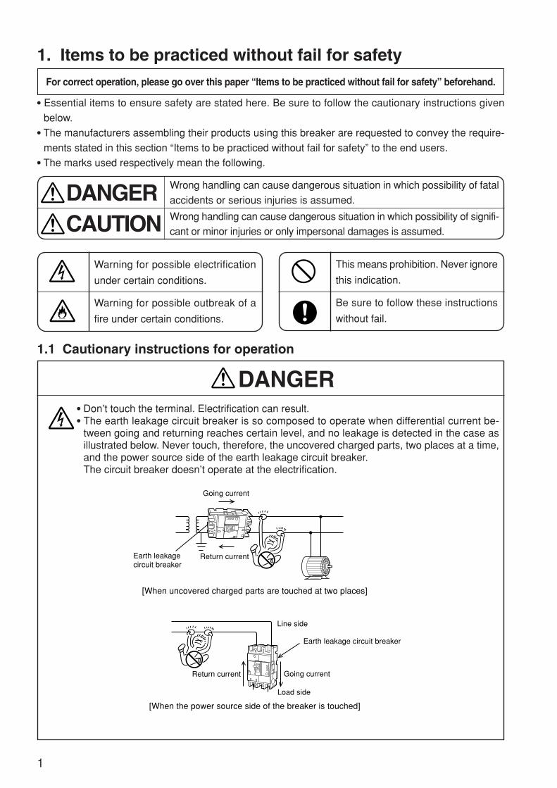
Don’t touch the terminal. Electrification can result. The earth leakage circuit breaker is so composed to operate when differential current be-
tween going and returning reaches certain level, and no leakage is detected in the case asillustrated below. Never touch, therefore, the uncovered charged parts, two places at a time,and the power source side of the earth leakage circuit breaker.The circuit breaker doesn’t operate at the electrification.
1
DANGER
Line side
Load side
Earth leakage circuit breaker
Earth leakage circuit breaker
Going current
Going current
Return current
Return current
[When uncovered charged parts are touched at two places]
[When the power source side of the breaker is touched]
ON
ON

Layman’s work is dangerous. Any electric work must be carried out by a qualified person(electrician).
When the breaker cuts off automatically, turn it on after eliminating the cause. Otherwise,electrification and fire can result.If the cause is unknown, please contact us at our service station, branch offices, local offices,or ask an electrician in your country.
Be sure to earth all the electrical devices of the circuits in which the earth leakage circuitbreaker is used.
Check operation of the earth leakage circuit breaker once a monthor so by pressing the test button.The breaker is out of order if it isn’t turned to “OFF” or “TRIP.”Please get in touch with us at our service stations, branch offices,local offices, or ask an electrician in your country.
Maintenance and inspection must be practiced by a specialist having electrical knowledge. Before maintenance & inspection, turn off the upper circuit breaker and make sure of no
current conducting to avoid possible electrification.
Retighten the terminals regularly according to theinspection manual. Otherwise, fire can take place.
1.2 Cautionary instructions for maintenance & inspection
2
CAUTION
CAUTION
5.2 Periodical inspectionAs for fastening torque, refer toAppendix 2.
( )
ON
Earth leakage circuit breaker Electric device (including household electric appliance)
Grounding work
ON
Procedure 1: Upper circuit breaker (Turn OFF)
Objective circuit breaker for maintenance & inspection
Procedure 2: With a detector, make sure of no current conducting.
OFF
OFF
3
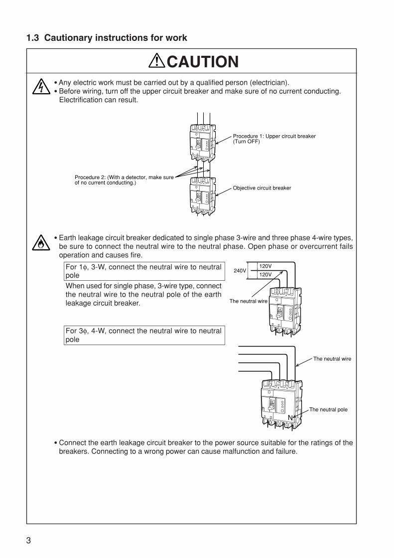
Any electric work must be carried out by a qualified person (electrician). Before wiring, turn off the upper circuit breaker and make sure of no current conducting.
Electrification can result.
Earth leakage circuit breaker dedicated to single phase 3-wire and three phase 4-wire types,be sure to connect the neutral wire to the neutral phase. Open phase or overcurrent failsoperation and causes fire.
For 1φ, 3-W, connect the neutral wire to neutralpoleWhen used for single phase, 3-wire type, connectthe neutral wire to the neutral pole of the earthleakage circuit breaker.
For 3φ, 4-W, connect the neutral wire to neutralpole
Connect the earth leakage circuit breaker to the power source suitable for the ratings of thebreakers. Connecting to a wrong power can cause malfunction and failure.
1.3 Cautionary instructions for work
CAUTION
Procedure 1: Upper circuit breaker (Turn OFF)
Objective circuit breaker
Procedure 2: (With a detector, make sure of no current conducting.)
OFF
OFF
OFF
240V120V
120V
The neutral wire
The neutral wire
The neutral poleOFF

At wire connection, fasten the terminal screws with the torque stated in the instruction manual.Fastening with incorrect torque can cause fire.
4
CAUTION
Terminalscrew
Screwdiameter
M5
Shape
M8 M12M6
FasteningtorqueN·m
2~3 2.5~4.0 5.0~7.0 8.0~13.0 8.0~13.0 40.0~50.0
30.0~40.0
Solderlessterminalscrew
Screwdiameter
M6
Shape
M10
FasteningtorqueN·m
4.0~6.0 3.5~4.5 20.0~30.0 30.0~40.0 50.0~60.0
M16 M18 M20 M24
Refrain from installing in abnormal environment such as high temperature, high humidity,high dust content, corrosive gas ambient, or of excessive vibration or impact. Electrification,fire, or operation failure can result.
Carry out the work avoiding foreign matters such as dust, concrete powder, steel chips, andrain water to enter into the equipment. Otherwise, operation failure can result.
Example of front connection type fastening torque (Others are in Appendix 2.)
Size of conductor,AWG or kcmll(mm2)
Tightening torque[N·m]
14(2.1)
12(3.3)
10(5.3)
8(8.4)
6(13.3)
4(21.2)
3(26.7)
2(33.6)
1(42.4)
1/0(53.5)
2/0(67.4)
3/0(85.0)
4/0(107)
250(127)
300(152)
350(177)
Size of conductor,IEC(mm2)
2.5
4.0
6.0
10
16
25
35
–
50
–
70
95
–
120
150
185
4
4
4
4.5
5.1
5.1
6.5
6.5
6.5
6.5
6.5
ー
ー
ー
ー
ー
5
5
5
13
13
13
13
13
13
13
13
25.5
25.5
25.5
25.5
25.5
NF125-CWNF125-SWNF125-HW
NV125-CWNV125-SWNV125-HWNV125-RW
NF125-SGWNF125-HGWNF125-RGWNF125-UGW
NF160-SGWNF160-HGWNF250-SGWNF250-HGWNF250-RGWNF250-UGW
Tightening torque for Solderless terminal

2. Before usingBesides operation, the items in this section are also applicable to work, maintenance and inspection.
2.1 Cautionary instructions in general
5
(1) Refrain from touching the terminal unit as electrification can result.Note: Besides the terminal of the circuit breaker, the terminal unit includes the wires, busbars, ring-type terminals, and other wiring materials.
(1) Layman’s work is dangerous. Any electrical work must be carried out by a qualified person(electrician).
(2) Be sure to earth all the electrical devices of the circuits in which the earth leakage circuitbreaker is used.
(3) Check operation of the earth leakage circuit breaker oncea month or so by pressing the test button.The breaker is out of order if it isn’t turned “OFF” or “TRIP”.Please contact us at our service stations, branch offices,local offices, or ask an electrician in your country.
CAUTION
DANGER
ON
Earth leakage circuit breaker Electrical equipment (including household appliances)
Grounding work
ON
6
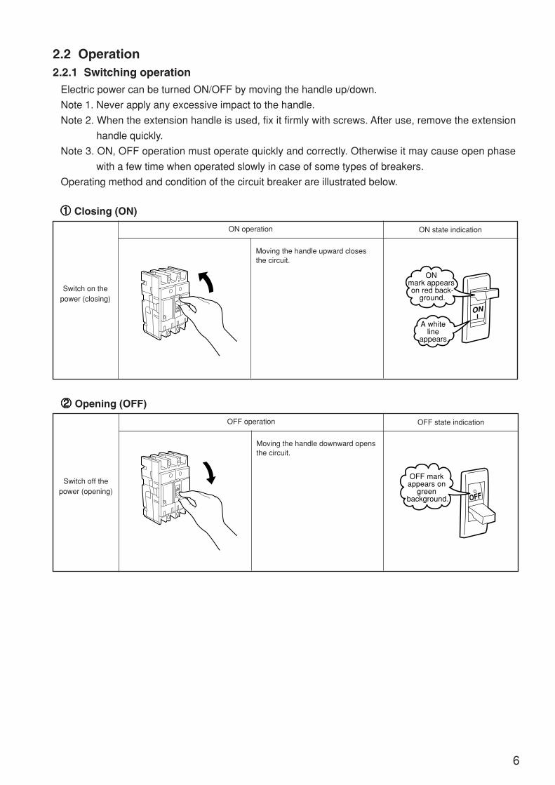
2.2 Operation2.2.1 Switching operation
Electric power can be turned ON/OFF by moving the handle up/down.
Note 1. Never apply any excessive impact to the handle.
Note 2. When the extension handle is used, fix it firmly with screws. After use, remove the extension
handle quickly.
Note 3. ON, OFF operation must operate quickly and correctly. Otherwise it may cause open phase
with a few time when operated slowly in case of some types of breakers.
Operating method and condition of the circuit breaker are illustrated below.
11111 Closing (ON)
Switch on thepower (closing)
ON operation ON state indication
Moving the handle upward closesthe circuit.
22222 Opening (OFF)
Switch off thepower (opening)
OFF operation OFF state indication
Moving the handle downward opensthe circuit.
ON ON
A white line
appears.
ON mark appears on red back-
ground.
OFF
OFF
OFF mark appears on
green background.
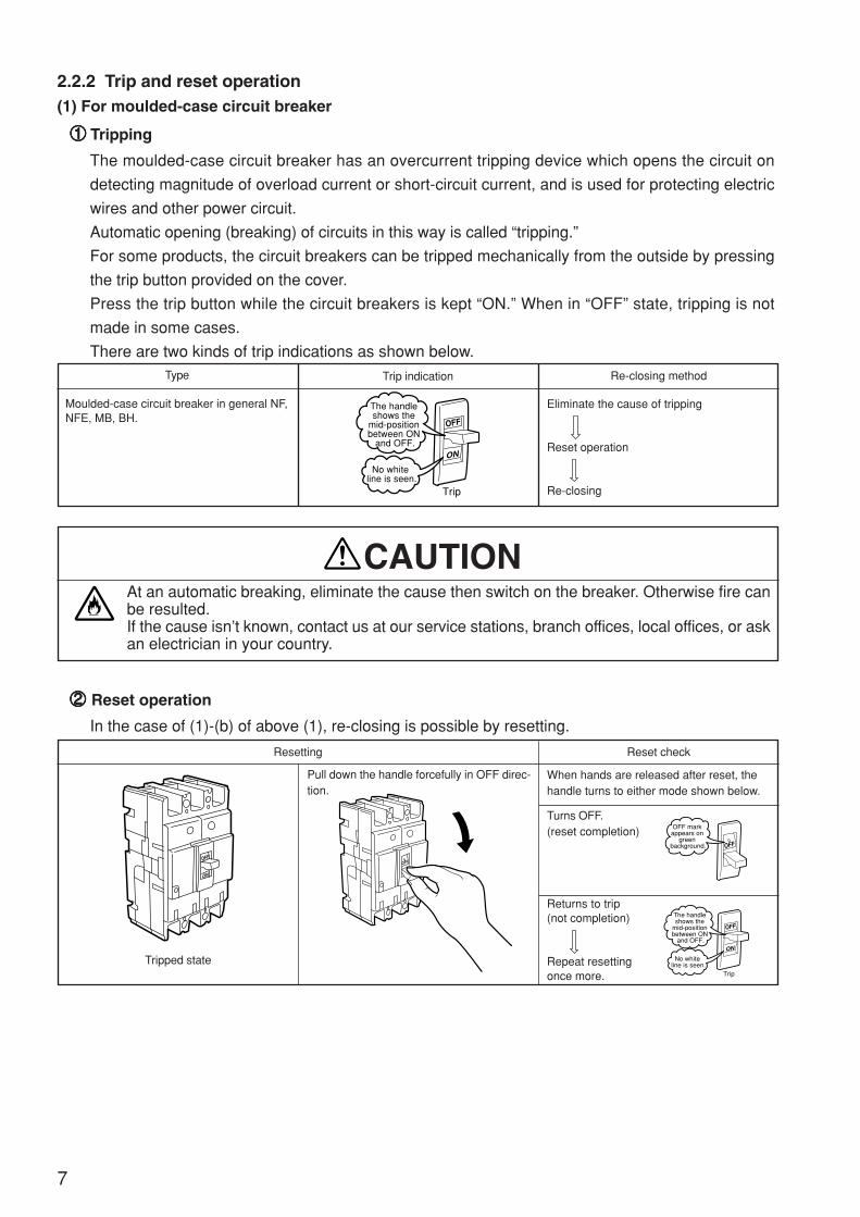
2.2.2 Trip and reset operation(1) For moulded-case circuit breaker
11111 Tripping
The moulded-case circuit breaker has an overcurrent tripping device which opens the circuit on
detecting magnitude of overload current or short-circuit current, and is used for protecting electric
wires and other power circuit.
Automatic opening (breaking) of circuits in this way is called “tripping.”
For some products, the circuit breakers can be tripped mechanically from the outside by pressing
the trip button provided on the cover.
Press the trip button while the circuit breakers is kept “ON.” When in “OFF” state, tripping is not
made in some cases.
There are two kinds of trip indications as shown below.Type Trip indication Re-closing method
Moulded-case circuit breaker in general NF,NFE, MB, BH.
Eliminate the cause of tripping
Reset operation
Re-closing
At an automatic breaking, eliminate the cause then switch on the breaker. Otherwise fire canbe resulted.If the cause isn’t known, contact us at our service stations, branch offices, local offices, or askan electrician in your country.
22222 Reset operation
In the case of (1)-(b) of above (1), re-closing is possible by resetting.
Resetting Reset check
When hands are released after reset, thehandle turns to either mode shown below.
Turns OFF.(reset completion)
Returns to trip(not completion)
Repeat resettingonce more.
Pull down the handle forcefully in OFF direc-tion.
Tripped state
7
CAUTION
OFF
ON
Trip
The handle shows the
mid-position between ON
and OFF.
No white line is seen.
OFF
ON
OFF
OFF
OFF mark appears on
green background.
OFF
ON
Trip
The handle shows the
mid-position between ON
and OFF.
No white line is seen.

Automatically reset when the handle is turnedto ON position.
NV30-CS·50-CSA
NV63-CW~600-CWNV32-SW~1200-SB
Type Leakage indicator reset
(2) For earth leakage circuit breaker
11111 Trip
Tripping of earth leakage circuit breaker includes two kinds; leak trip in which magnitude of leakage
is detected for automatic tripping (open circuit), and overcurrent trip in which magnitude of overload
current or short-circuit current is detected for automatic tripping.
For distinction of two kinds of tripping, the leak indication button comes out at leak trip only. The
indication button also comes out when the leak test button is pushed for checking leak current
operation.
Type Handle indicationLeakage indication button
Overcurrent trip or tripping bytrip button
Leakage trip; tripping byleakage test button
NV, MN
When the breaker cuts off automatically, turn ON the handle after eliminating the cause.Otherwise, electrification and fire can take place.If the cause isn’t known, contact us at our service stations, branch offices, local offices, or askan electrician in your country.
22222 Reset operation
When the leakage indication button comes out, remove the cause of failure, reset in the following
procedure, then close the circuit again.
Handle reset
Push down forcefully thehandle in OFF direction.
Automatically reest when the handle is reset.
Reset the handle.
8
CAUTION
OFF
ON
Trip
The handleindicates
middle position of ON and
OFF.
No white line is seen.
OFF
ON
Not come-out
Leakage indicationbutton (white)
Come-out
Leakage indicationbutton (white)
OFF
ON
OFF

Push in the reset button by a finger.
9
(3) For earth leakage relay
11111 Operation
When leakage is detected by the earth leakage relay, contact point output is given, the leakage
indicator button comes out, or the leakage indication lamp glows.
22222 Reset operation
When the leakage indication button comes out or the leakage indication lamp glows, removethe cause then reset before starting operation again. Otherwise, electrification can result.If the cause isn’t known, contact us at our service stations, branch offices, local offices, or askan electrician in your country.
(4) Circuit protector
11111 Trip
The handle turns off at tripping.
Note: Where an alarm switch is attached, the handle stops between ON and OFF positions.
22222 Reset
Eliminate the cause of tripping, then close. (Resetting isn’t necessary as the circuit protector is
reset automatically.)
Note: When an alarm switch is attached, move the handle to OFF side once, then to ON side for
reclosing. (The alarm switch of CP30-BA is reset at ON operation.)
Type
NV-ZSA, NV-ZLA
NV- ZU, NV-ZBA
NV-ZHA
Handle reset
—
—
Leakage indicator resetPush to the projected reset button for leakage indicator.Pushing the reset button turns off the leak indicationlamp and resets. Turning off the control power also re-sets automatically.
CAUTION
10
2.3 How to set current rating, trip characteristic, sensitive current and oper-
ating time2.3.1 Cautionary instructions for setting
Let a person having technical knowledge of electricity set the breaker. Before setting, turn off the upper circuit breaker, or turn off the circuit breaker to be set or trip
the breaker, then make sure of no current conducting.Otherwise, electrification can result.
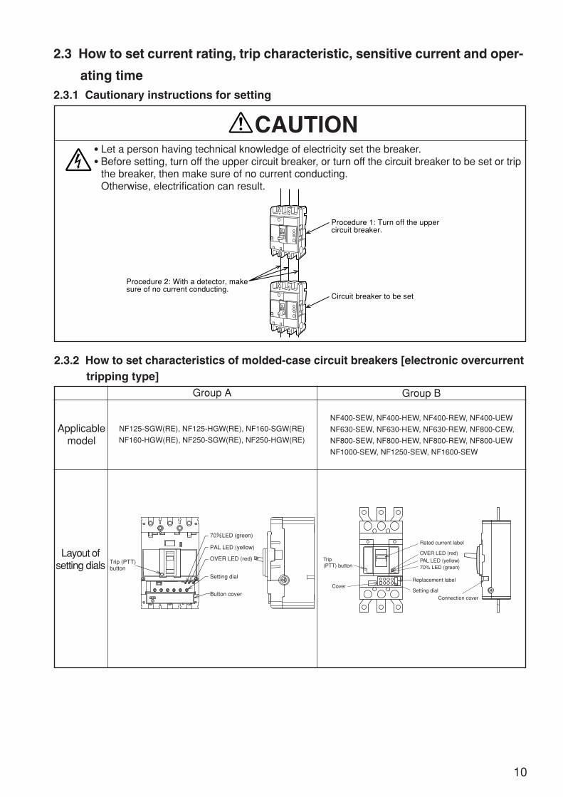
2.3.2 How to set characteristics of molded-case circuit breakers [electronic overcurrenttripping type]
Applicablemodel
Layout ofsetting dials
Group A Group B
NF125-SGW(RE), NF125-HGW(RE), NF160-SGW(RE)
NF160-HGW(RE), NF250-SGW(RE), NF250-HGW(RE)
NF400-SEW, NF400-HEW, NF400-REW, NF400-UEW
NF630-SEW, NF630-HEW, NF630-REW, NF800-CEW,
NF800-SEW, NF800-HEW, NF800-REW, NF800-UEW
NF1000-SEW, NF1250-SEW, NF1600-SEW
CAUTION
Procedure 1: Turn off the upper circuit breaker.
Circuit breaker to be set
Procedure 2: With a detector, makesure of no current conducting.
OFF
OFF
Connection cover
Trip(PTT) button 70% LED (green)
PAL LED (yellow)
OVER LED (red)
Setting dial
Replacement label
Rated current label
Cover
Setting dial
OVER LED (red)
70%LED (green)
PAL LED (yellow)
Button cover
Trip (PTT)button
SEALED
SEALED
SEALED
SEALED
11
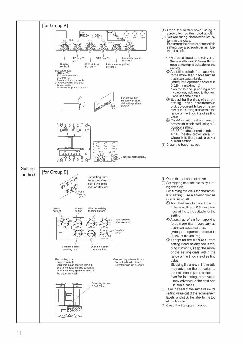
(1) Open the button cover using ascrewdriver as illustrated at left.
(2) Set operating characteristics byturning the dials.For turning the dials for chracteristicsetting,use a screwdriver as illus-trated at left.a
1 A slotted head screwdriver of3mm width and 0.5mm thick-ness at the top is suitable for thesetting.
2 At setting,refrain from applyingforce more than necessary assuch can cause broken.(Adequate operation torque is0.02N·m maximum.)* As for Is and Ip setting,a set
value may advance to the nextone in some cases
3 Except for the dials of currentsetting Ir and instantaneouspick up current Ir keep the ar-row of the setting dials within therange of the thick line of settingvalue.
4 On 4P circuit breakers, neutralprotection is selected using a 2-position setting:4P 3E (neutral unprotected),4P 4E (neutral protection at Ir),where Ir is the circuit breakercurrent setting.
(3) Close the button cover.
Settingmethod
[for Group B]
[for Group A]
Fastening torque0.3~0.6N·m
For setting, turn the arrow of each dial to the position desired
Step setting type: LTD time TL, STD pick up current IS, STD time TS, Pre-alarm pick up current IP Continuously adjustable type: Current setting Ir Instantaneous pick up current Ii
LTD time TL Note 1)
Pre-alarm pick up current IP
STD time TS
Instantaneous pick up current Ii
Current setting Ir
STD pick up current IS
Neutral protection INp
Ii(×250A)Is(×Ir) Ts(s) Ip(×Ir)TL(s)Ir(A)
Ip(×Ir)
.95
.9.85.8
1.0.7
4P3E 4P4E
INp
70% PAL OVER
IT
.75
50/60Hz(AC only)
.06
.1.2
.312
60 80
100
TEST
MODEL
150
125
175 200
225
250
6
4
8
12
10
142.52
54
33.5
76
8
10
.95.9.85
.75
.8
1.0.7
A250RE250 In70% PAL OVER
Ts
Is
Ii
T
I
TL
IrIp
(1) Open the transparent cover.(2) Set tripping characteristics by turn-
ing the dials.For turning the dials for character-istic setting, use a screwdriver asillustrated at left.1 A slotted head screwdriver of
4.5mm width and 0.6 mm thick-ness at the top is suitable for thesetting.
2 At setting, refrain from applyingforce more than necessary assuch can cause failures.(Adequate operation torque is0.05N·m maximum.)
3 Except for the dials of currentsetting lr and instantaneous trip-ping current ll, keep the arrowof the setting dials within therange of the thick line of settingvalue.Stopping the arrow in the middlemay advance the set value tothe next one in some cases.* As for Is setting, a set value
may advance to the next onein some cases.
(3) Take the seal of the same value forsetting value out of the replacementlabels, and stick the label to the topof the handle.
(4) Close the transparent cover.
For setting, turnthe arrow of eachdial to the scaleposition desired
Step setting type: Rated current In Long time-delay operating time TL
Short time-delay tripping current IS Short time-delay operating time TS
Pre-alarm current IP
Continuously adjustable type: Current setting Ir (Note 1) Instantaneous trip current II
Rated current
Currentsetting
Long time-delayoperating time
Short time-delaytripping current
Instantaneoustripping current
Pre-alarmcurrent
Short time-delayoperating time
4 5 67810 4
6
8 10121416
3
2
100
.06 .3
.1 .2
.7
.8 .9
1.0
60
12150
300350
250225
200In(A)
TEST
TL(s) TS(s) IP(×In, Ir)
IS(×In, Ir) II(×400A)
.5
.7 .8
1
Ir(×400A)

12
2.3.3 How to set characteristics of molded-case circuit breakers [electronic overcurrenttripping type]
Applicable model
Item
Layout ofsetting
terminals
Setting method
ETR (Electronic trip relay) mounting circuit breaker(NF1250-UR)
Rated current Short time-delay tripping characteristic
(1) Take off the seal, loosen the cover set screw andtake off the cover.
(2) Loosen the rated current switching screw, move itto the position desired for setting by fingers, andtighten it with 0.3 to 0.45 N·m torque.A slotted head screwdriver of 4.5mm width and0.6mm thickness at the top is suitable for the set-ting.
(3) Take the label and the seal of the same value forsetting value out of the replacement labels.
(4) Change the rated current label at the top end ofthe handle.
(5) Attach the cover, and stick the seal.
(1) Remove the seal, loosen the cover set screw, andtake off the cover.
(2) Loosen the short limit pickup current switchingscrew, move it to the desired setting positon byfingers, and tighten it with 0.3 to 0.45 N·m torque.A slotted head screwdriver of 4.5mm width and0.6mm thickness at the top is suitable for the set-ting.
(3) Take the seal out of the replacement labels.(4) Attach the cover and stick the seal.
2.3.4 How to set characteristics of molded-case circuit breakers [Applicable models:NFE2000-S, NFE3000-S, NFE4000-S]
Remarks: For the electronic circuits of circuit breaker, control power is supplied from the built-in current transformer.Accordingly, the breakers can be used with no regard to circuit voltage.
Rated current label
Rated current switching screwSeal
Cover
Electronic typetrip relay unit(with cover)
Cover set screw(Lower side of seal)
Replacement labels(Rated current, seal)
Short time-delay pickup currentswitching screw
Scale setting method
PUSH TO TRIP(Trip button)The button is formechanically tripping.Use the trip button forsequence check onlyand refrain from usingit for ordinary opencircuit operation.
Ampere rating(Rated current adjustable dial)Set at any rated current desired
SHORT-DERAY PICK UP(Short time-delay tripping adjustable dial)Set at a desired short limit trip characteristic.
TEST TERMINALRefrain from using thisterminal normally as it isfor checking trippingcharacteristic using thetester offered separately.
PUSH TO TRIP
INSTANTANEOUS PICK UPCURRENT 30000A (FIXED)
TEST TERMINAL
1600
20001200
MED
MIN. MAX.
AMPERERATING
SHORT-DELAYPICK UP
13
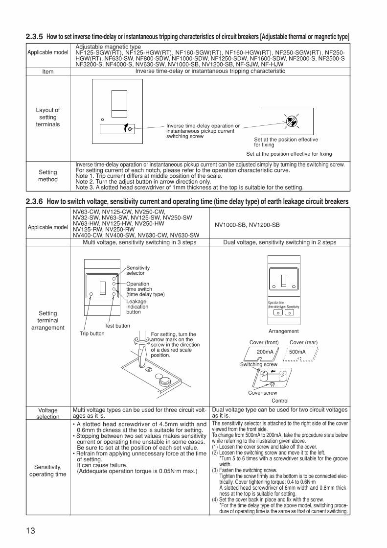
2.3.5 How to set inverse time-delay or instantaneous tripping characteristics of circuit breakers [Adjustable thermal or magnetic type]
Applicable model
Item
Layout ofsetting
terminals
Settingmethod
Adjustable magnetic typeNF125-SGW(RT), NF125-HGW(RT), NF160-SGW(RT), NF160-HGW(RT), NF250-SGW(RT), NF250-HGW(RT), NF630-SW, NF800-SDW, NF1000-SDW, NF1250-SDW, NF1600-SDW, NF2000-S, NF2500-SNF3200-S, NF4000-S, NV630-SW, NV1000-SB, NV1200-SB, NF-SJW, NF-HJW
Inverse time-delay or instantaneous tripping characteristic
Inverse time-delay oparation or instantaneous pickup current can be adjusted simply by turning the switching screw.For setting current of each notch, please refer to the operation characteristic curve.Note 1. Trip current differs at middle position of the scale.Note 2. Turn the adjust button in arrow direction only.Note 3. A slotted head screwdriver of 1mm thickness at the top is suitable for the setting.
2.3.6 How to switch voltage, sensitivity current and operating time (time delay type) of earth leakage circuit breakers
Applicable model
Settingterminal
arrangement
Voltageselection
Sensitivity,operating time
NV63-CW, NV125-CW, NV250-CW,NV32-SW, NV63-SW, NV125-SW, NV250-SWNV63-HW, NV125-HW, NV250-HWNV125-RW, NV250-RWNV400-CW, NV400-SW, NV630-CW, NV630-SW
Multi voltage, sensitivity switching in 3 steps Dual voltage, sensitivity switching in 2 steps
NV1000-SB, NV1200-SB
Multi voltage types can be used for three circuit volt-ages as it is.
Dual voltage type can be used for two circuit voltagesas it is.
• A slotted head screwdriver of 4.5mm width and0.6mm thickness at the top is suitable for setting.
• Stopping between two set values makes sensitivitycurrent or operating time unstable in some cases.Be sure to set at the position of each set value.
• Refrain from applying unnecessary force at the timeof setting.It can cause failure.(Addequate operation torque is 0.05N·m max.)
The sensitivity selector is attached to the right side of the coverviewed from the front side.To change from 500mA to 200mA, take the procedure state belowwhile referring to the illustration given above.(1) Loosen the cover screw and take off the cover.(2) Loosen the switching screw and move it to the left.
*Turn 5 to 6 times with a screwdriver suitable for the groovewidth.
(3) Fasten the switching screw.Tighten the screw firmly as the bottom is to be connected elec-trically. Cover tightening torque: 0.4 to 0.6N·mA slotted head screwdriver of 6mm width and 0.8mm thick-ness at the top is suitable for setting.
(4) Set the cover back in place and fix with the screw.*For the time delay type of the above model, switching proce-dure of operating time is the same as that of current switching.
Inverse time-delay oparation orinstantaneous pickup currentswitching screw
Set at the position effectivefor fixing
Set at the position effective for fixing
Sensitivityselector
Operationtime switch(time delay type)Leakageindicationbutton
Trip button
Test button
For setting, turn thearrow mark on thescrew in the directionof a desired scaleposition.
Operation time(time delay type) Sensitivity
Arrangement
Cover (front)
200mA
Cover (rear)
500mA
Switching screw
Cover screw
Control
14
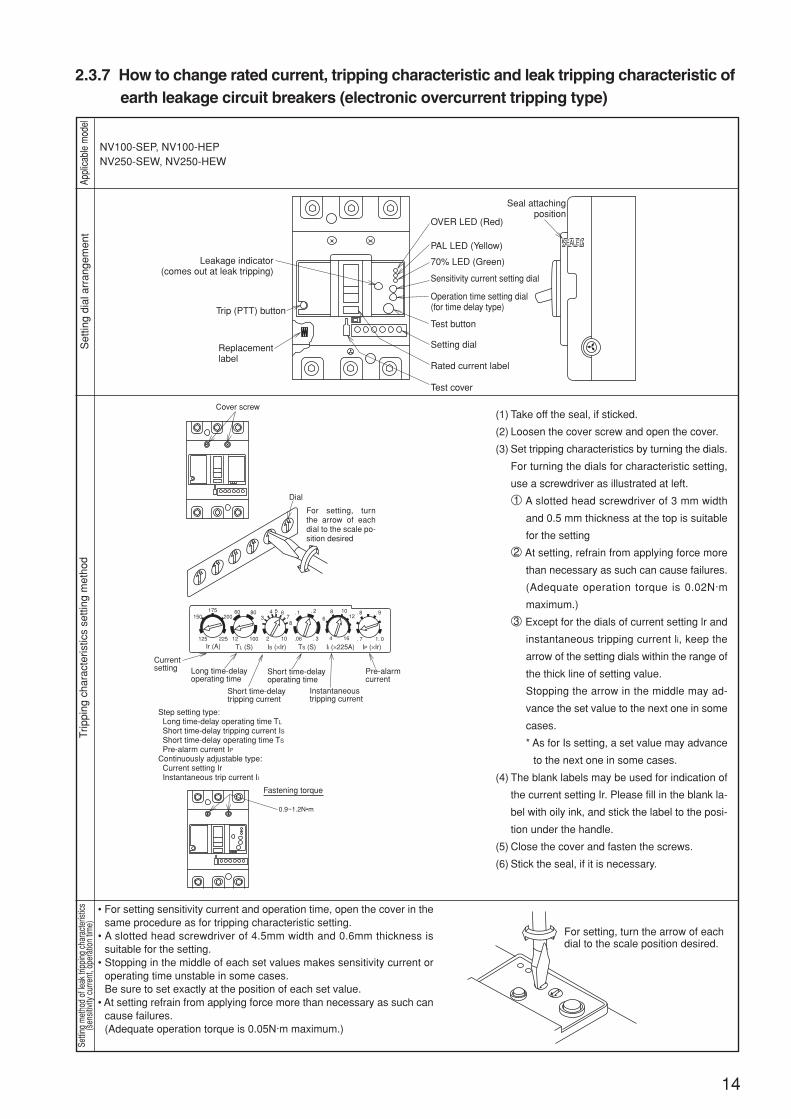
2.3.7 How to change rated current, tripping characteristic and leak tripping characteristic ofearth leakage circuit breakers (electronic overcurrent tripping type)
Appl
icabl
e m
odel
Set
ting
dial
arr
ange
men
tTr
ippi
ng c
hara
cter
istic
s se
tting
met
hod
Setti
ng m
etho
d of
leak
trip
ping
cha
ract
erist
ics(s
ensit
ivity
cur
rent
, ope
ratio
n tim
e)
NV100-SEP, NV100-HEPNV250-SEW, NV250-HEW
(1) Take off the seal, if sticked.
(2) Loosen the cover screw and open the cover.
(3) Set tripping characteristics by turning the dials.
For turning the dials for characteristic setting,
use a screwdriver as illustrated at left.
1 A slotted head screwdriver of 3 mm width
and 0.5 mm thickness at the top is suitable
for the setting
2 At setting, refrain from applying force more
than necessary as such can cause failures.
(Adequate operation torque is 0.02N·m
maximum.)
3 Except for the dials of current setting lr and
instantaneous tripping current li, keep the
arrow of the setting dials within the range of
the thick line of setting value.
Stopping the arrow in the middle may ad-
vance the set value to the next one in some
cases.
* As for Is setting, a set value may advance
to the next one in some cases.
(4) The blank labels may be used for indication of
the current setting Ir. Please fill in the blank la-
bel with oily ink, and stick the label to the posi-
tion under the handle.
(5) Close the cover and fasten the screws.
(6) Stick the seal, if it is necessary.
• For setting sensitivity current and operation time, open the cover in thesame procedure as for tripping characteristic setting.
• A slotted head screwdriver of 4.5mm width and 0.6mm thickness issuitable for the setting.
• Stopping in the middle of each set values makes sensitivity current oroperating time unstable in some cases.Be sure to set exactly at the position of each set value.
• At setting refrain from applying force more than necessary as such cancause failures.(Adequate operation torque is 0.05N·m maximum.)
Seal attachingposition
OVER LED (Red)
PAL LED (Yellow)
70% LED (Green)
Sensitivity current setting dial
Rated current label
Test cover
Operation time setting dial(for time delay type)
Leakage indicator(comes out at leak tripping)
Trip (PTT) button
Replacementlabel
Test button
Setting dial
SEALED
200175
150
125 225
80
2 10 .06 . 3
. 1 . 2
. 7
. 8 . 9
1. 0
34 5 6
78
60
12 100
Ir (A) TL (S) TS (S)IS (×Ir) Ii (×225A) IP (×Ir)
Cover screw
Dial
Currentsetting
Step setting type: Long time-delay operating time TL
Short time-delay tripping current IS Short time-delay operating time TS
Pre-alarm current IPContinuously adjustable type: Current setting Ir Instantaneous trip current Ii
Long time-delayoperating time
Short time-delayoperating time
Short time-delaytripping current
Instantaneoustripping current
Fastening torque
0.9~1.2N•m
Pre-alarmcurrent
For setting, turnthe arrow of eachdial to the scale po-sition desired
610812
164
For setting, turn the arrow of eachdial to the scale position desired.
For setting, turn the arrowof each dial to the scaleposition desired.
15
Appl
icabl
e m
odel
Set
ting
dial
arr
ange
men
tTr
ippi
ng c
hara
cter
istic
s se
tting
met
hod
Set
ting
met
hod
of le
ak tr
ippi
ng c
hara
cter
istic
s(s
ensi
tivity
cur
rent
, ope
ratio
n tim
e)
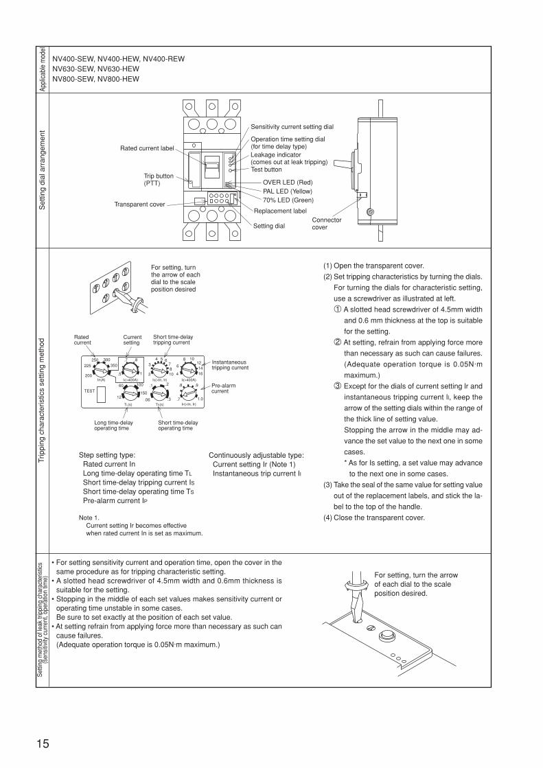
NV400-SEW, NV400-HEW, NV400-REWNV630-SEW, NV630-HEWNV800-SEW, NV800-HEW
(1) Open the transparent cover.
(2) Set tripping characteristics by turning the dials.
For turning the dials for characteristic setting,
use a screwdriver as illustrated at left.
1 A slotted head screwdriver of 4.5mm width
and 0.6 mm thickness at the top is suitable
for the setting.
2 At setting, refrain from applying force more
than necessary as such can cause failures.
(Adequate operation torque is 0.05N·m
maximum.)
3 Except for the dials of current setting lr and
instantaneous tripping current ll, keep the
arrow of the setting dials within the range of
the thick line of setting value.
Stopping the arrow in the middle may ad-
vance the set value to the next one in some
cases.
* As for Is setting, a set value may advance
to the next one in some cases.
(3) Take the seal of the same value for setting value
out of the replacement labels, and stick the la-
bel to the top of the handle.
(4) Close the transparent cover.
• For setting sensitivity current and operation time, open the cover in thesame procedure as for tripping characteristic setting.
• A slotted head screwdriver of 4.5mm width and 0.6mm thickness issuitable for the setting.
• Stopping in the middle of each set values makes sensitivity current oroperating time unstable in some cases.Be sure to set exactly at the position of each set value.
• At setting refrain from applying force more than necessary as such cancause failures.(Adequate operation torque is 0.05N·m maximum.)
OVER LED (Red)PAL LED (Yellow)70% LED (Green)
Sensitivity current setting dial
Rated current label
Connectorcover
Operation time setting dial(for time delay type)Leakage indicator(comes out at leak tripping)
Trip button(PTT)
Transparent coverReplacement label
Test button
Setting dial
For setting, turnthe arrow of eachdial to the scaleposition desired
Step setting type: Rated current In Long time-delay operating time TL
Short time-delay tripping current IS Short time-delay operating time TS
Pre-alarm current IP
Continuously adjustable type: Current setting Ir (Note 1) Instantaneous trip current II
Note 1.Current setting Ir becomes effective when rated current In is set as maximum.
Rated current
Currentsetting
Long time-delayoperating time
Short time-delaytripping current
Instantaneoustripping current
Pre-alarmcurrent
Short time-delayoperating time
4 5 67810 4
6
8 10121416
3
2
100
.06 .3
.1 .2
.7
.8 .9
1.0
60
12150
300350
250225
200In(A)
TEST
TL(s) TS(s) IP(×In, Ir)
IS(×In, Ir) II(×400A)
.5
.7 .8
1
Ir(×400A)
16
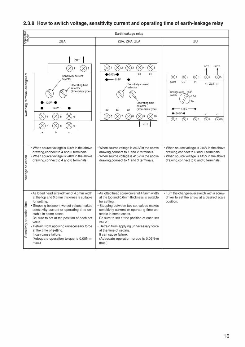
2.3.8 How to switch voltage, sensitivity current and operating time of earth-leakage relayA
pplic
able
mod
elS
witc
hing
term
inal
arr
angm
ent
Vol
tage
sel
ectio
n
ZBA
• When source voltage is 120V in the abovedrawing,connect to 4 and 5 terminals.
• When source voltage is 240V in the abovedrawing,connect to 4 and 6 terminals.
Earth leakage relay
Sen
sitiv
ity,o
pera
tion
time
• As lotted head screwdriver of 4.5mm widthat the top and 0.6mm thickness is suitablefor setting.
• Stopping between two set values makessensitivity current or operating time un-stable in some cases.Be sure to set at the position of each setvalue.
• Refrain from applying unnecessary forceat the time of setting.It can cause failure.(Adequate operation torque is 0.05N·mmax.)
ZCT ZCT
3 421
415V
240V
ZCT
5
876 9 10
COM OUT IN
a1 c1
Change-overswitch
0.2A
0.5A
1A
ZSA, ZHA, ZLA ZU
• When source voltage is 240V in the abovedrawing,connect to 1 and 2 terminals.
• When source voltage is 415V in the abovedrawing,connect to 1 and 3 terminals.
• As lotted head screwdriver of 4.5mm widthat the top and 0.6mm thickness is suitablefor setting.
• Stopping between two set values makessensitivity current or operating time un-stable in some cases.Be sure to set at the position of each setvalue.
• Refrain from applying unnecessary forceat the time of setting.It can cause failure.(Adequate operation torque is 0.05N·mmax.)
• When source voltage is 240V in the abovedrawing,connect to 6 and 7 terminals.
• When source voltage is 415V in the abovedrawing,connect to 6 and 8 terminals.
• Turn the change-over switch with a screw-driver to set the arrow at a desired scaleposition.
ZCT
1
Sensitivity currentselector
Operating timeselector(time-delay type)
3
4 5 6
240V
120V
7 8 9
a b c
ZCT
1 2 3 4 5
c1a1
c2b2a2
Sensitivity currentselector
Operating timeselector(time-delay type)
240V
415V
76 8 9 10
17
3. Installation3.1 Notice for selection
For selection, refer to the catalog, technical data, specifications and other technical materials.
For any question concerning the selection method, please enquire us.
We are not responsible for any failure and damage caused by wrong selection.
3.2 Normal service conditionsOur circuit breakers of the standard specifications are to be used in the following standard conditions.
• Operating ambient temperature: –10 to 40°C (Average temperature for 24 hours, however, shall
not be higher than 35°C.)
• Relative humidity: 85% max. with no dewing
• Altitude: 2,000 m maximum
• Ambient of no excessive water or oil vapour, smoke, dust, salt content, corrosive substance, vibra-
tion, and impact
Expected service life (MTTF) under the above conditions is 15 years.
• Lowering ratio of operational current in special ambient temperature over 40°C.
50°C………0.9 times
60°C………0.7 times
Expected service life (MTTF) will be reduced compare with normal service conditions.
Note. The environment shall be free from any dewing or freezing.
• Refrain from installing in any unusual environment of high temperature, high humidity, dust,corrosive gas, vibration and impact. Electrification, fire, and malfunction can result.
CAUTION

18
3.3 Non-standard conditionsWhen operated under different conditions from the normal service conditions, it is necessary to take
the following measures against the operating conditions.
Even with such measures taken, however, service life may become shorter in some cases.
Special environment Circuit breaker forspecial environment
SpecificationsApplicable model
MCCB ELCB
Lowtempera-
ture
Hightempera-ture, highhumidity
Corrosivegas, saltcontent
Dust,vapour
Freezing warehouse,low temperature room
Chemical plant
Chemical plant, Oilrefining plant
Cement plant, spinningmill, gravel pit
Enclosed circuitbreaker
Added corrosionresistive circuit
breaker
Circuit breaker forlow temperature
Circuit breaker formoisture-fungus
treatment
This breaker is so designed to enablepower supply, switching, and short cir-cuit breaking at -40°C. The operatingcharacteristics change at low tempera-ture as they are adjusted for the refer-ence ambient temperatur.(For storing, consider the use is pos-sible up to -50°C at the lowest.)
• Moisture-fungus treatment of the 1stkindIn addit ion to special surfacetreatment and special materials,corrosionproof treatment is applied.
• Moisture-fungus treatment of the 2ndkindSpecial surface treatment is appliedand special materials are used. In hu-mid environment, insulation strengthand other electrical performancestend to be lowered. The special sur-face treatment and the special ma-terials are used to avoid such dete-rioration.
• In the environment containing muchcorrosive gas (gas concentrationlevel up to the note *given below), itis advisable to use MCCB of addedcorrosion resistive specifications.F o r t h e b r e a k e r s o f a d d e dcorrosionproof type, corrosionproofplating is applied to the metal parts.
• Where concentration of corrosive gasexceeds the level stated below, it is nec-essary to use MCCB of added corro-sion resistive type being enclosed in awaterproof type enclosure or in any en-closure of protective structure.
* Concentration of corrosive gas al-lowed by the Safety and Health Stan-dard:(Ex.) H2S (10 ppm), HCI (5 ppm),
CI2 (1 ppm), SO2 (5 ppm),NH3 (25 ppm) - (Japan IndustrialHealth Association, since 1973)
Where concentration of corrosive gasis about 1/100 of the noted level andH2S (0.01 ppm), the standard MCCBcan be used.Expected service life (MTTF) will beless than 15 years.
Enclosed circuit breaker of dustproof (type I) or waterproof (type W) is advis-able for places where much dust or vapour is contained.For installing circuit breakers in explosionproof enclosure, use non-ammoniamould product.
• 1600 A frame ofS-ser ies andlower
• All models of C-series
• Moisture-fungustreatment of the1st kind (Note 2)Front connection,rear connection,and flush platetype of S-seriesand C-series of2000A frame andlower.
• Moisture-fungustreatment of the2nd kindAll models of S-and C- series
(Note 2)• Front connection,
rear connction,and flush platetype of series Sand C of 2000Aframe and smaller
(Note 2)
All models of S-and C- series
(Note 2)
All models of S-and C- series
All models of leak-age relay (Mois-ture-fungus treat-ment of the 2ndkind only)
–
Note 1. SHT and UVT of internal accessories are excluded.
2. Electronic types are excluded.

3.4 Inspection at arrival(1) Make sure that the packing case is free from any abnormality such as breaking and wetting.
(2) Referring to the name plate, make sure that the delivered breaker is in conformity with your order.
(3) Check for the parts contained in the same package.
1 Mounting screws
2 Terminal screws
3 Insulation barriers (The barrier is contained in the same package for some models, but not for other
models.)
4 Terminal covers (The cover is contained in the same package for some models, but not for others.)
Note: At unpacking, be careful so that the sealing pags may not be scattered around.
3.5 Conditions during transport and storage3.5.1 Transport
19
Packing and transportation shall becarried out with care
Don’t bring the breaker by holding theflash plate for carrying.
Don’t bring the breaker up withholding the wires for carrying.
Never drop the packing. Carrying in this manner is dangerousas the breaker may drop.
Holding on the attached lead wires of internalaccessories for carrying as unreasonable forceis applied to the attached wires.
Storage temperature Avoid humid air.Relative humidity: 85% max.
Avoid corrosive gas.
Average temperature for 24 hours,however, shall not be higher than 35°C.
• Don’t leave the breaker in a humidplace for a long time.
• Keep the breaker so as not be dewed.
Storage the breaker in the environmentof no corrosive gas.H2S 0.01 ppm max. SO2 0.05 ppm max.NH3 0.25 ppm max.
3.5.2 Storage
Place of low dust content Housed in a packing case for storage Avoid direct sunlight.
Avoid direct insolation during storage.
40°C
–20°C
Keep within this range. H2S
Ammonia

20
3.6 Installation and connection3.6.1 General
• Let a qualified person (electrician) carry out the electrical work.• Before wiring, turn the upper circuit breaker to OFF. Make sure that no power is supplied to
prevent that the electrification can occur.
CAUTION
Install the breaker in normal environment. In case of any unusual environments such as hightemperature, high humidity, dust, corrosive gas, vibration and impact, the fire, the malfunc-tion, and any operation failures can result.
CAUTION
3.6.2 Installation
Operating ambient temperature:–10°C to 40°C
Avoid humid air.Relative humidity 85% max.
Avoid corrosive gas. Avoid vibration and impact.
Average temperature for 24 hours,however, shall not be higher than35°C.
• Install the breakers in a place of low hu-midity
• Keep the breakers so as not be dewed.
Install the breakers in the environ-ment of no corrosive gas.H2S 0.01ppm max. SO2 0.05ppmmax. NH3 0.25ppm max.
CAUTIONUse care to avoid rain, drillchips and other chips.Malfunction and operation fail-ure can result.
Avoid direct exposure to rain, oil,dust and powder etc. Pay closeattention, in particular, to drillchips made from steel platesand other conductive wastes.
Cover the exhaust port with thesheet when under construction.
Malfunction and operation fail-ures can result.
Do not remove the compoundfilled in the threads at the rearsurface and the rear cover.
Be sure to use the breakers ina casing and never use thembeing exposed because arc isgenerated.
Don’t put dust and chipsinside through the ex-haust port.
Don’t disassemble! Use in a enclosure.
It is danger of poor electrifica-tion and abnormal temperaturerise.
Temperature rise can lead tomalfunction.
Install the breakers to the cor-rect position using the specifiedscrews (length and number ofpieces) or the specified fittings.
Breaking performance maypossibly be lowered.
Don’t block up the
exhaust port.Avoid direct sunlight. Use specified screws only.
Don’t put a flammable
parts near the breaker.
It is in danger of fire whenbreaking the circuit.
40°C
–10°C
Use within this range.
H2S
Ammonia
Screw
21
• At the time of wire connection, tighten the terminals screws with the tightening torque shownin Appendix 4.Otherwise, fire can result.
• Loose fastening leads to overheat and can cause malfunction.• Excessive fastening injures the screws and breaks the moulded case.• Use a screwdriver suitable for screw shape.
CAUTION
3.6.3 Connection
See to it so that rain water isn’tallowed to enter into the boardalong the wires, for example.
It is likely to make letters on theplate illegible or to lower insu-lation performance.
The name plate may come off.
Do not adhere gum tape
on the name plate.
Avoid strong electro
magnetic field.When a transceiver is used, keepit off at least 1 meter from installedplaces of the earth leakage circuitbreakers and circuit breakers withelectronic over-current release.
Prevent the ingress of
water into the enclosure.Never use thinner, detergent, and
other chemicals for cleaning.
Clean the breaker using aircleaner or by brushing.
Oil is prohibitiveto threads
Don't deform thestuds
Insulate the liveand exposed part
Use the terminal screwspacked together.
Use ring-type terminalsof suitable size.
Oiling lowers frictions lead-ing to loose screw. Overtightening causes breakageof the screw.
Fasten the conductors ofrear connection type with-out deforming the stud
When insulation distance isn't enough, or forthe live and exposed part of the terminal toprevent short-circuit or ground fault due tometal piece dropping, applying insulation bytaping, insulation tube, and insulation barrier.Of 400V and higher systems, in particular, un-covered conducting part is dangerous.Note. The model that a standard packs insu-
lation barrier together is to install insu-lation barrier.
Long terminal screw makesinsulation distance insuffi-cient, while short terminalscrew causes insufficienttightening force, whichleads to overheat.
Where a large number ofsolderless terminals areused for connection, con-nect them referring to Ap-pendix 4.
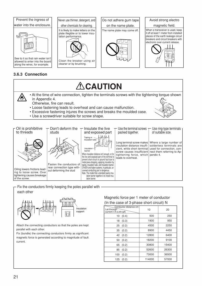
Fix the conductors firmly keeping the poles parallel witheach other
Attach the connecting conductors so that the poles are kept
parallel with each other.
Fix (bundle) the connecting conductors firmly as significant
magnetic force is generated according to magnitude of fault
current.
Magnetic force per 1 meter of conductor(In the case of 3-phase short circuit) N
Let-throughcurrent r.m.s.kA (pf)
Conductor distance cm
10 (0.4)
18 (0.3)
25 (0.2)
35 (0.2)
42 (0.2)
50 (0.2)
65 (0.2)
85 (0.2)
100 (0.2)
125 (0.2)
500
1900
4500
8900
12800
18200
30800
52600
73000
114000
10
250
950
2250
4450
6400
9100
15400
26300
36500
57000
ON
Taping or insulation tube
Insulation barrier
Insulationsupport
20
22
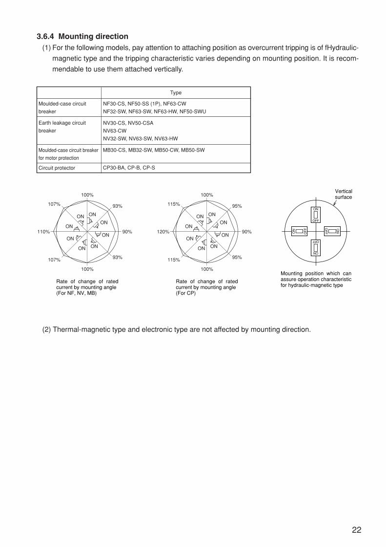
3.6.4 Mounting direction(1) For the following models, pay attention to attaching position as overcurrent tripping is of fHydraulic-
magnetic type and the tripping characteristic varies depending on mounting position. It is recom-
mendable to use them attached vertically.
Moulded-case circuit
breaker
Type
Moulded-case circuit breaker
for motor protection
Circuit protector
Earth leakage circuit
breaker
NF30-CS, NF50-SS (1P), NF63-CW
NF32-SW, NF63-SW, NF63-HW, NF50-SWU
NV30-CS, NV50-CSA
NV63-CW
NV32-SW, NV63-SW, NV63-HW
MB30-CS, MB32-SW, MB50-CW, MB50-SW
CP30-BA, CP-B, CP-S
(2) Thermal-magnetic type and electronic type are not affected by mounting direction.
110%
107%
100%
100%
107% 93%
93%
90%
ON
ON
ON
ONON
ON
ON
ON
Rate of change of rated current by mounting angle(For NF, NV, MB)
Vertical surface
ON
OFF
ON
OF
F
ON
OFF
ON
OF
F
Mounting position which can assure operation characteristic for hydraulic-magnetic type
120%
115%
100%
100%
115% 95%
95%
90%
ON
ON
ON
ONON
ON
ON
ON
Rate of change of rated current by mounting angle(For CP)

23
3.6.5 Distances between circuit breaker and earthed metal partsWhen short circuit current is cut off, ionized gas goes out of the exhaust port at the power source sideof the circuit breaker. At the power source side of the circuit breaker, provide the insulation distanceshown in the table so that the outgoing gas may not be bothered. Short circuit and ground fault canalso be resulted by dropped metal pieces, abnormal surge voltage generated in the lines, or by dust,iron chip, and salt content. Insulate uncovered conductors at the power source side of the circuitbreaker exactly using insulation barriers, insulation tubes, and tapes.
Note 1. The figures in parentheses in the table are the dimensions applied to AC 230 V andlower.
Note 2. Settle D2 dimension so that insulation distance (a according to each standard) canbe secured.
Note 3. When NVs at both sides are put in contact and 2500A or higher current flows throughNV at one side, the other NV may operate needless motion being affected by themagnetic field. In such a case, set D2 at 50mm or more.
Note 4. The terminal unit at the power side has no exhaust port and is so composed todischarge no arc requiring no insulation distance (space) to the power side. Whenan earth metal is put in contact with the terminal unit, however, uncovered part ofthe terminal or the wire must be insulated exactly using terminal covers, insulationbarriers, tubes, and tapes to secure insulation distance (space) to the earth metal(the distance specified in board specifications etc.).
Note 5. Where surface type uncovered bars are used for connection, insulate by taping tothe point where the bars overlap with the insulation barrier or to the root of thecircuit breaker.
Note 6. In case of over AC440V, the distance is 10mm.
708020020305050505050
NV30-CS, NV50-CSANV63-CWNV32-SW, NV63-SW, NV63-HWNV125-CWNV125-SWNV100-HEP, NV125-HWNV250-CWNV250-SW, NV250-SEWNF250-HW, NV250-HEW
—
NV400-CWNV400-SW, NV400-SEWNV400-HEW, REWNV630-CW, NV630-SW, NV630-SEWNV630-HEWNV800-SEWNV800-HEWNV1000-SB, NV1200-SB
——
NV125-RWNV250-RW
————
NV50-SWU (AC240V and less)—
NV100-SWU (AC240V and less)NV225-CWU (AC240V and less)
——
NF30-CS, MB30-CSNF32-SW, NF63-CW, MB30-SW, MB50-CWNF63-SW, NF63-HW, MB50-SWNF125-CWNF125-SW, MB100-SWNF125-HWNF250-CWNF160-SW, NF250-SW, MB225-SWNF160-HW, NF250-HWNF125-SGW, NF125-HGW, NF160-SGWNF160-HGW, NF250-SGW, NF250-HGWNF400-CWNF400-SW, NF400-SEWNF400-HEW, REWNF630-SW, NF630-SEW, NF630-CWNF630-HEW, REWNF800-SEW, NF800-CEWNF800-HEP, REPNF1000-SEW, NF1250-SEW, NF1250-SDW,NF1600-SEW, NF1600-SDW, NF2000-S,NF2500-S, NF3200-S, NF4000-SNF125-RGW, NF125-UGWNF250-RGW, NF250-UGW
——
NF400-UEWNF800-UEWNF1250-URBH, BH-P, BH-S, BH-PSNF50-SWU (AC240V and less)NF100-CWU (AC240V and less)NF100-SWU (AC480Y/277V and less)NF225-CWU (AC240V and less)NF-SFW, NF-SJW (AC600Y/480V and less)NF-HJW (AC600Y/480V and less)
Series Type name
Ceiling plate
A
Vertical spacing
B1, B2
Uncoveredmetal plate
Withoutterminal
cover
Withterminal
cover
Insu-latedplate,
coatedplate
With-out
termi-nal
cover
Withtermi-
nalcover
Horizontal spacing
C D1 D2
NFB NV
Type name
10510
50 (30)50 (10)
5040
70 (40)80
30
60702007020080200
100
10510
40 (30)30 (10)
40404060
30
60702007020080200
100
0(Note 4)
0(Note 4)
0(Note 4)
70802001010
50 (30)50 (10)
403030
708020010––––––
708020010101010403030
708020020305050505050
105
10101040404060
30
60702007020080200
100
20203050508050
70 (50)80
50
60702007020080200
100
202030505080505080
50
60702007020080200
100
202025252540505060
5
40701507015080150
100
5
(Note2)(Note3)U
BH
C·S·
MB
Larg
er th
an th
e di
men
sion
of e
xpos
ed c
ondu
ctin
g pa
rt (
Not
e 5)
May b
e put
in tig
ht co
ntact
(Note
2) (N
ote 3)
May
be
put i
n tig
ht c
onta
ct(N
ote
2) (
Not
e 3)
(Note 2)(Note 3)
May
be
put i
ntig
ht c
onta
ct(N
ote
2) (
Not
e 3)
Insulation distance mm (AC 440V and less)Distances are obtained tests defined in the IEC 60947-2 standard.
Ceiling plate
AB
1
(Direct connection of wire)
Ceiling plate
AB
1
(Connection with ring-type terminals)
Ceiling plate
AB
1
D1
D2
a
D2
(Bar connection)
Ceiling plate
A
C
B2
(Rear connection)
Note:Vertical distance differs by each type of the lower circuit breaker.A : Distance from circuit breaker to ceiling plateB1 : Distance from lower circuit breaker to unco- vered conducting part of the terminal of upper circuit breaker (front connection)B2 : Distance from lower circuit breaker to the end
face of upper circuit breaker (rear connection)C : Insulated length of power source terminal of circuit breaker (front connection)D1 : Distance from a side of breaker to side plateD2 : Side to side spacing of breakersa : Clearance specified in standard
Insulation barrier(Insulation tube or tape will do)
Side plate
In case ofNF400-CWNF400-SWNF400-SEWNF400-HEWNF400-REWNF1600-SEWNF1600-SDW
NV400-CWNV400-SWNV400-SEWNV400-HEWNV400-REW
UL
70802002025252550
5 (Note 6)5 (Note 6)
25
24
3.6.6 Current-carrying capacity and operating temperature(1) Operating current vs. ambient temperature
Rated current of circuit breakers is adjusted for the rated ambient temperature. This is because circuit
breakers are often installed in a casing as a switchboard or a control board, and temperature of the
installed place of the breaker becomes higher than ambient temperature of the wires. If temperature of
the installation site of circuit breakers greatly differ from the rated ambient temperature, it is necessary
to correct rated current according to the temperature correction curve (shown in the Paragraph of
characteristics and outside shape in the catalog). Load current can be increased up to the rated cur-
rent corrected according to ambient temperature.
However, set current rating with enough allowance while taking fluctuation of power voltage and load
current into consideration so that maximum operating current may not exceed the rated current.

11111 Cautionary instructions for using heat resistive wire
For using insulated wires of higher heat resistance than that of 600 V PVC insulated wire (allowable
temperature 60°C), it is necessary to take the following points into consideration.
For circuit breakers, size of test wire is stipulated by each test current in IEC60947-1
If size of connection wire is thinner than the test wire size, temperature of the breaker terminals
increases and overcurrent tripping operation characteristic may change in some cases. (Operating
time becomes shorter usually.) At motor load, for example, influence of change in operation charac-
teristic by difference in size of connection wire is insignificant and can be disregarded because the
load current is far lower than the rated current of the circuit breaker.
Size of test wire
25
22222 Connection of aluminum conductors• When aluminum conductors are connected, be careful toprevent the contact resistance (due to the oxidized film ofaluminum) from being increased.
• The surface of the connection point of the aluminum con-ductors shall be properly treated by plating (zinc displace-ment-Copper-Silver) or by joint compound. If the treatmentis done only by joint compound, reliability is low, this shouldbe limited to when plating is impossible (eg. at site).
• For aluminum cables, use compression terminals that areexclusively for aluminum cables.
• The compression portion of the terminal shall be providedwith taping, and the aluminum wire shall not be exposed tothe atmosphere.
(2) Maximum operating current of installation without clearance between breakers
In case of installation without clearance between breakers, because maifunction failures can resultby heat of breaker, use the operating current not to exceed the below value.
Type name of breaker Maximum operating current
80% of rated current
90% of rated current
BH BH-P BH-S BH-PSCP30-BA CP-B CP-SNF30-CS MB30-CS NV30-CS NV50-CSA MB30-CSNF32-SW NF63-CW MB30-SW NV63-SW NV63-CWMB50-SWNF63-SW NF63-HW NV63-SW NV63-HWMB50-SWNF125-CW NV125-CWNF125-SW NF125-SGW MB100-SW NV125-SW NV100-SEPNF125-HW NF125-HGW NV125-HW NV100-HEPNF160-SGW NF160-HGWNF250-CW NV250-CWNF250-SW NF250-SGW MB225-SW NV250-SW NV250-SEWNF250-HW NF250-HGW NV250-HW NV250-HEW
NF400-CW NF400-SW NF400-SEW NF400-HEW NV400-CW NV400-SW NV400-SEW NV400-HEWNF400-REWNF400-UEW NV400-REWNF630-CW NF630-SW NF630-SEW NF630-HEW NV630-CW NV630-SW NV630-SEW NV630-HEWNF630-REWNF800-CEWNF800-SDW NF800-SEW NF800-HEW NV800-SEW NV800-HEWNF800-REWNF800-UEW
Range of test current(A)
Conductor size(mm2)
0 < ≤ 88 12
12 1515 2020 2525 3232 5050 6565 8585 100
100 115115 130130 115150 175175 200200 225225 250250 275275 300300 350350 400
1.01.52.52.54.06.0
10162535355050709595
120150185185240
Taping
Compression terminal foraluminum cable
Aluminum cable
Circuit breaker
26
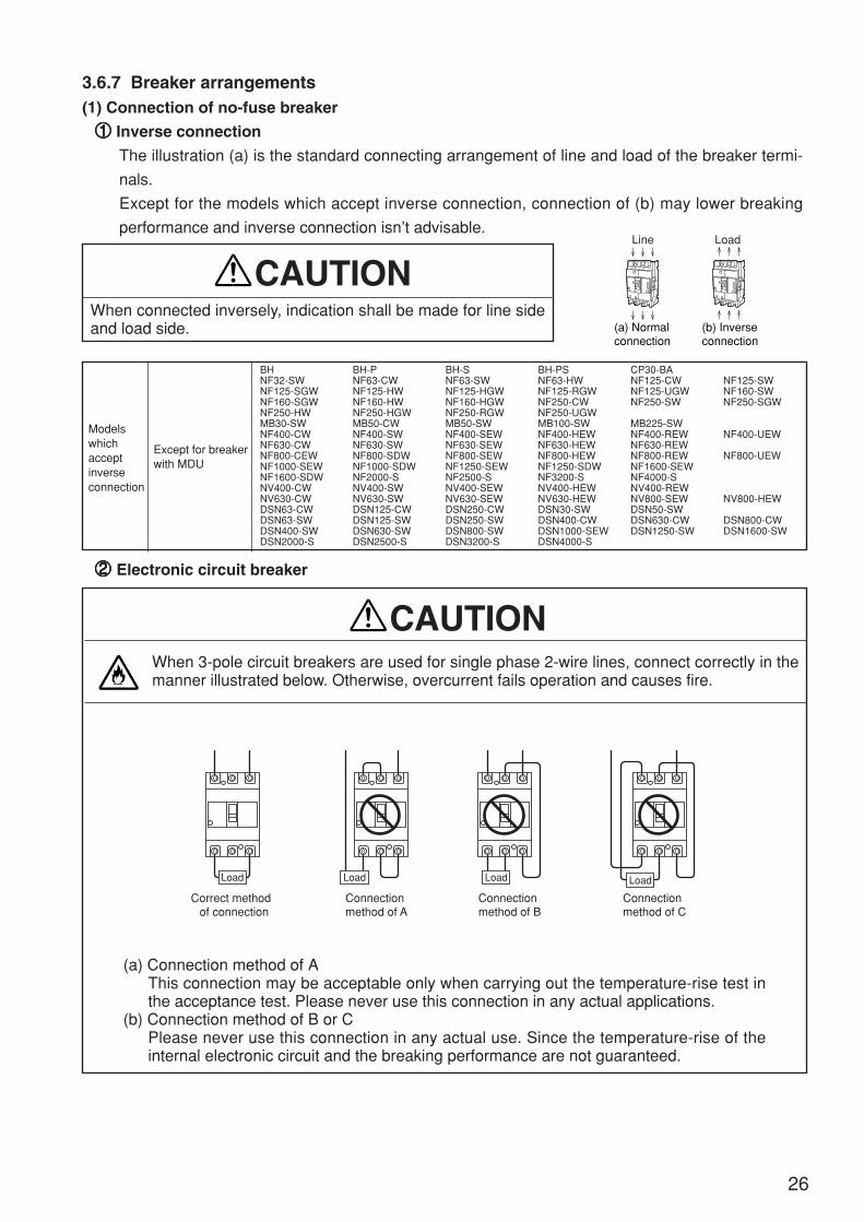
3.6.7 Breaker arrangements(1) Connection of no-fuse breaker
11111 Inverse connection
The illustration (a) is the standard connecting arrangement of line and load of the breaker termi-
nals.
Except for the models which accept inverse connection, connection of (b) may lower breaking
performance and inverse connection isn’t advisable.
When connected inversely, indication shall be made for line sideand load side.
CAUTION
Modelswhichacceptinverseconnection
Except for breakerwith MDU
BH BH-P BH-S BH-PS CP30-BANF32-SW NF63-CW NF63-SW NF63-HW NF125-CW NF125-SWNF125-SGW NF125-HW NF125-HGW NF125-RGW NF125-UGW NF160-SWNF160-SGW NF160-HW NF160-HGW NF250-CW NF250-SW NF250-SGWNF250-HW NF250-HGW NF250-RGW NF250-UGWMB30-SW MB50-CW MB50-SW MB100-SW MB225-SWNF400-CW NF400-SW NF400-SEW NF400-HEW NF400-REW NF400-UEWNF630-CW NF630-SW NF630-SEW NF630-HEW NF630-REWNF800-CEW NF800-SDW NF800-SEW NF800-HEW NF800-REW NF800-UEWNF1000-SEW NF1000-SDW NF1250-SEW NF1250-SDW NF1600-SEWNF1600-SDW NF2000-S NF2500-S NF3200-S NF4000-SNV400-CW NV400-SW NV400-SEW NV400-HEW NV400-REWNV630-CW NV630-SW NV630-SEW NV630-HEW NV800-SEW NV800-HEWDSN63-CW DSN125-CW DSN250-CW DSN30-SW DSN50-SWDSN63-SW DSN125-SW DSN250-SW DSN400-CW DSN630-CW DSN800-CWDSN400-SW DSN630-SW DSN800-SW DSN1000-SEW DSN1250-SW DSN1600-SWDSN2000-S DSN2500-S DSN3200-S DSN4000-S
When 3-pole circuit breakers are used for single phase 2-wire lines, connect correctly in themanner illustrated below. Otherwise, overcurrent fails operation and causes fire.
CAUTION
22222 Electronic circuit breaker
(a) Connection method of AThis connection may be acceptable only when carrying out the temperature-rise test inthe acceptance test. Please never use this connection in any actual applications.
(b) Connection method of B or CPlease never use this connection in any actual use. Since the temperature-rise of theinternal electronic circuit and the breaking performance are not guaranteed.
(a) Normalconnection
ON
Line
(b) Inverseconnection
ON
Load
Correct method of connection
Connectionmethod of A
Load Load
Connectionmethod of B
Load
Connectionmethod of C
Load

27
(2) Connection of earth leakage circuit breaker
1 Connect to a power source suitable for the rating of the circuit breaker. Otherwise, malfunc-tion and failure can result.Application of overvoltage outside the applicable voltage range can cause burning as theearth leakage circuit breaker incorporates electronic circuits.Application of lower voltage than the applicable voltage range also fails operation.
CAUTION
2 Where a circuit breaker is used for 1 phase 3 wire system and 3 phase 4 wire system, besure to connect the neutral wire to the neutral pole of the circuit breaker. Otherwise, opera-tion fails at overcurrent.
(a) For single phase two wire system, refrain from us-
ing neutral pole.
Where a 3-pole earth leakage circuit breaker is used for
single phase 2 wire system, connect to the right and left
poles of the circuit breaker. Using the neutral pole fails op-
eration as the control power for the operation is supplied
through the left and right poles.
(b) Don’t connect in parallel.
Refrain from parallel connection as unnecessary operation
takes place because of loop circuit formed or the leak trip-
ping unit is burnt in some cases. Also refrain from parallel
connection of the earth leakage circuit breaker with a moul-
ded use circuit breaker.
(c) Don’t connect in reverse.
The electronic circuit of ELCB as standard are short time
rating. If used by reverse connection, the electronic circuit
have damaged by continuous voltage of after tripping. There-
fore must not use reverse connection.
The following types are possible to using by reverse con-
nection.Types
NV32-SW, NV63-CW, NV63-SWNV125-CW, NV125-SW, NV250-CW, NV250-SW
NV400-CW, NV400-SW, NV400-SEW, NV400-HEWNV400-REW, NV630-CW, NV630-SW, NV630-SEWNV630-HEW, NV800-SEW, NV800-HEW
Applicable voltage
AC230V
AC230-400-440V
Note 1. Measuring display unit (MDU) breakers are not available.
OFF
240V120V120V
Neutral wireOFF
Neutral wire
Neutral pole
OFF
OFF
OFF OFF
Line sideterminal
Load sideterminal
1φ2W
Power supply
Electroniccircuit

28
(3) Connection of Molded-case circuit breaker with earth leakage current
1 Connect to a power source suitable for the rating of the circuit breaker. Otherwise, mal-function and failure can result.Application of overvoltage outside the applicable voltage range can cause burning as theearth leakage circuit breaker incorporates electronic circuits.Application of lower voltage than the applicable voltage range also fails operation.
CAUTION
2 Where a circuit breaker is used for 1 phase 3 wire system and 3 phase 4 wire system, besure to connect the neutral wire to the neutral pole of the circuit breaker. Otherwise, opera-tion fails at overcurrent.
(a) For single phase two wire system, refrain from us-
ing neutral pole.
Where a 3-pole earth leakage circuit breaker is used for
single phase 2 wire system, connect to the right and left
poles of the circuit breaker. Using the neutral pole fails op-
eration as the control power for the operation is supplied
through the left and right poles.
(b) Don’t connect in parallel.
Refrain from parallel connection as unnecessary operation
takes place because of loop circuit formed or the leak trip-
ping unit is burnt in some cases. Also refrain from parallel
connection of the earth leakage circuit breaker with a moul-
ded use circuit breaker.
(c) Don’t connect in reverse.
Reverse connection should not be used.
OFF
240V120V120V
Neutral wireOFF
Neutral wire
Neutral pole
OFF
OFF
OFF OFF
1φ2W
Power supply
29
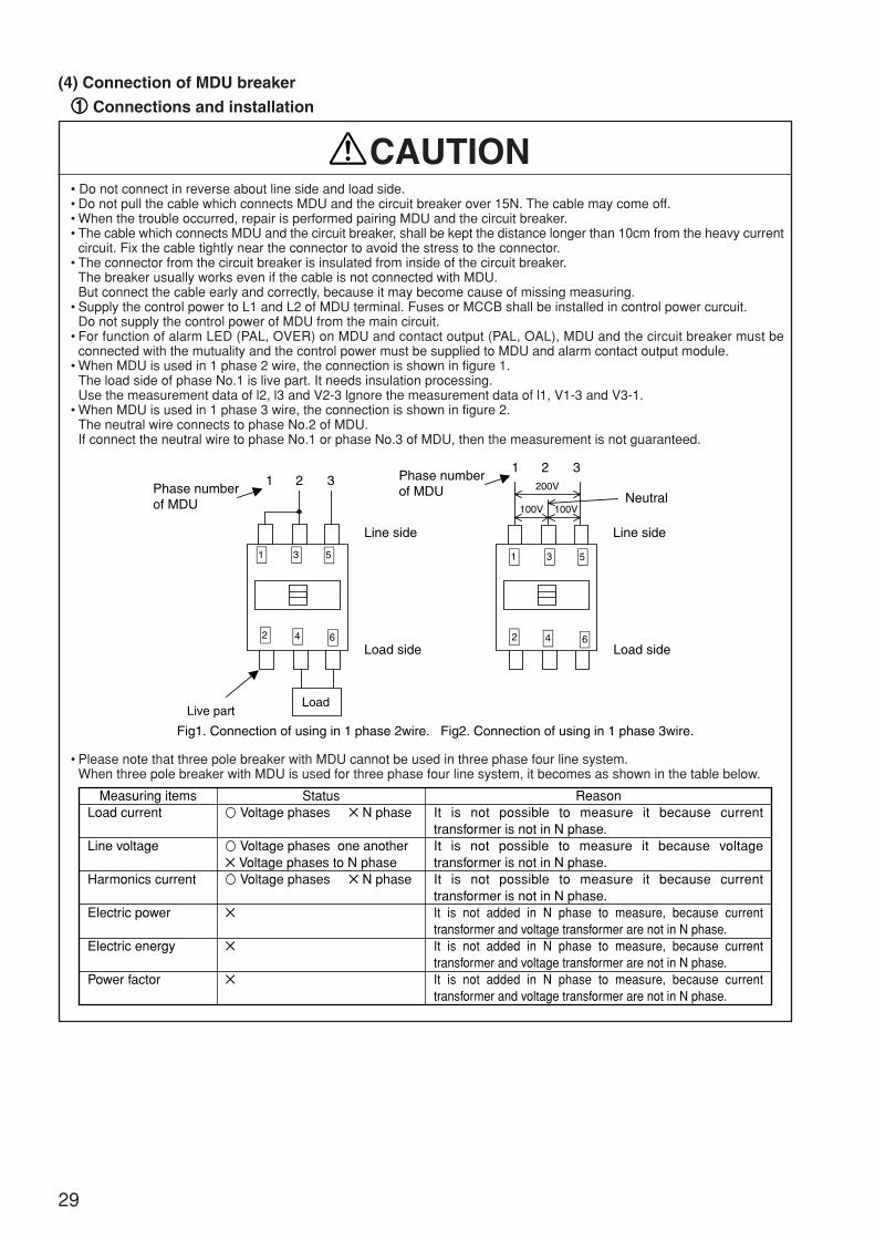
• Do not connect in reverse about line side and load side.• Do not pull the cable which connects MDU and the circuit breaker over 15N. The cable may come off.• When the trouble occurred, repair is performed pairing MDU and the circuit breaker.• The cable which connects MDU and the circuit breaker, shall be kept the distance longer than 10cm from the heavy current
circuit. Fix the cable tightly near the connector to avoid the stress to the connector.• The connector from the circuit breaker is insulated from inside of the circuit breaker.
The breaker usually works even if the cable is not connected with MDU.But connect the cable early and correctly, because it may become cause of missing measuring.
• Supply the control power to L1 and L2 of MDU terminal. Fuses or MCCB shall be installed in control power curcuit.Do not supply the control power of MDU from the main circuit.
• For function of alarm LED (PAL, OVER) on MDU and contact output (PAL, OAL), MDU and the circuit breaker must beconnected with the mutuality and the control power must be supplied to MDU and alarm contact output module.
• When MDU is used in 1 phase 2 wire, the connection is shown in figure 1.The load side of phase No.1 is live part. It needs insulation processing.Use the measurement data of l2, l3 and V2-3 lgnore the measurement data of l1, V1-3 and V3-1.
• When MDU is used in 1 phase 3 wire, the connection is shown in figure 2.The neutral wire connects to phase No.2 of MDU.If connect the neutral wire to phase No.1 or phase No.3 of MDU, then the measurement is not guaranteed.
CAUTION
1 2 31 2 3
Load
Line side
Load side
200V
100V
Line side
100V Neutral
Fig1. Connection of using in 1 phase 2wire. Fig2. Connection of using in 1 phase 3wire.
Live part
Load side
Phase numberof MDU
Phase numberof MDU
1 53
2 4 6
1 53
2 4 6
(4) Connection of MDU breaker
11111 Connections and installation
• Please note that three pole breaker with MDU cannot be used in three phase four line system.When three pole breaker with MDU is used for three phase four line system, it becomes as shown in the table below.
It is not possible to measure it because current transformer is not in N phase. It is not possible to measure it because voltage transformer is not in N phase.It is not possible to measure it because current transformer is not in N phase.It is not added in N phase to measure, because current transformer and voltage transformer are not in N phase.It is not added in N phase to measure, because current transformer and voltage transformer are not in N phase.It is not added in N phase to measure, because current transformer and voltage transformer are not in N phase.
ReasonMeasuring itemsLoad current
Line voltage
Harmonics current
Electric power
Electric energy
Power factor
Status Voltage phases N phase
Voltage phases one another Voltage phases to N phase Voltage phases N phase

30
• The size of wiring MDU is shown as below.
CAUTION
• Tighten the terminal screws with following tightening torque.Tightening torque 0.5 - 0.6 N·mTool minus head screw driver Bit size Thickness 0.6mm Width 3.5mmWire strip length 7mm
• The finish of the wireIn case of single core wire, it can be connected directly to the terminals.In case of twisted core wire, strip the insulation and twist copper wires. Then it can be connected directly to the terminals. Takescare the short circuit by wiring. The solder plating is not allowed.
Following compression pin terminal is recommended.Manufacturer : Phenix contactCross section of wiring 0.25mm2:AI 0.25-6 YE (Catalog NO. 3200179)Cross section of wiring 0.5mm2:AI 0.5-6 WH(Catalog NO.3200687)Terminal for 2 wires 0.5mm2 × 2:AI-TWIN 2 × 0.5-8 WH(Catalog NO.3200933)
Please contact to the manufacturer as for further details.However the length of pin terminal (compression) islonger than 7mm, cut the metal pin as follows.
In case of single connectionIn case of double connection
Twisted core0.14-1.5mm2
0.14-75mm2
Single core0.45-1.2mm2
0.45-0.8mm2
Pin terminalMetal pin
Cut7mm
[ Note of MDU with electric energy accumulated pulse output option ]
• Output line shall be kept the distance longer than 10cm from the heavy current circuit.And maximum wiring distance is less than and including 100m.
• In the case of pulse output connects to the AC, please pay attention to malfunction of receiver by leakage current by earthcapacitance or mutual capacitance between wires.
CAUTION
[ Note of MDU with CC-Link option ]
• Make sure to connect DA, DB, DG and SLD terminals on MDU to CC-Link line with shielded twisted pair cable.When the lived wires are connected to CC-Link terminals, by mistake, it may occur electric shock or fire.Because CC-Link terminals use only low voltage signals.
• The shielded twisted pair cable of CC-Link line shall be kept the distance longer than 10cm from the heavy current circuit.However, it shall be kept the distance longer than 30cm from the heavy current circuit when parallel installation with theheavy current circuit is required.
• The hole cutout of the panel board cannot be done with CC-Link for the breaker-mounting of MDU installation. If the holecutout is done to the panel board, the space in the CC-Link cable wiring makes an useless hole space.
CAUTION
• Following EMC tests are required with IEC60947-2,(i) Radiated radio frequency emission.(ii) Radiated radio frequency electromagnetic field immunity.
• MDU shall be installed in the panel board. It effects not only for safe against electric shock but also to interrupt noiseemission from MDU is confirmed in accordance with following conditions.
Condition 1: (Power distribution board, control panel board)
(i) Power distribution board or control panel board shall be made of conductive materials.(ii) Electrical contact impedance of screwed area between top/bottom plates and enclosure shall be as low as possible
with paint removing.(iii) Internal plate of power distribution board or control panel board shall be also paint removed to reduce the electrical
contact impedance around screwed area.(iv) Power distribution board or control panel board shall be grounded to the earth with a large cable.
Installation in the panel board (EMC directive)

Shield
Paint masked Shielded cable
Metallic clamp
Screw
• Voltage transformers are conncted between the poles on the load side of the circuit breaker.(i) Measurement of insulation resistance
A 1000 volt insulation resistance tester cannot be used with a marks in the table as below.A 500 volt insulation resistance tester shall be used, but measured resistance shows low resistance.
(ii) Withstand voltage testVoltage shall not be applied at the portions with X marks in the table as below.
• The voltage between each terminal must not become DC5V or more when you do the cable check etc. of DA, DB, DG, SLD,and the terminal FG for the CC-Link. It is likely to break down.
CAUTION
Measuring point/test
State of handle
Between live part and earth (except MDU terminal)
Between line and load terminal
Between main circuit and MDU terminal (L1, L2)
Between MDU terminal (L1, L2) and MDU terminal (FG)
Betweendifferent
poles
Line side
Load side
Between left and middle poles
Between middle and right poles
Between left and right poles
Between middle and neutral poles
Between left and middle poles
Between middle and right poles
Between left and right poles
Between middle and neutral poles
Measurement ofInsulation resistance Withstand voltage test
ON
Note1. Connect MDU terminal (L1, L2, 113, 114, DA, DB, DG, SLD and FG) to the earth side.Note2. Connect MDU terminal (113, 114, DA, DB, DG, SLD and FG) to the earth side.Note3. Do not test between MDU terminal (DA, DB, DG and SLD) and MDU terminal (FG).Note4. Connect each MDU terminals (DA, DB, DG, SLD, FG) before you start the test.
OFF ON OFF Test condition
AC2500V 1min
AC2500V 1min
(Note1.)
AC1500V 1min
(Note2.)
In the case ofthese tests,Do not connectMDU terminalto live part orerath
Between main circuit and MDU terminal (113, 114, FG)(With electric energy accumulated pulse output option)
Between main circuit and MDU terminal (DA, DB, DG, SLD, FG)(With CC-Link option)
Between MDU terminal (L1, L2) and MDU terminal (113, 114, FG)(With electric energy accumulated pulse output option)
Between MDU terminal (L1, L2) and MDU terminal (DA, DB, DG, SLD, FG)(With CC-Link option)(Note3.)(Note4.)
Condition 2: (Power line and grounded line)
(i) Connect FG terminal of MDU to PE terminal of MDU (panel) holder plate.Make the earthing point (to be grounded to the earth) near MDU.PE terminal shall be grounded to this point with as short wire as possible.PE terminal effects to reduce the noise of MDU and to shut down the external noise.The grounded wire impedance shall be low.
(ii) Shielded cable earthing(a) When CC-Link cable or power supply cable of MDU are wired from the panel board, use the shielded cable and
ground to the earth near the way out.Secure earthing reduces electromagnetic induction and high frequency noise.
(b) Remove the paint around grounded area to reduce the electrical contact impedance.Metallic clamp is recommended.
• For further details, please read “MELSEC CPU user’s manual” regarding to the wire and cable connection method to PLC.
22222 Measurement of insulation resistance and withstand voltage test
31
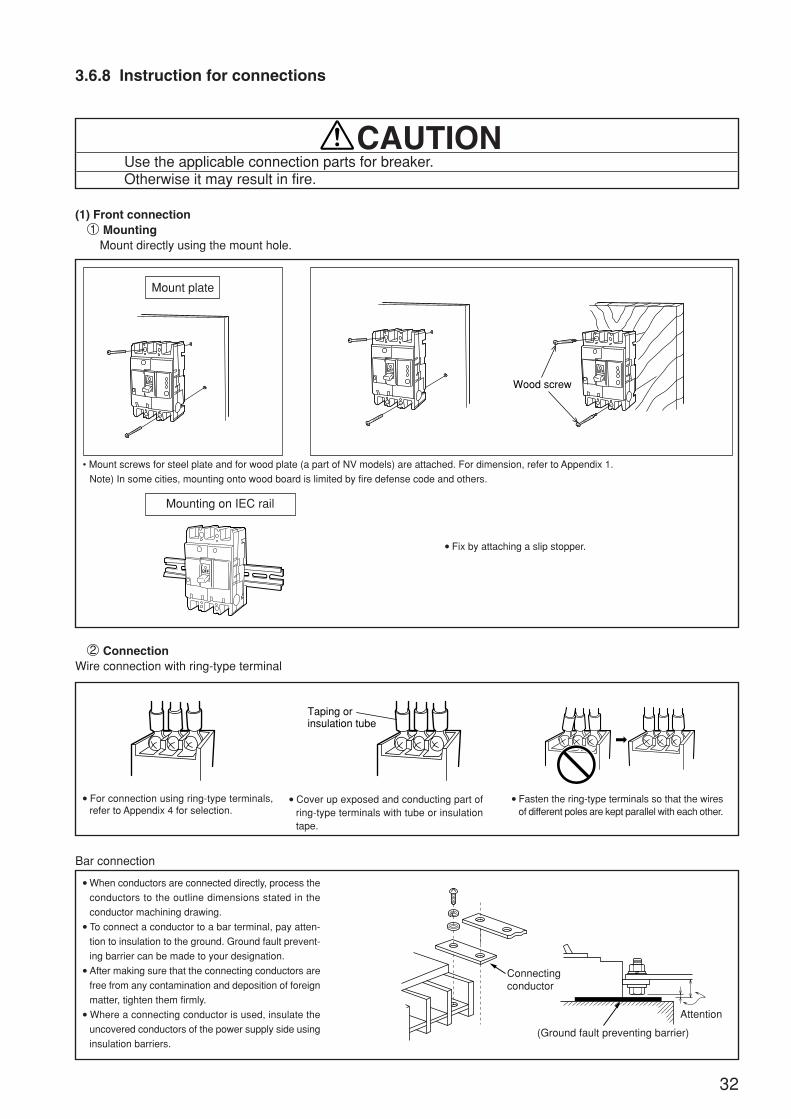
3.6.8 Instruction for connections
Use the applicable connection parts for breaker.Otherwise it may result in fire.
CAUTION
(1) Front connection1 Mounting
Mount directly using the mount hole.
Mount plate
Mounting on IEC rail
• Mount screws for steel plate and for wood plate (a part of NV models) are attached. For dimension, refer to Appendix 1.
Note) In some cities, mounting onto wood board is limited by fire defense code and others.
2 ConnectionWire connection with ring-type terminal
For connection using ring-type terminals,refer to Appendix 4 for selection.
Cover up exposed and conducting part ofring-type terminals with tube or insulationtape.
Fasten the ring-type terminals so that the wiresof different poles are kept parallel with each other.
Bar connection
When conductors are connected directly, process the
conductors to the outline dimensions stated in the
conductor machining drawing. To connect a conductor to a bar terminal, pay atten-
tion to insulation to the ground. Ground fault prevent-
ing barrier can be made to your designation. After making sure that the connecting conductors are
free from any contamination and deposition of foreign
matter, tighten them firmly. Where a connecting conductor is used, insulate the
uncovered conductors of the power supply side using
insulation barriers.
Fix by attaching a slip stopper.
OFF
OFF OFF
Wood screw
OFF
Taping or insulation tube
Connectingconductor
(Ground fault preventing barrier)
Attention
32

Connecting method
33
Clamp connection
When connected directly to a terminal, insert the solid or stranded wire
straight, then fasten the terminal screws.
Ring-type terminals and bars can also be connected. For stranded wires, divided the strands for insertion, then fasten. Re-
tightening is necessary for stranded wires at initial connection in par-
ticular, as stress slackening takes place after fastening. Remove wire insulation to the dimension illustrated below.
Connection with solderless terminal
Crimp after loosening strand of the connec-
tion wire and putting the core wires together.
Regular inspection and retightening are nec-
essary as the wires come loose as time goes. Where stranded wires of fine core such as the
wires for appliances are used, use bar type or
plate type solderless terminals.
Refrain from soldering or binding stranded
wires on the top end.
Fasten carefully so that insulating materials of the
wire is not caught.
3Insulation(a) Insulation barrier
The insulation barriers are used to reinforce insulation between phases of circuit breaker terminals, and to prevent failurecaused by conductive foreign matter and dust. Be sure to use insulation barriers for the models of standard type.To prevent problems, we are ready to mount the insulation barriers on the unit designated by you.
1. For the standard models, be sure to use insulation barriers unless some othereffective means are taken such as terminal cover.
2. To the models for which insulation barriers are packed together in both powersource side and load side, attach them to both sides.
3. To the models for which insulation barriers are packed together in one side only,attach the barriers to arch discharge side (ON side) in either case of regularconnection and inverse connection.
CAUTION
Applicable modelMCCB ELCB Front Rear Flush Plug-in
Packed togetheras the standard
practice
Packed togetheras the standard
practice
Packed togetheras the standard
practice
Packed togetheras the standard
practicePacked togetheras the standard
practice
Packed togetheras the standard
practice
Packed togetheras the standard
practice
—
—
—
—
— — —
—
—
— —
— —
16mm
(One solid wire) (Two solid wires)
(Thick stranded wire )(Connection with ring-type terminal )
OFF
Arc discharge side
Insulation barrier
(Those with circle are optional.)
NF32-SW, NF63-CWMB30-SW, MB50-CWNF125-RGW, NF125-UGW, NF125-CWNF63-ZCW, NF125-ZCWBH(2P, 3P, 40A, 50A)BH-P, BH-S, BH-PS
NF63-SW, NF63-HW, NF125-SW, NF125-HWMB50-SW, MB100-SWNF63-ZSW, NF63-ZHW, NF125-ZSW, NF125-ZHW
NF400-CW, NF400-SW, NF400-SEW, NF400-HEWNF400-REW, NF400-UEW(3P), NF400-ZCW, NF400-ZSWNF400-ZEWNF630-CW, NF630-SW, NF630-SEW, NF630-HEW,NF630-REW, NF630-ZCW, NF630-ZSW NF630-ZEW
NF400-UEP(4P), NF800-CEW, NF800-SEW, NF800-HEW,NF800-REW, NF800-SDW, NF800-UEW, NF800-ZEWNF1000-SEW, NF1250-SEW, NF1250-SDW, NF1250-UR
NF1600-SEW, NF1600-SDW
NV63-CW,NV125-CW, NV125-RW
NV32-SW, NV63-SW, NV63-HWNV125-SW, NV125-HW
NV250-CW, NV250-SW, NV250-HW
NV250-SEW, NV250-HEW, NV250-RW
NV400-CW, NV400-SW, NV400-SEWNV400-HEW, NV400-REWNV630-CW, NV630-SW, NV630-SEWNV630-HEW
NV800-SEW, NV800-HEW
—
NF160-SW, NF160-HW, NF250-CW, NF250-SWNF250-HWNF125-SGW, NF125-HGW, NF125-RGW, NF125-UGWNF160-SGW, NF160-HGWNF250-SGW, NF250-HGW, NF250-RGW, NF250-UGWMB225-SW, NF250-ZCW, NF250-ZSW, NF250-ZHW,NF250-ZEW
Packed togetheras the standard
practice
Packed togetheras the standard
practice

Tapping screw (2pcs.)Tapping screw
Enlargedview ofU-form projection
(Note)
Note. except BTC or PTC
(Note)
Enlargedview ofU-form projection
TCL-2GSW3 TCS-2GSW3
34
4Terminal cover
This is used to avoid exposure of charged parts. Different kinds are prepared for
each application such as large size terminal cover (TC-L), small size terminal
cover (TC-S), transparent terminal cover (TTC), Rear terminal cover (BTC), and
plug-in terminal cover (PTC). Quick set terminal cover
This cover can be attached simply by inserting into the mount hole on the circuit
breaker proper.
To disengage, slip off the cover stop projection by a finger or a screwdriver, then
pull out. (PTC is of screw fix type.)
The models of NF125-SGW/HGW/RGW/UGW, NF160-SGW/HGW, NF250-
SGW/HGW/RGW/UGW are excluded.
When a small size terminal cover (TC-S) is used, cover up the conducting part of the ring-type terminal with insulation tube or by taping but notexceeding surface A.
Small size terminal cover
Surface Alnsulation tube
Wire
Note. No insulation barriers are needed with terminal covers are attached.
Circuit breaker Terminal cover
AB
Ring-type terminal
Bus bar
TC-L & TTC
lnsulator
TC-S
L
L
TC-L & TTC
34.5
34.5
B
25
25
A
29.5
29.5
LTC-S
14.5
13.5
B
5
4.1
A
12.0
11.0
L
Exposed live partsLimited condition
(mm)
NF30-CS, MB30-CS,NV30-CS
NF32-SW,50A frame, 63A frame
other 125A frame
NF125-SGW/HGWNF160-SGW/HGWNF250-SGW/HGWNF125-UGW/RGWNF250-UGW/RGW
50.540 45.5 14.03.5 11.0
NF125-SGW/HGW/RGW/UGW, NF160-SGW/HGW,
NF250-SGW/HGW/RGW/UGW
DSN125-SGW, DSN160-SGW, DSN250-SGW
Mounting
1) Put the U-form projection in the hole of the breaker and push
the terminal cover strongly to fasten it.
(Push the indicated place by the “ ” mark.)(Note)
2) Fix the terminal cover with tapping screws (in 4 positions
with tightening torque 0.6 – 0.8 N·m).
Removing
1) Remove the tapping screws.
2) Push the tip of the U-form projection fully toward the “ ”
mark by the screw driver or a finger tip and pull out the ter-
minal cover toward the “ ” mark.(Note)
40
40
50.5
50.5
45.5
45.5
4.5
3.2
15.0
13.5
12.5
11.0other 160A frame,250A frame
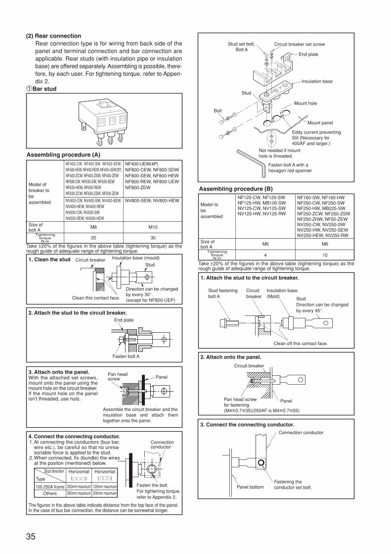
35
(2) Rear connectionRear connection type is for wiring from back side of thepanel and terminal connection and bar connection areapplicable. Rear studs (with insulation pipe or insulationbase) are offered separately. Assembling is possible, there-fore, by each user. For tightening torque, refer to Appen-dix 2.
1Bar stud
Assembling procedure (A)
Assembling procedure (B)
Take ±20% of the figures in the above table (tightening torque) as therough guide of adequate range of tightening torque.
1. Clean the stud
2. Attach the stud to the circuit breaker.
3. Attach onto the panel.With the attached set screws,mount onto the panel using themount hole on the circuit breaker.If the mount hole on the panelisn’t threaded, use nuts.
4. Connect the connecting conductor. 1.At connecting the conductors (bus bar,
wire etc.), be careful so that no unrea-sonable force is applied to the stud.
2.When connected, fix (bundle) the wiresat the positon (mentioned) below.
The figures in the above table indicate distance from the top face of the panel.In the case of bus bar connection, the distance can be somewhat longer.
Model ofbreaker tobeassembled
Size ofbolt A
TighteningtorqueN·m
NF400-CW, NF400-SW, NF400-SEW,NF400-HEW, NF400-REW, NF400-UEW(3P)NF400-ZCW, NF400-ZSW, NF400-ZEWNF630-CW, NF630-SW, NF630-SEWNF630-HEW, NF630-REWNF630-ZCW, NF630-ZSW, NF630-ZEW
NV400-CW, NV400-SW, NV400-SEW,NV400-HEW, NV400-REWNV630-CW, NV630-SWNV630-SEW, NV630-HEW
M8
20
NF400-UEW(4P)NF800-CEW, NF800-SDWNF800-SEW, NF800-HEWNF800-REW, NF800-UEWNF800-ZEW
NV800-SEW, NV800-HEW
M10
30
Model tobeassembled
Size ofbolt A
TighteningtorqueN·m
NF125-CW, NF125-SWNF125-HW, MB100-SWNV125-CW, NV125-SWNV125-HW, NV125-RW
M6
4
NF160-SW, NF160-HWNF250-CW, NF250-SWNF250-HW, MB225-SWNF250-ZCW, NF250-ZSWNF250-ZHW, NF50-ZEWNV250-CW, NV250-SWNV250-HW, NV250-SEWNV250-HEW, NV250-RW
M6
10
Take ±20% of the figures in the above table (tightening torque) as therough guide of adequate range of tightening torque.
1. Attach the stud to the circuit breaker.
2. Attach onto the panel.
3. Connect the connecting conductor.
Stud set bolt, Bolt A
Circuit breaker set screw
End plate
Insulation base
Mount hole
Mount panel
Eddy current preventingSlit (Necessary for400AF and larger.)
Not needed if mounthole is threaded.
Fasten bolt A with ahexagon rod spanner
Stud
Bolt
Circuit breaker lnsulation base (mould)
Stud
Clean this contact face.
Direction can be changedby every 30°.(except for NF800-UEP)
End plate
Fasten bolt A
Pan headscrew Panel
Assemble the circuit breaker and theinsulation base and attach themtogether onto the panel.
Connectionconductor
Fasten the bolt.For tightening torque,refer to Appendix 2.
Circuit breaker
Pan head screwfor fastening.(M40.735)(250AF is M40.755)
Panel
Stud fasteningbolt A
Circuitbreaker
lnsulation base(Mold) Stud
Direction can be changedby every 45°.
Clean off this contact face.
Connection conductor
Fastening theconductor set bolt.Panel bottom100.250A frame
Others
Horizontal( )
200mm maximum350mm maximum
Stud direction
Type
Horizontal( )
120mm maximum200mm maximum
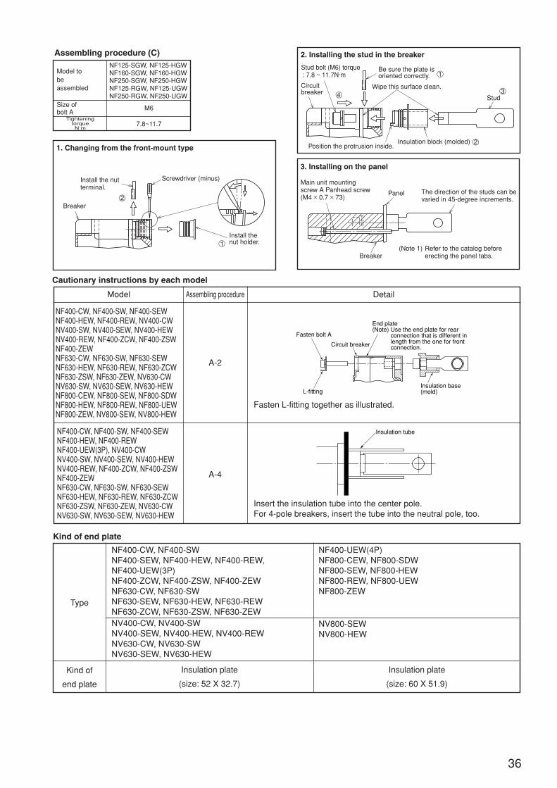
36
Cautionary instructions by each model
Model Assembling procedure Detail
NF400-CW, NF400-SW, NF400-SEWNF400-HEW, NF400-REW, NV400-CWNV400-SW, NV400-SEW, NV400-HEWNV400-REW, NF400-ZCW, NF400-ZSWNF400-ZEWNF630-CW, NF630-SW, NF630-SEWNF630-HEW, NF630-REW, NF630-ZCWNF630-ZSW, NF630-ZEW, NV630-CWNV630-SW, NV630-SEW, NV630-HEWNF800-CEW, NF800-SEW, NF800-SDWNF800-HEW, NF800-REW, NF800-UEWNF800-ZEW, NV800-SEW, NV800-HEW
NF400-CW, NF400-SW, NF400-SEWNF400-HEW, NF400-REWNF400-UEW(3P), NV400-CWNV400-SW, NV400-SEW, NV400-HEWNV400-REW, NF400-ZCW, NF400-ZSWNF400-ZEWNF630-CW, NF630-SW, NF630-SEWNF630-HEW, NF630-REW, NF630-ZCWNF630-ZSW, NF630-ZEW, NV630-CWNV630-SW, NV630-SEW, NV630-HEW
Insert the insulation tube into the center pole.For 4-pole breakers, insert the tube into the neutral pole, too.
A-2
A-4
Fasten L-fitting together as illustrated.
NF400-CW, NF400-SWNF400-SEW, NF400-HEW, NF400-REW,NF400-UEW(3P)NF400-ZCW, NF400-ZSW, NF400-ZEWNF630-CW, NF630-SWNF630-SEW, NF630-HEW, NF630-REWNF630-ZCW, NF630-ZSW, NF630-ZEW
NF400-UEW(4P)NF800-CEW, NF800-SDWNF800-SEW, NF800-HEWNF800-REW, NF800-UEWNF800-ZEW
Kind of end plate
Insulation tube
Fasten bolt A
Circuit breaker
L-fitting
End plate(Note) Use the end plate for rear connection that is different in length from the one for front connection.
Insulation base(mold)
Assembling procedure (C)
Model tobeassembled
Size ofbolt A
TighteningtorqueN·m
NF125-SGW, NF125-HGWNF160-SGW, NF160-HGWNF250-SGW, NF250-HGWNF125-RGW, NF125-UGWNF250-RGW, NF250-UGW
M6
7.8~11.7
2. Installing the stud in the breaker
3. Installing on the panel
1. Changing from the front-mount type
Install the nutterminal.
Breaker
Screwdriver (minus)
Install thenut holder.1
2
Circuitbreaker
Stud bolt (M6) torque : 7.8 ~ 11.7N·m
Be sure the plate isoriented correctly.
Wipe this surface clean.
Stud
Insulation block (molded)Position the protrusion inside.
1
3
2
4
Breaker
The direction of the studs can bevaried in 45-degree increments.
Panel
Main unit mountingscrew A Panhead screw(M4 × 0.7 × 73)
Refer to the catalog beforeerecting the panel tabs.
(Note 1)
Type
Kind of
end plate
NV400-CW, NV400-SWNV400-SEW, NV400-HEW, NV400-REWNV630-CW, NV630-SWNV630-SEW, NV630-HEW
Insulation plate
(size: 52 X 32.7)
Insulation plate
(size: 60 X 51.9)
NV800-SEWNV800-HEW

37
1Screw stud connection
Assembling procedure (A)
1. Attach the stud onto the circuit breaker.
2. Mount onto the panel.(Note)
Tap the panel referringto the catalog.
3. Connect the connection conductor.
Model to beassembled
NF30-CS, MB30-CS, NV30-CSNF32-SW, NF63-CW, NF63-SW, NF63-HWMB30-SW, MB50-CW, MB50-SWNV32-SW, NV63-CW, NV63-SW, NV63-HWNF63-ZCW, NF-ZSW, NF63-ZHW
Circuit breaker
PanelPan head screw for fastening(M40.735)
Connectionconductor
Washer(Brass tip plated)
Nut B
Nut C(Brass, tin plated)
Fasten nut B(Note)Hold nut C with a wrench.Be careful so as not toapply unreasonable forceto the stud.
Tightening torque for screw stud
Type (Ampere frame)
30A frame
63A frame1 <M4> 2 <M6>
Tightening torque N·m
Stud fastening screw A<Nominal diameter of screw>
Conductor fastening nut B<Nominal diameter of screw>
Stud fasteningscrew A Circuit
breaker
Insulationbase(Mould)
Nut Cwasher
Springwasher
Conductorfasteningnut B
Screw BClean this contact face.
10cm
20N • m
200N (20kg)
Generally, about 20kg poweris generated by arm. So,tightening torque comes to20N • m by grip-ping illustrated position.
~
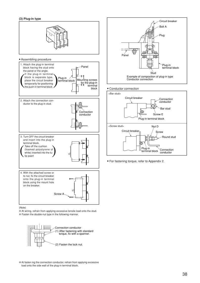
38
(3) Plug-in type
Assembling procedure
1. Attach the plug-in terminalblock having the stud ontothe panel or the angle.
If the plug-in terminalblock is separate type,place the circuit breakertemporarily for positioningthe push-in terminal block.
2. Attach the connection con-ductor to the plug-in stud.
3. Turn OFF the circuit breakerand insert into the plug-interminal block.
Take off the cushion(foamed polystyrene ofwhite) inserted into the tu-lip paart
4. With the attached screw orto nut, fix the circuit breakeronto the plug-in terminalblock using the mount holeon the breaker.
(Note) At wiring, refrain from applying excessive tensile load onto the stud. Fasten the double-nut type in the following manner.
At fasten ing the connection conductor, refrain from applying excessiveload onto the side wall of the plug-in terminal block.
Conductor connection
For fastening torque, refer to Appendix 2.
<Bar stud>
<Screw stud>
Plug-interminal block
Panel
Mounting screwsfor the plug-in
terminalblock
Connectionconductor
Screw A
Connection conductor(1) After fastening with standard torque, fix with a spanner.
(2) Fasten the lock nut.
Circuit breaker
Bolt A
Plug
Panel
Plug-interminal block
StudExample of composition of plug-in typeConductor connection
Circuit breaker Connectionconductor
Bar stud
Screw E
Plug-in terminal block
Circuit breaker
Plug-interminal block
Nut D
Screw
Round stud
Connectionconductor
( )
( )
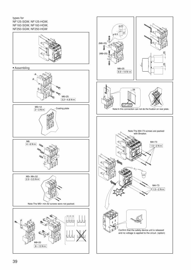
39
types forNF125-SGW, NF125-HGW,NF160-SGW, NF160-HGW,NF250-SGW, NF250-HGW
Assembling
3.2~4.8 N·mM6×25
Coating plate2~3 N·mM5×12
4~6 N·mM6
2.5~3.5 N·mM5× Min.52
Note:The M5× min.52 screws were not packed.
M8×20
8~13 N·m
M8×259.5~14 N・m
10
≦23
φ8.5
(M8×25)
(M8×25)
2626
Note:In this connection can not do the fixation on rear plate.
58
CUT OFF
Note:The M4×73 screws are packed with Breaker.
Confirm that the safety device unit is released and no voltage is applied to the circuit. (option)
LN212A943
M4×73
1.5~2 N·m
M4×73
1.5~2 N·m
DUST
TRIP!
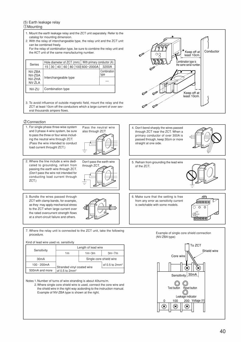
1. Mount the earth leakage relay and the ZCT unit separately. Refer to thecatalog for mounting dimension.
2. With the relay of interchangeable type, the relay unit and the ZCT unitcan be combined freely.For the relay of combination type, be sure to combine the relay unit andthe ACT unit of the same manufacturing number.
3. To avoid influence of outside magnetic field, mount the relay and theZCT at least 10cm off the conductors which a large current of over sev-eral thousands ampere flows.
Interchangeable type
Combination type
To ZCT
Core wire
Shield wire
Sensitivity 30mA
Reset button
Leakage indicator
Test button
0 100 200 Voltage (V)
With primary conductor (A)
7. Where the relay unit is connected to the ZCT unit, take the followingprocedure.
Kind of lead wire used vs. sensitivity
Notes 1.Number of turns of wire stranding is about 40turns/m.2.Where single core shield wire is used, connect the core wire and
the shield wire in the right way acdording to the instruction manual.Example of NV-ZBA type is shown at the right.
40
(5) Earth leakage relay1Mounting
Series
NV-ZBANV-ZSANV-ZHANV-ZLA
NV-ZU
Hole diameter of ZCT (mm)15 30 40 60 80 100 600~2000A 3200A
—
1. For single phase three-wise systemand 3 phase 4-wire system, be sureto pass the three or four wires includ-ing the neutral wire through ZCT.(Pass the wire intended to conductload current throught ZCT.)
2Connection
2. Where the line include a wire dedi-cated to grounding, refrain frompassing the earth wire through ZCT.(Don’t pass the wire not intended forconducting load current throughZCT.)
Pass the neutral wirealso through ZCT
Don’t pass the earth wirethrough ZCT.
3. Bundle the wires passed throughZCT with clamp bands, for example,as they may apply mechanical stressto the ZCT when large current overthe rated overcurrent strength flowsat a short-circuit failure and others.
4. Don’t bend sharply the wires passedthrough ZCT near the ZCT. When aprimary conductor of over 300A ispassed through, keep 30cm or morestraight at one side.
5. Refrain from grounding the lead wireof the ZCT.
6. Make sure that the setting is freefrom any error as sensitivity currentis switchable with some models.
Example of single core shield connection(NV-ZBA type)
30mA
100 · 200mA
500mA and more
SensitivityLength of lead wire
1m 1m~3m 3m~7m
Single core shield wire
of 0.5 to 2mm2
Stranded vinyl coated wireof 0.5 to 2mm2
0.2
0.51A
Keep off atleast 10cm.
Keep off atleast 10cm.
Conductor
Combination type isthe same serial number.
Combinationtype
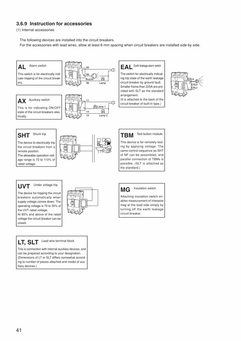
41
3.6.9 Instruction for accessories(1) Internal accessories
The following devices are installed into the circuit breakers.For the accessories with lead wires, allow at least 8 mm spacing when circuit breakers are installed side by side.
SHT Shunt trip
The device to electrically tripthe circuit breakers from aremote position.The allowable operation volt-age range is 70 to 110% ofrated voltage.
AX Auxiliary switch
This is for indicating ON/OFFstate of the circuit breakers elec-trically.
AL Alarm switch
This switch is for electrically indi-cate tripping of the circuit break-ers.
UVT Under voltage trip
The device for tripping the circuitbreakers automatically whensupply voltage comes down. Theoperating voltage is 70 to 35% ofthe UVT rated voltage.At 85% and above of the ratedvoltage the circuit breaker can becosed.
LT, SLT Lead wire terminal block
This is connection with internal auxiliary devices, andcan be prepared according to your designation.(Dimensions of LT or SLT differs somewhat accord-ing to number of pieces attached and model of aux-iliary devices.)
TBM Test button module
This device is for remotely test-ing by applying voltage. Thesame control sequence as SHTof NF can be assembled, andparallel connection of TBMs ispossible. (SLT is attached asthe standard.)
MG Insulation switch
Attaching insulation switch en-ables measurement of interpolemeg at the load side simply byturning off the earth leakagecircuit breaker.
Lamp
98
Buzzer
95
96
ON
OFF
Lamp 2
14
12
11
Lamp 1
OFF
ON
OFF
ON
OFF
ON
EALbEALc
EALa
EAL Earth leakage alarm switch
The switch for electrically indicat-ing trip state of the earth leakagecircuit breaker by ground fault.Smaller frame than 225A are pro-vided with SLT as the standardarrangement.(It is attached to the back of thecircuit breaker of built-in type.)
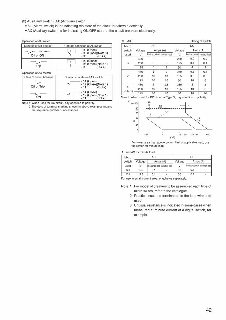
Induction load
-
-
125
125
Resistance load
0.1
0.1
42
(2) AL (Alarm switch), AX (Auxiliary switch) AL (Alarm switch) is for indicating trip state of the circuit breakers electrically. AX (Auxiliary switch) is for indicating ON/OFF state of the circuit breakers electrically.
State of circuit breaker Contact condition of AL switch
State of circuit breaker Contact condition of AX switch
Operation of AL switch
Operation of AX switch
Note 1.When used for DC circuit, pay attention to polarity.2.The dots of terminal marking shown in above examples means
the sequence number of accessories.
ACMicro
switch
used
Amps (A)
AL • AX Rating of switch
S
V
X
(Note,1)
DC
Amps (A)Voltage
(V)
460
250
125
460
250
125
460
250
125
Resistance load
-
3
5
5
10
10
5
10
10
Induction load
-
2
3
2
10
10
2.5
10
10
Voltage
(V)
250
125
30
250
125
30
250
125
30
Resistance load
0.2
0.4
4
0.3
0.6
10
5
10
10
Induction load
0.2
0.4
3
0.3
0.6
6
3
6
10Note 1.When used for DC circuit of Type X, pay attention to polarity.
2.
ACMicro
switch
used
Amps (A)
AL and AX for minute load
SB
VB
DC
Amps (A)Voltage
(V)
Voltage
(V)
30
30
Resistance load
0.1
0.1
Induction load
-
-
For use in small current area, enquire us separately.
Note 1. For model of breakers to be assembled each type ofmicro switch, refer to the catalogue.
2. Practice insulated termination to the lead wires notused.
3. Unusual resistance is indicated in some cases whenmeasured at minute current of a digital switch, forexample.
For lower area than above bottom limit of applicable load, usethe switch for minute load.
Off or ON
Trip
· 98 (Open) · 96 (Close)(Note.1) · 95 (DC +)
· 98 (Close) · 96 (Open)(Note.1) · 95 (DC +)
Off or Trip
ON
· 14 (Open) · 12 (Close)(Note.1) · 11 (DC +)
· 14 (Close) · 12 (Open)(Note.1) · 11 (DC +)
AC
SV
SBVB
AC:DC
12510060
30(V)
(mA)
10
5
0.67 1 4 26 50 100 160 600
DC
X
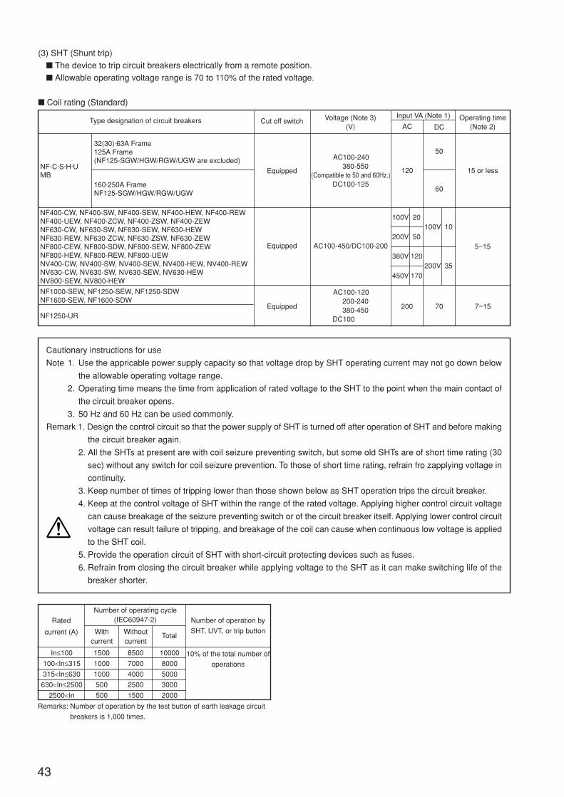
43
(3) SHT (Shunt trip)
The device to trip circuit breakers electrically from a remote position.
Allowable operating voltage range is 70 to 110% of the rated voltage.
Coil rating (Standard)
NF-C·S·H·UMB
Type designation of circuit breakers Cut off switch Voltage (Note 3)(V)
Equipped
Equipped
Equipped
AC100-120200-240380-450
DC100
AC100-450/DC100-200
AC100-240380-550
(Compatible to 50 and 60Hz.)DC100-125
Input VA (Note 1)
AC DCOperating time
(Note 2)
15 or less120
50
60
10
70200 7~15
100V 20
5~15
Cautionary instructions for use
Note 1. Use the appricable power supply capacity so that voltage drop by SHT operating current may not go down below
the allowable operating voltage range.
2. Operating time means the time from application of rated voltage to the SHT to the point when the main contact of
the circuit breaker opens.
3. 50 Hz and 60 Hz can be used commonly.
Remark 1. Design the control circuit so that the power supply of SHT is turned off after operation of SHT and before making
the circuit breaker again.
2. All the SHTs at present are with coil seizure preventing switch, but some old SHTs are of short time rating (30
sec) without any switch for coil seizure prevention. To those of short time rating, refrain fro zapplying voltage in
continuity.
3. Keep number of times of tripping lower than those shown below as SHT operation trips the circuit breaker.
4. Keep at the control voltage of SHT within the range of the rated voltage. Applying higher control circuit voltage
can cause breakage of the seizure preventing switch or of the circuit breaker itself. Applying lower control circuit
voltage can result failure of tripping, and breakage of the coil can cause when continuous low voltage is applied
to the SHT coil.
5. Provide the operation circuit of SHT with short-circuit protecting devices such as fuses.
6. Refrain from closing the circuit breaker while applying voltage to the SHT as it can make switching life of the
breaker shorter.
NF400-CW, NF400-SW, NF400-SEW, NF400-HEW, NF400-REWNF400-UEW, NF400-ZCW, NF400-ZSW, NF400-ZEWNF630-CW, NF630-SW, NF630-SEW, NF630-HEWNF630-REW, NF630-ZCW, NF630-ZSW, NF630-ZEWNF800-CEW, NF800-SDW, NF800-SEW, NF800-ZEWNF800-HEW, NF800-REW, NF800-UEWNV400-CW, NV400-SW, NV400-SEW, NV400-HEW, NV400-REWNV630-CW, NV630-SW, NV630-SEW, NV630-HEWNV800-SEW, NV800-HEW
NF1000-SEW, NF1250-SEW, NF1250-SDWNF1600-SEW, NF1600-SDW
NF1250-UR
32(30)·63A Frame125A Frame(NF125-SGW/HGW/RGW/UGW are excluded)
160·250A FrameNF125-SGW/HGW/RGW/UGW
Remarks: Number of operation by the test button of earth leakage circuit
breakers is 1,000 times.
Rated
current (A) Withcurrent
Withoutcurrent
Total
Number of operating cycle(IEC60947-2)
In≤100
100<In≤315
315<In≤630
630<In≤2500
2500<In
1500
1000
1000
500
500
8500
7000
4000
2500
1500
10000
8000
5000
3000
2000
Number of operation by
SHT, UVT, or trip button
10% of the total number of
operations
100V
35200V
200V 50
380V 120
450V 170
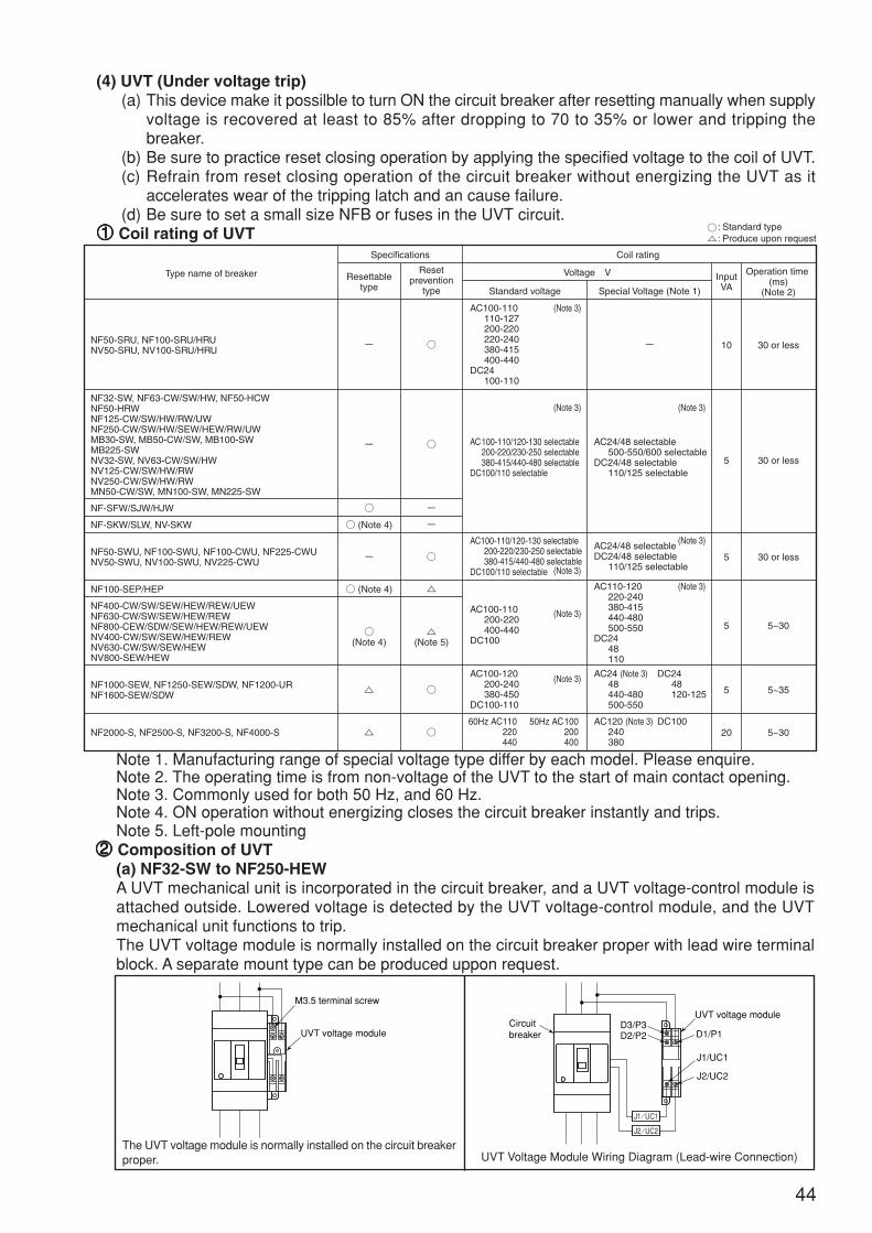
44
(4) UVT (Under voltage trip)(a) This device make it possilble to turn ON the circuit breaker after resetting manually when supply
voltage is recovered at least to 85% after dropping to 70 to 35% or lower and tripping thebreaker.
(b) Be sure to practice reset closing operation by applying the specified voltage to the coil of UVT.(c) Refrain from reset closing operation of the circuit breaker without energizing the UVT as it
accelerates wear of the tripping latch and an cause failure.(d) Be sure to set a small size NFB or fuses in the UVT circuit.
11111 Coil rating of UVT
AC100-110/120-130 selectable200-220/230-250 selectable380-415/440-480 selectable
DC100/110 selectable
AC100-110110-127200-220220-240380-415400-440
DC24100-110
(Note 3)
(Note 3)
AC24/48 selectable500-550/600 selectable
DC24/48 selectable110/125 selectable
(Note 3)
AC100-110200-220400-440
DC100
(Note 3)
AC110-120220-240380-415440-480500-550
DC2448110
(Note 3)
50Hz AC100200400
DC2448120-125
DC100
AC100-120200-240380-450
DC100-110
(Note 3) AC24 (Note 3)48440-480500-550
AC100-110/120-130 selectable200-220/230-250 selectable380-415/440-480 selectable
DC100/110 selectable (Note 3)
: Produce upon request: Standard type
60Hz AC110220440
AC120 (Note 3)240380
(Note 3)AC24/48 selectableDC24/48 selectable
110/125 selectable
NF50-SRU, NF100-SRU/HRUNV50-SRU, NV100-SRU/HRU
NF32-SW, NF63-CW/SW/HW, NF50-HCWNF50-HRWNF125-CW/SW/HW/RW/UWNF250-CW/SW/HW/SEW/HEW/RW/UWMB30-SW, MB50-CW/SW, MB100-SWMB225-SWNV32-SW, NV63-CW/SW/HWNV125-CW/SW/HW/RWNV250-CW/SW/HW/RWMN50-CW/SW, MN100-SW, MN225-SW
NF-SFW/SJW/HJW
NF-SKW/SLW, NV-SKW
NF100-SEP/HEP
NF50-SWU, NF100-SWU, NF100-CWU, NF225-CWUNV50-SWU, NV100-SWU, NV225-CWU
NF400-CW/SW/SEW/HEW/REW/UEWNF630-CW/SW/SEW/HEW/REWNF800-CEW/SDW/SEW/HEW/REW/UEWNV400-CW/SW/SEW/HEW/REWNV630-CW/SW/SEW/HEWNV800-SEW/HEW
NF1000-SEW, NF1250-SEW/SDW, NF1200-URNF1600-SEW/SDW
NF2000-S, NF2500-S, NF3200-S, NF4000-S
- -
-
(Note 4)
-
(Note 4)
(Note 4)
Resettable type
Reset prevention
type
-
-
(Note 5)
10 30 or less
5 30 or less
5 30 or less
5 5~30
5 5~35
20 5~30
Type name of breaker
Specifications Coil rating
Voltage V
Standard voltage Special Voltage (Note 1)
InputVA
Operation time (ms)
(Note 2)
Note 1. Manufacturing range of special voltage type differ by each model. Please enquire.Note 2. The operating time is from non-voltage of the UVT to the start of main contact opening.Note 3. Commonly used for both 50 Hz, and 60 Hz.Note 4. ON operation without energizing closes the circuit breaker instantly and trips.Note 5. Left-pole mounting
22222 Composition of UVT(a) NF32-SW to NF250-HEWA UVT mechanical unit is incorporated in the circuit breaker, and a UVT voltage-control module isattached outside. Lowered voltage is detected by the UVT voltage-control module, and the UVTmechanical unit functions to trip.The UVT voltage module is normally installed on the circuit breaker proper with lead wire terminalblock. A separate mount type can be produced uppon request.
UVT voltage module
M3.5 terminal screw
Circuitbreaker
UVT voltage module
D1/P1
J1/UC1
J2/UC2
D3/P3D2/P2
J1/UC1
J2/UC2
The UVT voltage module is normally installed on the circuit breakerproper. UVT Voltage Module Wiring Diagram (Lead-wire Connection)
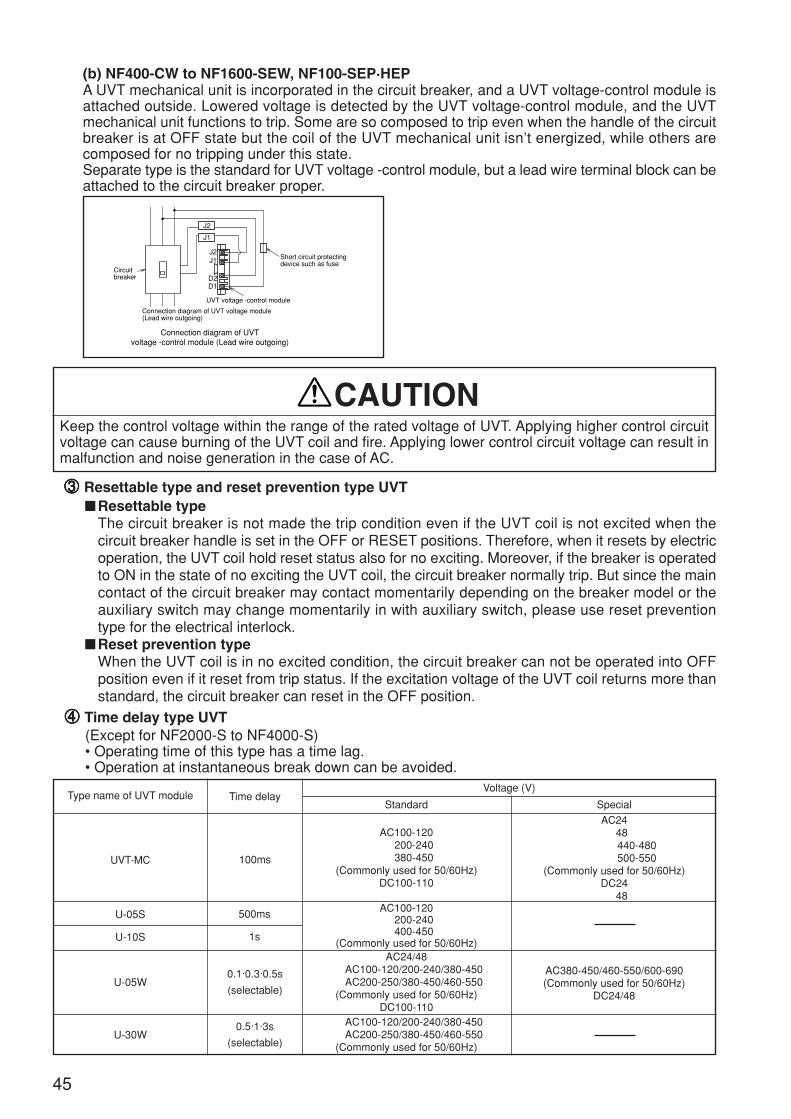
45
Voltage (V)
Standard SpecialType name of UVT module
UVT-MC
U-05S
U-10S
100ms
500ms
1s
Time delay
AC100-120200-240380-450
(Commonly used for 50/60Hz)DC100-110
AC2448440-480500-550
(Commonly used for 50/60Hz)DC24
48AC100-120
200-240400-450
(Commonly used for 50/60Hz)
44444 Time delay type UVT(Except for NF2000-S to NF4000-S)• Operating time of this type has a time lag.• Operation at instantaneous break down can be avoided.
U-05W0.1·0.3·0.5s
(selectable)
AC24/48AC100-120/200-240/380-450AC200-250/380-450/460-550
(Commonly used for 50/60Hz)DC100-110
AC380-450/460-550/600-690(Commonly used for 50/60Hz)
DC24/48
U-30W0.5·1·3s
(selectable)
AC100-120/200-240/380-450AC200-250/380-450/460-550
(Commonly used for 50/60Hz)
Keep the control voltage within the range of the rated voltage of UVT. Applying higher control circuitvoltage can cause burning of the UVT coil and fire. Applying lower control circuit voltage can result inmalfunction and noise generation in the case of AC.
CAUTION
Circuitbreaker
Short circuit protectingdevice such as fuse
UVT voltage -control module
D2
J2
J1
J2J1
D1
Connection diagram of UVT voltage module(Lead wire outgoing)
Connection diagram of UVTvoltage -control module (Lead wire outgoing)
(b) NF400-CW to NF1600-SEW, NF100-SEP·HEPA UVT mechanical unit is incorporated in the circuit breaker, and a UVT voltage-control module isattached outside. Lowered voltage is detected by the UVT voltage-control module, and the UVTmechanical unit functions to trip. Some are so composed to trip even when the handle of the circuitbreaker is at OFF state but the coil of the UVT mechanical unit isn’t energized, while others arecomposed for no tripping under this state.Separate type is the standard for UVT voltage -control module, but a lead wire terminal block can beattached to the circuit breaker proper.
33333 Resettable type and reset prevention type UVTResettable type
The circuit breaker is not made the trip condition even if the UVT coil is not excited when thecircuit breaker handle is set in the OFF or RESET positions. Therefore, when it resets by electricoperation, the UVT coil hold reset status also for no exciting. Moreover, if the breaker is operatedto ON in the state of no exciting the UVT coil, the circuit breaker normally trip. But since the maincontact of the circuit breaker may contact momentarily depending on the breaker model or theauxiliary switch may change momentarily in with auxiliary switch, please use reset preventiontype for the electrical interlock.
Reset prevention typeWhen the UVT coil is in no excited condition, the circuit breaker can not be operated into OFFposition even if it reset from trip status. If the excitation voltage of the UVT coil returns more thanstandard, the circuit breaker can reset in the OFF position.
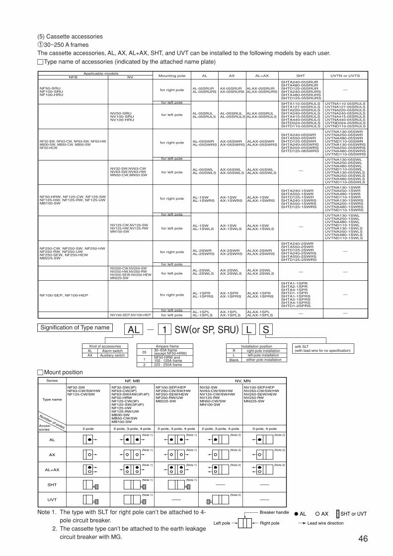
46
(5) Cassette accessories130~250 A framesThe cassette accessories, AL, AX, AL+AX, SHT, and UVT can be installed to the following models by each user.
Type name of accessories (indicated by the attached name plate)
Applicable modelsMounting pole
for right pole
for right pole
for left pole
for left pole
for left pole
for left pole
for right pole
for left pole
for left pole
for right pole
for left pole
for left pole
for right pole
for left pole
for left pole
AL AX AL+AX SHT UVTN or UVTSNVNFB
NF32-SW, NF63-CW, NF63-SW, NF63-HWMB30-SW, MB50-CW, MB50-SWNF50-HCW
NF50-SRUNF100-SRUNF100-HRU
AL-05SWRAL-05SWRS
AX-05SWRAX-05SWRS
ALAX-05SWRALAX-05SWRS
ALAX-05SRURALAX-05SRURS
AX-05SRURAX-05SRURS
AL-05SRURAL-05SRURS
ALAX-05SRULALAX-05SRULS
AL-05SRULAL-05SRULS
AL-05SRULAL-05SRULS
AL-05SWLAL-05SWLS
AX-05SWLAX-05SWLS
ALAX-05SWLALAX-05SWLS
AL-1SWAL-1SWRS
AX-1SWAX-1SWRS
ALAX-1SWALAX-1SWRS
AL-1SWAL-1SWLS
AX-1SWAX-1SWLS
ALAX-1SWALAX-1SWLS
AL-2SWRAL-2SWRS
AX-2SWRAX-2SWRS
ALAX-2SWRALAX-2SWRS
AL-2SWLAL-2SWLS
AX-2SWLAX-2SWLS
ALAX-2SWLALAX-2SWLS
AL-1SPRAL-1SPRS
AX-1SPRAX-1SPRS
ALAX-1SPRALAX-1SPRS
AL-1SPLAL-1SPLS
AX-1SPLAX-1SPLS
ALAX-1SPLALAX-1SPLS
NV32-SW,NV63-CWNV63-SW,NV63-HWMN50-CW,MN50-SW
NV50-SRUNV100-SRUNV100-HRU
SHTA240-05SWRSHTA550-05SWRSHTD125-05SWRSHTA240-05SWRSSHTA550-05SWRSSHTD125-06SWRS
UVTNA130-05SWRUVTNA250-05SWRUVTNA480-05SWRUVTND110-05SWRUVTNA130-05SWRSUVTNA250-05SWRSUVTNA480-05SWRSUVTND110-05SWRS
SHTA240-05SRURSHTA480-05SRURSHTD125-05SRURSHTA240-05SRURSSHTA480-05SRURSSHTD125-05SRURS
SHTA110-05SRULSSHTA127-05SRULSSHTA220-05SRULSSHTA240-05SRULSSHTA415-05SRULSSHTA440-05SRULSSHTD024-05SRULSSHTD110-05SRULS
UVTNA110-05SRULSUVTNA127-05SRULSUVTNA220-05SRULSUVTNA240-05SRULSUVTNA415-05SRULSUVTNA440-05SRULSUVTND024-05SRULSUVTND110-05SRULS
UVTNA130-05SWLUVTNA250-05SWLUVTNA480-05SWLUVTND110-05SWLUVTNA130-05SWLSUVTNA250-05SWLSUVTNA480-05SWLSUVTND110-05SWLS
UVTNA130-1SWRUVTNA250-1SWRUVTNA480-1SWRUVTND110-1SWRUVTNA130-1SWRSUVTNA250-1SWRSUVTNA480-1SWRSUVTND110-1SWRS
UVTNA130-1SWLUVTNA250-1SWLUVTNA480-1SWLUVTND110-1SWLUVTNA130-1SWLSUVTNA250-1SWLSUVTNA480-1SWLSUVTND110-1SWLS
SHTA240-1SWRSHTA550-1SWRSHTD125-1SWRSHTA240-1SWRSSHTA550-1SWRSSHTD125-1SWRS
SHTA240-2SWRSHTA550-2SWRSHTD125-2SWRSHTA240-2SWRSSHTA550-2SWRSSHTD125-2SWRS
SHTA1-1SPRSHTA2-1SPRSHTA4-1SPRSHTD1-1SPRSHTA1-1SPRSSHTA2-1SPRSSHTA4-1SPRSSHTD1-2SPRS
NV250-CW,NV250-SWNV250-HW,NV250-RWNV250-SEW,NV250-HEWMN225-SW
NV125-CW,NV125-SWNV125-HW,NV125-RWMN100-SW
NV100-SEP,NV100-HEP
NF50-HRW, NF125-CW, NF125-SWNF125-HW, NF125-RW, NF125-UWMB100-SW
NF250-CW, NF250-SW, NF250-HWNF250-RW, NF250-UWNF250-SEW, NF250-HEWMB225-SW
NF100-SEP, NF100-HEP
—
—
—
— —
—
—
—
—
Signification of Type name
Kind of accessoriesAlarm switch
Auxiliary switchALAX
Installation positionright-pole installation left-pole installation
either pole installation
R
BlankL
AL 1 L SSW(or SP, SRU)
Ampare frame30~63A frame(except NF50-HRW)NF50-HRW and 100 · 125A frame 225 · 250A frame
05
1
2
with SLT(with lead wire for no specification)
Left pole Right pole
Breaker handle
Lead wire direction
AL AX SHT or UVT
Series
AL
AX
AL+AX
SHT
UVT
NF, MB NV, MN
Type name
Acces-sories
Number of poles
NF32-SWNF63-CW/SW/HWNF125-CW/SW
NV32-SWNV63-CW/SW/HWNV125-CW/SW/HWNV125-RWMN50-CW/SWMN100-SW
NF32-SW(3P)NF63-CW(3P)NF63-SW/HW(3P,4P)NF50-HRWNF125-CW(3P)NF125-SW(3P,4P)NF125-HWNF125-RW/UWMB30-SWMB50-CW/SWMB100-SW
NV100-SEP/HEPNV250-CW/SW/HWNV250-SEW/HEWNV250-RWMN225-SW
NF100-SEP/HEPNF250-CW/SW/HWNF250-SEW/HEWNF250-RW/UWMB225-SW
2-pole 2-pole, 3-pole, 4-pole
(Note 1)
(Note 1)
(Note 1)
(Note 1)
(Note 1)
(Note 1)
(Note 1)
(Note 1)
(Note 1)
(Note 2)
(Note 2)
(Note 2)
(Note 2)
(Note 2)
(Note 2)
(Note 2)
2-pole, 3-pole, 4-pole 2-pole, 3-pole, 4-pole 3-pole, 4-pole
—
— —
—
Mount position
Note 1. The type with SLT for right pole can’t be attached to 4-pole circuit breaker.
2. The cassette type can’t be attached to the earth leakagecircuit breaker with MG.
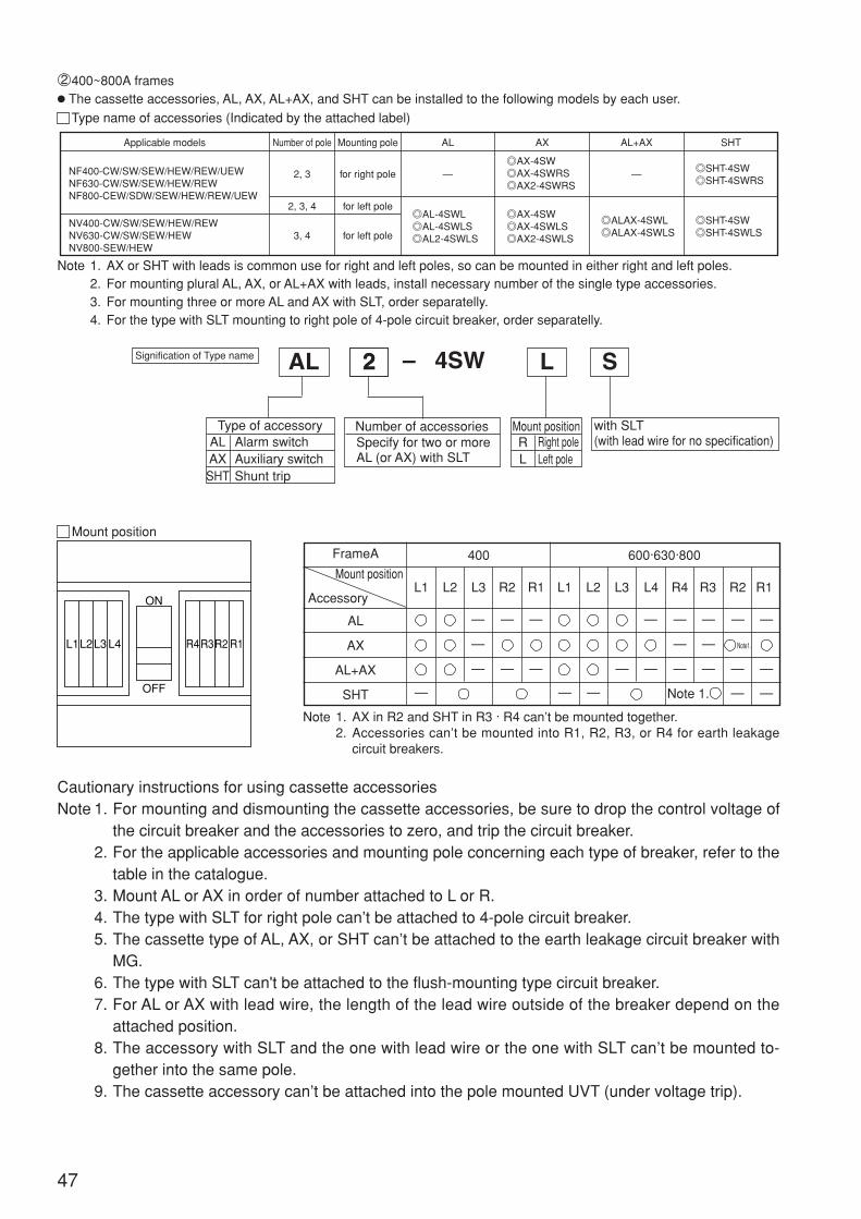
47
Cautionary instructions for using cassette accessoriesNote 1. For mounting and dismounting the cassette accessories, be sure to drop the control voltage of
the circuit breaker and the accessories to zero, and trip the circuit breaker.2. For the applicable accessories and mounting pole concerning each type of breaker, refer to the
table in the catalogue.3. Mount AL or AX in order of number attached to L or R.4. The type with SLT for right pole can’t be attached to 4-pole circuit breaker.5. The cassette type of AL, AX, or SHT can’t be attached to the earth leakage circuit breaker with
MG.6. The type with SLT can't be attached to the flush-mounting type circuit breaker.7. For AL or AX with lead wire, the length of the lead wire outside of the breaker depend on the
attached position.8. The accessory with SLT and the one with lead wire or the one with SLT can’t be mounted to-
gether into the same pole.9. The cassette accessory can’t be attached into the pole mounted UVT (under voltage trip).
2400~800A frames The cassette accessories, AL, AX, AL+AX, and SHT can be installed to the following models by each user.
Type name of accessories (Indicated by the attached label)
Note 1. AX or SHT with leads is common use for right and left poles, so can be mounted in either right and left poles.2. For mounting plural AL, AX, or AL+AX with leads, install necessary number of the single type accessories.3. For mounting three or more AL and AX with SLT, order separatelly.4. For the type with SLT mounting to right pole of 4-pole circuit breaker, order separatelly.
Signification of Type name 2AL 2 L S– 4SW
with SLT(with lead wire for no specification)
Type of accessoryALAXSHT
Alarm switchAuxiliary switchShunt trip
Number of accessoriesSpecify for two or moreAL (or AX) with SLT
RL
Mount positionRight poleLeft pole
Mount position
L4L3L2L1 R1R2R3R4
ON
OFF
—
—
FrameA
AL
AX
AL+AX
SHT
400 600·630·800
L1 L2 L3 R2 R1 L1 L2 L3 L4 R1R2R3R4
— — — Note 1.
—
—
—
—
—
—
Note1.
—
—
——
—
—
—
—
—
—
—
—
—
—
Note 1. AX in R2 and SHT in R3 · R4 can’t be mounted together.2. Accessories can’t be mounted into R1, R2, R3, or R4 for earth leakage
circuit breakers.
Mount position
Accessory
Applicable models Number of pole
2, 3
2, 3, 4
3, 4
for right pole
for left pole
—AX-4SWAX-4SWRSAX2-4SWRS
— SHT-4SWSHT-4SWRS
AL-4SWLAL-4SWLSAL2-4SWLS
AX-4SWAX-4SWLSAX2-4SWLS
ALAX-4SWLALAX-4SWLS
SHT-4SWSHT-4SWLSfor left pole
Mounting pole AL AX AL+AX SHT
NF400-CW/SW/SEW/HEW/REW/UEWNF630-CW/SW/SEW/HEW/REWNF800-CEW/SDW/SEW/HEW/REW/UEW
NV400-CW/SW/SEW/HEW/REWNV630-CW/SW/SEW/HEWNV800-SEW/HEW

48
1Before opening the cover, press the trip button, and loosen
the screw of the breaker cover.
2Then open the cover.
3If any middle cover or other accessories are attached, remove them before mounting the cassett accessory. (To the circuit
breaker having a middle cover, be sure to attach the middle cover while no cassette accessories are mounted.)
[Models having the middle cover] NF50-HRW(40, 50A)NF125-SW, NF125-HW, NF125-RW, NF125-UW
NV125-SW, NV125-HW,
NF100-HEP, NV100-HEPNF250-HEW, NF250-UW
NV250-HEW
NF800-HEW, NF800-REW, NF800-UEWNV800-HEW
How to attach cassette accessories
• For mounting and dismounting the cassette accessories, be sure to drop voltage of the circuit breaker and theaccessories to zero as electrification can result.Burning can take place should the circuit breaker operation for breaking.
• Never attach while the handle is at ON, OFF position. The parts are broken and can cause failure.
CAUTION
Trip
Don't move the coverfrom side to side.
Middle cover
➀
➁

49
4Push the accessory into the circuit breaker to the point
where click sound is heard.
• Don’t mount at ON, OFF position. Theaccessory may fail normal operation ormay be broken.
• With lead wires • With the lead wire terminal block SLT
For 600~800A frames with lead wires, fix the lead wires onthe side of the breaker by the attachment.
5Close the cover and tighten the screws. 6Close the cover and tighten the screws.Attach the name plate packed together onto a side of thecircuit breaker. (except with SLT type)
7Attach assembling the accessory, be sure to check for smooth operation before use.
Note 1. Please do not re-use what once removed cassette accessories after use. (Since the environment, the number of times
of use, and the storage situation are unknown, quality cannot be guaranteed.
2. The lead wire which is not used should perform insulated processing of the end of the lead wire.
clicksound
➀
➁
For exceeding six lead-wires
Fastening torque
Nam
e pl
ate
0.9~1.2N・m
• The state that attached accessory

(6) EAL (Earth leakage alarm switch)
This switch is for electrically indicating tripped state of an earth leakage circuit breaker at a ground
fault.
Operation of EAL switch Rating of EAL (400A frame and above)
Rating of EAL switch (250A frame and below)
Rating of micro load EAL switch (400A frame and above)
50
Condition ofcircuit breaker
Contact condition of EAL switch
Tripped by overloador short-circuit fault
ON·OFF
Tripped by groundfault
250A fram andbelow
400A fram andabove
250A fram andbelow
400A fram andabove
AC
200100
Resistance load33
Induction load22
Current AVoltageV
1 Connect the wires in the right way. Wrong connection can cause malfunction or short circuit.
2 Avoid electrification, ground fault and contact with the main circuit as EAL output is internally con-nected with the control power.
CAUTION
Before starting operation, be sure to press the test button of the earth leakage circuit breaker to make
sure of operation. The test button doesn’t operate unless voltage is applied between the right and left
pole of the breaker.
Specify voltage as the switch for100V differs from that for 200V.Control power is necessary at each voltage. For wire connection,see the drawing at right.
For use in micro current area, please enquire us separately.(Note) For model of breakers to be assembled each type of micro
switch, refer to the catalogue.
125125
Current A Current AVoltage
V
SBVB
Microswitchused
AC DC
VoltageV
0.10.1
––
Resistanceload
Inductionload
3030
0.10.1
––
Resistanceload
Inductionload
Rating of corrosion-proof EAL switch (400A frame and above)Micro switchof corrosion-
proof typeused
Resistanceload
Inductionload
AC
VoltageV
Current A Current AVoltage
V
VT
ST
DC
460250125460250125
–35155
–23
0.544
2501253025012530
0.20.44
0.30.45
0.20.43
0.30.43
Resistanceload
Inductionload
For c
orros
ion-pr
oof ty
pe
If the breaker is treated by the 1st kind moisture-fungus treatment orby added corrosion-proof treatment, the micro switch of corrosion-proof type is to be used.
Current A Current AVoltage
V
V
S
Microswitchused
AC DC
VoltageV
460250125460250125
–3551010
–2321010
Resistanceload
Inductionload
2501253025012530
0.20.44
0.30.610
0.20.43
0.30.66
Resistanceload
Inductionload78 (open)
77
98 (open)96 (closed)
78 (closed)
77
98 (closed)96 (open)95
95
L1(77)
Vertical type lead wireterminal block
78 Indicator lamp(Example)
Controlpowersource
L2
78
L2
L1(77)
78
L2
L1(77)
78
L2
L1(77)
Malfunction
MalfunctionEAL wrong connection mode
Connection whichcauses short-circuit
Malfunction
SB
(mA)
X
S, STV, VT
VBAC
DC
AC:DC
125100
60
30
10
5
0.67 1 4 26 50 100 160 600
(V)
For lower area than above limit of applicable load, use the switch forminute load.

51
(7) TBM (Test button module)
1 This module is used for testing earth leakage circuit breaker remotely while applying voltage.
For time lag type, keep applying voltage for more than two seconds.
2 The voltage application system is insulated from the main circuit and SHT of MCCB can be used
commonly with the control sequence.
Note 1. This module is manufactured for AC100-240/DC100-240V unless otherwise specified in particular.For DC24V, specify to that effect.
NV63-CW~NV250-CW, NV400-CW, NV630-CW, NV32-SW~NV250-SW, NV400-SW, NV630-SW, NV63-HW~NV250-HWNV100-SEP, NV250-SEW, NV400-SEW~NV800-SEW, NV100-HEP, NV250-HEW, NV400-HEW, NV400-REW,NV630-HEW, NV800-HEWMN50-CW, MN30-SW~MN225-SW
AC100-240/DC100-240
AC/DC80-264V 50/60Hz
(DC24V) (Note 1)
DC18-30V
1 VA max.
Circuit breaker
Lead
TBM2 Switch
TBM
TBM1
100m and below
Controlpowerside
TBM connection diagram
LineCircuit breaker
TBM
TBM2
TBM1
Port name
Cautionary instructions for useNote 1. For operation, apply voltage also to the right and the left poles of the circuit breaker. Testing of the circuit breaker fails unless
voltage is applied.2. For sequence control of TBM, keep applying voltage until operation starts.
Earth leakage circuit breaker:
3. Resetting the circuit breaker while applying voltage to the TBM and closing again trips the breaker.Reduce voltage to zero, therefore, when the circuit breaker is closed again.
4. Number of times of testing is 1,000 times. Refrain from testing over 1,000 times.5. The distance of wiring to the switch is 100m and below.
High-spped type ......... 0.1sec. or longerTime lag type ............. 2 seconds min.(
Control inputrated voltage
Applicablevoltage rangeControl input
Type name
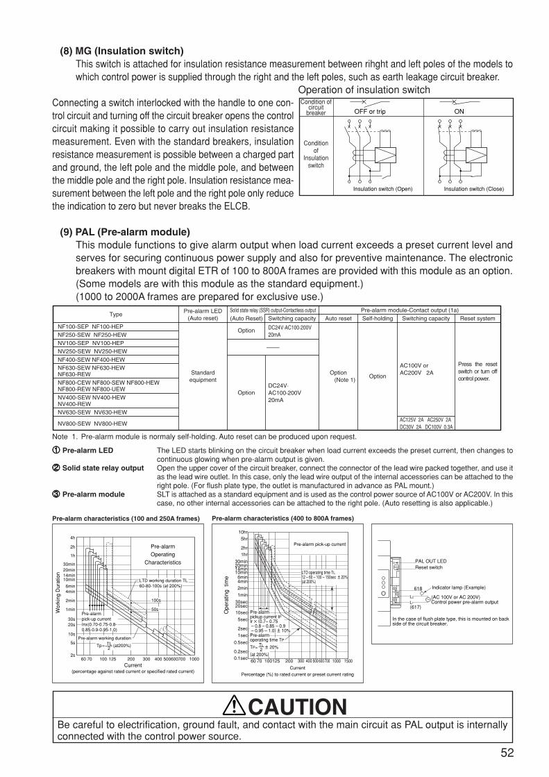
52
(8) MG (Insulation switch)This switch is attached for insulation resistance measurement between rihght and left poles of the models towhich control power is supplied through the right and the left poles, such as earth leakage circuit breaker.
Operation of insulation switchConnecting a switch interlocked with the handle to one con-trol circuit and turning off the circuit breaker opens the controlcircuit making it possible to carry out insulation resistancemeasurement. Even with the standard breakers, insulationresistance measurement is possible between a charged partand ground, the left pole and the middle pole, and betweenthe middle pole and the right pole. Insulation resistance mea-surement between the left pole and the right pole only reducethe indication to zero but never breaks the ELCB.
(9) PAL (Pre-alarm module)This module functions to give alarm output when load current exceeds a preset current level andserves for securing continuous power supply and also for preventive maintenance. The electronicbreakers with mount digital ETR of 100 to 800A frames are provided with this module as an option.(Some models are with this module as the standard equipment.)(1000 to 2000A frames are prepared for exclusive use.)
11111 Pre-alarm LED The LED starts blinking on the circuit breaker when load current exceeds the preset current, then changes tocontinuous glowing when pre-alarm output is given.
22222 Solid state relay output Open the upper cover of the circuit breaker, connect the connector of the lead wire packed together, and use itas the lead wire outlet. In this case, only the lead wire output of the internal accessories can be attached to theright pole. (For flush plate type, the outlet is manufactured in advance as PAL mount.)
33333 Pre-alarm module SLT is attached as a standard equipment and is used as the control power source of AC100V or AC200V. In thiscase, no other internal accessories can be attached to the right pole. (Auto resetting is also applicable.)
Pre-alarm characteristics (100 and 250A frames) Pre-alarm characteristics (400 to 800A frames)
Be careful to electrification, ground fault, and contact with the main circuit as PAL output is internallyconnected with the control power source.
CAUTION
Condition ofcircuit
breaker
Conditionof
Insulationswitch
OFF or trip ON
Insulation switch (Open) Insulation switch (Close)
4h
2h
1h
30min20min14min10min
6min4min
2min
1min
30s20s
10s
5s
2s60 70 100 125 200
LTD working duration TL60-80-100s (at 200%)
100s
50sPre-alarmpick-up currentInx(0.70-0.75-0.8-0.85-0.9-0.95-1.0)
300 400 500600700 1000
Pre-alarmOperating
Characteristics
Pre-alarm working duration
Tp= TL (at200%)2
Current(percentage against rated current or specified rated current)
Wor
king
Dur
atio
n
500
5hr
10hr
2hr1hr
30min
10min
20min14min
6min4min2min
1min
30sec20sec10sec
5sec
2sec
1sec
0.5sec
0.2sec
Ope
ratin
g ti
me
0.1sec
Pre-alarm pick-up current
LTD operating time TL12 – 60 – 100 – 150sec ± 20%(at 200%)
60 70 100125 200 300 400 600700 1000 1500
CurrentPercentage (%) to rated current or preset current rating
TL
2
Pre-alarmpickup current IPIr × (0.7– 0.75 – 0.8 – 0.85 – 0.9 – 0.95 – 1.0) ± 10%Pre-alarmoperating time TP
TP= ± 20%
(at 200%)
PAL OUT LEDReset switch
Indicator lamp (Example)618
(AC 100V or AC 200V)Control power pre-alarm output
L2
L1
(617)
In the case of flush plate type, this is mounted on backside of the circuit breaker.
RESET
Type Pre-alarm LED(Auto reset)
Standardequipment
Option
Option
DC24V·AC100·200V20mA
Solid state relay (SSR) output-Contactless output(Auto Reset)
—
DC24V·AC100·200V20mA
Switching capacityPre-alarm module-Contact output (1a)
Auto reset Switching capacitySelf-holding Reset system
Option
AC100V or AC200V 2AOption
(Note 1)
AC125V 2A AC250V 2ADC30V 2A DC100V 0.3A
Press the reset switch or turn off control power.
NF100-SEP NF100-HEPNF250-SEW NF250-HEWNV100-SEP NV100-HEPNV250-SEW NV250-HEW
NV630-SEW NV630-HEW
NV800-SEW NV800-HEW
NF400-SEW NF400-HEW NF630-SEW NF630-HEW NF630-REWNF800-CEW NF800-SEW NF800-HEW NF800-REW NF800-UEWNV400-SEW NV400-HEW NV400-REW
Note 1. Pre-alarm module is normaly self-holding. Auto reset can be produced upon request.
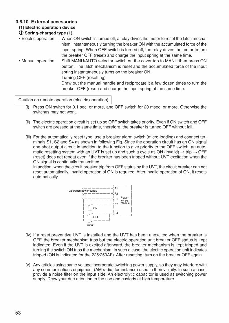
53
3.6.10 External accessories(1) Electric operation device11111 Spring-charged type (1)• Electric operation : When ON switch is turned off, a relay drives the motor to reset the latch mecha-
nism, instantaneously turning the breaker ON with the accumulated force of theinput spring. When OFF switch is turned off, the relay drives the motor to turnthe breaker OFF (reset) and charge the input spring at the same time.
• Manual operation : Shift MANU/AUTO selector switch on the cover top to MANU then press ONbutton. The latch mechanism is reset and the accumulated force of the inputspring instantaneously turns on the breaker ON.Turning OFF (resetting)Draw out the manual handle and reciprocate it a few dozen times to turn thebreaker OFF (reset) and charge the input spring at the same time.
Caution on remote operation (electric operation)
(i) Press ON switch for 0.1 sec. or more, and OFF switch for 20 msec. or more. Otherwise theswitches may not work.
(ii) The electric operation circuit is set up so OFF switch takes priority. Even if ON switch and OFFswitch are pressed at the same time, therefore, the breaker is turned OFF without fail.
(iii) For the automatically reset type, use a breaker alarm switch (micro-loading) and connect ter-minals S1, S2 and S4 as shown in following Fig. Since the operation circuit has an ON signalone-shot output circuit in addition to the function to give priority to the OFF switch, an auto-matic resetting system with an UVT is set up and such a cycle as ON (invalid) → trip → OFF(reset) does not repeat even if the breaker has been tripped without UVT excitation when theON signal is continually transmitted.In addtion, when the circuit breaker trip from OFF status by the UVT, the circuit breaker can notreset automatically. Invalid operation of ON is required. After invalid operation of ON, it resetsautomatically.
(iv) If a reset preventive UVT is installed and the UVT has been unexcited when the breaker isOFF, the breaker mechanism trips but the electric operation unit breaker OFF status is keptindicated. Even if the UVT is excited afterward, the breaker mechanism is kept tripped andturning the switch ON trips the mechanism. In such a case, the electric operation unit indicatestripped (ON is indicated for the 225·250AF). After resetting, turn on the breaker OFF again.
(v) Any articles using same voltage incorporate switching power supply, so they may interfere withany communications equipment (AM radio, for instance) used in their vicinity. In such a case,provide a noise filter on the input side. An electrolytic capacitor is used as switching powersupply. Draw your due attention to the use and custody at high temperature.
Operation power supply
Powersupplymodule
P1
P2
S1
S2ON
OFF
AL“a”
S4
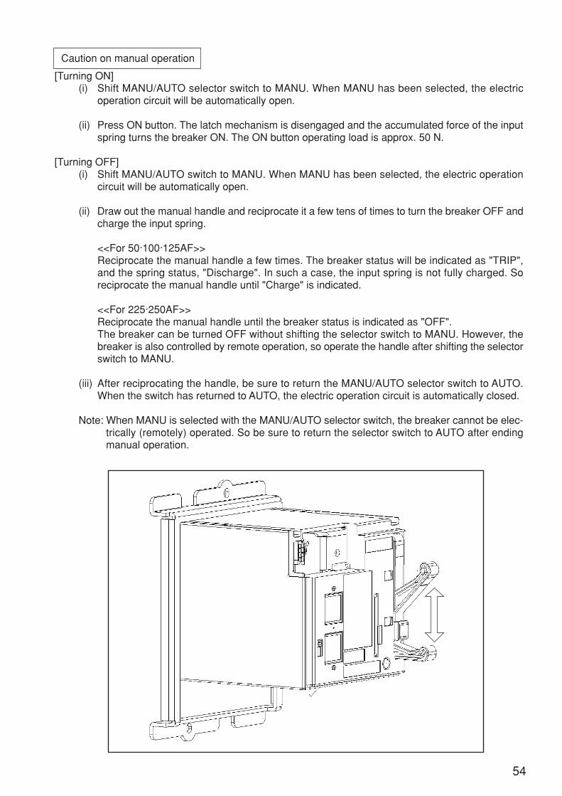
Caution on manual operation
[Turning ON](i) Shift MANU/AUTO selector switch to MANU. When MANU has been selected, the electric
operation circuit will be automatically open.
(ii) Press ON button. The latch mechanism is disengaged and the accumulated force of the inputspring turns the breaker ON. The ON button operating load is approx. 50 N.
[Turning OFF](i) Shift MANU/AUTO switch to MANU. When MANU has been selected, the electric operation
circuit will be automatically open.
(ii) Draw out the manual handle and reciprocate it a few tens of times to turn the breaker OFF andcharge the input spring.
<<For 50·100·125AF>>Reciprocate the manual handle a few times. The breaker status will be indicated as "TRIP",and the spring status, "Discharge". In such a case, the input spring is not fully charged. Soreciprocate the manual handle until "Charge" is indicated.
<<For 225·250AF>>Reciprocate the manual handle until the breaker status is indicated as "OFF".The breaker can be turned OFF without shifting the selector switch to MANU. However, thebreaker is also controlled by remote operation, so operate the handle after shifting the selectorswitch to MANU.
(iii) After reciprocating the handle, be sure to return the MANU/AUTO selector switch to AUTO.When the switch has returned to AUTO, the electric operation circuit is automatically closed.
Note: When MANU is selected with the MANU/AUTO selector switch, the breaker cannot be elec-trically (remotely) operated. So be sure to return the selector switch to AUTO after endingmanual operation.
54
Caution on OPEN (trip) button operation
(i) Shift MANU/AUTO selector switch to MANU. When MANU has been selected, the electricoperation circuit will be automatically open.
(ii) Press OPEN (trip) button and the breaker trips. The OPEN (trip) button operating load is approx.5 N.
(iii) After pressing OPEN button, be sure to return the MANU/AUTO selector switch to AUTO.When AUTO has been selected, the electric operation circuit is automatically closed.
Note 1: The breaker is structured so OPEN (trip) button cannot be pressed when the breaker isOFF.
Note 2: Be sure not to turn the breaker OFF with the OPEN (trip) button pressed. Otherwise theelectric operation unit may be damaged.
Caution on test button operation
(i) To check the test button operation, check the breaker leakage indicator button through theinspection hole at the right side of the electric operation unit. Also check that the breakeroperation status is indicated as "trip (yellow)" (for the 50·100·125AF).
Earth leakage breaker delay time and sensitivity selection
• Take the following procedure:(i) Remove the operation circuit terminal wire and a power supply module setscrew to remove the
power supply module from the electric operation base.
(ii) Remove 2 setscrews from the electric operation unit, and remove the electric operation basefrom the breaker.
(iii) Set the breaker sensitivity current selector switch and the earth leakage tripping time selectorswitch.
(iv) After setting them, install the electric operation base and the power supply module.
(v) Replace the sensitivity current nameplate and the earth leakage tripping time nameplate withthose for the newly set ones.
(vi) Connect the operation circuit terminal again.
(vii) Check each operation again.
55
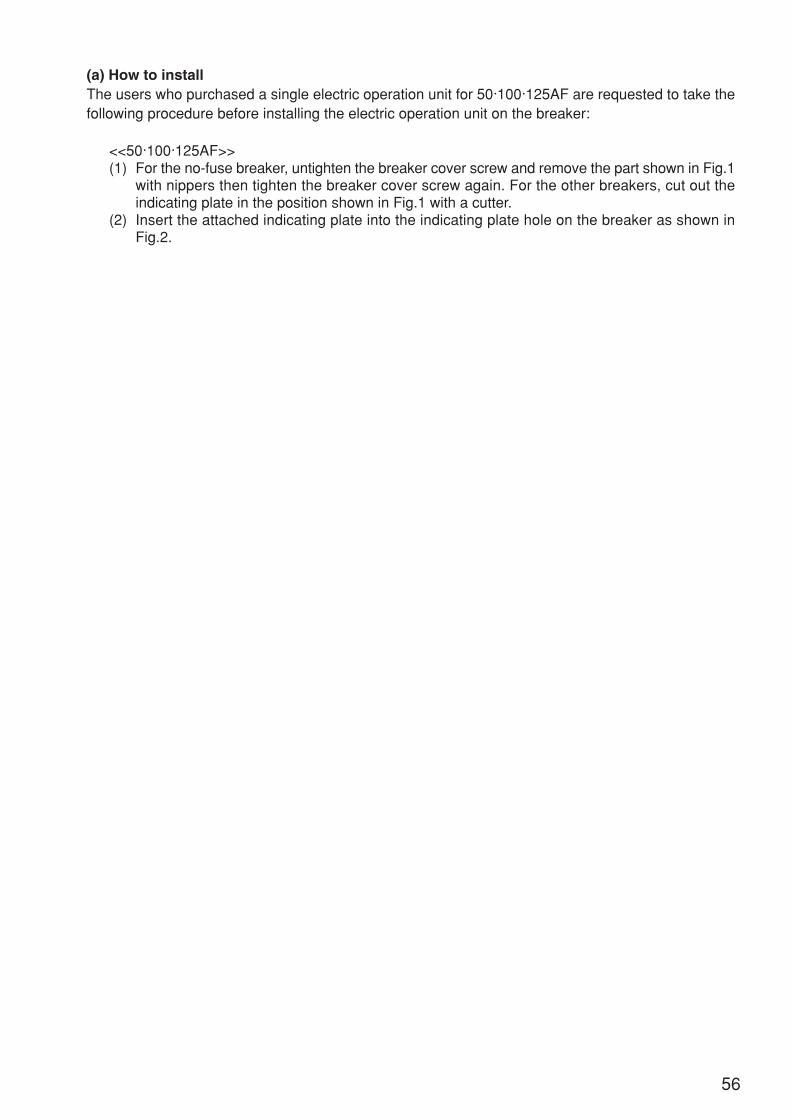
(a) How to installThe users who purchased a single electric operation unit for 50·100·125AF are requested to take thefollowing procedure before installing the electric operation unit on the breaker:
<<50·100·125AF>>(1) For the no-fuse breaker, untighten the breaker cover screw and remove the part shown in Fig.1
with nippers then tighten the breaker cover screw again. For the other breakers, cut out theindicating plate in the position shown in Fig.1 with a cutter.
(2) Insert the attached indicating plate into the indicating plate hole on the breaker as shown inFig.2.
56
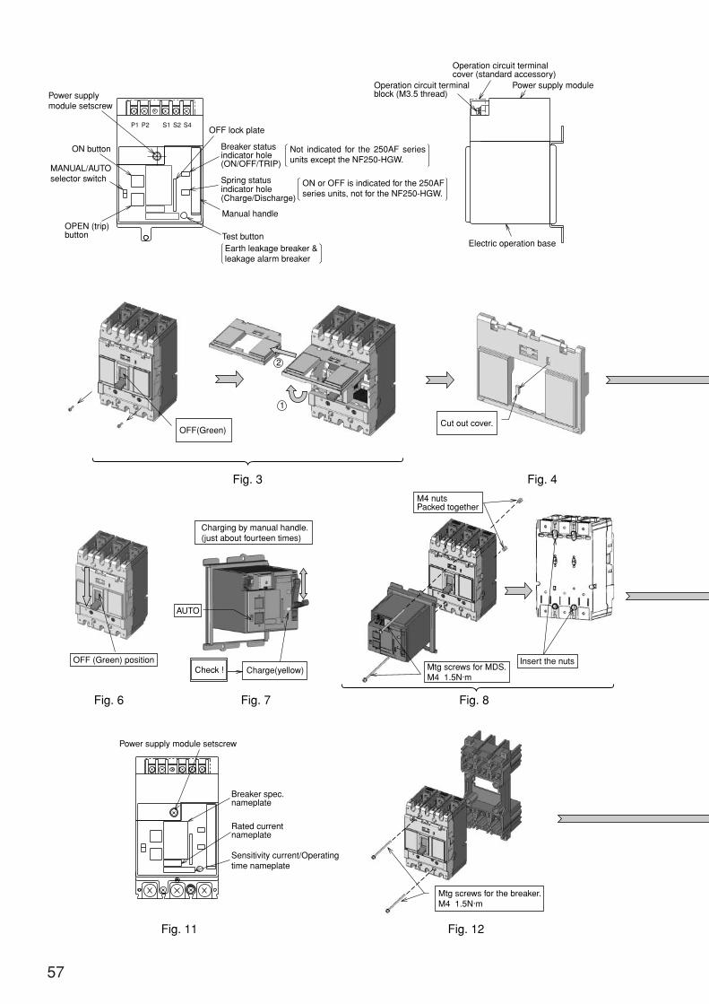
57
P1 P2 S1 S2 S4
Fig. 3 Fig. 4
OFF(Green)
Power supplymodule setscrew
OFF lock plate
Operation circuit terminalblock (M3.5 thread)
Operation circuit terminalcover (standard accessory)
Power supply module
Electric operation base
Breaker statusindicator hole(ON/OFF/TRIP)
Spring statusindicator hole(Charge/Discharge)
Test button
Manual handle
Earth leakage breaker &leakage alarm breaker
ON button
MANUAL/AUTOselector switch
OPEN (trip)button
OFF (Green) position
Power supply module setscrew
Breaker spec.nameplate
Rated currentnameplate
Sensitivity current/Operatingtime nameplate
AUTO
Charge(yellow)
Charging by manual handle.(just about fourteen times)
Cut out cover.
M4 nutsPacked together
Mtg screws for MDS.M4 1.5N·m
Mtg screws for the breaker.M4 1.5N·m
Insert the nuts
2
1
Fig. 6 Fig. 7 Fig. 8
Fig. 11 Fig. 12
Check !
ON or OFF is indicated for the 250AF series units, not for the NF250-HGW.
Not indicated for the 250AF series units except the NF250-HGW.
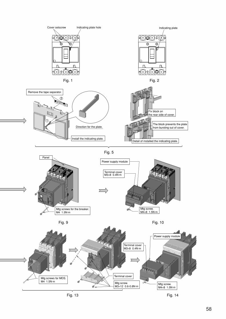
58
Fig. 2
Fig. 5
Fig. 1
Mtg screws for MDS.M4 1.5N·m
Mtg screws for the breaker.M4 1.5N·m
Mtg screw.M4×8 1.5N·m
Mtg screw.M4×8 1.5N·m
Mtg screw.M3×12 0.6-0.8N·m
Terminal coverM3×8 0.4N·m
Terminal coverM3×8 0.4N·m
Terminal cover
Panel
Remove the tape separator.
Cover setscrew Indicating plate hole Indicating plate
Install the indicating plate.Detail of installed the indicating plate.
Power supply module
Power supply module
Fix block onthe rear side of cover.
The block prevents the platefrom bursting out of cover.Direction for the plate.
2
1
Fig. 9 Fig. 10
Fig. 14Fig. 13
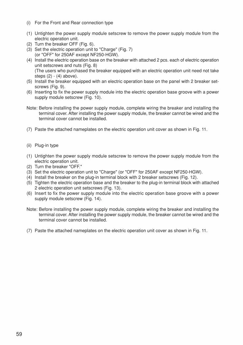
(i) For the Front and Rear connection type
(1) Untighten the power supply module setscrew to remove the power supply module from theelectric operation unit.
(2) Turn the breaker OFF (Fig. 6).(3) Set the electric operation unit to "Charge" (Fig. 7)
(or "OFF" for 250AF except NF250-HGW).(4) Install the electric operation base on the breaker with attached 2 pcs. each of electric operation
unit setscrews and nuts (Fig. 8)(The users who purchased the breaker equipped with an electric operation unit need not takesteps (2) - (4) above).
(5) Install the breaker equipped with an electric operation base on the panel with 2 breaker set-screws (Fig. 9).
(6) Inserting to fix the power supply module into the electric operation base groove with a powersupply module setscrew (Fig. 10).
Note: Before installing the power supply module, complete wiring the breaker and installing theterminal cover. After installing the power supply module, the breaker cannot be wired and theterminal cover cannot be installed.
(7) Paste the attached nameplates on the electric operation unit cover as shown in Fig. 11.
(ii) Plug-in type
(1) Untighten the power supply module setscrew to remove the power supply module from theelectric operation unit.
(2) Turn the breaker "OFF."(3) Set the electric operation unit to "Charge" (or "OFF" for 250AF except NF250-HGW).(4) Install the breaker on the plug-in terminal block with 2 breaker setscrews (Fig. 12).(5) Tighten the electric operation base and the breaker to the plug-in terminal block with attached
2 electric operation unit setscrews (Fig. 13).(6) Insert to fix the power supply module into the electric operation base groove with a power
supply module setscrew (Fig. 14).
Note: Before installing the power supply module, complete wiring the breaker and installing theterminal cover. After installing the power supply module, the breaker cannot be wired and theterminal cover cannot be installed.
(7) Paste the attached nameplates on the electric operation unit cover as shown in Fig. 11.
59

(b) Operation circuit connection
(i) Connect the operation power supply to the operation power supply terminals (P1 and P2).There is no polarity.
(ii) Connect ON switch and OFF switch to the operation switch terminals (S1, S2 and S4). For theoperation switches, use the micro-loading switches (with approx. DC 24 V, 30 mA of switchingcapacities) prepared at your side.
Note: For the voltage sharing items, the rush current (capacitor charging current 60A 1msec) men-tioned later flows to the breaker and the fuse in the power supply circuit. So select the itemswith care to prevent fusion and operation errors.
60
(c) Caution on withstand voltage tests
The withstand voltage between the operation circuit terminals (P1, P2, S1, S2 and S4) and theground is AC 1500 V.
P.S
SW1
SW2
M
K1
K2
K3
X
Switching power supply (AC 100-240 V/DC 100-250 V types only)
MANU/AUTO selector switch
Charge/Discharge detecting switch
Motor
Relay (for OFF switch)
Relay (for the motor)
Relay (for the motor)
Pumping preventive circuit
Operatingpower supply
Power supply module
The breaker indicates OFF and the electric operationunit is Charged.
Electric operation base
SW2
SW1 K3K3
K2
K2
K1K1
K3
K2
K1
MUc
S4
S2
S1
P2X
P1 P.SPowerSupply
OFF(RESET)
ON

33333 Motor-operated type (2)• Electrical Operation : The circuit-breaker is turned ON/OFF (reset) converting the forward and re-
verse rotation of motor into rectilinear motion by ball screw.• Manual Operation : Manual operation handle is
manipulated directly towardOn or Off side of the circuit-breaker.
(a) Precaution to be taken for handling
Every time the electrical operation unit is dismantled or remounted, turn off the master circuit-breaker, switch off the operational circuit to make sure that the main and operational circuitsare not alive (charged). Beware of electric shock. Notice that the manual operation handleoperates at high speed during electric operation. Never try to perform the electric operationwith cover opened. Turn off the power supply for operational circuit at the time of manualoperation.
CAUTION
(i) When the circuit-breaker trips, the resetting (reclosing) procedure depends on the status of theelectric operation unit before the trip:Trip with unit ON: Resettting (OFF) operation → ON operationTrip with unit OFF: ON operation → Resetting (OFF) operation → ON operation.
(ii) Never try to apply ON and OFF operation signals continuously. There must be a time interval of0.5 sec or longer between the ON and OFF signals.
(iii) Since the electric operation unit is of intermittent rating, never try to operate 10 times or morecontinuously (ON and OFF consecutive operation is counted as one operation).
(iv) The operational voltage shall be within 85 to 110% of the rated operation voltage.(v) In case of automatic reset mode, resetting operation shall be made with 0.5 sec of time interval
after the NFB tripped.(vi) Note that the electrical operation unit will not display the trip when the circuit-breaker trips due
to some trouble (overload, short-circuit, leakage), internal accessories (UVT, SHT) or to the tripbutton, test button.
(vii) The electrical operation unit incorporating pumping prevention device, it can be turned offwhile the ON switch is maintained thrown, but it cannot be turned ON continuously after that. Ifit is to be turned on, once change the ON switch over to OFF, and then apply again the ONswitch.
(viii)In the manual operation mode, make sure to manipulate the manual operation handle up to theposition indicated by the name plate.
(ix) The withstand voltage of the electrical operation circuit is 1500V. If the withstand voltage test isperformed under a voltage exceeding 1500V together with other equipment, cut off the termi-nals (P1, P2, S2 and S4) of the operational circuit.
(x) Note that the leak sensitivity current and action time changeover device for Earth leakagecircuit breakers have been set 500 mA 2.0 sec (at delivery). If the user wants to change thissetting, proceed to the change only after removing the frame.
Make sure to operate up tothe position indicated bythe name plate. (Shouldthe operation be sus-pended midway, the limitswitch for electrical opera-tion may possibly not func-tion, which will cause anerror. In case when the unit is provided with the internal acces-
sory for NFB, the terminal block of its lead-wire is mountedon the NFB.
Structure (with the cover for motor-operated typeelectrical operation unit removed)
Fig. 2 Manual Operation
ONON
OFF(RESET)
61

(b) Mounting(i) Front-connection/Rear-connection (Other than the U-series).(i)-1 Sequential order for mounting the electrical operation type MCCB
a) Detach the four cover mount screws (A) to remove the cover.b) Fix the electric operation type MCCB on the panel using four MCCB
mount screws (B).c) Connect the electric operation unit to the terminal of operational circuit.d) Fasten the cover with four cover mount screws (A).
(i)-2 Maintenance and inspection of electrical operation unit (Removalof this unit only)
a) Detach the four cover mount screws (A) to remove the cover.b) Remove the four frame mount screws (C).c) Slide the electric operation unit slightly toward the power supply
side to remove the frame from hook pin. When mounting the unit on the MCCB, thread the handle between
the rollers of the bracket beforehand. The electric operation unithas been so designed that it may be supported temporarily by thehook pin in case of setting with screws.
Mount the electric operation unit so that the end of the trip levermatches with the position of the trip button of MCCB.
The end of the trip lever projects from the plane F of the frame.Take care not to allow the trip lever to be deformed.
(ii) Flush plate type (Other than the U-series)a) Mounting the electric operation type MCCB
Fix the MCCB on the panel or the like using the attaching (mount)screws (E) for flash plate.
NF1600-SEW/SDW shall be mounted with the mount angle ofMCCB.
b) Maintenance and inspection of electrical operation unit (Removalof this unit only) Same as for front connection/rear connection types.Note. When mounting 800 AF and subsequents, the smaller slider
out of the two sorts of sliders (insulating plates) betweenthe bracket and cover shall be incorporated into the upperplane, and the notched portion of the larger one into thelower left corner.
(iii) Mounting the front-connection and rear-connection (U-series)(iii)-1 NF400-SEW (3P)
a) Detach the electrical operation unit from the circuit-breaker.Step 1 Detach the four cover mount screws (A) to remove the
cover.Step 2 Remove the four frame mount screws (C).Step 3 Slide the electric operation unit slightly toward the power
supply side to remove the frame from hook pin to removethe electric operation unit from the circuit-breaker.
Precaution to be taken:The end of the trip lever projects from the plane F of the frame.Take care not to allow the trip lever to be deformed.
b) Mount the circuit-breaker on the board using four circuit-breakermount screws (B). The mounting onto the board is the same asthat of the circuit-breaker both for front connection and rear con-nection types.
c) Mount the electric operation unit in the sequential order reverse to a).Note 1. When mounting on the circuit-breaker, thread the handle
between the rollers of the bracket beforehand.Note 2. The electric operation unit has been so designed that it
may be supported temporarily by the hook pin in case ofsetting with screws.
Note 3. Before mounting the cover, connect electric operation unitto the terminal of the operational circuit.
(A)
(C)
(B)
(D)
Cover
PlaneF
Frame
Triplever
MCCB
Tripbutton
Mount panel
Fig. 3
(A)
(C) (D)
(E)
PlaneF
Spacer
Cover
Frame
Flashplate
MCCB
Fig. 4
Fig. 3
(A)
(C)
(D)
(B)
Cover
PlaneF
Frame
Triplever
NFBHandle
Tripbutton
62
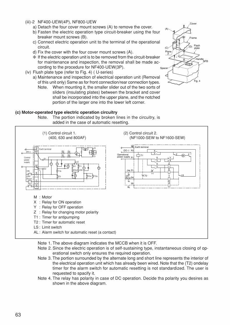
(iii)-2 NF400-UEW(4P), NF800-UEWa) Detach the four cover mount screws (A) to remove the cover.b) Fasten the electric operation type circuit-breaker using the four
breaker mount screws (B).c) Connect electric operation unit to the terminal of the operational
circuit.d) Fix the cover with the four cover mount screws (A). If the electric operation unit is to be removed from the circuit-breaker
for maintenance and inspection, the removal shall be made ac-cording to the procedure for NF400-UEW(3P).
(iv) Flush plate type (refer to Fig. 4) ( U-series)a) Maintenance and inspection of electrical operation unit (Removal
of this unit only) Same as for front connection/rear connection types.Note. When mounting it, the smaller slider out of the two sorts of
sliders (insulating plates) between the bracket and covershall be incorporated into the upper plane, and the notchedportion of the larger one into the lower left corner.
(c) Motor-operated type electric operation circuitryNote. The portion indicated by broken lines in the circuitry, is
added in the case of automatic resetting.
Note 1. The above diagram indicates the MCCB when it is OFF.Note 2. Since the electric operation is of self-sustaining type, instantaneous closing of op-
erational switch only ensures the required operation.Note 3. The portion surrounded by the alternate long and short line represents the interior of
the electrical operation unit which has already been wired. Note that the (T2) ondelaytimer for the alarm switch for automatic resetting is not standardized. The user isrequested to spacify it.
Note 4. The relay has polarity in case of DC operation. Decide tha polarity you desires asshown in the above diagram.
(1) Control circuit 1.(400, 630 and 800AF)
(2) Control circuit 2.(NF1000-SEW to NF1600-SEW)
M : MotorX : Relay for ON operationY : Relay for OFF operationZ : Relay for changing motor polarityT1 : Timer for antipumpingT2 : Timer for automatic resetLS : Limit switchAL : Alarm switch for automatic reset (a contact)
(A)
(C)
PlaneF
Spacer
Cover
Frame
(D) Flashplate
NFBHandle
Fig. 4
P2
P1
S1
S4
95
AL
YXY
Z
Z Z
X
Y
T2
T2
T1
T1LS
X
YX
YX
OFF
ON
Reset
(DC–)
MOperational power supply
Earth terminal
T2
T1
YX
M
Z
R
Z4a
Y2a T2a
X1
Z4b
Y1
T1b
Z3
E2
E1
Earth terminal
Controlpowersupply
(DC-)
ON
OFFReset
ALa
G
A1
A2
B
C
D
R3 R4
R1 R2
LS
Z2
Z1
63

44444 Spring-charged type (2)• Electrical Operation : When the ON operation switch is closed, the closing coil is excited, latch mechanism
is released and the closing spring will turn on the circuit-breaker instantaneously. Ifthe OFF operation switch is closed, the relay will come into function to start the motor.If, under these conditions, the circuit-breaker is turned OFF (reset), the closing springwill be charged instantaneously.
• Manual Operation: Depressing the ON button will release the latch mechanism, and the closingspring will turn on the circuit-breaker instantaneously.OFF (reset) Operation.When the manual lever is taken out depressing the leaf spring, and the lever isthrown a dozen times reciprocatedly, the circuit-breaker turns OFF (resetting)and the closing spring is charged at the same time.
(a) Precaution to be taken when handling
Case of remote operation (electric operation)
(i) The operational voltage shall be within the range from 85 to 110% of the rated operationalvoltage.
(ii) Since the electric operation unit is of intermittent rating, avoid operating it 10 times or morecontinuously (ON and OFF consecutive operation is counted as one operation).
(iii) The turning off by the electric operation requires about 2 sec (from application of OFF signal onthe electric operation unit to turning off of the circuit-breaker). If one wants to open urgently themain circuit by remote operation, it is recommended to use the circuit-breaker with SHT or UVT.
(iv) When the circuit-breaker trips, the resetting (reclosing) procedure depends on the status of theelectric operation unit before the trips:Trip with unit ON : Resetting (OFF) operation → ON operationTrip with unit OFF : On operation → Resetting (OFF) operation → ON operation
Case of local (manual) operation
(i) Turning ONPressing the ON button will release the latch mechanismand turn on the circuit-breaker instantaneously by the en-ergy of the closing spring.
(ii) Turning OFF (reset)The manual turning OFF (resetting) should be repeated morethan 10 times after taking out the manual lever. Repeat theoperation of manual lever without fail up until the manuallever idles. After completion of the manual operation, housethe lever into its original position.Note. Sometimes the operational load reduces more or
less midway with the circuit-breaker turning off emit-ting a sound. Never fail to continue to operate themanual lever until it does idling.
(iii) Trip operationThe circuit-breaker with the electric operation unit has beenso designed that it should not trip even if the trip button isdepressed under OFF condition. When the circuit-breaker is to be tripped on occasion, forinstance, of witnessed test, it shall either be made to trip after once it shall be turned ON orshall trip by turning it on with trip button depressed.
Every time the electrical operation unit is dismantled or remounted, turn off the mas-ter circuit-breaker, switch off the operational circuit to make sure that the main andoperational circuits are not live (charged). Beware of electric shock.
CAUTION
64
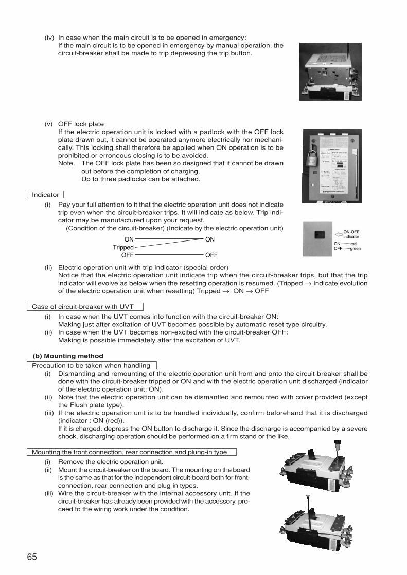
(iv) In case when the main circuit is to be opened in emergency:If the main circuit is to be opened in emergency by manual operation, thecircuit-breaker shall be made to trip depressing the trip button.
(v) OFF lock plateIf the electric operation unit is locked with a padlock with the OFF lockplate drawn out, it cannot be operated anymore electrically nor mechani-cally. This locking shall therefore be applied when ON operation is to beprohibited or erroneous closing is to be avoided.Note. The OFF lock plate has been so designed that it cannot be drawn
out before the completion of charging.Up to three padlocks can be attached.
Indicator
(i) Pay your full attention to it that the electric operation unit does not indicatetrip even when the circuit-breaker trips. It will indicate as below. Trip indi-cator may be manufactured upon your request.
(Condition of the circuit-breaker) (Indicate by the electric operation unit)
(ii) Electric operation unit with trip indicator (special order)Notice that the electric operation unit indicate trip when the circuit-breaker trips, but that the tripindicator will evolve as below when the resetting operation is resumed. (Tripped → Indicate evolutionof the electric operation unit when resetting) Tripped → ON → OFF
Case of circuit-breaker with UVT
(i) In case when the UVT comes into function with the circuit-breaker ON:Making just after excitation of UVT becomes possible by automatic reset type circuitry.
(ii) In case when the UVT becomes non-excited with the circuit-breaker OFF:Making is possible immediately after the excitation of UVT.
(b) Mounting method
Precaution to be taken when handling(i) Dismantling and remounting of the electric operation unit from and onto the circuit-breaker shall be
done with the circuit-breaker tripped or ON and with the electric operation unit discharged (indicatorof the electric operation unit: ON).
(ii) Note that the electric operation unit can be dismantled and remounted with cover provided (exceptthe Flush plate type).
(iii) If the electric operation unit is to be handled individually, confirm beforehand that it is discharged(indicator : ON (red)).If it is charged, depress the ON button to discharge it. Since the discharge is accompanied by a severeshock, discharging operation should be performed on a firm stand or the like.
Mounting the front connection, rear connection and plung-in type
(i) Remove the electric operation unit.(ii) Mount the circuit-breaker on the board. The mounting on the board
is the same as that for the independent circuit-board both for front-connection, rear-connection and plug-in types.
(iii) Wire the circuit-breaker with the internal accessory unit. If thecircuit-breaker has already been provided with the accessory, pro-ceed to the wiring work under the condition.
ONTripped
OFF
ON
OFF
65
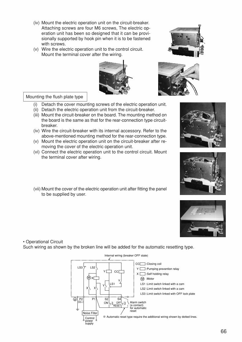
(iv) Mount the electric operation unit on the circuit-breaker.Attaching screws are four M6 screws, The electric op-eration unit has been so designed that it can be provi-sionally supported by hook pin when it is to be fastenedwith screws.
(v) Wire the electric operation unit to the control circuit.Mount the terminal cover after the wiring.
Mounting the flush plate type
(i) Detach the cover mounting screws of the electric operation unit.(ii) Detach the electric operation unit from the circuit-breaker.(iii) Mount the circuit-breaker on the board. The mounting method on
the board is the same as that for the rear-connection type circuit-breaker.
(iv) Wire the circuit-breaker with its internal accessory. Refer to theabove-mentioned mounting method for the rear-connection type.
(v) Mount the electric operation unit on the circuit-breaker after re-moving the cover of the electric operation unit.
(vi) Connect the electric operation unit to the control circuit. Mountthe terminal cover after wiring.
(vii) Mount the cover of the electric operation unit after fitting the panelto be supplied by user.
• Operational CircuitSuch wiring as shown by the broken line will be added for the automatic resetting type.
P2 P1
Noise Filter
S2 S4
CCY
Y
YX
X
X
LS1 LS1
Internal wiring (breaker OFF state)
LS2
LS3
LS3 LS2
OFFRESET
ON
M M
Y
X
CC :Closing coil
:Pumping prevention relay
:Self holding relay
:Motor
:Limit switch linked with a cam
Alarm switch(a contact)for automaticreset
※ Automatic reset type require the additional wiring shown by dotted lines.
:Limit switch linked with a cam
:Limit switch linked with OFF lock plate
(DC–)
Controlpowersupply
66
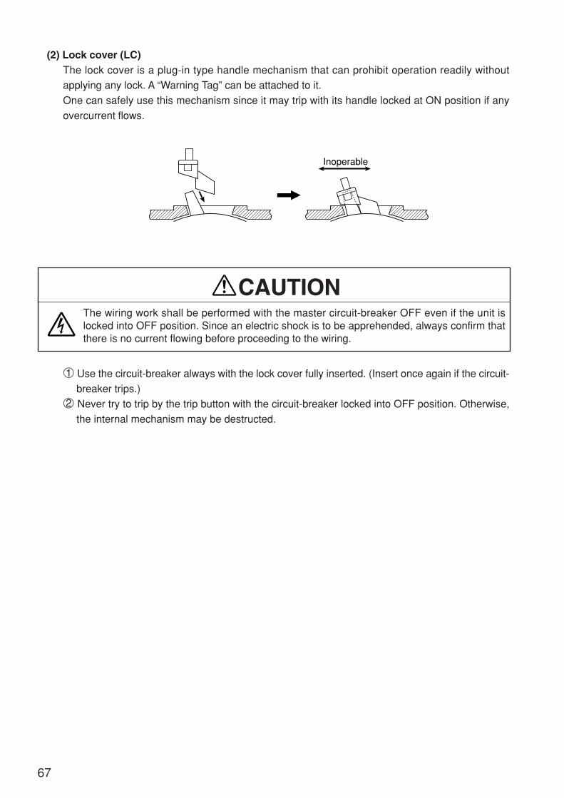
(2) Lock cover (LC)The lock cover is a plug-in type handle mechanism that can prohibit operation readily without
applying any lock. A “Warning Tag” can be attached to it.
One can safely use this mechanism since it may trip with its handle locked at ON position if any
overcurrent flows.
1 Use the circuit-breaker always with the lock cover fully inserted. (Insert once again if the circuit-
breaker trips.)
2 Never try to trip by the trip button with the circuit-breaker locked into OFF position. Otherwise,
the internal mechanism may be destructed.
The wiring work shall be performed with the master circuit-breaker OFF even if the unit islocked into OFF position. Since an electric shock is to be apprehended, always confirm thatthere is no current flowing before proceeding to the wiring.
CAUTION
Inoperable
67
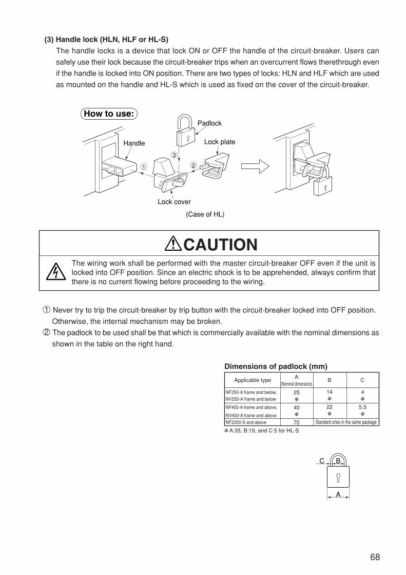
(3) Handle lock (HLN, HLF or HL-S)
The handle locks is a device that lock ON or OFF the handle of the circuit-breaker. Users can
safely use their lock because the circuit-breaker trips when an overcurrent flows therethrough even
if the handle is locked into ON position. There are two types of locks: HLN and HLF which are used
as mounted on the handle and HL-S which is used as fixed on the cover of the circuit-breaker.
1 Never try to trip the circuit-breaker by trip button with the circuit-breaker locked into OFF position.
Otherwise, the internal mechanism may be broken.
2 The padlock to be used shall be that which is commercially available with the nominal dimensions as
shown in the table on the right hand.
Dimensions of padlock (mm)
The wiring work shall be performed with the master circuit-breaker OFF even if the unit islocked into OFF position. Since an electric shock is to be apprehended, always confirm thatthere is no current flowing before proceeding to the wiring.
CAUTION
Applicable type
NF250-A frame and below,NV250-A frame and below
NF400-A frame and above,
NV400-A frame and aboveNF2000-S and above
A(Nominal dimensions)
B C
25
40
70
14
22
4
5.5
Standard ones in the same package
A:35, B:19, and C:5 for HL-S
How to use:
Handle
Lock cover
(Case of HL)
Lock plate
Padlock
1
3
2
A
BC
68
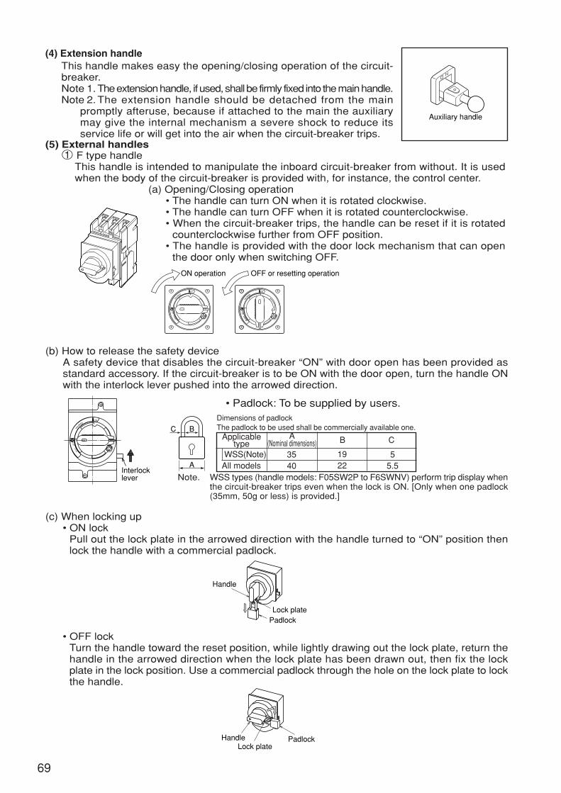
(4) Extension handleThis handle makes easy the opening/closing operation of the circuit-breaker.Note 1. The extension handle, if used, shall be firmly fixed into the main handle.Note 2. The extension handle should be detached from the main
promptly afteruse, because if attached to the main the auxiliarymay give the internal mechanism a severe shock to reduce itsservice life or will get into the air when the circuit-breaker trips.
(5) External handles1 F type handle
This handle is intended to manipulate the inboard circuit-breaker from without. It is usedwhen the body of the circuit-breaker is provided with, for instance, the control center.
(a) Opening/Closing operation• The handle can turn ON when it is rotated clockwise.• The handle can turn OFF when it is rotated counterclockwise.• When the circuit-breaker trips, the handle can be reset if it is rotated
counterclockwise further from OFF position.• The handle is provided with the door lock mechanism that can open
the door only when switching OFF.
(b) How to release the safety deviceA safety device that disables the circuit-breaker “ON” with door open has been provided asstandard accessory. If the circuit-breaker is to be ON with the door open, turn the handle ONwith the interlock lever pushed into the arrowed direction.
• Padlock: To be supplied by users.Dimensions of padlockThe padlock to be used shall be commercially available one.
WSS(Note)All models
Applicabletype
A(Nominal dimensions) B C
3540
1922
55.5
Note. WSS types (handle models: F05SW2P to F6SWNV) perform trip display whenthe circuit-breaker trips even when the lock is ON. [Only when one padlock(35mm, 50g or less) is provided.]
Auxiliary handle
ON operation OFF or resetting operation
DEPPIRT
FF
OT
REES
ON
RELE
ASE
NDEPPIRT
FF
OT
REE
S
O
RELE
ASE
C
A
B
Interlocklever
NDEPPIRT
FF
OT
REE
S
O
RELE
ASE
(c) When locking up• ON lock
Pull out the lock plate in the arrowed direction with the handle turned to “ON” position thenlock the handle with a commercial padlock.
• OFF lockTurn the handle toward the reset position, while lightly drawing out the lock plate, return thehandle in the arrowed direction when the lock plate has been drawn out, then fix the lockplate in the lock position. Use a commercial padlock through the hole on the lock plate to lockthe handle.
Handle
PadlockLock plate
Handle PadlockLock plate
69
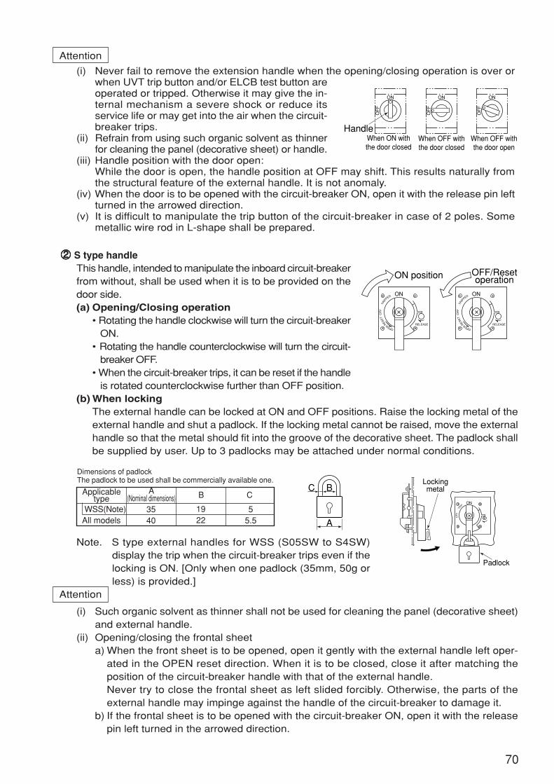
22222 S type handleThis handle, intended to manipulate the inboard circuit-breakerfrom without, shall be used when it is to be provided on thedoor side.(a) Opening/Closing operation
• Rotating the handle clockwise will turn the circuit-breakerON.
• Rotating the handle counterclockwise will turn the circuit-breaker OFF.
• When the circuit-breaker trips, it can be reset if the handleis rotated counterclockwise further than OFF position.
(b) When lockingThe external handle can be locked at ON and OFF positions. Raise the locking metal of theexternal handle and shut a padlock. If the locking metal cannot be raised, move the externalhandle so that the metal should fit into the groove of the decorative sheet. The padlock shallbe supplied by user. Up to 3 padlocks may be attached under normal conditions.
Note. S type external handles for WSS (S05SW to S4SW)display the trip when the circuit-breaker trips even if thelocking is ON. [Only when one padlock (35mm, 50g orless) is provided.]
Attention
(i) Such organic solvent as thinner shall not be used for cleaning the panel (decorative sheet)and external handle.
(ii) Opening/closing the frontal sheeta) When the front sheet is to be opened, open it gently with the external handle left oper-
ated in the OPEN reset direction. When it is to be closed, close it after matching theposition of the circuit-breaker handle with that of the external handle.Never try to close the frontal sheet as left slided forcibly. Otherwise, the parts of theexternal handle may impinge against the handle of the circuit-breaker to damage it.
b) If the frontal sheet is to be opened with the circuit-breaker ON, open it with the releasepin left turned in the arrowed direction.
Dimensions of padlockThe padlock to be used shall be commercially available one.
WSS(Note)All models
Applicabletype
A(Nominal dimensions) B C
3540
1922
55.5
RELEASE
OPEN
RESE
TO
FF
TRIP
PED ON
RELEASE
OPEN
RESE
TO
FF
TRIP
PED ON
OFF/ResetoperationON position
A
BC
OF
FTR
IPON
Lockingmetal
Padlock
Attention
(i) Never fail to remove the extension handle when the opening/closing operation is over orwhen UVT trip button and/or ELCB test button areoperated or tripped. Otherwise it may give the in-ternal mechanism a severe shock or reduce itsservice life or may get into the air when the circuit-breaker trips.
(ii) Refrain from using such organic solvent as thinnerfor cleaning the panel (decorative sheet) or handle.
(iii) Handle position with the door open:While the door is open, the handle position at OFF may shift. This results naturally fromthe structural feature of the external handle. It is not anomaly.
(iv) When the door is to be opened with the circuit-breaker ON, open it with the release pin leftturned in the arrowed direction.
(v) It is difficult to manipulate the trip button of the circuit-breaker in case of 2 poles. Somemetallic wire rod in L-shape shall be prepared.
HandleWhen ON withthe door closed
When OFF withthe door closed
When OFF withthe door open
ON
OF
F
ON
OF
F
ON
OF
F
70
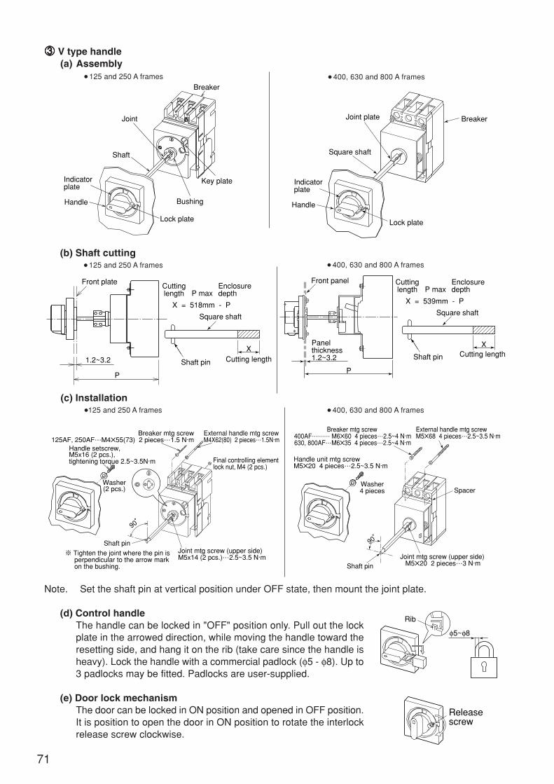
Breaker mtg screw400AF……… M660 4 pieces…2.5~4 N·m630, 800AF…M635 4 pieces…2.5~4 N·m
Handle unit mtg screwM520 4 pieces…2.5~3.5 N·m
90°
Shaft pinJoint mtg screw (upper side)
M520 2 pieces…3 N·m
External handle mtg screwM568 4 pieces…2.5~3.5 N·m
SpacerWasher4 pieces
Front panel
Panelthickness1.2~3.2
Cuttinglength P max
X = 539mm - P
Enclosuredepth
Square shaft
Shaft pin Cutting lengthX
P
Joint plate
Square shaft
Breaker
Indicatorplate
Handle
Lock plate
Front plate
1.2~3.2
Cuttinglength P max
X = 518mm - P
Enclosuredepth
Square shaft
P
Shaft pin Cutting lengthX
33333 V type handle(a) Assembly
125 and 250 A frames
(b) Shaft cutting 125 and 250 A frames
(c) Installation125 and 250 A frames
Note. Set the shaft pin at vertical position under OFF state, then mount the joint plate.
(d) Control handleThe handle can be locked in "OFF" position only. Pull out the lockplate in the arrowed direction, while moving the handle toward theresetting side, and hang it on the rib (take care since the handle isheavy). Lock the handle with a commercial padlock (φ5 - φ8). Up to3 padlocks may be fitted. Padlocks are user-supplied.
(e) Door lock mechanismThe door can be locked in ON position and opened in OFF position.It is position to open the door in ON position to rotate the interlockrelease screw clockwise.
Joint
Shaft
Indicatorplate
Handle
Lock plate
Bushing
Key plate
Breaker
400, 630 and 800 A frames
400, 630 and 800 A frames
Breaker mtg screw125AF, 250AF…M455(73) 2 pieces…1.5 N·m
Handle setscrew,M5x16 (2 pcs.),tightening torque 2.5~3.5N·m
External handle mtg screwM4X62(80) 2 pieces…1.5N·m
Washer(2 pcs.)
90°
Final controlling elementlock nut, M4 (2 pcs.)
Shaft pin
※ Tighten the joint where the pin is perpendicular to the arrow mark on the bushing.
Joint mtg screw (upper side)M5x14 (2 pcs.)…2.5~3.5 N·m
400, 630 and 800 A frames
φ5~φ8
Rib
Releasescrew
71

(f) CautionMount the external handle under OFF state.Be careful that the shaft pin rotate when the breaker is tripped under opening the door.The door cannot be closed in trip position.Reset operation under opening the door, rotate the square shaft unticlockwise by spanner or mon-key wrench.
44444 R Type handle(a) Installation
125 and 250 A frames
(b) Lock MechanismThe handle can be locked in "OFF" position only. Pull outthe lock plate in the arrowed direction, while moving thehandle toward the resetting side, and hang it on the rib(take care since the handle is heavy). Lock the handlewith a commercial padlock (φ5 - φ8).
(6) Terminal cover (400 A frame and below)11111 MOUNTING
Put the U-form projection in the hole of the breaker andpush the terminal cover strongly to fasten it.(Push the indicated place by the “ ” mark.)
22222 REMOVINGPush the tip of the U-form projection fully toward the “ ”mark by the screw driver or a finger tip and pull out theterminal cover toward the “ ” mark.
33333 SEALINGTerminal cover can be sealed with the sealing plate andwires.Put the sealing plate into the hole of the U-form projec-tion and seal the terminal cover.
Note. Pull the sealing wire so as not to loose.
Caution. Mount the external handle underOFF state.
Final controlling elementlock nut, M4 (2 pcs.)
External handle mtg screwM462(80) 2 pieces…1.5 N·m
Breaker mtg screw125AF, 250AF…M455(73) 2 pieces…1.5N·m
400AF………M660 4 pieces…2.5~4 N · m630, 800AF…M635 4 pieces…2.5~4 N · m
Breaker mtg screw
Status indicator plate
Breaker
Spacer
Lock plate
Breaker spec
Rated current
External handle mtg screwM568 4 pieces…2.5~3.5 N · m
400, 630 and 800 A frames
U-formprojection
the tip of theU-form projection
sealing plate
seal
φ5~φ8
Rib
72
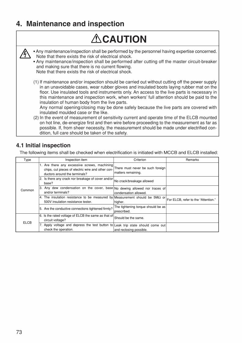
4. Maintenance and inspection
4.1 Initial inspectionThe following items shall be checked when electrification is initiated with MCCB and ELCB installed:
Any maintenance/inspection shall be performed by the personnel having expertise concerned.Note that there exists the risk of electrical shock.
Any maintenance/inspection shall be performed after cutting off the master circuit-breakerand making sure that there is no current flowing.Note that there exists the risk of electrical shock.
(1) If maintenance and/or inspection should be carried out without cutting off the power supplyin an unavoidable cases, wear rubber gloves and insulated boots laying rubber mat on thefloor. Use insulated tools and instruments only. An access to the live parts is necessary inthis maintenance and inspection work, when workers’ full attention should be paid to theinsulation of human body from the live parts.Any normal opening/closing may be done safely because the live parts are covered withinsulated moulded case or the like.
(2) In the event of measurement of sensitivity current and operate time of the ELCB mountedon hot line, de-energize first and then wire before proceeding to the measurement as far aspossible. If, from sheer necessity, the measurement should be made under electrified con-dition, full care should be taken of the safety.
CAUTION
Type Inspection item Criterion
There must never be such foreign matters remaining.
No dewing allowed nor traces of condensation allowed.Measurement should be 5MΩ or higher.
The tightening torque should be as prescribed.
For ELCB, refer to the “Attention.”
Leak trip state should come out and reclosing possible.
No crack/breakage allowed
Should be the same.
Remarks
1. Are there any excessive screws, machining chips, cut pieces of electric wire and other con-ductors around the terminals?
2. Is there any crack nor breakage of cover and/or base?
3. Any dew condensation on the cover, base and/or terminals?
4. The insulation resistance to be measured by 500V insulation resistance tester.
5. Are the conductive connections tightened firmly?
6. Is the rated voltage of ELCB the same as that of circuit voltage?
7. Apply voltage and depress the test button to check the operation.
Common
ELCB
73
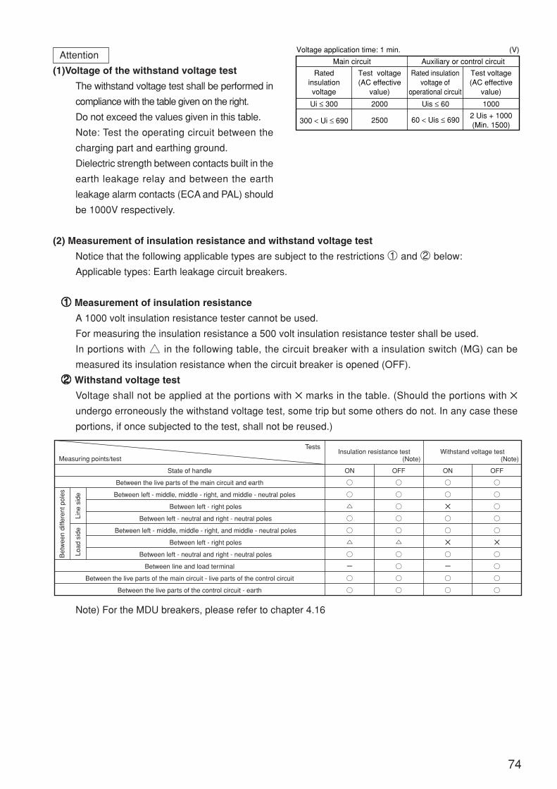
Attention
(1)Voltage of the withstand voltage test
The withstand voltage test shall be performed in
compliance with the table given on the right.
Do not exceed the values given in this table.
Note: Test the operating circuit between the
charging part and earthing ground.
Dielectric strength between contacts built in the
earth leakage relay and between the earth
leakage alarm contacts (ECA and PAL) should
be 1000V respectively.
(2) Measurement of insulation resistance and withstand voltage test
Notice that the following applicable types are subject to the restrictions 1 and 2 below:
Applicable types: Earth leakage circuit breakers.
11111 Measurement of insulation resistance
A 1000 volt insulation resistance tester cannot be used.
For measuring the insulation resistance a 500 volt insulation resistance tester shall be used.
In portions with a in the following table, the circuit breaker with a insulation switch (MG) can be
measured its insulation resistance when the circuit breaker is opened (OFF).
22222 Withstand voltage test
Voltage shall not be applied at the portions with marks in the table. (Should the portions with
undergo erroneously the withstand voltage test, some trip but some others do not. In any case these
portions, if once subjected to the test, shall not be reused.)
Main circuit Auxiliary or control circuit
Ratedinsulationvoltage
Test voltage(AC effective
value)
Rated insulationvoltage of
operational circuit
Test voltage(AC effective
value)
Ui ≤ 300 2000
2500
Uis ≤ 60
60 < Uis ≤ 690
1000
2 Uis + 1000(Min. 1500)
300 < Ui ≤ 690
Voltage application time: 1 min. (V)
74
Note) For the MDU breakers, please refer to chapter 4.16
Tests
Measuring points/test
State of handle
Between the live parts of the main circuit and earth
Between left - middle, middle - right, and middle - neutral poles
Between left - right poles
Between left - neutral and right - neutral poles
Between left - middle, middle - right, and middle - neutral poles
Between left - right poles
Between left - neutral and right - neutral poles
Between line and load terminal
Between the live parts of the main circuit - live parts of the control circuit
Between the live parts of the control circuit - earth
ON OFF ON OFF
Line
sid
eLo
ad s
ide
Bet
wee
n di
ffere
nt p
oles
Insulation resistance test Withstand voltage test(Note)(Note)
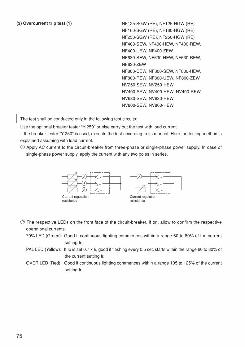
NF125-SGW (RE), NF125-HGW (RE)
NF160-SGW (RE), NF160-HGW (RE)
NF250-SGW (RE), NF250-HGW (RE)
NF400-SEW, NF400-HEW, NF400-REW,
NF400-UEW, NF400-ZEW
NF630-SEW, NF630-HEW, NF630-REW,
NF630-ZEW
NF800-CEW, NF800-SEW, NF800-HEW,
NF800-REW, NF800-UEW, NF800-ZEW
NV250-SEW, NV250-HEW
NV400-SEW, NV400-HEW, NV400-REW
NV630-SEW, NV630-HEW
NV800-SEW, NV800-HEW
The test shall be conducted only in the following test circuits:
Use the optional breaker tester “Y-250” or else carry out the test with load current.
If the breaker tester “Y-250” is used, execute the test according to its manual. Here the testing method is
explained assuming with load current.
1 Apply AC current to the circuit-breaker from three-phase or single-phase power supply. In case of
single-phase power supply, apply the current with any two poles in series.
2 The respective LEDs on the front face of the circuit-breaker, if on, allow to confirm the respective
operational currents.
70% LED (Green): Good if continuous lighting commences within a range 60 to 80% of the current
setting Ir.
PAL LED (Yellow): If Ip is set 0.7 x Ir, good if flashing every 0.5 sec starts within the range 60 to 80% of
the current setting Ir.
OVER LED (Red): Good if continuous lighting commences within a range 105 to 125% of the current
setting Ir.
75
A
A
A
A
Current regulationresistance
Current regulationresistance
(3) Overcurrent trip test (1)
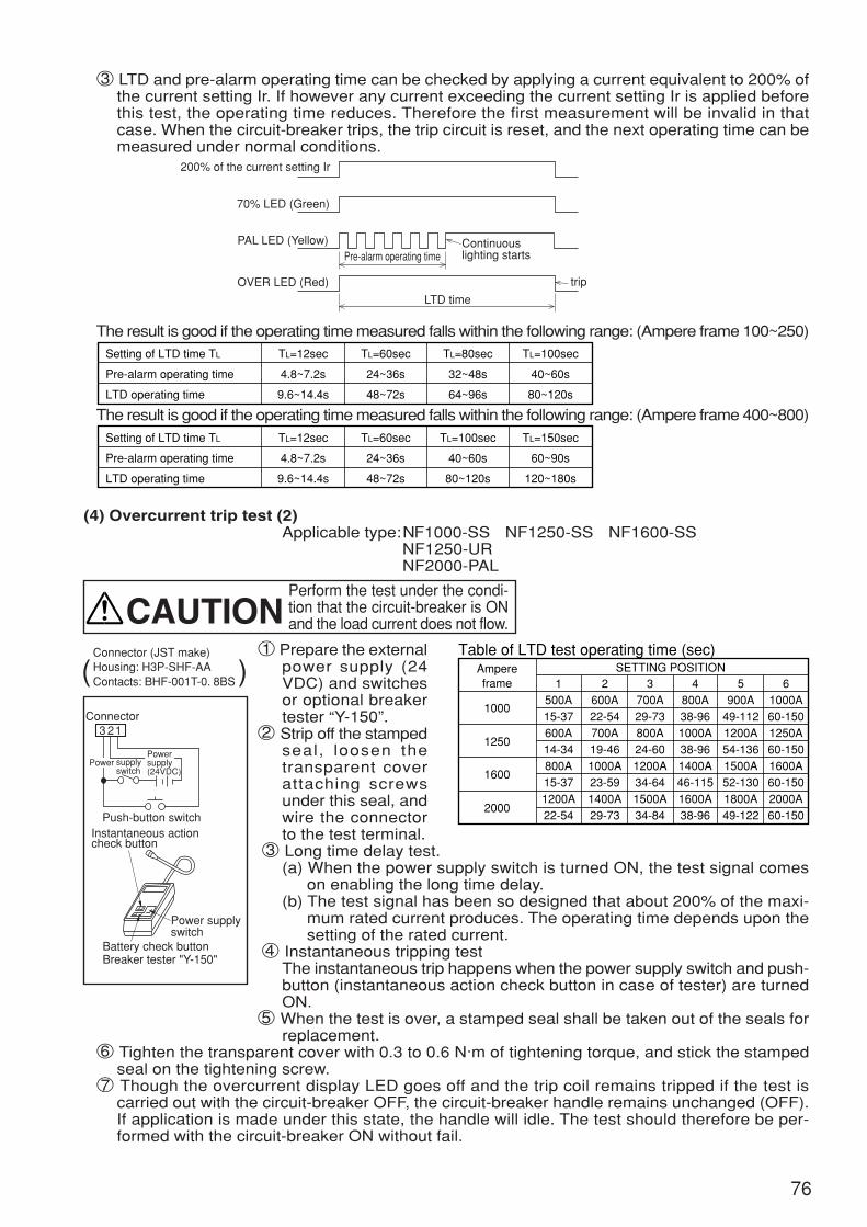
76
3 LTD and pre-alarm operating time can be checked by applying a current equivalent to 200% ofthe current setting Ir. If however any current exceeding the current setting Ir is applied beforethis test, the operating time reduces. Therefore the first measurement will be invalid in thatcase. When the circuit-breaker trips, the trip circuit is reset, and the next operating time can bemeasured under normal conditions.
The result is good if the operating time measured falls within the following range: (Ampere frame 100~250)
The result is good if the operating time measured falls within the following range: (Ampere frame 400~800)
(4) Overcurrent trip test (2)Applicable type: NF1000-SS NF1250-SS NF1600-SS
NF1250-UR NF2000-PAL
1 Prepare the externalpower supply (24VDC) and switchesor optional breakertester “Y-150”.
2 Strip off the stampedseal, loosen thetransparent coverattaching screwsunder this seal, andwire the connectorto the test terminal.
3 Long time delay test.(a) When the power supply switch is turned ON, the test signal comes
on enabling the long time delay.(b) The test signal has been so designed that about 200% of the maxi-
mum rated current produces. The operating time depends upon thesetting of the rated current.
4 Instantaneous tripping testThe instantaneous trip happens when the power supply switch and push-button (instantaneous action check button in case of tester) are turnedON.
5 When the test is over, a stamped seal shall be taken out of the seals forreplacement.
6 Tighten the transparent cover with 0.3 to 0.6 N·m of tightening torque, and stick the stampedseal on the tightening screw.
7 Though the overcurrent display LED goes off and the trip coil remains tripped if the test iscarried out with the circuit-breaker OFF, the circuit-breaker handle remains unchanged (OFF).If application is made under this state, the handle will idle. The test should therefore be per-formed with the circuit-breaker ON without fail.
200% of the current setting Ir
70% LED (Green)
PAL LED (Yellow)
OVER LED (Red)
LTD time
trip
Continuouslighting startsPre-alarm operating time
Setting of LTD time TL
Pre-alarm operating time
LTD operating time
TL=12sec
4.8~7.2s
9.6~14.4s
TL=60sec
24~36s
48~72s
TL=80sec
32~48s
64~96s
TL=100sec
40~60s
80~120s
Setting of LTD time TL
Pre-alarm operating time
LTD operating time
TL=12sec
4.8~7.2s
9.6~14.4s
TL=60sec
24~36s
48~72s
TL=100sec
40~60s
80~120s
TL=150sec
60~90s
120~180s
Connector3 21
supplyswitch
Push-button switch
Power supplyswitch
Instantaneous actioncheck button
Battery check buttonBreaker tester "Y-150"
Powersupply(24VDC)
Power
Perform the test under the condi-tion that the circuit-breaker is ONand the load current does not flow.CAUTION
Ampereframe
1000
1250
1600
2000
SETTING POSITIONTable of LTD test operating time (sec)
1500A15-37600A14-34800A15-371200A22-54
2600A22-54700A19-461000A23-591400A29-73
3700A29-73800A24-601200A34-641500A34-84
4800A38-961000A38-961400A46-1151600A38-96
5900A
49-1121200A54-1361500A52-1301800A49-122
61000A60-1501250A60-1501600A60-1502000A60-150
Connector (JST make)Housing: H3P-SHF-AAContacts: BHF-001T-0. 8BS( )
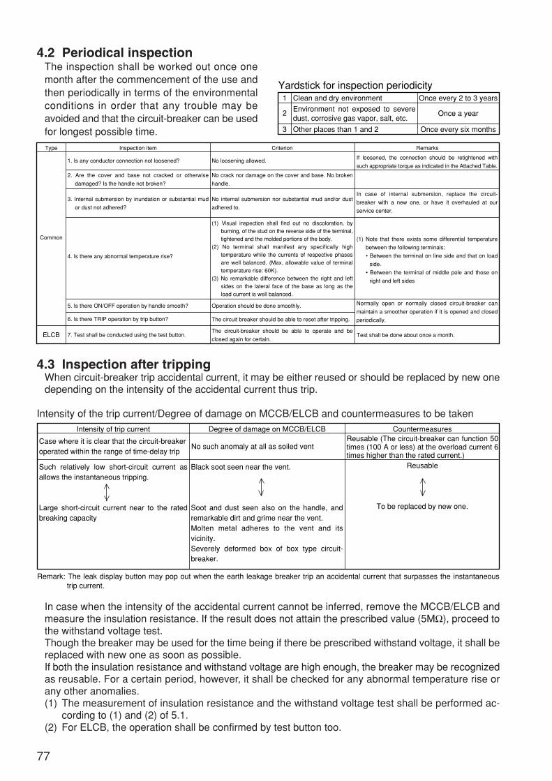
77
4.2 Periodical inspectionThe inspection shall be worked out once onemonth after the commencement of the use andthen periodically in terms of the environmentalconditions in order that any trouble may beavoided and that the circuit-breaker can be usedfor longest possible time.
1 Clean and dry environment
Other places than 1 and 2 Once every six months
Once every 2 to 3 years
Once a yearEnvironment not exposed to severe dust, corrosive gas vapor, salt, etc.
2
3
Yardstick for inspection periodicity
4.3 Inspection after trippingWhen circuit-breaker trip accidental current, it may be either reused or should be replaced by new onedepending on the intensity of the accidental current thus trip.
Intensity of the trip current/Degree of damage on MCCB/ELCB and countermeasures to be taken
In case when the intensity of the accidental current cannot be inferred, remove the MCCB/ELCB andmeasure the insulation resistance. If the result does not attain the prescribed value (5MΩ), proceed tothe withstand voltage test.Though the breaker may be used for the time being if there be prescribed withstand voltage, it shall bereplaced with new one as soon as possible.If both the insulation resistance and withstand voltage are high enough, the breaker may be recognizedas reusable. For a certain period, however, it shall be checked for any abnormal temperature rise orany other anomalies.(1) The measurement of insulation resistance and the withstand voltage test shall be performed ac-
cording to (1) and (2) of 5.1.(2) For ELCB, the operation shall be confirmed by test button too.
Type Inspection item
1. Is any conductor connection not loosened?
4. Is there any abnormal temperature rise?
5. Is there ON/OFF operation by handle smooth?
6. Is there TRIP operation by trip button?
7. Test shall be conducted using the test button.
2. Are the cover and base not cracked or otherwise
damaged? Is the handle not broken?
3. Internal submersion by inundation or substantial mud
or dust not adhered?
No loosening allowed.
Operation should be done smoothly.
The circuit breaker should be able to reset after tripping.
Test shall be done about once a month.
No crack nor damage on the cover and base. No broken
handle.
If loosened, the connection should be retightened with
such appropriate torque as indicated in the Attached Table.
In case of internal submersion, replace the circuit-
breaker with a new one, or have it overhauled at our
service center.
Normally open or normally closed circuit-breaker can
maintain a smoother operation if it is opened and closed
periodically.
(1) Note that there exists some differential temperature
between the following terminals:
• Between the terminal on line side and that on load
side.
• Between the terminal of middle pole and those on
right and left sides
No internal submersion nor substantial mud and/or dust
adhered to.
(1) Visual inspection shall find out no discoloration, by burning, of the stud on the reverse side of the terminal, tightened and the molded portions of the body.
(2) No terminal shall manifest any specifically high temperature while the currents of respective phases are well balanced. (Max. allowable value of terminal temperature rise: 60K).
(3) No remarkable difference between the right and left sides on the lateral face of the base as long as the load current is well balanced.
The circuit-breaker should be able to operate and be
closed again for certain.
Criterion Remarks
Common
ELCB
Intensity of trip current Degree of damage on MCCB/ELCB Countermeasures
No such anomaly at all as soiled ventReusable (The circuit-breaker can function 50 times (100 A or less) at the overload current 6 times higher than the rated current.)
Case where it is clear that the circuit-breakeroperated within the range of time-delay trip
Such relatively low short-circuit current as allows the instantaneous tripping.
Large short-circuit current near to the rated breaking capacity
Remark: The leak display button may pop out when the earth leakage breaker trip an accidental current that surpasses the instantaneous trip current.
Black soot seen near the vent.
Soot and dust seen also on the handle, and remarkable dirt and grime near the vent.Molten metal adheres to the vent and its vicinity.Severely deformed box of box type circuit-breaker.
Reusable
To be replaced by new one.
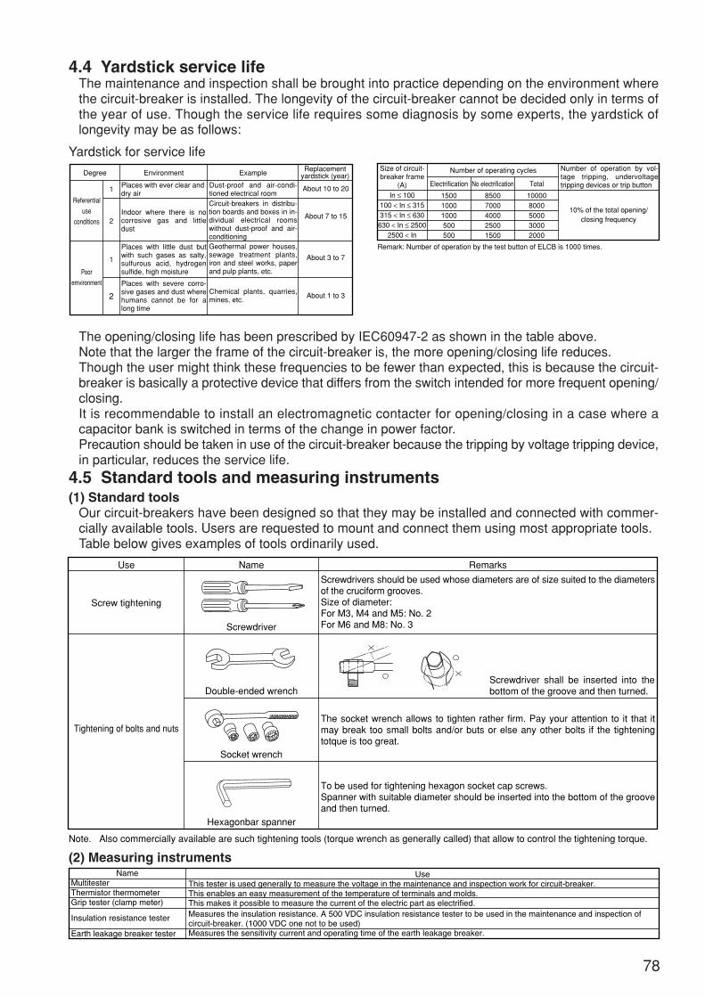
78
4.4 Yardstick service lifeThe maintenance and inspection shall be brought into practice depending on the environment wherethe circuit-breaker is installed. The longevity of the circuit-breaker cannot be decided only in terms ofthe year of use. Though the service life requires some diagnosis by some experts, the yardstick oflongevity may be as follows:
Yardstick for service life
The opening/closing life has been prescribed by IEC60947-2 as shown in the table above.Note that the larger the frame of the circuit-breaker is, the more opening/closing life reduces.Though the user might think these frequencies to be fewer than expected, this is because the circuit-breaker is basically a protective device that differs from the switch intended for more frequent opening/closing.It is recommendable to install an electromagnetic contacter for opening/closing in a case where acapacitor bank is switched in terms of the change in power factor.Precaution should be taken in use of the circuit-breaker because the tripping by voltage tripping device,in particular, reduces the service life.
4.5 Standard tools and measuring instruments(1) Standard tools
Our circuit-breakers have been designed so that they may be installed and connected with commer-cially available tools. Users are requested to mount and connect them using most appropriate tools.Table below gives examples of tools ordinarily used.
Degree Environment Example
Places with ever clear anddry air
Chemical plants, quarries, mines, etc.
Dust-proof and air-condi-tioned electrical room
Replacementyardstick (year)
About 10 to 20
About 7 to 15
About 3 to 7
About 1 to 3
Indoor where there is no corrosive gas and little dust
Places with little dust but with such gases as salty, sulfurous acid, hydrogen sulfide, high moisture
Geothermal power houses, sewage treatment plants, iron and steel works, paper and pulp plants, etc.
Circuit-breakers in distribu-tion boards and boxes in in-dividual electrical rooms without dust-proof and air-conditioning
Places with severe corro-sive gases and dust where humans cannot be for a long time
Referential
use
conditions
Poor
emvironment
1
2
1
2
Size of circuit-breaker frame
(A)
Remark: Number of operation by the test button of ELCB is 1000 times.
Number of operation by vol-tage tripping, undervoltage tripping devices or trip button
10% of the total opening/closing frequency
Number of operating cycles
In ≤ 100100 < In ≤ 315315 < In ≤ 630630 < In ≤ 2500
2500 < In
Electrification
150010001000500500
No electrification
85007000400025001500
Total
100008000500030002000
Use Name Remarks
Screwdrivers should be used whose diameters are of size suited to the diameters of the cruciform grooves.Size of diameter:For M3, M4 and M5: No. 2For M6 and M8: No. 3
The socket wrench allows to tighten rather firm. Pay your attention to it that it may break too small bolts and/or buts or else any other bolts if the tightening totque is too great.
To be used for tightening hexagon socket cap screws.Spanner with suitable diameter should be inserted into the bottom of the groove and then turned.
Screwdriver shall be inserted into the bottom of the groove and then turned.
Screwdriver
Double-ended wrench
Socket wrench
Hexagonbar spanner
Note. Also commercially available are such tightening tools (torque wrench as generally called) that allow to control the tightening torque.
Screw tightening
Tightening of bolts and nuts
(2) Measuring instrumentsName
MultitesterThermistor thermometerGrip tester (clamp meter)
Insulation resistance tester
Earth leakage breaker tester
UseThis tester is used generally to measure the voltage in the maintenance and inspection work for circuit-breaker.This enables an easy measurement of the temperature of terminals and molds.This makes it possible to measure the current of the electric part as electrified.Measures the insulation resistance. A 500 VDC insulation resistance tester to be used in the maintenance and inspection ofcircuit-breaker. (1000 VDC one not to be used)Measures the sensitivity current and operating time of the earth leakage breaker.

79
5. Troubleshooting5.1 Troubleshooting for circuit-breaker proper (MCCB/ELCB)
Trouble Cause
Foreign matter in switching mechanism
No resetting
Fusion of contact due to excessive interruptive current
Excessive operation power
Excessive shock from exterior
Excessive tightening torque (tighten with 3 to 4.5 kg-cm of torque)
Load current strained with much high component
Rather small measurements by error of measuring instrument due to distorted current
Insulating material mingled between contacts
Corrosion by infiltrating rain water, etc.
Countermeasure
Foreign matters to be removed
To be reset once again
See below
To be replaced with new one, Voltage trip to be replaced by electric operation
To be replaced with new one
To be returned for repairing
To be excited
Wait until the bimetal is cooled down
To be returned for repairing
To be replaced by new one
To be replaced by circuit-breaker with large breaking capacity
Handle to be replaced
Handle to be replaced
Revision of positional relationship
To be replaced with new one
To be replaced with new one
To be replaced by new one with larger breaking capacity
To be replaced with new one
Foreign matter to be removed (with removable cover)
To be returned for repairing (with unremovable cover)
Closing impossible
Operating while in use
Short-circuit on line side
(*) Resetting impossible
Tripping impossible
OFF impossible
Resetting impossible
Resetting time has not elapsed
Breakage and/or fatigue of the
switching spring
Deviation of applied frequency (thermal-
adjustable electromagnetic type 800AF or higher)
Poor positional relationship between the external handle and the
circuit-breaker
Transmission was made with antenna of transceiver (5W or higher)
closely mounted on the electronic MCCB and earth leakage breaker
Wear due to trip endurance
Poor reset mechanism
Non-excitation of undervoltage coil
Fused conductive portion
Large consumption of contact
Too high an ambient temperature
Too high a temperature rise
Exothermic reaction due to repeated starting current
Too long a starting time
Poor tightening
Contact heavily consumed
Increased contact resistance
Erroneous action while
starting
Electronic
type
MCCB
Troublesome operation
under normal load
Overcurrent
display
LED is on
Instantaneous action
during starting
Breakage of rated changeover screw
See below (*)
Incessant use of voltage trip operation
End of service life
Poor adjustment
Carelessness
Breakage by initial trouble
End of service life
Excessive interrupting current
Short-circuit current cut off. End of service life
Application of overcurrent
Board hermetically closed
Loosened connection to terminal
Erroneous selection (frequency)
Erroneous selection
Erroneous selection
Poor maintenance
End of service life
Tripping of backup circuit-breakerToo low a current for instanta-
neous tripping of backup breaker
Too high a temperature on
the terminal side
Exothermic reaction of the
tightened portion of stud
No tripping with over
current
Overcurrent display LED doesnot come on. Or, though itcomes on, it goes off sonnerthan normal.
Overcurrent display LED comeson and goes off after prescribedtime. But, no tripping.
Too high a temperature on
the lateral side of the
mould
Intrusion of rust and dust
Erroneous selection (temperature correction)
Abn
orm
al o
pera
tion
Bro
ken
hand
leP
oor
elec
trifi
catio
nT
roub
leso
me
oper
atio
n
To be returned for repairing
Rating selection to be changed
Ventilation
Retighten
To be replaced with circuit-breaker of suitable frequency
Distortion factor to be decreased by reactor Selection of rating to be changed
To be measured correctly by a meter with true effective value, and correct selection of rating
Correct the setting of rated current
Correct retightening of the rated current changeover screw with tightening torque: 3 to 4.5 kg-cm
To be returned for repairing
To be replaced by a unit with higher rating
To be replaced by a unit with higher rating
To be replaced by new one
Foreign matters to be removed
Suitable frequency to be selected To be changed into thermal type.
Distortion factor to be decreased by reactor Selection of rating to be changed
To be measured with a measuring instrument
Retighten
Reassemble the stud
Groove to be provided
To be replaced by a unit with lower rating
Suitable frequency to be selected
Motor to be repaired
To be fully restored
Circuit to be checked to remove the cause
Cause to be removed To be replaced with new one
Cause to be removed To be replaced with new one
Cause to be removed To be replaced with new one
Retighten
Transceiver to be used at a distance at least 1 m from the electronic
MCCB
Instantaneous electromagnetic switch to be lowered
Raise the electromagnetic setting of backup breaker or change the rating
Electromagnetic setting to be change or the unit to be replaced by one with higher rating
Electromagnetic setting to be change or the unit to be replaced by one with higher rating
Electromagnetic setting to be change or the unit to be replaced by one with higher rating
Electromagnetic setting to be change or the unit to be replaced by one with higher rating
Too small a setting of rated current
Tightening forgotten of the changeover screw of rated current
Failure of rated current changeover portion
Too high a starting current
Too high a starting rush current
Transient current when changing delta connection to star one. Transient current due to reversible operation
Rush current at the time of instantaneous restart
Rare short-circuit of motor
Bimetal reset incomplete after instantaneous tripping
Shift from the short-circuit of another conductor
Accumulated dust
Fall of conductor on line side
Complete electromagnetic type used in high frequency (400 Hz, for instance)
Load current distorted containing much high frequency component
Groove machining forgotten for reduction of eddy-current exothermic reaction of rear-connected type iron mount plate (400AF or higher)
Poor contact between the conductive portion of stud and the body terminal
Loosened stud
Too high a rated current selected
The battery of breaker tester has come at the end of its service life.
Poor tripping mechanism
Wrong frequency applied
Erroneous measurement dependent on feeling
Abnormal current running simultaneously with closing (short-circuit closing)
Tem
pera
ture
ris
eN
o op
erat
ion
No
oper
atio
n w
ithte
ster
(ele
ctro
nic
MC
CB)
Battery to be replaced.
To be returned for repairing.
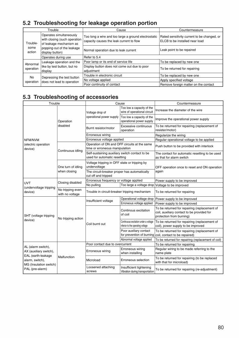
80
5.2 Troubleshooting for leakage operation portionTrouble Cause
Normal operation due to leak current
Refer to 5.4
Operates simultaneouslywith closing (such operationof leakage mechanism aspopping-out of the leakagedisplay button)
Operates during use
Depressing the test buttondoes not lead to operation
Leakage operation and thelike by test button, but nodisplay
Poor lamp or its end of service life
Trouble in electronic circuitNo voltage appliedPoor continuity of contact
Too long a wire and too large a ground electrostaticcapacity causes the leak current to flow
Display button does not come out due to poor adjustment
Countermeasure
Leak point to be repaired
To be replaced by new one
To be replaced by new oneApply specified voltageRemove foreign matter on the contact
To be returned for repairing
Rated sensitivity current to be changed, orELCB to be installed near load
Trouble-someaction
Abnormaloperation
Nooperation
5.3 Troubleshooting of accessoriesTrouble Cause Countermeasure
Increase the diameter of the wire
Improve the operational power supply
Regularize the wiringRegular operational voltage to be applied
Power supply to be improvedVoltage to be improved
To be returned for repairing
To be returned for repairing (replacement of coil)
To be returned for repairing (re-adjustment)
To be returned for repairing
Power supply to be improvedPower supply to be improved
To be returned for repairing (replacement of coil, auxiliary contact to be provided for protection from burning)
Push button to be provided with interlock
To be returned for repairing (replacement of resister/motor)
The contact for automatic resetting to be used as that for alarm switch
OFF operation once to reset and ON operation again
To be returned for repairing (replacement of coil), power supply to be improved
To be returned for repairing (replacement of coil, contact to be repaired)
Regular wiring to be made referring to the name plate
To be returned for repairing (to be replaced with that for microload)
Operationdisabled
NFM/NVM(electric operationdevice)
UVT(undervoltage trippingdevice)
SHT (voltage trippingdevice)
AL (alarm switch),AX (auxiliary switch),EAL (earth-leakagealarm, switch),MG (Insulation switch)PAL (pre-alarm)
Voltage drop ofoperational power supply
Too low a capacity of thewire of operational circuit
Too low a capacity of theoperational power supply
Excessive continuousoperation
Continuous excitation under a voltageinferior to the operating voltage
Poor auxiliary contactfor prevention of burning
Erroneous wiringwhen installing
Insufficient tighteningVibration during transportation
Loosened attachingscrews
Continous excitationof coil
Operation of ON and OFF circuits at the sametime or erroneous manipulation
Self-sustaining auxiliary switch contact to beused for automatic resetting
Voltage tripping in OFF state or tripping byundervoltage
The circuit-breaker proper has automaticallycut off and tripped
Continuous idling
Closing disabled
Burnt resistor/motor
No pulling
Insufficient voltage
Coil burnt out
Erroneous wiring
MicroloadMalfunction
No tripping action
Too large a voltage drop
Operational voltage dropErroneous voltage applied
Abnormal voltage applied
Erroneous selection
Erroneous wiringErroneous voltage applied
Erroneous frequency or voltage applied
Trouble in circuit-breaker tripping mechanism
Poor contact due to overcurrent
One turn of idlingwhen closing
No tripping evenwith no voltage
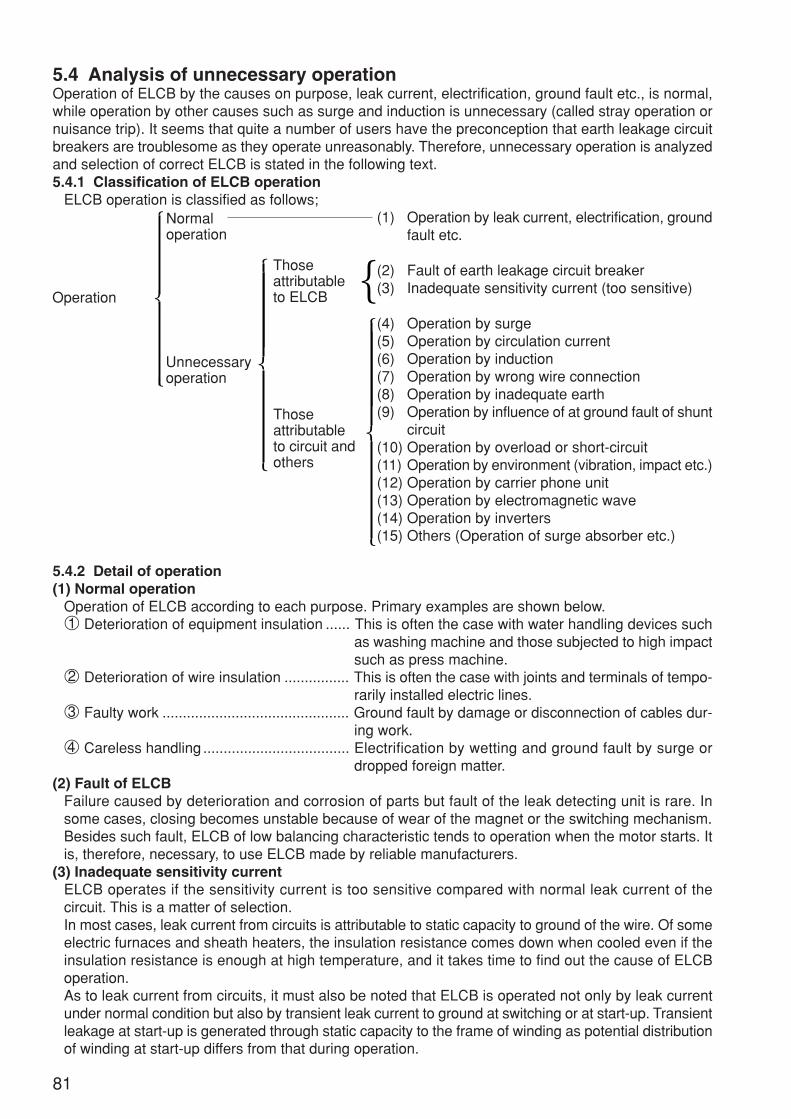
81
5.4 Analysis of unnecessary operationOperation of ELCB by the causes on purpose, leak current, electrification, ground fault etc., is normal,while operation by other causes such as surge and induction is unnecessary (called stray operation ornuisance trip). It seems that quite a number of users have the preconception that earth leakage circuitbreakers are troublesome as they operate unreasonably. Therefore, unnecessary operation is analyzedand selection of correct ELCB is stated in the following text.5.4.1 Classification of ELCB operation
ELCB operation is classified as follows;(1) Operation by leak current, electrification, ground
fault etc.
(2) Fault of earth leakage circuit breaker(3) Inadequate sensitivity current (too sensitive)
(4) Operation by surge(5) Operation by circulation current(6) Operation by induction(7) Operation by wrong wire connection(8) Operation by inadequate earth(9) Operation by influence of at ground fault of shunt
circuit(10) Operation by overload or short-circuit(11) Operation by environment (vibration, impact etc.)(12) Operation by carrier phone unit(13) Operation by electromagnetic wave(14) Operation by inverters(15) Others (Operation of surge absorber etc.)
5.4.2 Detail of operation(1) Normal operation
Operation of ELCB according to each purpose. Primary examples are shown below.1 Deterioration of equipment insulation ...... This is often the case with water handling devices such
as washing machine and those subjected to high impactsuch as press machine.
2 Deterioration of wire insulation ................ This is often the case with joints and terminals of tempo-rarily installed electric lines.
3 Faulty work .............................................. Ground fault by damage or disconnection of cables dur-ing work.
4 Careless handling .................................... Electrification by wetting and ground fault by surge ordropped foreign matter.
(2) Fault of ELCBFailure caused by deterioration and corrosion of parts but fault of the leak detecting unit is rare. Insome cases, closing becomes unstable because of wear of the magnet or the switching mechanism.Besides such fault, ELCB of low balancing characteristic tends to operation when the motor starts. Itis, therefore, necessary, to use ELCB made by reliable manufacturers.
(3) Inadequate sensitivity currentELCB operates if the sensitivity current is too sensitive compared with normal leak current of thecircuit. This is a matter of selection.In most cases, leak current from circuits is attributable to static capacity to ground of the wire. Of someelectric furnaces and sheath heaters, the insulation resistance comes down when cooled even if theinsulation resistance is enough at high temperature, and it takes time to find out the cause of ELCBoperation.As to leak current from circuits, it must also be noted that ELCB is operated not only by leak currentunder normal condition but also by transient leak current to ground at switching or at start-up. Transientleakage at start-up is generated through static capacity to the frame of winding as potential distributionof winding at start-up differs from that during operation.
Normaloperation
Thoseattributableto ELCB
Thoseattributableto circuit andothers
Unnecessaryoperation
Operation
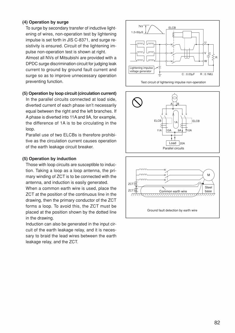
82
(4) Operation by surgeTo surge by secondary transfer of inductive light-ening of wires, non-operation test by lighteningimpulse is set forth in JIS C-8371, and surge re-sistivity is ensured. Circuit of the lightening im-pulse non-operation test is shown at right.Almost all NVs of Mitsubishi are provided with aDPDC surge discrimination circuit for judging leakcurrent to ground by ground fault current andsurge so as to improve unnecessary operationpreventing function.
(5) Operation by loop circuit (circulation current)In the parallel circuits connected at load side,diverted current of each phase isn’t necessarilyequal between the right and the left branches. IfA phase is diverted into 11A and 9A, for example,the difference of 1A is to be circulating in theloop.Parallel use of two ELCBs is therefore prohibi-tive as the circulation current causes operationof the earth leakage circuit breaker.
(5) Operation by inductionThose with loop circuits are susceptible to induc-tion. Taking a loop as a loop antenna, the pri-mary winding of ZCT is to be connected with theantenna, and induction is easily generated.When a common earth wire is used, place theZCT at the position of the continuous line in thedrawing, then the primary conductor of the ZCTforms a loop. To avoid this, the ZCT must beplaced at the position shown by the dotted linein the drawing.Induction can also be generated in the input cir-cuit of the earth leakage relay, and it is neces-sary to braid the lead wires between the earthleakage relay, and the ZCT.
7kV ELCB
Lightening impulsevoltage generator
Test circuit of lightening impulse non-operation
U
V
W
CR
1.2×50µS
C : 0.03µF R : 0.1MΩ
A B
ELCBELCB 1A
Load
Parallel circuits
10A11A 10A
20A
9A
ZCT
ZCT Common earth wire
Ground fault detection by earth wire
Steelbase
M

83
(7) Operation by wrong wire connectionFailure in passing the neutral wire through the ZCTfor the lines of single phase 3-wire or 3 phase 4-wire is a simple mistake. In this case, the ELCB isoperated by single phase load current.
On the other hand, the common earth wire shallnot go through the ZCT as it can be cause mal-function at leakage.
(8) Operation by inadequate earthThough the wire is grounded at the earth side,the wire shall not be earthed at the load side. Bythe voltage of voltage drop in the line at the earthside, a part of the load current is diverted asshown by I’T, and the ELCB is operated.
(9) Operation of sound circuit at ground fault of shunt circuitNot only the ELCB in the ground fault circuit but also the one in the sound circuit is operated in some casesthrough the circuit as illustrated below. This can be avoided by keeping sensitive current suitably for the leakcurrent by static capacity to ground.
(10) Operation by overload and short-circuitIt is natural that the devices having overload or short-circuit operation elements operate at short-circuit. However, ELCB is commonlyused for many other purposes, and it tends to be overlooked that ELCB operate even at an overload and a short-circuit failure.Moreover, even the one dedicated to ground fault is sometimes operated by an excessive overload and short-circuit becausebalance performance of ELCB is limited. In these cases, however, overload and short-circuit can be noticed if they are significant.
(11) Environment of vibration, impact, high temperature etc.These factors may be taken almost equal to those of Mitsubishi’s MCCB. Heat resistivity of electronic circuits tends to be fellunreliable. To Mitsubishi’s ELCB, enough allowance is given to ratings of the parts, the parts which can withstand high tempera-ture operation are used, and the ICs incorporating tempereture compensation circuits are used to ensure stable operation evenin varying temperature environment.
ZCT
Wrong wire connection of 3 phase 4-wire lineLoad
ZCT
Wrong connection of common earth wire
M
Common earth wire
I T
I'T
Inadequate double ground
M
Operation of sound circuit by static capacity to ground
Fault circuit
Sound circuit

84
(12) Operation by carrier phone unitMalfunctions of the ELCB can result in some cases when attached to a line provided with a carrier
phone, which enables calls through the power line.
Since the carrier phone forcefully gives high frequency signals (normally 50kHz to 400kHz) between
the line and the ground, the ELCB detects the high frequency signals as if they are leak current and
leads to malfunction. Malfunction or not depends largely on magnitude of the high frequency signals,
high frequency characteristic of the ELCB, and degree of rated sensitive current.
(13) Operation by electromagnetic waveWhen a portable type transceiver is placed near the ELCB at transmission, particularly intense mag-
netic field is generated easily resulting in malfunction. Generally speaking, frequency bands of por-
table type transceivers are 27/28MHz, 50/50MHz, 150MHz, 400MHz, and 900MHz, and the output is
about 0.5 to 5W. It is confirmed that the ELCB is free from any malfunction when different kinds of
transceivers of 5W output are used for transmission being placed at 1m from the ELCB.
(14) Operation by invertersInverters operate many high-frequency components as they turn A.C. power supply to D.C. through
rectification, then turn to A.C. again by switching through transistors.
Increased static capacity to ground sometimes causes malfunctions as the high frequency compo-
nents are kept flowing by the static capacity to ground. To use ELCB in general in an inverter circuit, it
is necessary to select those of lower sensitive current than usual in order avoid unnecessary opera-
tion.
For ground fault detection of high sensitivity in inverter circuit and yet for stable ground fault detection
at both the primary and the secondary sides of the inverters, it is necessary to use an ELCB designed
for higher harmonic earth-leakages and surges, which is hardly affected by high frequency compo-
nents, as the measure against the inverter.
It is also essential to install the ELCB at the primary side of the inverter, and never at the secondary
side.
(15) OthersAs electronic arrangement of load equip-
ment advances, surge absorbers are in-
stalled in the equipment more and more to
protect them against surge. As the surge ab-
sorbers connected to the ground discharge
the surge to the ground, a high leak current
is generated to the ground, for a short time
though, and unnecessary operation of the
ELCB is resulted in some cases.
Most Mitsubishi’s ELCB are provided with a
DPDC surge discriminating circuit for judg-
ing ground fault current by failure such as faulty insulation from leak current to ground by surge, and
improvement in the performance of preventing unnecessary operation is realized even when the surge
absorber is installed between the line and the ground.
Applicable circuit to inverter
Inverter
ELCBIM
1C1 1C2
Surge
Loadequipment
Loadequipment
ELCB
Gapless surgeabsorber
Discherge gaptype absorber
IS
IS
A load equipment is protected by a surge absorber
Leak current to ground through surge absorber
Circuit androute of leakcurrent toground

85
6. After-sales service6.1 Countermeasures to be taken in case of anomaly
Should any anomaly arise while the circuit-breaker is operating, take the following countermeasures:
1 With electrical safety supervisor
If any anomaly occurs, the electrical safety supervisor shall be informed of this anomaly, and nec-
essary inspection shall be worked out based on the instructions given by this supervisor. In case
when the cause is unknown or repairing required, please contact our Service Center or our branches.
2 Without electrical safety supervisor
Immediately contact our Service Center, our branches or the nearest electric work contractor.
6.2 After-sales service systemWe have organized a system responding to any requests from users (inspection, repairing, diagnosis
of degradation). For any detail, do not hesitate to contact us.
Use to be prohibited under abnormal conditions:Continuing to use the circuit-breaker under abnormal conditions may lead to some acci-dents.
CAUTION
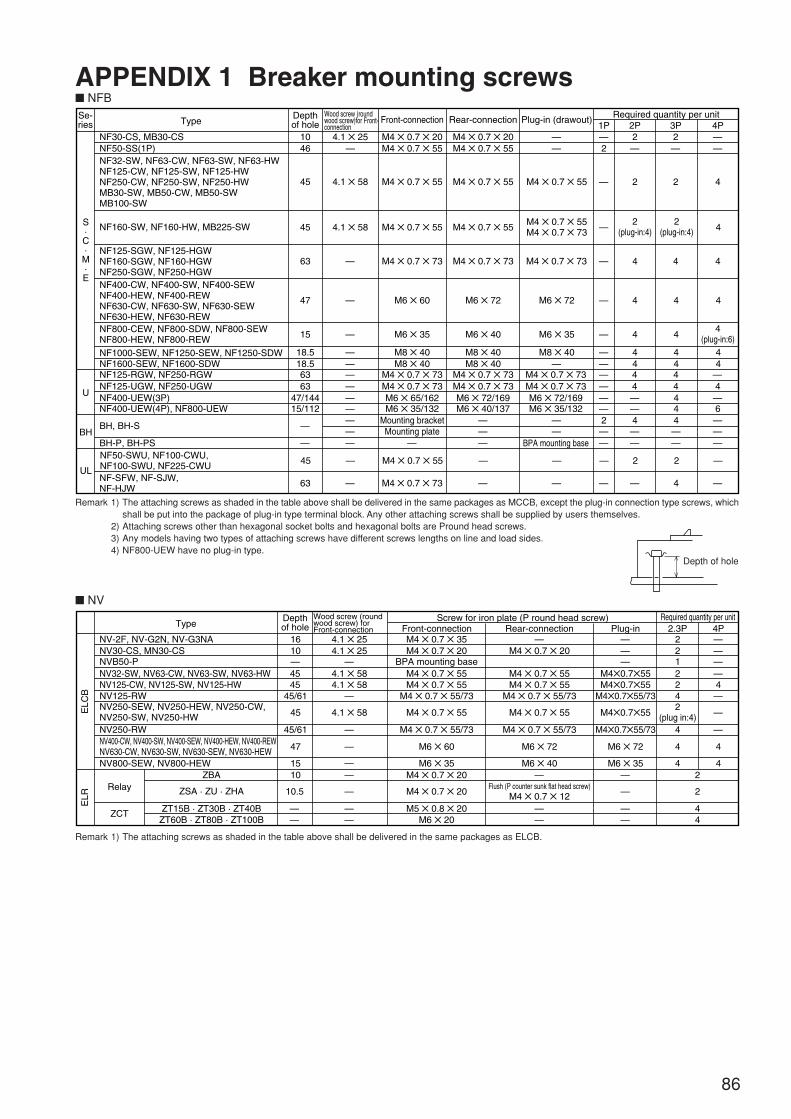
86
APPENDIX 1 Breaker mounting screws NFBSe-ries
Depthof hole
10 4.1 25 M4 0.7 20 M4 0.7 20M4 0.7 55
M4 0.7 55
M4 0.7 55
M4 0.7 73M4 0.7 73M6 72/169M6 40/137
—
——
—
— —
— —
—
—1P—2
—
—
—
—
—
M6 72
M6 40
M8 40
M4 0.7 55
M4 0.7 55M4 0.7 73
M6 72
M6 35
M8 40M8 40
M4 0.7 73M4 0.7 73M6 72/169M6 35/132
BPA mounting base
M4 0.7 55
M4 0.7 55
M4 0.7 55
M4 0.7 73
Mounting plateMounting bracket
M6 35/132
M4 0.7 73M6 65/162
M6 60
M6 35
M8 40M8 40
—
—
—
4.1 58
4.1 58
46
Front-connection Rear-connectionWood screw (roundwood screw)for Front-connection
Type
NF30-CS, MB30-CSNF50-SS(1P)
NF1600-SEW, NF1600-SDW
NF32-SW, NF63-CW, NF63-SW, NF63-HWNF125-CW, NF125-SW, NF125-HW NF250-CW, NF250-SW, NF250-HWMB30-SW, MB50-CW, MB50-SWMB100-SW
NF125-SGW, NF125-HGWNF160-SGW, NF160-HGWNF250-SGW, NF250-HGW
NF800-CEW, NF800-SDW, NF800-SEWNF800-HEW, NF800-REW
NF160-SW, NF160-HW, MB225-SW
NF400-CW, NF400-SW, NF400-SEWNF400-HEW, NF400-REWNF630-CW, NF630-SW, NF630-SEWNF630-HEW, NF630-REW
NF1000-SEW, NF1250-SEW, NF1250-SDW
Plug-in (drawout) Required quantity per unit
NF125-RGW, NF250-RGWNF125-UGW, NF250-UGWNF400-UEW(3P)NF400-UEW(4P), NF800-UEW
BH, BH-S
BH-P, BH-PSBH
UL
U
S·C·M·E
45
45
M4 0.7 73 M4 0.7 73 —M4 0.7 73—63
47
15
18.518.56363
—
—
47/14415/112
—————————
—
——————
—— —
—4——
4
——444
44 4
44
4
——
— —
—
—6—4
—44
2
4
4 4 4
4
4
M4 0.7 55NF50-SWU, NF100-CWU, NF100-SWU, NF225-CWU 45 — — 22
M4 0.7 73NF-SFW, NF-SJW,NF-HJW 63 — — 4
4
2(plug-in:4)
2(plug-in:4)
4(plug-in:6)
2 2 4
4 4 4
— —2 —
3P 4P2P2——
Remark 1) The attaching screws as shaded in the table above shall be delivered in the same packages as MCCB, except the plug-in connection type screws, whichshall be put into the package of plug-in type terminal block. Any other attaching screws shall be supplied by users themselves.
2) Attaching screws other than hexagonal socket bolts and hexagonal bolts are Pround head screws.3) Any models having two types of attaching screws have different screws lengths on line and load sides.4) NF800-UEW have no plug-in type.
NV
Remark 1) The attaching screws as shaded in the table above shall be delivered in the same packages as ELCB.
Depthof hole
—
—
——
—
——
4.1 254.1 25
—4.1 58
M4 0.7 35 —M4 0.7 20
M4 0.7 55
M4 0.7 55
M4 0.7 55/73
M6 72
M6 40—
Flush (P counter sunk flat head screw)M4 0.7 12
——
M4 0.7 20BPA mounting base
M4 0.7 55
M4 0.7 55
M4 0.7 55/73
M6 60
M6 35M4 0.7 20
M5 0.8 20
M4 0.7 20
M6 20
1610—
Front-connection Rear-connection Plug-in
M40.755
M6 72
M6 35
M40.755/73
M40.755
———
Wood screw (roundwood screw) for Front-connection
Type
NV-2F, NV-G2N, NV-G3NANV30-CS, MN30-CSNVB50-PNV32-SW, NV63-CW, NV63-SW, NV63-HWNV125-CW, NV125-SW, NV125-HW
NV250-RWNV400-CW, NV400-SW, NV400-SEW, NV400-HEW, NV400-REWNV630-CW, NV630-SW, NV630-SEW, NV630-HEW
NV250-SEW, NV250-HEW, NV250-CW, NV250-SW, NV250-HW
NV800-SEW, NV800-HEW
Screw for iron plate (P round head screw) Required quantity per unit
ZCT
RelayZBA
ZSA · ZU · ZHA
ZT15B · ZT30B · ZT40BZT60B · ZT80B · ZT100B
ELC
BE
LR
45
2.3P 4P————
—
—
4
4
2212
4.1 58 M4 0.7 55M4 0.7 55 M40.75545 42
2(plug in:4)
4
4
42
2
44
45
45/61
— M4 0.7 55/73M4 0.7 55/73 M40.755/73NV125-RW —445/61
47
1510
10.5
——
4.1 58
—
—
——
Depth of hole
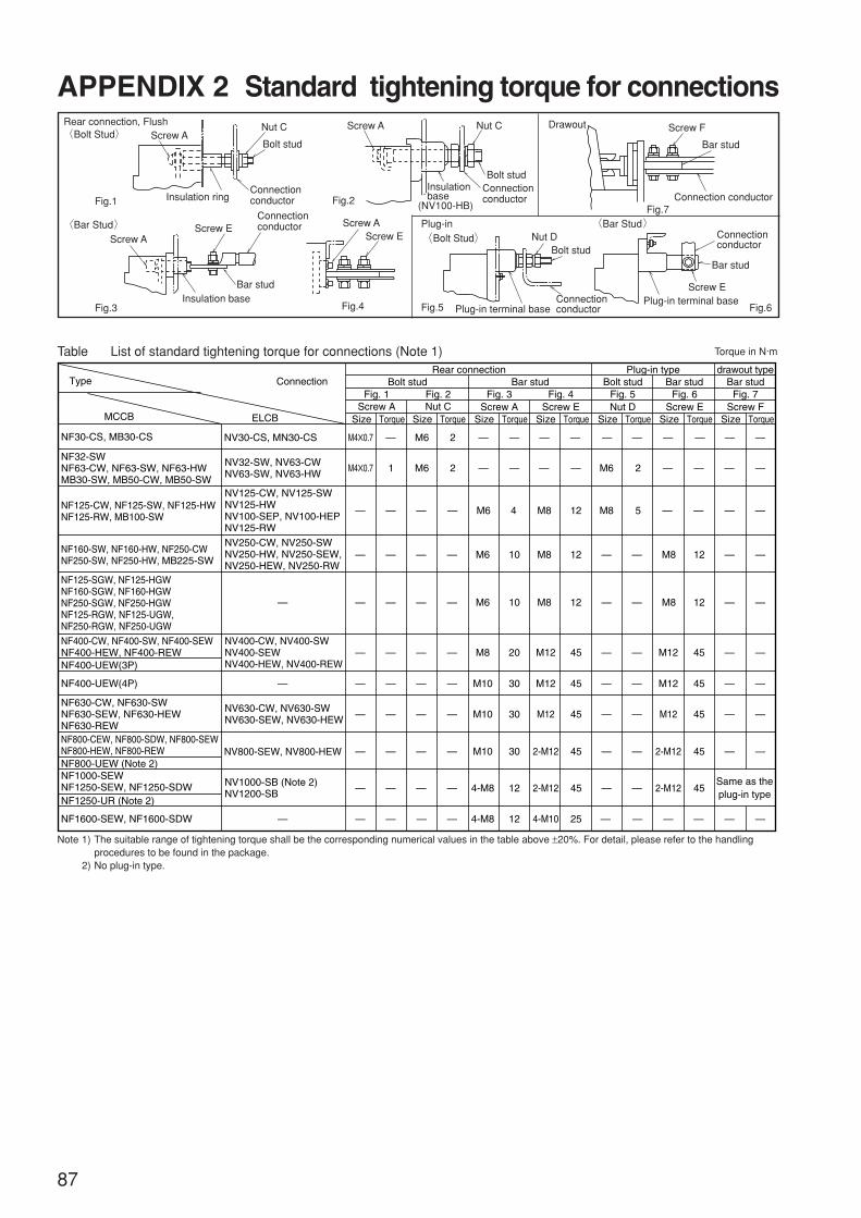
Screw A
Screw A
Screw A Nut C
Bolt stud
Screw A
Rear connection, FlushBolt Stud
Fig.1
Fig.3
Fig.2
Fig.4
Screw EScrew E
Insulation ring
Insulation base
Insulationbase
(NV100-HB)
Connectionconductor
Connectionconductor
Connectionconductor
Nut C
Bolt stud
Bar stud
Bar Stud
87
APPENDIX 2 Standard tightening torque for connections
NF400-UEW(3P)
NF400-UEW(4P)
Rear connectionBolt stud
Fig. 1 Fig. 2Screw A
Size Torque Size Torque Size Torque Size Torque Size Torque Size Torque Size TorqueNut C
Fig. 3 Fig. 4 Fig. 5 Fig. 6 Fig. 7
Plug-in type drawout type
Screw A Screw E Nut D Screw E Screw F
Bar stud Bolt stud Bar stud Bar studConnection
MCCB
NF30-CS, MB30-CS NV30-CS, MN30-CS
—
—
—
—
—
—
—
—
—
—
—
—
—
—
—
—
— —
—
—
— — — ———
— — — — — — — —
—
— —
—
—
—
—
—
—
—
—
—
—
—
—
—
—
—
—
—
—
—
—
—
—
—
—
—
—
—
—
—
—
M6
M6 M8
M8
M8
M10
M10
M10
4-M8
4-M8
M12
M12
M12
2-M12
2-M12
M8
M12
M12
M12
2-M12
2-M12
4-M10
M6
M6
M40.7 1 2
4 12
1210
20
30
30
30
12
12
45
45
45
45
45
45
12
45
45
45
45Same as theplug-in type
25
M8
M6
5
2M40.7
— — — — ———— — —
NF400-CW, NF400-SW, NF400-SEWNF400-HEW, NF400-REW
NF630-CW, NF630-SWNF630-SEW, NF630-HEWNF630-REW
NF800-UEW (Note 2)
NF800-CEW, NF800-SDW, NF800-SEWNF800-HEW, NF800-REW
NF1250-UR (Note 2)
NF1600-SEW, NF1600-SDW
NF1000-SEWNF1250-SEW, NF1250-SDW
NF32-SWNF63-CW, NF63-SW, NF63-HWMB30-SW, MB50-CW, MB50-SW
NV32-SW, NV63-CWNV63-SW, NV63-HW
NV400-CW, NV400-SWNV400-SEWNV400-HEW, NV400-REW
NV125-CW, NV125-SWNV125-HWNV100-SEP, NV100-HEPNV125-RW
NV250-CW, NV250-SWNV250-HW, NV250-SEW,NV250-HEW, NV250-RW
NV630-CW, NV630-SWNV630-SEW, NV630-HEW
NV1000-SB (Note 2)NV1200-SB
NF125-CW, NF125-SW, NF125-HWNF125-RW, MB100-SW
NF160-SW, NF160-HW, NF250-CWNF250-SW, NF250-HW, MB225-SW
Type
ELCB
NV800-SEW, NV800-HEW
————
—
— — — — — — —M6 M8 M81210 12
NF125-SGW, NF125-HGWNF160-SGW, NF160-HGWNF250-SGW, NF250-HGWNF125-RGW, NF125-UGW,NF250-RGW, NF250-UGW
—
—
—
—
—
2
Table List of standard tightening torque for connections (Note 1) Torque in N·m
Note 1) The suitable range of tightening torque shall be the corresponding numerical values in the table above ±20%. For detail, please refer to the handlingprocedures to be found in the package.
2) No plug-in type.
Fig.7
Screw F
Connection conductor
Bar stud
Drawout
Nut DBolt stud
Fig.5 Fig.6
Screw E
Plug-in terminal basePlug-in terminal baseConnection
conductor
Connectionconductor
Bar stud
Plug-inBolt Stud
Bar Stud

88
APPENDIX 3 Operating force of handle
3
NV250-CW
NV400-CW
Type PolesOperational force of handle, N · m
ON
0.45
1.05
1.35
1.31
0.83
2.1
2.1
10.2
7.8
15.5
2.9
13.5
0.15
1.25
1.55
1.53
0.99
3
3
8.4
6.15
12
0.03 47 20
32 58
33 57
38 54
38 54
49 106
42.5 67.5
49 85
49 106
84 106
42.5 67.5
42.5 67.5
146 106
146 106
47 20
2.5
3.1
4.93
3.15
OFF Reset A B
Dimensions (mm)
2, 3
2
3
NF30-CS, MB30-CS
NF125-SW, NF125-HW, NF125-CW, MB100-SW
NF250-SW, NF250-CW, MB225-SW, NF160-SW
NV32-SW, NV63-SW
NV800-SEW, NV800-HEW
NF250-HW, NF250-HEW, NF160-HW
NF400-SW, NF400-SEW, NF400-HEW, NF400-REWNF630-CW, NF630-SW, NF630-SEW, NF630-HEWNF630-REW
NF32-SW, NF63-SW, NF63-HW, NF63-CWMB30-SW, MB50-SW, MB50-CW
2.9
3.3
2.9
2.7
3.1
2.7
2.9
3.3
2.9
2, 3
4
3
NF125-SGW, NF125-HGW, NF-SFW (110A and less)
NF-SFW (125A and more), NF-SJW, NF-HJW
NF800-CEW, NF800-SDW, NF800-SEW, NF800-HEWNF800-REW
4.4
4.6
4.4
3.9
4.0
3.9
3.9
4.5
3.9
2, 3
4
3
NF250-SGW, NF250-HGW
NF400-CW
NF1000-SEW, NF1250-SEW, NF1250-SDW, NF1600-SEW, NF1600-SDW
NF125-RGW, NF125-UGW
NF250-RGW, NF250-UGW
NF400-UEW
NF800-UEW
NV30-CS
NV63-CW
NV63-HW
NV125-SW, NV125-HW, NV125-CW
NV125-RW
NV250-SW, NV250-SEW
NV400-SW, NV400-SEW, NV400-HEW, NV400-REWNV630-CW, NV630-SW, NV630-SEW, NV630-HEW
NV250-HW, NV250-HEW
NV250-RW
2
3
3.6
3.3
3.3
3.1
3.5
3.3NF160-SGW, NF160-HGW
2, 3
4
3
3
3
3
3
3
3
2, 3
2, 3
2, 3
2, 3
3
2, 3
2, 3
3
3
3
3
3
3
3
3
4.4
10.2
13.5
0.45
10.1
2.7
3.9
8.4
12
0.15
5.2
5.2
20
16.1
30
19.4
2.9
3.9
20
30
0.03
1.35
1.31
2.1
2.1
10.2
7.8
13.5
1.55
1.53
3
3
8.4
6.15
12
3.1
4.93
5.2
5.2
20
16.1
30
32
33
38
38
49
49
49
58
57
54
54
106
85
106
MCCB
S·C·M
U
ELCB
The numerical values below represent the measurements resulting from thehandle as pulled horizontally (arrowed direction). B size gives the dimen-sions without those of auxiliary handle.A
B

APPENDIX 4 Service network
89
Country / Region Company Address Telephone
Australia
Belgium
Chile
China
Colombia
Denmark
Egypt
Germany
Greece
Hong Kong
Indonesia
Ireland
Italy
Korea
Laos
Lebanon
Myanmer
Nepal
New Zealand
Norway
Pakistan
Philippines
Poland
Saudi Arabia
Singapore
Slovenia
South Africa
Spain
Sweden
Switzerland
Taiwan
Thailand
The Netherlands
Turkey
U.K.
Uruguay
Venezuela
Vietnam
Mitsubishi Electric Australia Pty. Ltd
Emac S.A.
RHONA S.A.
SHANGHAI SETSUYO TRADING CO.,LTD.
Proelectrico Representaciones S.A.
Louis Poulsen CO. A/S
CAIRO ELECTRICAL GROUP
Drepanias Antonios S.A.
Mitsubishi Electric Automation (Hong Kong) Limited
Mitsubishi Electric Automation (Shanghai) Limited
P.T.SAHABAT INDONESIA.
Mitsubishi Electric Europe B.V. Irish Branch.
Mitsubishi Electric Europe B.V. Italy
Mitsubishi Electric Europe B.V. German Branch.
MITSUBISHI ELECTRIC AUTOMATION KOREA CO., LTD.
SOCIETE LAO IMPORT-EXPORT
COMPTOIR D'ELECTRICITEGENERALE INTERNATIONAL
PEACE MYANMAR ELECTRIC CO., LTD.
Watt & Volt House Co., Ltd.
Melco Sales (N.Z.) Ltd.
SCANELEC AS
Prince Electric Co.
EDISON ELECTRIC INTEGRATED, INC.
MPL Technology Sp zo.o.
CENTER OF ELECTRICAL GOODS
INEA d.o.o.
Circuit Breaker Industries LTD.
Mitsubishi Electric Europe B.V. Spanish Branch.
Euro Energy Components AB
MITSUBISHI ELECTRIC ASIA PTE LTD.
Trielec A G
Setsuyo Enterprise Co., Ltd.
UNITED TRADING & IMPORT CO. LTD.
Imtech Marine & Offshore
GTS
Mitsubishi Electric Europe B.V. UK-Branch.
Fierro Vignoli S.A.
ADESCO C.A.
SA GIANG TECHNO CO., LTD.
348 Victoria Road, Rydalmere, N.S.W. 2116, Australia
Industrialaan 1, B-1702 Groot-Bijgaarden, Belgium.
Vte. Agua Santa 4211 Casilla 30-D (P.O. Box) Viña Del Mar. Chile
Shanghai Everbright Convention & Exhibition CenterRoom2306. Block D. 80, Cao bao Rd., Xuhui District Shanghai, P. R. Chaina
Cra 53 No 29C-73 U.I.C.- Medellin. COLOMBIA.
Geminivej 32, DK-2670 Greve, Denmark.
P.O. BOX: 165-11516, Maglis El-Shaab Cairo-Egypt.
Gothaer Strasse 8, 40880 Ratingen, Germany.
52, ArkadiasSTR.GR 121 32. Peristeri Athens Greece.
10/F Manulife Tower 169 Electric Road North Point. Hong Kong.
JL Muara Karang Selatan Blok A/Utara No.1 kav. NO.11 P.O. Box 5045/Jakarta/11050. Jakarta Indonesia.
Westgate Business Park, IRL-Dublin 24, Ireland
C.D.Colleoni-P.Perseo lng.2, Via Paracelso 121-20041 Agrate Brianza (M1)
2 Fl. Dong Seo Game Channel Bldg., 1F 660-11 Deungchon-Dong, Kanguseo-Ku, Seoul, 157-030 Korea
43-47 Lane Xang Road P.O. BOX 2789 VTVientiane, Laos
Cebaco Center-Block A. Autostrade Dora, P.O. BOX: 11-2597 Beirut-Lebanon.
NO. 137/139 Botataung Pagoda Road,Botataung Town Ship 11161, Yangon, Myanmar.
KHA 2-65, Volt House Dilli Bazar Post Box: 2108,kathmandu, Nepal
1 Parliament Street Lower Hutt. New Zealand.
Leirvikasen 43B, N5020 Bergen, Norway.
16 Brandreth Road Lahore 54000. Pakistan.
24th Fl. Galleria Corporate Center Edsa Cr, Ortigas Ave. Quezon City, Metro Manila. Philippines.
ul. Sliczna 36 31-444 Krakow, Poland.
P.O. BOX: 15955, Riyadh 11454,Saudi Arabia.
307 Alexandra Road #05-01/02 MitsubishiElectric Building Singapore 159943
Ljubljanska 80, SI-61230 Domzale, Slovenia.
Private Bag 2016. Isando 1600, Johannesburg, South Africa
Caretera De Rubi 76-80, 08190 - Sant Cugat Del Valles (Barcelona) Spain
Box 103 48 S-434 24 Kungsbcka, Sweden.
Mühlentalstrasse 136, 8201 Schaffhausen, Switzerland
6F, NO. 105 Wu-Kung 3rd rd., Wu-Ku Hsiang,Taipei Hsien Taiwan
77/12 Bumrungmuang Road, Klong Mahanak, Pomprab Bangkok 10100.
Postbox 5054, NL-3008 AB-Rotterdam, Netherlands.
Fahri Gizden Sokak, Hacaloglu Apt. No.22/6TR-80280 Gayrettepe/Istanbul, Turkey.
Travellers Lane, Hatfield, Herts, AL10 8xB, U.K.
P.O. box 20022/Suc Upae, Montevideo. Uruguay.
Lle 8, Calpon Elinsu,La Urbina-EDO, Miranda P.O.BOX 78034 Caracas 1074A., Venezuela
47-49 Hoang Sa St., Da Kao Ward, D.1, HCMC
+61-2-9684-7586
+32-(0)2-4810211
+56-32-320652
+86-(0)21-6120-0808
+86-(0)21-6432-6698
+57-4-235-00-28
+45-(0)43-95-95-95
+20-2-7961337
+49-(0)2102-4860
+30-1-57-81-599-699
+852-28878870
+62-(0)21-6621780
+353-(0)1-4198800
Israel GINO INDUSTRIES LTD. 26, Ophir street, IL-32235 Haifa, Israel +972-(0)4-867 06 56
+82-2-3668-6567
+856-21-215043, 21-215110
+961-1-240455
Malaysia mittric Sdn Bhd12A, Jalan Pemberita U1/49, Temasya Industrial Park,Glenmarie, 40150 Shah Alam, Selangor, Malaysia
+603-5569-3748
+95-(0)1-202589, 202449, 202590
+977-1-411330
+390-39-60-531
+64-4-569-7350
+47-55-506000
+92-(0)42-7654342
+63-(0)2-643-8691
+48-(0)12-632-28-85
+966-1-4770149
+65-6473-2308
+386-(0)17-21 80 00
+27-11-928-2000
+34-93-595-3131
+46-(0)300-69 00 40
+41-(0)52-6258425
+886-(0)2-2298-8889
+66-223-4220-3
+31-(0)10-487 19 11
+90-(0)212-2674011
+44-(0)1707-276-100
+598-2-92-08-08
+58-2-241-7634
+84-8-910 4763 / 4758 / 4759
80 Xin Chang Road, 4th Floor, Shanghai Intelligence Fortune Leisure Plaza, Huang Pu districtShanghai 200003, P.R.China

MEMO

MEMO
MOULDED CASE CIRCUIT BREAKERS,
EARTH LEAKAGE CIRCUIT BREAKERS,
EARTH LEAKAGE RELAYS &
CIRCUIT PROTECTORS
Safety Tips : Be sure to read the instruction manual fully befofe using this product.
FACTORY AUTOMATION SYSTEM: TOKYO BUILDING, 2-7-3 MARUNOUCHI, CHIYODA-KU, TOKYO 100-8310, JAPAN
Y-0522D 0603 (MDOC) Printed in Japan Made from recycled paper Specifications subject to change without notice.
Revised publication, effective Mar. 2006
MOULDED CASE CIRCUIT BREAKERS,
EARTH LEAKAGE CIRCUIT BREAKERS,
EARTH LEAKAGE RELAYS &
CIRCUIT PROTECTORS
06A
HANDLING AND MAINTENANCE


![[CATALOGUE TB2-CAT] TEMBREAK 2 MOULDED CASE CIRCUIT BREAKERS · MOULDED CASE CIRCUIT BREAKERS Innovators in Protection Technology [2] MAIN CONTACT / TOGGLE STATUS VISIBILITY TemBreak](https://img.pdfslide.us/doc/110x75/5c1a4ef509d3f2ff0d8b5fef/catalogue-tb2-cat-tembreak-2-moulded-case-circuit-breakers-moulded-case-circuit.jpg)