1
DescriptionUltrasonic liquid level switches arefor use in industrial process,nuclear and marine cargoapplications to detect high or lowliquid levels.
Operation is achieved using thetime proven principle of ultrasonictransmission between two crystals.Liquid presence is detected byvirtue of its bulk, with liquiddroplets, condensation or foamingbeing ignored.
Mobrey Hi-sens sensors aredesigned for fail-safe high levelduty. Mobrey gap sensors aredesigned for fail-safe low levelduty.
Control electronics are availablestandard or self-checking, withoptions including lamps toindicate sensor status, time delaysand circuits to detect wiringfaults.
Mobrey has been manufacturingand selling high quality ultrasoniclevel equipment for many years,and have built up considerableexpertise in the supply of non-catalogue equipment, customdesigning system if the standardproduct will not meet the exactapplication requirements.
Typical applicationsPetroleum processingFuels, lubricating oils, hydraulicfluids, liquid petroleumderivatives, crude oil, fuel - waterinterfaces.Chemical processingAcids, alkalis, ammonia, paints,lacquer, waxes, peroxides,alcohols, slurries, printing inks,freon.Food processingBeverages, fruit juices, cookingoils, molasses, liquids withentrained solids.Pharmaceutical and cosmeticLiquids, emulsions, lotions,solutions.Marine operationFuel oil, hydraulic fluid, bilge levelalarms, sea water, coolant,condensate levels, cargo levels.Reactor operationLevel control, alarm signalling.Cryogenic liquidsLiquid methane, nitrogen, oxygen,etc.Water industryFlood control, reservoir levels,sludge blanket detection, sewagesump control.GeneralLeak detection, overflow alarm,low level alarm in evaporation
process measurement solutions
Data sheetIP201
MobreyUltrasonic liquid level detectionsystemsFeatures� No moving parts� Simple installation� Hazardous area approvals� Ignores foams� Unaffected by:
RF InterferenceConductivityDropletsMost coatingsLiquid colour/opacity
2
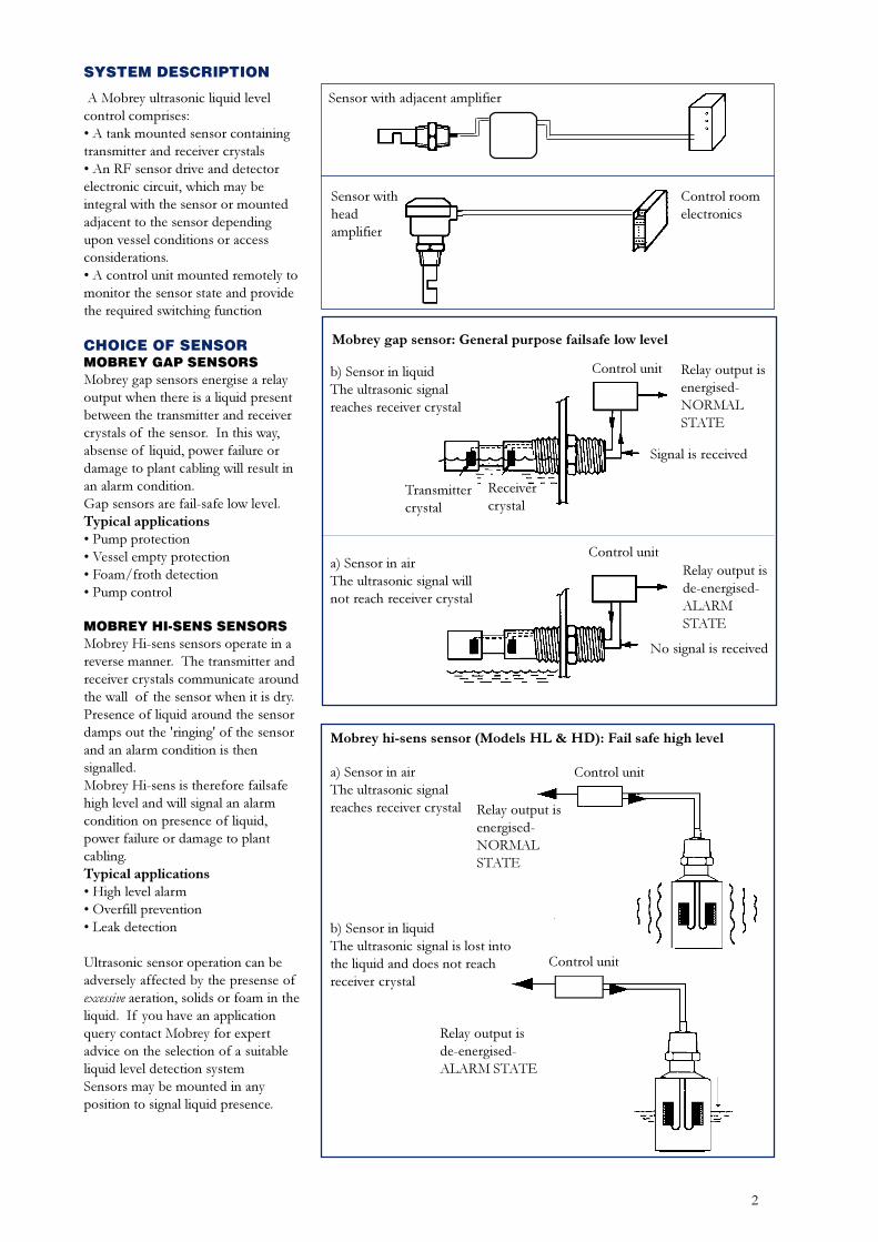
SYSTEM DESCRIPTION
A Mobrey ultrasonic liquid levelcontrol comprises:� A tank mounted sensor containingtransmitter and receiver crystals� An RF sensor drive and detectorelectronic circuit, which may beintegral with the sensor or mountedadjacent to the sensor dependingupon vessel conditions or accessconsiderations.� A control unit mounted remotely tomonitor the sensor state and providethe required switching function
CHOICE OF SENSORMOBREY GAP SENSORSMobrey gap sensors energise a relayoutput when there is a liquid presentbetween the transmitter and receivercrystals of the sensor. In this way,absense of liquid, power failure ordamage to plant cabling will result inan alarm condition.Gap sensors are fail-safe low level.Typical applications� Pump protection� Vessel empty protection� Foam/froth detection� Pump control
MOBREY HI-SENS SENSORSMobrey Hi-sens sensors operate in areverse manner. The transmitter andreceiver crystals communicate aroundthe wall of the sensor when it is dry.Presence of liquid around the sensordamps out the 'ringing' of the sensorand an alarm condition is thensignalled.Mobrey Hi-sens is therefore failsafehigh level and will signal an alarmcondition on presence of liquid,power failure or damage to plantcabling.Typical applications� High level alarm� Overfill prevention� Leak detection
Ultrasonic sensor operation can beadversely affected by the presense ofexcessive aeration, solids or foam in theliquid. If you have an applicationquery contact Mobrey for expertadvice on the selection of a suitableliquid level detection systemSensors may be mounted in anyposition to signal liquid presence.
Mobrey gap sensor: General purpose failsafe low level
a) Sensor in airThe ultrasonic signal willnot reach receiver crystal
b) Sensor in liquidThe ultrasonic signalreaches receiver crystal
Control unit Relay output isenergised-NORMALSTATE
Control unitRelay output isde-energised-ALARMSTATE
Signal is received
Transmittercrystal
Receivercrystal
No signal is received
Mobrey hi-sens sensor (Models HL & HD): Fail safe high level
a) Sensor in airThe ultrasonic signalreaches receiver crystal
b) Sensor in liquidThe ultrasonic signal is lost intothe liquid and does not reachreceiver crystal
Relay output isenergised-NORMALSTATE
Control unit
Control unit
Relay output isde-energised-ALARM STATE
Sensor with adjacent amplifier
Sensor withheadamplifier
Control roomelectronics
3
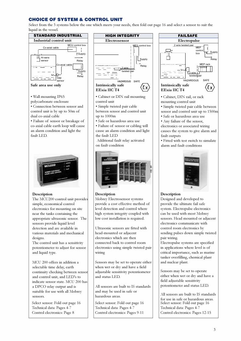
CHOICE OF SYSTEM & CONTROL UNIT
STANDARD INDUSTRIALIndustrial control unit
Safe area use only
DescriptionDesigned and developed toprovide the ultimate fail safesystem. Electropulse electronicscan be used with most Mobreysensors. Head mounted or adjacentelectronics communicate withcontrol room electronics bysending pulses down simple twistedpair wiring.Electropulse systems are specifiedin applications where level is ofcritical importance, such as marinetanker overfilling, chemical plantand nuclear plant.
Sensors may be set to operateeither when wet or dry and have afield adjustable sensitivitypotentiometer and status LED.
All sensors are built to IS standardsfor use in safe or hazardous areas.
DescriptionThe MCU200 control unit providessimple, economical controlelectronics for mounting on sitenear the tanks containing theappropriate ultrasonic sensor. Thesensors provide liquid leveldetection and are available invarious materials and mechanicaldesigns.The control unit has a sensitivitypotentiometer to adjust for sensorand liquid type.
MCU 200 offers in addition aselectable time delay, earthcontinuity checking between sensorand control unit, and LED's toindicate sensor state. MCU 200 hasa DPCO relay output and issuitable for use with all Mobreysensors.
� Wall mounting IP65polycarbonate enclosure� Connection between sensor andcontrol unit is by up to 50m ofdual co-axial cable� Failure of sensor or breakage ofco-axial cable earth loop will causean alarm condition and light thefault LED.
DescriptionMobrey Electrosensor systemsprovide a cost effective method oflevel detection and control wherehigh system integrity coupled withlow cost installation is required.
Ultrasonic sensors are fitted withhead-mounted or adjacentelectronics which are thenconnected back to control roomelectronics using simple twisted pairwiring
Sensors may be set to operate eitherwhen wet or dry and have a fieldadjustable sensitivity potentiometerand status LED.
All sensors are built to IS standardsand may be used in safe orhazardous areas.
� Cabinet or DIN rail mountingcontrol unit� Simple twisted pair cablebetween sensor and control unitup to 1000m� Safe or hazardous area use� Failure of sensor or cabling willcause an alarm condition and lightthe fault LED Additional fault relay activatedon fault condition
HIGH INTEGRITYElectrosensor
Intrinsically safeEExia IIC T4
FAILSAFEElectropulse
� Cabinet, DIN rail, or rackmounting control unit� Simple twisted pair cable betweensensor and control unit up to 1500m� Safe or hazardous area use� Any failure of the sensor,electronics or associated wiringcauses the system to give alarm andfault outputs� Fitted with test switch to simulatealarm and fault conditions
Intrinsically safeEExia IIC T4
Select sensor: Fold out page 16Technical data: Pages 4-7Control electronics: Page 8
Select sensor: Fold out page 16Technical data: Pages 4-7Control electronics: Pages 9-11
Select sensor: Fold out page 16Technical data: Pages 4-7Control electronics: Pages 12-15
Select from the 3 systems below the one which meets your needs, then fold out page 16 and select a sensor to suit theliquid in the vessel.
Supply
Relay
MES control box
SAFEHAZARDOUS
2 wiretwisted pair
MCU control box
Supply
Relay
Co-axial cable
Gapsensor
Hi-senssensor
Co-axial cable
Supply
Relay
2 wire twisted pairMEPcontrolbox Supply
Relay
MEP rackcontrol
SAFEHAZARDOUS
2 wiretwisted pair
4
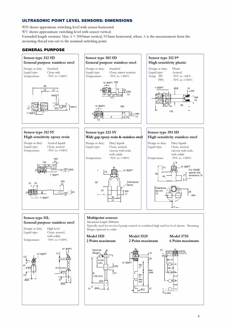
ULTRASONIC POINT LEVEL SENSORS: DIMENSIONS
WH shows approimate switching level with sensor horizontalWV shows approximate switching level with sensor verticalExtended length versions: Max A = 3000mm vertical, 915mm horizontal, where A is the measurement from themounting thread run-out to the nominal switching point.
GENERAL PURPOSE
Sensor type 332 SDGeneral purpose stainless steel
Sensor type 302 SDGeneral purpose stainless steel
Design or duty: StandardLiquid type: Clean, minor aerationTemperature: -70oC to +150oC
Design or duty: StandardLiquid type: Clean onlyTemperature: -70oC to +150oC
Sensor type 312 S*High sensitivity plastic
Design or duty: PlasticLiquid type: AeratedTemp. PP: -70oC to +65oC PPS: -70oC to +130oC
Sensor type 312 SYHigh sensitivity epoxy resin
Design or duty: Aerated liquidsLiquid type: Clean, aeratedTemperature: -70oC to +130oC
Sensor type 323 SYWide gap epoxy resin & stainless steel
Design or duty: Dirty liquidsLiquid type: Clean, aerated,
viscous with scale,with solids
Temperature: -70oC to +130oC
Sensor type 393 SDHigh sensitivity stainless steel
Design or duty: Dirty liquidsLiquid type: Clean, aerated,
viscous with scale,with solids
Temperature: -70oC to +150oC
Sensor type HLGeneral purpose stainless steel
Design or duty: High levelLiquid type: Clean, aerated,
with solidsTemperature: -70oC to +130oC
Multipoint sensorsMaximum length 3000mmTypically used for two level pump control or combined high and low level alarms. Mountingflanges optional to order
Model HD2 Point maximum
Model 352S2 Point maximum
Model 373S6 Point maximum
10
10
A (59 min)WV
Ø49
¾" BSPT
31
47
¾" BSPT
WV
Ø49
31
2510
130
25
WV20
Ø25WH19
1" BSPT
11
35 37
25
10WV20
WH19
1" BSPT 36
99
WV17
Transducerepoxy
WH
¾" BSPT18
33
51
Clearancedia min75
28
66
For 393SEspecify thisdimension 'A'
WH
¾" BSPT
13
13
27
10
40
130
10
8020
WVØ26
WH16
1" BSPT
12
117
10 20 27
WV
Ø22
A
WH13
¾" BSPT
13 24
2210
20 24
WV
WH13
¾" BSPT
13
22
85
19 37
8.5WV
Ø286 WH17
1" BSPT
1010
Optionalflange
Min 27
WV
Ø22
A (59min)
20
3731
¾" BSPT
13 WV
31
D C B A
Min 35
Min37
Min71Max455
Max3000B
(159 min)
Ø49
WV
5
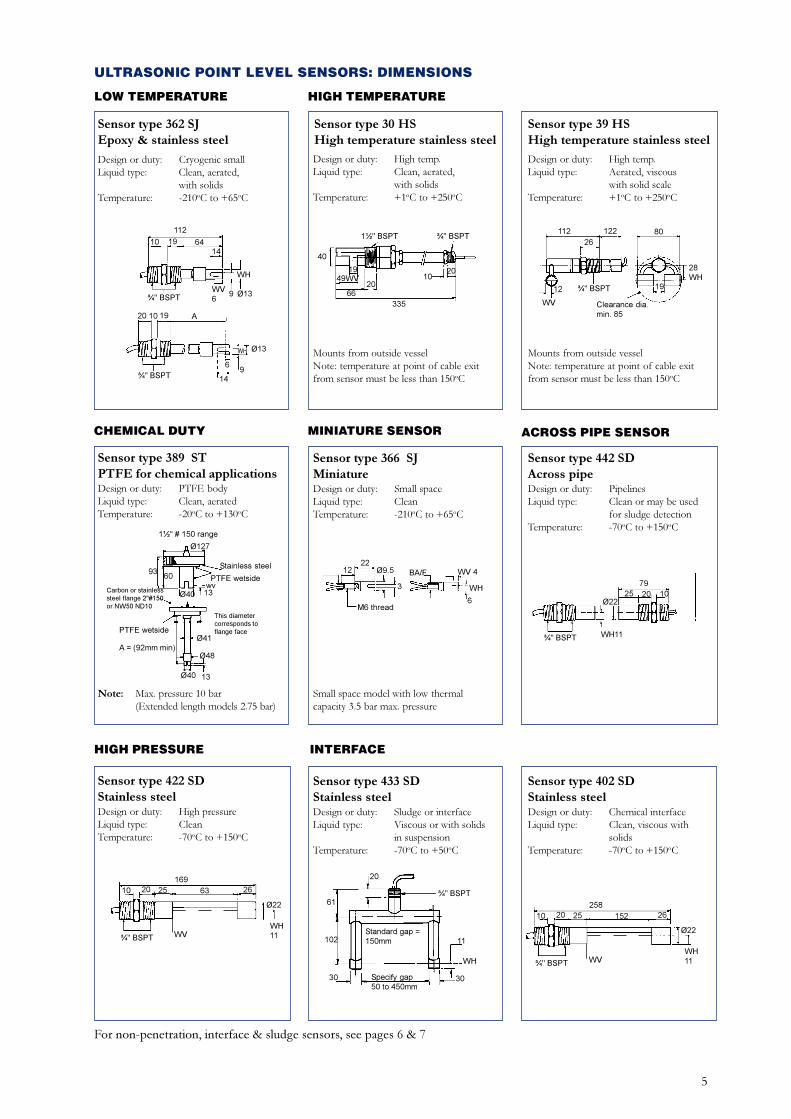
HIGH TEMPERATURELOW TEMPERATURE
CHEMICAL DUTY MINIATURE SENSOR ACROSS PIPE SENSOR
HIGH PRESSURE INTERFACE
For non-penetration, interface & sludge sensors, see pages 6 & 7
Sensor type 362 SJEpoxy & stainless steel
Design or duty: Cryogenic smallLiquid type: Clean, aerated,
with solidsTemperature: -210oC to +65oC
Sensor type 30 HSHigh temperature stainless steel
Design or duty: High temp.Liquid type: Clean, aerated,
with solidsTemperature: +1oC to +250oC
Mounts from outside vesselNote: temperature at point of cable exitfrom sensor must be less than 150oC
Sensor type 39 HSHigh temperature stainless steel
Design or duty: High temp.Liquid type: Aerated, viscous
with solid scaleTemperature: +1oC to +250oC
Mounts from outside vesselNote: temperature at point of cable exitfrom sensor must be less than 150oC
Sensor type 389 STPTFE for chemical applicationsDesign or duty: PTFE bodyLiquid type: Clean, aeratedTemperature: -20oC to +130oC
Note: Max. pressure 10 bar(Extended length models 2.75 bar)
Sensor type 366 SJMiniatureDesign or duty: Small spaceLiquid type: CleanTemperature: -210oC to +65oC
Small space model with low thermalcapacity 3.5 bar max. pressure
Sensor type 442 SDAcross pipeDesign or duty: PipelinesLiquid type: Clean or may be used
for sludge detectionTemperature: -70oC to +150oC
Sensor type 422 SDStainless steelDesign or duty: High pressureLiquid type: CleanTemperature: -70oC to +150oC
Sensor type 433 SDStainless steelDesign or duty: Sludge or interfaceLiquid type: Viscous or with solids
in suspensionTemperature: -70oC to +50oC
Sensor type 402 SDStainless steelDesign or duty: Chemical interfaceLiquid type: Clean, viscous with
solidsTemperature: -70oC to +150oC
2212 Ø9.5
3
M6 thread
BA/F WV 4
WH
6
16910 20 25 63 26
Ø22
¾" BSPT
WH11WV
25810 20 25 152 26
Ø22
¾" BSPT
WH11WV
20
61
102
30 30
11
WH
Standard gap =150mm
Specify gap50 to 450mm
¾" BSPT
7925 20 10
Ø22
¾" BSPT WH11
Carbon or stainlesssteel flange 2"#150or NW50 ND10
This diametercorresponds toflange face
1½" # 150 range
Ø127
9360
Ø40
Stainless steel
PTFE wetside
PTFE wetsideØ41
Ø48
13Ø40
A = (92mm min)
13wv
40
1½" BSPT ¾" BSPT
1949WV
6620
335
1020
10
112
WH
Ø13
19 64
¾" BSPT
14
WV6
9
20 10 19 A
¾" BSPT
WH Ø13
14
69
¾" BSPT
Clearance dia.min. 85
112 122 80
28WH
1912
WV
26
ULTRASONIC POINT LEVEL SENSORS: DIMENSIONS
6
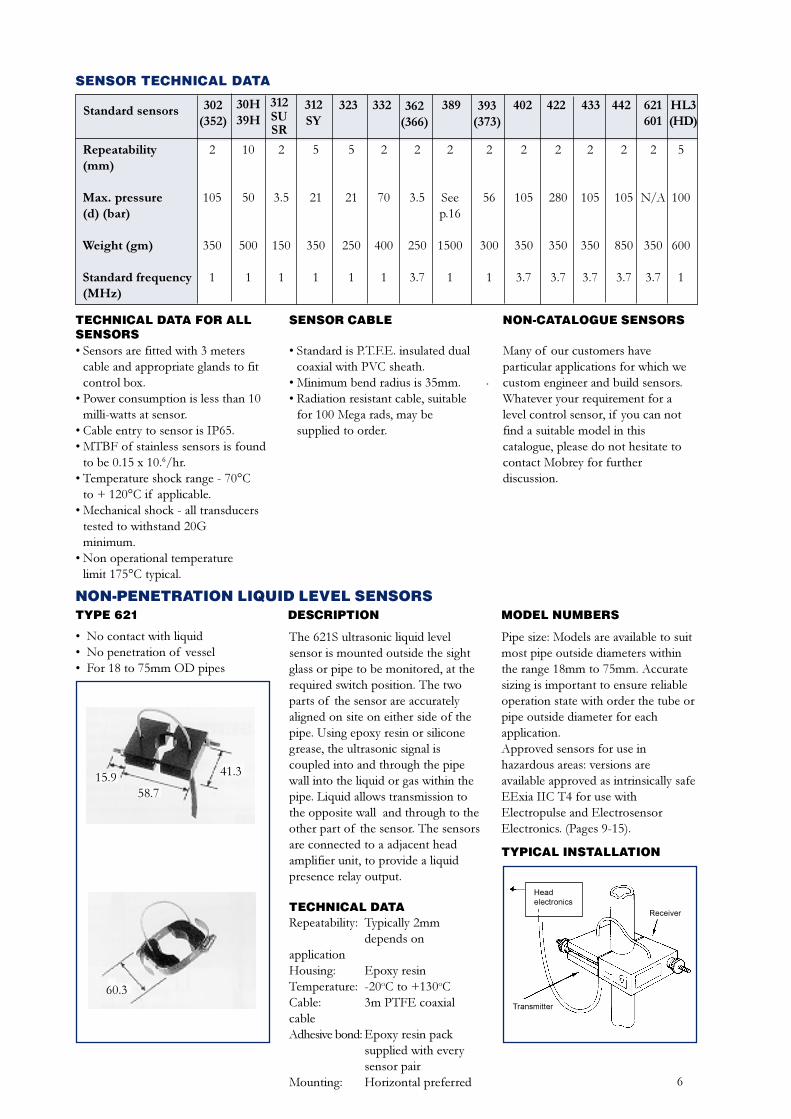
SENSOR TECHNICAL DATA
Standard sensors 30H39H
312SUSR
312SY
393(373)
302(352)
362(366)
323 332 389 402 422 433 442 621601
HL3(HD)
Repeatability(mm)
Max. pressure(d) (bar)
Weight (gm)
Standard frequency(MHz)
2
105
350
1
10
50
500
1
5
21
350
1
5
21
250
1
2
70
400
1
2
3.5
250
3.7
2
Seep.16
1500
1
2
56
300
1
2
105
350
3.7
2
280
350
3.7
2
105
350
3.7
2
105
850
3.7
2
N/A
350
3.7
5
100
600
1
2
3.5
150
1
TECHNICAL DATA FOR ALLSENSORS� Sensors are fitted with 3 meters
cable and appropriate glands to fitcontrol box.
� Power consumption is less than 10milli-watts at sensor.
� Cable entry to sensor is IP65.� MTBF of stainless sensors is found
to be 0.15 x 10.6/hr.� Temperature shock range - 70°C
to + 120°C if applicable.� Mechanical shock - all transducers
tested to withstand 20Gminimum.
� Non operational temperaturelimit 175°C typical.
SENSOR CABLE
� Standard is P.T.F.E. insulated dualcoaxial with PVC sheath.
� Minimum bend radius is 35mm.� Radiation resistant cable, suitable
for 100 Mega rads, may besupplied to order.
NON-CATALOGUE SENSORS
Many of our customers haveparticular applications for which wecustom engineer and build sensors.Whatever your requirement for alevel control sensor, if you can notfind a suitable model in thiscatalogue, please do not hesitate tocontact Mobrey for furtherdiscussion.
NON-PENETRATION LIQUID LEVEL SENSORSDESCRIPTIONTYPE 621
� No contact with liquid� No penetration of vessel� For 18 to 75mm OD pipes
The 621S ultrasonic liquid levelsensor is mounted outside the sightglass or pipe to be monitored, at therequired switch position. The twoparts of the sensor are accuratelyaligned on site on either side of thepipe. Using epoxy resin or siliconegrease, the ultrasonic signal iscoupled into and through the pipewall into the liquid or gas within thepipe. Liquid allows transmission tothe opposite wall and through to theother part of the sensor. The sensorsare connected to a adjacent headamplifier unit, to provide a liquidpresence relay output.
TECHNICAL DATARepeatability: Typically 2mm
depends onapplicationHousing: Epoxy resinTemperature: -20oC to +130oCCable: 3m PTFE coaxialcableAdhesive bond: Epoxy resin pack
supplied with everysensor pair
Mounting: Horizontal preferred
MODEL NUMBERS
Pipe size: Models are available to suitmost pipe outside diameters withinthe range 18mm to 75mm. Accuratesizing is important to ensure reliableoperation state with order the tube orpipe outside diameter for eachapplication.Approved sensors for use inhazardous areas: versions areavailable approved as intrinsically safeEExia IIC T4 for use withElectropulse and ElectrosensorElectronics. (Pages 9-15).
TYPICAL INSTALLATION
15.958.7
41.3
60.3
Headelectronics
Transmitter
Receiver
7
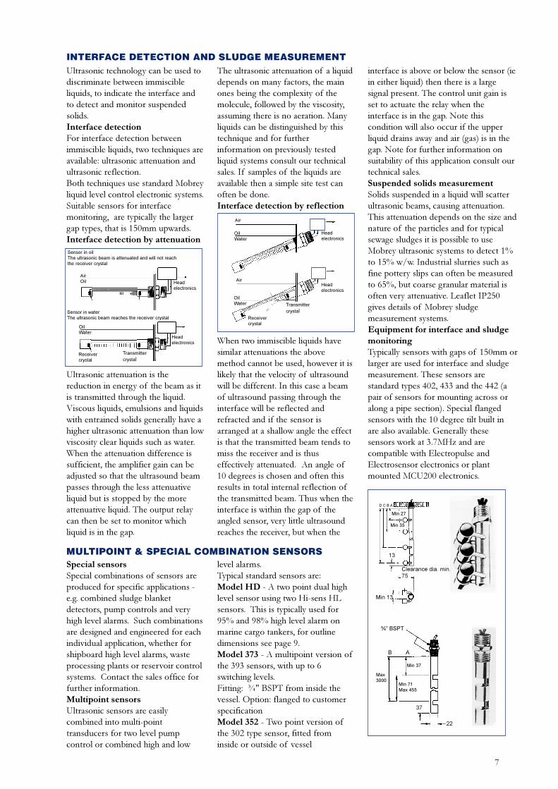
INTERFACE DETECTION AND SLUDGE MEASUREMENTUltrasonic technology can be used todiscriminate between immiscibleliquids, to indicate the interface andto detect and monitor suspendedsolids.Interface detectionFor interface detection betweenimmiscible liquids, two techniques areavailable: ultrasonic attenuation andultrasonic reflection.Both techniques use standard Mobreyliquid level control electronic systems.Suitable sensors for interfacemonitoring, are typically the largergap types, that is 150mm upwards.Interface detection by attenuation
Ultrasonic attenuation is thereduction in energy of the beam as itis transmitted through the liquid.Viscous liquids, emulsions and liquidswith entrained solids generally have ahigher ultrasonic attenuation than lowviscosity clear liquids such as water.When the attenuation difference issufficient, the amplifier gain can beadjusted so that the ultrasound beampasses through the less attenuativeliquid but is stopped by the moreattenuative liquid. The output relaycan then be set to monitor whichliquid is in the gap.
The ultrasonic attenuation of a liquiddepends on many factors, the mainones being the complexity of themolecule, followed by the viscosity,assuming there is no aeration. Manyliquids can be distinguished by thistechnique and for furtherinformation on previously testedliquid systems consult our technicalsales. If samples of the liquids areavailable then a simple site test canoften be done.Interface detection by reflection
When two immiscible liquids havesimilar attenuations the abovemethod cannot be used, however it islikely that the velocity of ultrasoundwill be different. In this case a beamof ultrasound passing through theinterface will be reflected andrefracted and if the sensor isarranged at a shallow angle the effectis that the transmitted beam tends tomiss the receiver and is thuseffectively attenuated. An angle of10 degrees is chosen and often thisresults in total internal reflection ofthe transmitted beam. Thus when theinterface is within the gap of theangled sensor, very little ultrasoundreaches the receiver, but when the
interface is above or below the sensor (iein either liquid) then there is a largesignal present. The control unit gain isset to actuate the relay when theinterface is in the gap. Note thiscondition will also occur if the upperliquid drains away and air (gas) is in thegap. Note for further information onsuitability of this application consult ourtechnical sales.Suspended solids measurementSolids suspended in a liquid will scatterultrasonic beams, causing attenuation.This attenuation depends on the size andnature of the particles and for typicalsewage sludges it is possible to useMobrey ultrasonic systems to detect 1%to 15% w/w. Industrial slurries such asfine pottery slips can often be measuredto 65%, but coarse granular material isoften very attenuative. Leaflet IP250gives details of Mobrey sludgemeasurement systems.Equipment for interface and sludgemonitoringTypically sensors with gaps of 150mm orlarger are used for interface and sludgemeasurement. These sensors arestandard types 402, 433 and the 442 (apair of sensors for mounting across oralong a pipe section). Special flangedsensors with the 10 degree tilt built inare also available. Generally thesesensors work at 3.7MHz and arecompatible with Electropulse andElectrosensor electronics or plantmounted MCU200 electronics.
MULTIPOINT & SPECIAL COMBINATION SENSORSSpecial sensorsSpecial combinations of sensors areproduced for specific applications -e.g. combined sludge blanketdetectors, pump controls and veryhigh level alarms. Such combinationsare designed and engineered for eachindividual application, whether forshipboard high level alarms, wasteprocessing plants or reservoir controlsystems. Contact the sales office forfurther information.Multipoint sensorsUltrasonic sensors are easilycombined into multi-pointtransducers for two level pumpcontrol or combined high and low
level alarms.Typical standard sensors are:Model HD - A two point dual highlevel sensor using two Hi-sens HLsensors. This is typically used for95% and 98% high level alarm onmarine cargo tankers, for outlinedimensions see page 9.Model 373 - A multipoint version ofthe 393 sensors, with up to 6switching levels.Fitting: ¾" BSPT from inside thevessel. Option: flanged to customerspecificationModel 352 - Two point version ofthe 302 type sensor, fitted frominside or outside of vessel
Headelectronics
Headelectronics
Sensor in oilThe ultrasonic beam is attenuated and will not reachthe receiver crystal
Sensor in waterThe ultrasonic beam reaches the receiver crystal
AirOil
OilWater
Receivercrystal
Transmittercrystal
Headelectronics
Headelectronics
Air
OilWater
Receivercrystal
Transmittercrystal
OilWater
Air
Min 71Max 455
37
Min 37
B A
22
Max3000
¾" BSPT
13
Min 27
Min 13
D C B A
Min 35
Clearance dia. min.75
8
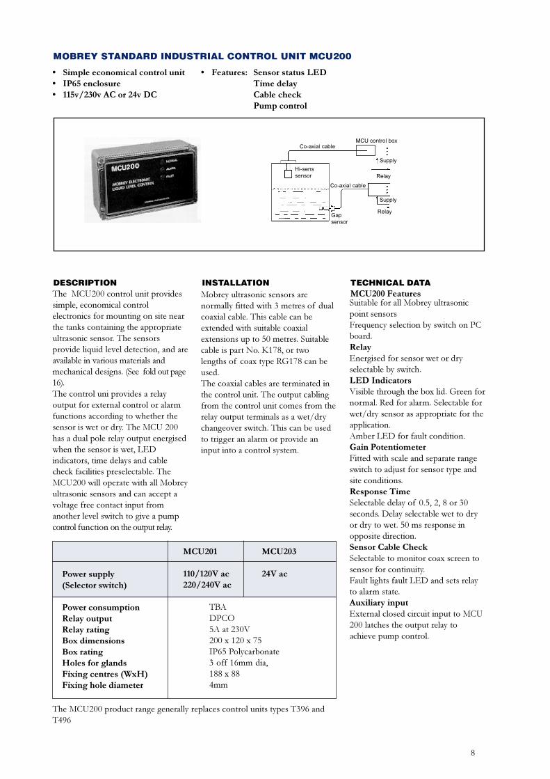
MOBREY STANDARD INDUSTRIAL CONTROL UNIT MCU200
� Simple economical control unit� IP65 enclosure� 115v/230v AC or 24v DC
DESCRIPTION INSTALLATIONThe MCU200 control unit providessimple, economical controlelectronics for mounting on site nearthe tanks containing the appropriateultrasonic sensor. The sensorsprovide liquid level detection, and areavailable in various materials andmechanical designs. (See fold out page16).The control uni provides a relayoutput for external control or alarmfunctions according to whether thesensor is wet or dry. The MCU 200has a dual pole relay output energisedwhen the sensor is wet, LEDindicators, time delays and cablecheck facilities preselectable. TheMCU200 will operate with all Mobreyultrasonic sensors and can accept avoltage free contact input fromanother level switch to give a pumpcontrol function on the output relay.
Mobrey ultrasonic sensors arenormally fitted with 3 metres of dualcoaxial cable. This cable can beextended with suitable coaxialextensions up to 50 metres. Suitablecable is part No. K178, or twolengths of coax type RG178 can beused.The coaxial cables are terminated inthe control unit. The output cablingfrom the control unit comes from therelay output terminals as a wet/drychangeover switch. This can be usedto trigger an alarm or provide aninput into a control system.
TECHNICAL DATAMCU200 FeaturesSuitable for all Mobrey ultrasonicpoint sensorsFrequency selection by switch on PCboard.RelayEnergised for sensor wet or dryselectable by switch.LED IndicatorsVisible through the box lid. Green fornormal. Red for alarm. Selectable forwet/dry sensor as appropriate for theapplication.Amber LED for fault condition.Gain PotentiometerFitted with scale and separate rangeswitch to adjust for sensor type andsite conditions.Response TimeSelectable delay of 0.5, 2, 8 or 30seconds. Delay selectable wet to dryor dry to wet. 50 ms response inopposite direction.Sensor Cable CheckSelectable to monitor coax screen tosensor for continuity.Fault lights fault LED and sets relayto alarm state.Auxiliary inputExternal closed circuit input to MCU200 latches the output relay toachieve pump control.
Power supply(Selector switch)
Power consumptionRelay outputRelay ratingBox dimensionsBox ratingHoles for glandsFixing centres (WxH)Fixing hole diameter
MCU201 MCU203
110/120V ac 24V ac220/240V ac
TBADPCO5A at 230V200 x 120 x 75IP65 Polycarbonate3 off 16mm dia,188 x 884mm
The MCU200 product range generally replaces control units types T396 andT496
� Features: Sensor status LEDTime delayCable checkPump control
MCU control box
Supply
Relay
Co-axial cable
Gapsensor
Hi-senssensor
Co-axial cable
Supply
Relay
9
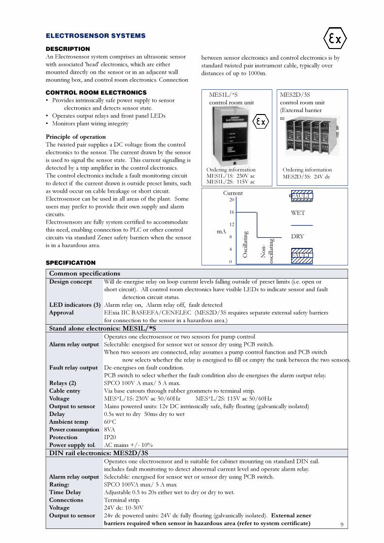
ELECTROSENSOR SYSTEMS
DESCRIPTIONAn Electrosensor system comprises an ultrasonic sensorwith associated 'head' electronics, which are eithermounted directly on the sensor or in an adjacent wallmounting box, and control room electronics. Connection
Principle of operationThe twisted pair supplies a DC voltage from the controlelectronics to the sensor. The current drawn by the sensoris used to signal the sensor state. This current signalling isdetected by a trip amplifier in the control electronics.The control electronics include a fault monitoring circuitto detect if the current drawn is outside preset limits, suchas would occur on cable breakage or short circuit.Electrosensor can be used in all areas of the plant. Someusers may prefer to provide their own supply and alarmcircuits.Electrosensors are fully system certified to accommodatethis need, enabling connection to PLC or other controlcircuits via standard Zener safety barriers when the sensoris in a hazardous area.
CONTROL ROOM ELECTRONICS� Provides intrinsically safe power supply to sensor
electronics and detects sensor state.� Operates output relays and front panel LEDs� Monitors plant wiring integrity
MES1L/*Scontrol room unit
MES2D/3Scontrol room unit(External barrierrequired)
Ordering informationMES2D/3S: 24V dc
SPECIFICATION
Common specificationsDesign concept Will de-energise relay on loop current levels falling outside of preset limits (i.e. open or
short circuit). All control room electronics have visible LEDs to indicate sensor and faultdetection circuit status.
LED indicators (3) Alarm relay on, Alarm relay off, fault detectedApproval EExia IIC BASEEFA/CENELEC (MES2D/3S requires separate external safety barriers
for connection to the sensor in a hazardous area.)Stand alone electronics: MES1L/*S
Operates one electrosensor or two sensors for pump controlAlarm relay output Selectable: energised for sensor wet or sensor dry using PCB switch.
When two sensors are connected, relay assumes a pump control function and PCB switchnow selects whether the relay is energised to fill or empty the tank between the two sensors.
Fault relay output De-energises on fault condition.PCB switch to select whether the fault condition also de-energises the alarm output relay.
Relays (2) SPCO 100V A max/ 5 A max.Cable entry Via base cutouts through rubber grommets to terminal strip.Voltage MES*L/1S: 230V ac 50/60Hz MES*L/2S: 115V ac 50/60HzOutput to sensor Mains powered units: 12v DC intrinsically safe, fully floating (galvanically isolated)Delay 0.5s wet to dry 50ms dry to wetAmbient temp 60oCPower consumption 8VAProtection IP20Power supply tol. AC mains +/- 10%DIN rail electronics: MES2D/3S
Operates one electrosensor and is suitable for cabinet mounting on standard DIN rail.includes fault monitoring to detect abnormal current level and operate alarm relay.
Alarm relay output Selectable: energised for sensor wet or sensor dry using PCB switch.Rating: SPCO 100VA max/ 5 A maxTime Delay Adjustable 0.5 to 20s either wet to dry or dry to wet.Connections Terminal strip.Voltage 24V dc: 10-30VOutput to sensor 24v dc powered units: 24V dc fully floating (galvanically isolated). External zener
barriers required when sensor in hazardous area (refer to system certificate)
between sensor electronics and control electronics is bystandard twisted pair instrument cable, typically overdistances of up to 1000m.
Ordering informationMES1L/1S: 230V acMES1L/2S: 115V ac
12345671234567123456712345671234567
1234567123456712345671234567
Current FAULT
FAULT
WET
DRYmA
20
16
12
8
4
0
Osc
illat
ing
Non
-os
cilla
ting
10
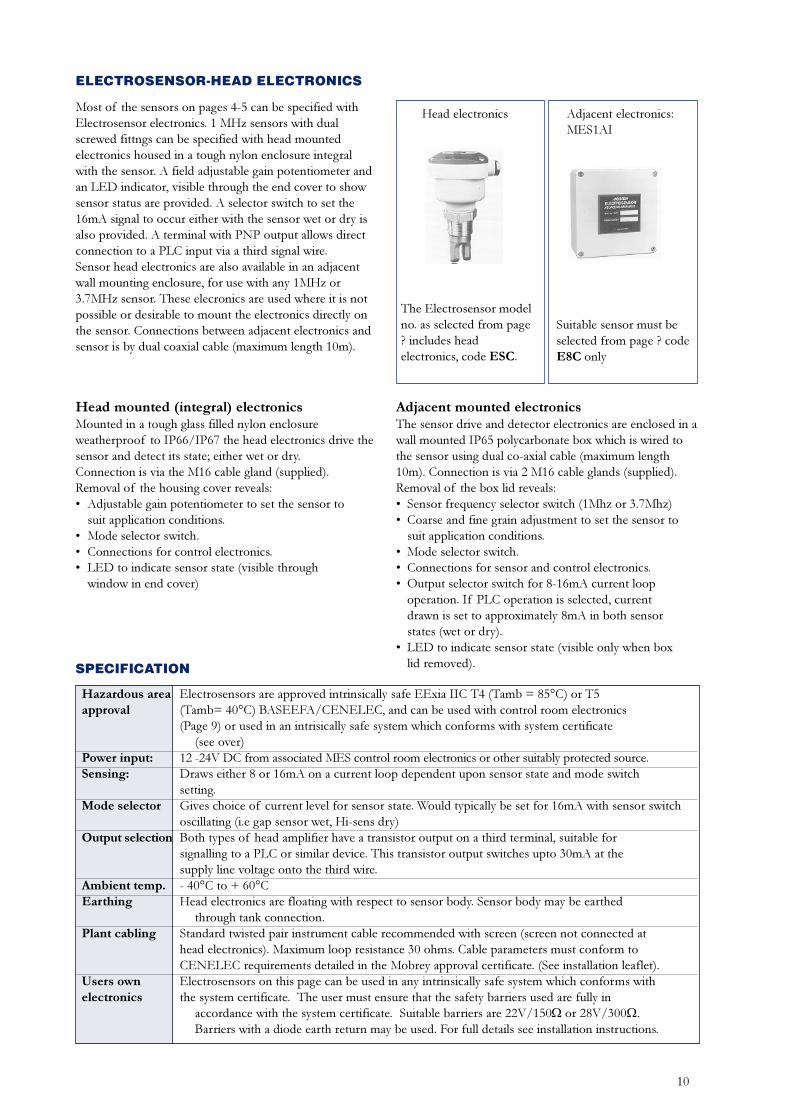
ELECTROSENSOR-HEAD ELECTRONICS
Head mounted (integral) electronicsMounted in a tough glass filled nylon enclosureweatherproof to IP66/IP67 the head electronics drive thesensor and detect its state; either wet or dry.Connection is via the M16 cable gland (supplied).Removal of the housing cover reveals:� Adjustable gain potentiometer to set the sensor to
suit application conditions.� Mode selector switch.� Connections for control electronics.� LED to indicate sensor state (visible through
window in end cover)
Hazardous area Electrosensors are approved intrinsically safe EExia IIC T4 (Tamb = 85°C) or T5approval (Tamb= 40°C) BASEEFA/CENELEC, and can be used with control room electronics
(Page 9) or used in an intrisically safe system which conforms with system certificate(see over)
Power input: 12 -24V DC from associated MES control room electronics or other suitably protected source.Sensing: Draws either 8 or 16mA on a current loop dependent upon sensor state and mode switch
setting.Mode selector Gives choice of current level for sensor state. Would typically be set for 16mA with sensor switch
oscillating (i.e gap sensor wet, Hi-sens dry)Output selection Both types of head amplifier have a transistor output on a third terminal, suitable for
signalling to a PLC or similar device. This transistor output switches upto 30mA at thesupply line voltage onto the third wire.
Ambient temp. - 40°C to + 60°CEarthing Head electronics are floating with respect to sensor body. Sensor body may be earthed
through tank connection.Plant cabling Standard twisted pair instrument cable recommended with screen (screen not connected at
head electronics). Maximum loop resistance 30 ohms. Cable parameters must conform toCENELEC requirements detailed in the Mobrey approval certificate. (See installation leaflet).
Users own Electrosensors on this page can be used in any intrinsically safe system which conforms withelectronics the system certificate. The user must ensure that the safety barriers used are fully in
accordance with the system certificate. Suitable barriers are 22V/150W or 28V/300W.Barriers with a diode earth return may be used. For full details see installation instructions.
SPECIFICATION
Most of the sensors on pages 4-5 can be specified withElectrosensor electronics. 1 MHz sensors with dualscrewed fittngs can be specified with head mountedelectronics housed in a tough nylon enclosure integralwith the sensor. A field adjustable gain potentiometer andan LED indicator, visible through the end cover to showsensor status are provided. A selector switch to set the16mA signal to occur either with the sensor wet or dry isalso provided. A terminal with PNP output allows directconnection to a PLC input via a third signal wire.Sensor head electronics are also available in an adjacentwall mounting enclosure, for use with any 1MHz or3.7MHz sensor. These elecronics are used where it is notpossible or desirable to mount the electronics directly onthe sensor. Connections between adjacent electronics andsensor is by dual coaxial cable (maximum length 10m).
The Electrosensor modelno. as selected from page? includes headelectronics, code ESC.
Head electronics Adjacent electronics:MES1AI
Suitable sensor must beselected from page ? codeE8C only
Adjacent mounted electronicsThe sensor drive and detector electronics are enclosed in awall mounted IP65 polycarbonate box which is wired tothe sensor using dual co-axial cable (maximum length10m). Connection is via 2 M16 cable glands (supplied).Removal of the box lid reveals:� Sensor frequency selector switch (1Mhz or 3.7Mhz)� Coarse and fine grain adjustment to set the sensor to
suit application conditions.� Mode selector switch.� Connections for sensor and control electronics.� Output selector switch for 8-16mA current loop
operation. If PLC operation is selected, currentdrawn is set to approximately 8mA in both sensorstates (wet or dry).
� LED to indicate sensor state (visible only when boxlid removed).
11
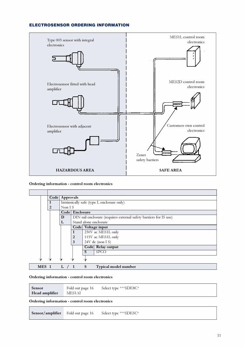
MES Mobrey ElectrosensorCode Approvals1 Intrinsically safe (type L enclosure only)2 Non I S
Code EnclosureD DIN rail enclosure (requires external safety barriers for IS use)L Stand alone enclosure
Code Voltage input1 230V ac MES1L only2 115V ac MES1L only3 24V dc (non I S)
Code Relay outputS SPCO
MES 1 L / 1 S Typical model number
Ordering information - control room electronics
ÚÚ Ú ÚÚ
ELECTROSENSOR ORDERING INFORMATION
Type 003 sensor with integralelectronics
Electrosensor fitted with headamplifier
Electrosensor with adjacentamplifier
MES1L control roomelectronics
MES2D control roomelectronics
Customers own controlelectronics
Zenersafety barriers
HAZARDOUS AREA SAFE AREA
Sensor Fold out page 16 Select type ***SDE8C*Head amplifier MES1AI
Sensor/amplifier Fold out page 16 Select type ***SDESC*
Ordering information - control room electronics
Ordering information - control room electronics
12
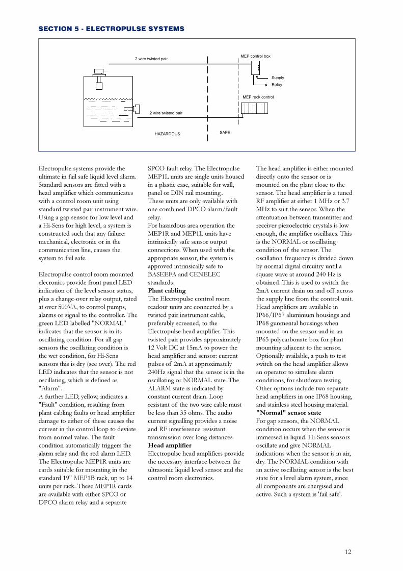
SECTION 5 - ELECTROPULSE SYSTEMS
Electropulse systems provide theultimate in fail safe liquid level alarm.Standard sensors are fitted with ahead amplifier which communicateswith a control room unit usingstandard twisted pair instrument wire.Using a gap sensor for low level anda Hi-Sens for high level, a system isconstructed such that any failure:mechanical, electronic or in thecommunication line, causes thesystem to fail safe.
Electropulse control room mountedelecronics provide front panel LEDindication of the level sensor status,plus a change-over relay output, ratedat over 500VA, to control pumps,alarms or signal to the controller. Thegreen LED labelled "NORMAL"indicates that the sensor is in itsoscillating condition. For all gapsensors the oscillating condition isthe wet condition, for Hi-Senssensors this is dry (see over). The redLED indicates that the sensor is notoscillating, which is defined as"Alarm".A further LED, yellow, indicates a"Fault" condition, resulting fromplant cabling faults or head amplifierdamage to either of these causes thecurrent in the control loop to deviatefrom normal value. The faultcondition automatically triggers thealarm relay and the red alarm LED.The Electropulse MEP1R units arecards suitable for mounting in thestandard 19" MEP1B rack, up to 14units per rack. These MEP1R cardsare available with either SPCO orDPCO alarm relay and a separate
SPCO fault relay. The ElectropulseMEP1L units are single units housedin a plastic case, suitable for wall,panel or DIN rail mounting..These units are only available withone combined DPCO alarm/faultrelay.For hazardous area operation theMEP1R and MEP1L units haveintrinsically safe sensor outputconnections. When used with theappropriate sensor, the system isapproved intrinsically safe toBASEEFA and CENELECstandards.Plant cablingThe Electropulse control roomreadout units are connected by atwisted pair instrument cable,preferably screened, to theElectropulse head amplifier. Thistwisted pair provides approximately12 Volt DC at 15mA to power thehead amplifier and sensor: currentpulses of 2mA at approximately240Hz signal that the sensor is in theoscillating or NORMAL state. TheALARM state is indicated byconstant current drain. Loopresistant of the two wire cable mustbe less than 35 ohms. The audiocurrent signalling provides a noiseand RF interference resisitanttransmission over long distances.Head amplifierElectropulse head amplifiers providethe necessary interface between theultrasonic liquid level sensor and thecontrol room electronics.
The head amplifier is either mounteddirectly onto the sensor or ismounted on the plant close to thesensor. The head amplifier is a tunedRF amplifier at either 1 MHz or 3.7MHz to suit the sensor. When theattentuation between transmitter andreceiver piezoelectric crystals is lowenough, the amplifier oscillates. Thisis the NORMAL or oscillatingcondition of the sensor. Theoscillation frequency is divided downby normal digital circuitry until asquare wave at around 240 Hz isobtained. This is used to switch the2mA current drain on and off acrossthe supply line from the control unit.Head amplifiers are available inIP66/IP67 aluminium housings andIP68 gunmental housings whenmounted on the sensor and in anIP65 polycarbonate box for plantmounting adjacent to the sensor.Optionally available, a push to testswitch on the head amplifier allowsan operator to simulate alarmconditions, for shutdown testing.Other options include two separatehead amplifiers in one IP68 housing,and stainless steel housing material."Normal" sensor stateFor gap sensors, the NORMALcondition occurs when the sensor isimmersed in liquid. Hi-Sens sensorsoscillate and give NORMALindications when the sensor is in air,dry. The NORMAL condition withan active oscillating sensor is the beststate for a level alarm system, sinceall components are energised andactive. Such a system is 'fail safe'.
2 wire twisted pairMEP control box
Supply
Relay
MEP rack control
SAFEHAZARDOUS
2 wire twisted pair
13
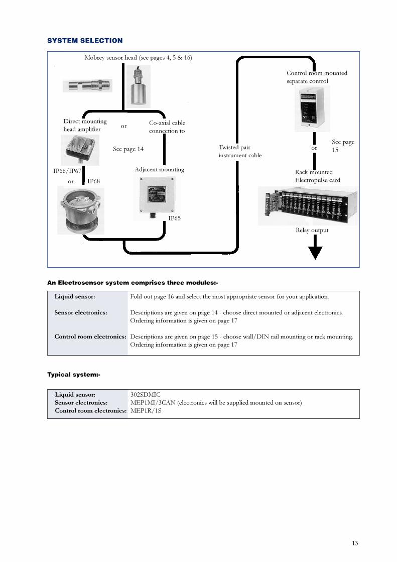
SYSTEM SELECTION
Mobrey sensor head (see pages 4, 5 & 16)
Direct mountinghead amplifier or Co-axial cable
connection to
See page 14
IP66/IP67
or IP68
Twisted pairinstrument cable
Control room mountedseparate control
orSee page15
Rack mountedElectropulse card
Relay output
Adjacent mounting
IP65
An Electrosensor system comprises three modules:-
Liquid sensor: Fold out page 16 and select the most appropriate sensor for your application.
Sensor electronics: Descriptions are given on page 14 - choose direct mounted or adjacent electronics.Ordering information is given on page 17
Control room electronics: Descriptions are given on page 15 - choose wall/DIN rail mounting or rack mounting.Ordering information is given on page 17
Typical system:-
Liquid sensor: 302SDMICSensor electronics: MEP1MI/3CAN (electronics will be supplied mounted on sensor)Control room electronics: MEP1R/1S
14
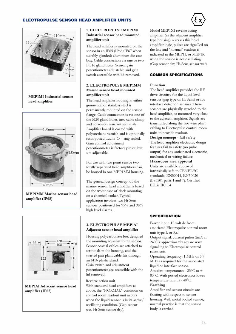
ELECTROPULSE SENSOR HEAD AMPLIFIER UNITS
1. ELECTROPULSE MEP1MIIndustrial sensor head mountedamplifier unit
The head amlifier is mounted on thesensor in an IP65 (IP66/IP67 whensuitably glanded) aluminium die castbox. Cable connection via one or twoPG16 gland holes. Sensor gainpotentiometer adjustable and gainswitch accessible with lid removed.
2. ELECTROPULSE MEP1MMMarine sensor head mountedamplifier unit
The head amplifier housing in eithergunmental or stainless steel ispermanently mounted on the sensorflange. Cable connection is via one ofthe M20 gland holes, into cable clampand corrosion resistant terminals.Amplifier board is coated withpolyurethane varnish and is optionallyresin potted. Lid is 'O' - ring sealed.Gain control adjustmentpotentionmeter is factory preset, butsite adjustable.
For use with two point sensor twototally separated head amplifiers canbe housed in one MEP1MM housing.
The general design concept of themarine sensor head amplifier is basedon the worst case of deck mountingon a chemical tanker. Typicalapplication involves two Hi-Senssensors positioned for 95% and 98%high level alarms.
3. ELECTROPULSE MEP1AIAdjacent sensor head amplifier
Housing polycarbonate box designedfor mounting adjacent to the sensor.Sensor coaxial cables are attached toterminals in the housing, and thetwisted pair plant cable fits throughan M16 plastic gland.Gain switch and adjustmentpotentiometer are accessible with thelid removed.
Reverse action unitWith standard head amplifiers asabove, the "NORMAL" condition oncontrol room readout unit occurswhen the liquid sensor is in its active/oscillating condition. (Gap sensorwet, Hi-Sens sensor dry).
Model MEP1XI reverse actingamplifier (in the adjacent amplifiertype housing) reverses this headamplifier logic, pulses are signalled onthe line and "normal" readout isindicated in the MEP1L or MEP1Rwhen the sensor is not oscillating(Gap sensor dry, Hi-Sens sensor wet).
COMMON SPECIFICATIONS
FunctionThe head amplifier provides the RFdrive circuitry for the liquid levelsensors (gap type or Hi-Sens) or forinterface detection sensors. Thesesensors are physically attached to thehead amplifier, or mounted very closeto the adjacent amplifier. Signals aretransmitted along the two wire plantcabling to Electropulse control roomunits to provide readout.Design concept - fail safetyThe head amplifier electronic designfeatures fail to safety (no pulseoutput) for any anticipated electronic,mechanical or wiring failure.Hazardous area approvalUnits are available approvedintrinsically safe to CENELECstandards, EN50014, EN50020(BS5501 parts 1 and 7). CertifiedEExia IIC T4.
SPECIFICATION
Power input: 12 volt dc fromassociated Electropulse control roomunit (type L or R).Output signal: current pulses 2mA at240Hz approximately square wavesignalling to Electropulse controlroom unit.Operating frequency: 1 MHz or 3.7MHz as required for the associatedliquid or interface sensor.Ambient temperature: - 25°C to +85°C. With potted electronics lowertemperature limit is - 40°C.EarthingAmplifier and sensor circuits arefloating with respect to sensorhousing. With metal bodied sensor,normal practice is that the sensorbody is earthed.
MEP1MI Industrial sensorhead amplifier
110mm
110mm
60mm
MEP1MM Marine sensor headamplifier (IP68)
150mm
150mm
140mm
MEP1AI Adjacent sensor headamplifier (IP65)
55 120108 6
110122
15
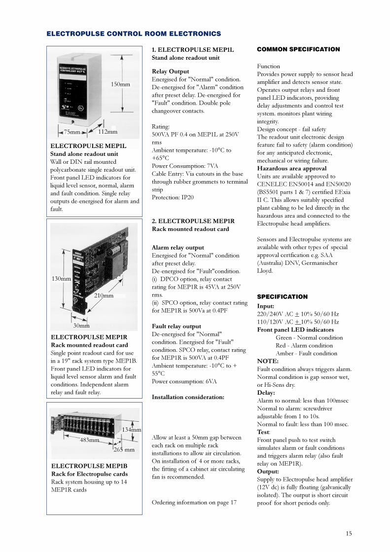
ELECTROPULSE CONTROL ROOM ELECTRONICS
1. ELECTROPULSE MEP1LStand alone readout unit
Relay OutputEnergised for "Normal" condition.De-energised for "Alarm" conditionafter preset delay. De-energised for"Fault" condition. Double polechangeover contacts.
Rating:500VA PF 0.4 on MEP1L at 250VrmsAmbient temperature: -10°C to+65°CPower Consumption: 7VACable Entry: Via cutouts in the basethrough rubber grommets to terminalstripProtection: IP20
2. ELECTROPULSE MEP1RRack mounted readout card
Alarm relay outputEnergised for "Normal" conditionafter preset delay.De-energised for "Fault"condition.(i) DPCO option, relay contactrating for MEP1R is 45VA at 250Vrms.(ii) SPCO option, relay contact ratingfor MEP1R is 500Va at 0.4PF
Fault relay outputDe-energised for "Normal"condition. Energised for "Fault"condition. SPCO relay, contact ratingfor MEP1R is 500VA at 0.4PFAmbient temperature: -10°C to +55°CPower consumption: 6VA
Installation consideration:
Allow at least a 50mm gap betweeneach rack on multiple rackinstallations to allow air circulation.On installation of 4 or more racks,the fitting of a cabinet air circulatingfan is recommended.
COMMON SPECIFICATION
FunctionProvides power supply to sensor headamplifier and detects sensor state.Operates output relays and frontpanel LED indicators, providingdelay adjustments and control testsystem. monitors plant wiringintegrity.Design concept - fail safetyThe readout unit electronic designfeature fail to safety (alarm condition)for any anticipated electronic,mechanical or wiring failure.Hazardous area approvalUnits are available approved toCENELEC EN50014 and EN50020(BS5501 parts 1 & 7) certified EExiaII C. This allows suitably specifiedplant cabling to be led directly in thehazardous area and connected to theElectropulse head amplifiers.
Sensors and Electropulse systems areavailable with other types of specialapproval certfication e.g. SAA(Australia) DNV, GermanischerLloyd.
SPECIFICATION
Input:220/240V AC + 10% 50/60 Hz110/120V AC + 10% 50/60 HzFront panel LED indicators
Green - Normal conditionRed - Alarm conditionAmber - Fault condition
NOTE:Fault condition always triggers alarm.Normal condition is gap sensor wet,or Hi-Sens dry.Delay:Alarm to normal: less than 100msecNormal to alarm: screwdriveradjustable from 1 to 10s.Normal to fault: less than 100 msec.Test:Front panel push to test switchsimulates alarm or fault conditionsand triggers alarm relay (also faultrelay on MEP1R).Output:Supply to Electropulse head amplifier(12V dc) is fully floating (galvanicallyisolated). The output is short circuitproof for short periods only.Ordering information on page 17
ELECTROPULSE MEP1LStand alone readout unitWall or DIN rail mountedpolycarbonate single readout unit.Front panel LED indicators forliquid level sensor, normal, alarmand fault condition. Single relayoutputs de-energised for alarm andfault.
150mm
75mm 112mm
ELECTROPULSE MEP1RRack mounted readout cardSingle point readout card for usein a 19" rack system type MEP1B.Front panel LED indicators forliquid level sensor alarm and faultconditions. Independent alarmrelay and fault relay.
130mm
210mm
30mm
ELECTROPULSE MEP1BRack for Electropulse cardsRack system housing up to 14MEP1R cards
483mm
134mm
265 mm
16
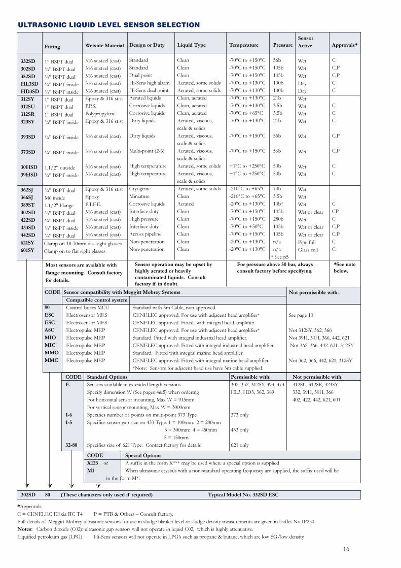
Fitting
1� BSPT dual¾� BSPT dual¾� BSPT dual¾� BSPT inside¾� BSPT inside1� BSPT dual1� BSPT dual1� BSPT dual¾� BSPT inside
¾� BSPT inside
¾� BSPT inside
1.1/2� outside¾� BSPT inside
¾� BSPT dualM6 inside1.1/2" Flange¾� BSPT dual¾� BSPT dual¾� BSPT inside¾� BSPT dual
Wetside Material
316 st.steel (cast)316 st.steel (cast)316 st.steel (cast)316 st.steel (cast)316 st.steel (cast)Epoxy & 316 st.stP.P.S.PolypropyleneEpoxy & 316 st.st
316 st.steel (cast)
316 st.steel (cast)
316 st.steel (cast)316 st.steel (cast)
Epoxy & 316 st.stEpoxyP.T.F.E.316 st.steel (cast)316 st.steel (cast)316 st.steel (cast)316 st.steel (cast)
Design or Duty
StandardStandardDual pointHi-Sens high alarmHi-Sens dual pointAerated liquidsCorrosive liquidsCorrosive liquidsDirty liquids
Dirty liquids
Multi-point (2-6)
High temperatureHigh temperature
CryogenicMiniatureCorrosive liquidsInterface dutyHigh pressureInterface dutyAcross pipelineNon-penetrationNon-penetration
332SD
302SD
352SD
HL3SD
HD3SD
312SY
312SU
312SR
323SY
393SD
373SD
30HSD
39HSD
362SJ
366SJ
389ST
402SD
422SD
433SD
442SD
621SY
601SY
Liquid Type
CleanCleanCleanAerated, some solidsAerated, some solidsClean, aeratedClean, aeratedClean, aeratedAerated, viscous,scale & solidsAerated, viscous,scale & solidsAerated, viscous,scale & solidsAerated, some solidsAerated, viscous,scale & solidsAerated, some solidsCleanAeratedCleanCleanCleanCleanCleanClean
Temperature
-70°C to +150°C-70°C to +150°C-70°C to +150°C-70°C to +130°C-70°C to +130°C-70°C to +130°C-70°C to +130°C-70°C to +65°C-70°C to +130°C
-70°C to +150°C
-70°C to +150°C
+1°C to +250°C+1°C to +250°C
-210°C to +65°C-210°C to +65°C-20°C to +130°C-70°C to +150°C-70°C to +150°C-70°C to +50°C-70°C to +150°C-20°C to +130°C-20°C to +130°C
Pressure
56b105b105b100b100b21b3.5b3.5b21b
56b
56b
50b50b
70b3.5b10b*105b280b105b105bn/an/a
Sensor
Active
WetWetWetDryDryWetWetWetWet
Wet
Wet
WetWet
WetWetWetWet or clearWetWet or clearWet or clearPipe fullGlass full
Approvals*
CC,PC,PCC
CCC
C,P
C,P
CC
CCPCC,PC,PCC
* See p5
Clamp on 18-70mm dia. sight glassesClamp on to flat sight glasses
For pressure above 50 bar, alwaysconsult factory before specifying.
Most sensors are available with
flange mounting. Consult factory
for details.
Sensor operation may be upset byhighly aerated or heavilycontaminated liquids. Consultfactory if in doubt.
*See notebelow.
CODE
80
E8C
ESC
A8C
MIO
MIC
MMO
MMC
Compatible control system
Control boxes MCUElectrosensor MESElectrosensor MESElectropulse MEPElectropulse MEPElectropulse MEPElectropulse MEPElectropulse MEP
Standard with 3m Cable, non approved.CENELEC approved. For use with adjacent head amplifier*CENELEC approved. Fitted with integral head amplifier.CENELEC approved. For use with adjacent head amplifier*Standard. Fitted with integral industrial head amplifier.CENELEC approved. Fitted with integral industrial head amplifier.Standard. Fitted with integral marine head amplifierCENELEC approved. Fitted with integral marine head amplifier.*Note: Sensors for adjacent head use have 3m cable supplied.
Not permissible with:
See page 10
Not 312SY, 362, 366Not 39H, 30H, 366, 442, 621 Not 362. 366. 442. 621. 312SY
Not 362, 366, 442, 621, 312SY
Sensor compatibility with Meggitt Mobrey Systems
CODE
E
1-6
1-5
32-80
Standard Options
Sensors available in extended length versionsSpecify dimension �A� (See pages 4&5) when orderingFor horizontal sensor mounting, Max �A� = 915mmFor vertical sensor mounting, Max �A� = 3000mmSpecifies number of points on multi-point 373 TypeSpecifies sensor gap size on 433 Type: 1 = 100mm: 2 = 200mm 3 = 300mm: 4 = 450mm 5 = 150mmSpecifies size of 621 Type: Contact factory for details
Permissible with:
302, 352, 312SY, 393, 373HL3, HD3, 362, 389
373 only
433 only
621 only
Not permissible with:
312SU, 312SR, 323SY332, 39H, 30H, 366402, 422, 442, 621, 601
CODE Special Options
X123 or A suffix in the form X*** may be used where a special option is suppliedM1 When ultrasonic crystals with a non-standard operating frequency are supplied, the suffix used will be
in the form M*.
302SD 80 (These characters only used if required) Typical Model No. 332SD ESC
ÚÚ Ú Ú
ULTRASONIC LIQUID LEVEL SENSOR SELECTION
*Approvals:C = CENELEC EExia IIC T4 P = PTB & Others � Consult factory.Full details of Meggitt Mobrey ultrasonic sensors for use in sludge blanket level or sludge density measurements are given in leaflet No IP250Notes: Carbon dioxide (C02): ultrasonic gap sensors will not operate in liquid C02, which is highly attenuative.Liquified petroleum gas (LPG): Hi-Sens sensors will not operate in LPG�s such as propane & butane, which are low SG/low density.
17
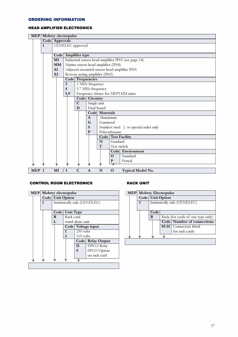
MEP Mobrey electropulseCode Approvals1 CENELEC approved
Code Amplifier typeMI Industrial sensor head amplifier IP65 (see page 14)MM Marine sensor head amplifier (IP68)AI Adjacent mounted sensor head amplifier IP65XI Reverse acting amplifier (IP65)
Code Frequencies3 1 MHz frequency4 3.7 MHz frequency5,9 Frequency choice for MEP1MM units.
Code CircuitryC Single unitD Dual board
Code MaterialsA AluminiumG GunmetalS Stainless steel } to special order onlyP Polycarbonate
Code Test FacilityN StandardT Test switch
Code EnvironmentO StandardP Potted
MEP 1 MI / 3 C A N O Typical Model No.
HEAD AMPLIFIER ELECTRONICS
MEP Mobrey ElectropulseCode Unit Option1 Intrinsically safe (CENELEC)
CodeB Rack (for cards of one type only)
Code Number of connections01-14 Connectors fitted
for rack cards
MEP 1 B / ** Typical model no.
MEP Mobrey electropulseCode Unit Option1 Intrinsically safe (CENELEC)
Code Unit TypeR Rack cardL stand alone unit
Code Voltage input1 230 volts2 115 volts
Code Relay OutputD DPCO RelayS SPCO Option
on rack card
MEP 1 R / 1 D Typical model no.
ORDERING INFORMATION
ÚÚ Ú ÚÚ Ú ÚÚ
CONTROL ROOM ELECTRONICS RACK UNIT
Ú Ú ÚÚ
ÚÚ Ú ÚÚ

18abcdef
Solartron Mobrey Limited158 Edinburgh Avenue Slough Berks England SL1 4UETel: 01753 756600 Fax: 01753 823589e-mail: [email protected] www.solartron.coma Roxboro Group Company
Bestobell Mobrey gmbh Deutschland tel: 0211/99 808-0Solartron Mobrey ltd China tel: 021 6353 5652Mobrey sp z o o Polska tel: 022 871 7865Mobrey AB Sverige tel: 08-725 01 00Mobrey SA France tel: 01.34.30.28.30Mobrey SA-NV Belgium tel: 02/465 3879Solartron Mobrey USA tel: (281) 398 7890
IP201Oct 2000
The right is reserved to amend detailsgiven in this publication without notice
Recommended