Embed Size (px)
Citation preview

Operating InstructionsIP4001, Rev CA
March 2018
Mobrey™ Series VLSVibrating Level Switch

Operating ManualIP4001, Rev CA
Mobrey Series VLSMarch 2018
Contents
Introduction . . . . . . . . . . . . . . . . . . . . . . . . . . . . . . . . . . . . . . . . . . . . . . . . . . . . . . . . . . . . . . . . . . . . . . . . . page 2Installation . . . . . . . . . . . . . . . . . . . . . . . . . . . . . . . . . . . . . . . . . . . . . . . . . . . . . . . . . . . . . . . . . . . . . . . . . . . page 3Adjustments . . . . . . . . . . . . . . . . . . . . . . . . . . . . . . . . . . . . . . . . . . . . . . . . . . . . . . . . . . . . . . . . . . . . . . . . . page 6Maintenance . . . . . . . . . . . . . . . . . . . . . . . . . . . . . . . . . . . . . . . . . . . . . . . . . . . . . . . . . . . . . . . . . . . . . . . . . page 8Specifications . . . . . . . . . . . . . . . . . . . . . . . . . . . . . . . . . . . . . . . . . . . . . . . . . . . . . . . . . . . . . . . . . . . . . . . . page 8
1.0 Introduction
1.1 Overview
Mobrey vibrating rod level switches are suitable for low and high level indication of granules and powders with a minimum 0.05 kg/dm3 density such as cement, lime, sand, grain, feed, sugar, etc. Dust Ex versions are available for using the instrument in an explosion-proof environment.
The vibrating rod is a mechanical resonant system, excited and kept in resonance by an electronic unit. The medium to be measured, when reaching the vibration rod end, will damp the vibration. The change in vibration intensity is sensed by an electronic unit, which, upon the elapse of the delay time, actuates the output circuit.
1.2 Accessories User manual (IP4001)
2 off 3-pole terminal blocks
1½-in, sealing, for BSP only
2 off M20x1.5 cable glands
1.3 Order codeK Standard model with 1 x SPDT alarm relay
H(1) High temperature model with 1 x SPDT relay (not available with Extended Cable option)
B R 1½-in. BSPT mounting
N 1½-in. NPT mounting
1 Standard length rod, 207 mm insertion length
3 Extended rod, 300-3000 mm insertion length
4 Cable extended, 1000-20000 mm insertion length
3 Aluminum Alloy housing, powder coated
9 As code 3, but with Remote Electronics
1Z 20-255 Vac / Vdc, no hazardous area approval
5A 20-250 Vac / 20-50 Vdc, ATEX Dust Certification II 1/2 D
/**** State rod or cable extension length in mm
1. Only for standard and rod extended versions.
2
Operating InstructionsIP4001, Rev CA
Mobrey Series VLSMarch 2018
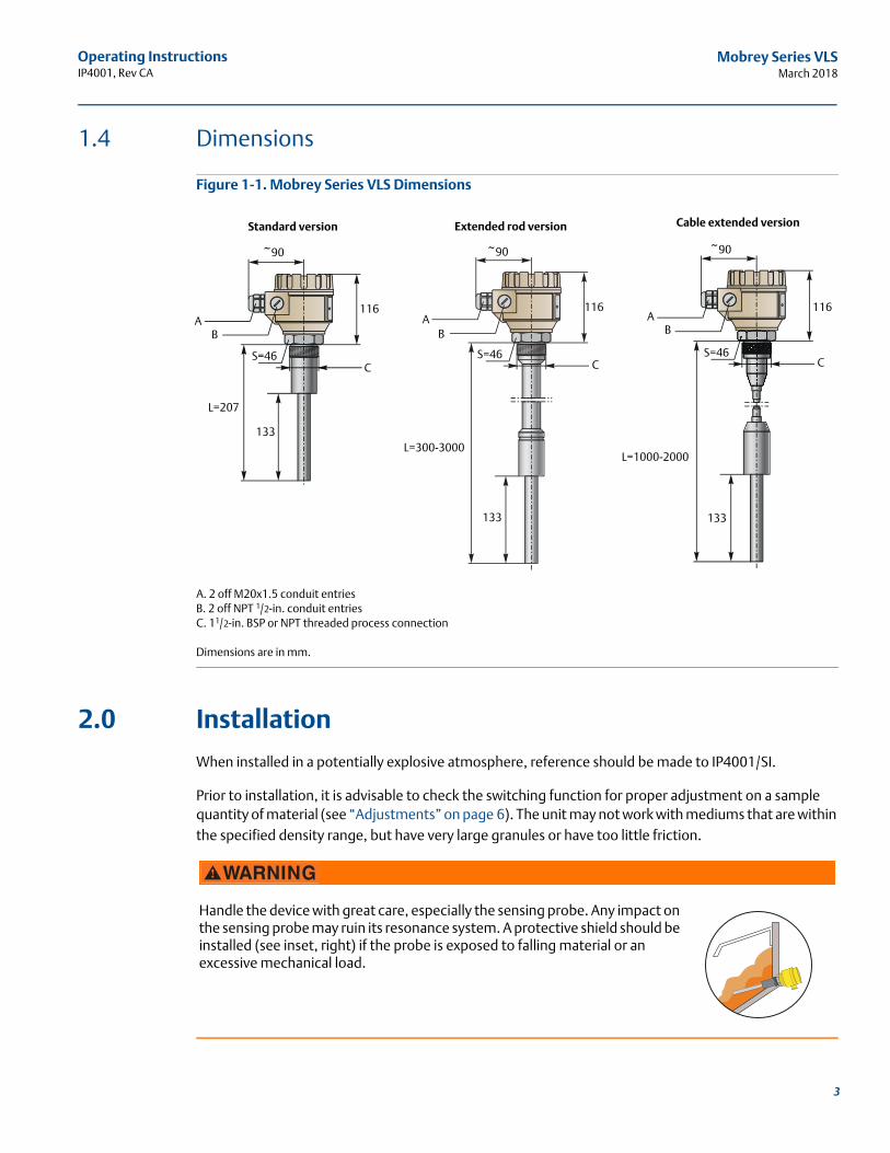
1.4 Dimensions
Figure 1-1. Mobrey Series VLS Dimensions
A. 2 off M20x1.5 conduit entriesB. 2 off NPT 1/2-in. conduit entriesC. 11/2-in. BSP or NPT threaded process connection
Dimensions are in mm.
2.0 Installation
When installed in a potentially explosive atmosphere, reference should be made to IP4001/SI.
Prior to installation, it is advisable to check the switching function for proper adjustment on a sample quantity of material (see “Adjustments” on page 6). The unit may not work with mediums that are within the specified density range, but have very large granules or have too little friction.
Handle the device with great care, especially the sensing probe. Any impact on the sensing probe may ruin its resonance system. A protective shield should be installed (see inset, right) if the probe is exposed to falling material or an excessive mechanical load.
Standard version Extended rod version Cable extended version
~90
116
L=207
133
S=46
AB
C
~90
AB
CS=46
116
133
L=300-3000 L=1000-2000
133
~90
AB
CS=46
116
3

Operating ManualIP4001, Rev CA
Mobrey Series VLSMarch 2018
Screw in the device by its hexagon neck. After screwing tight the process connection, the housing can be rotated (up to maximum of 300°), to adjust the cable gland to the required position.
It might be necessary to install the device at an offset level position relative to the switching level actually required, taking into account caving or arching of the material in the silo (see Figure 1-2).
Figure 1-2. Examples of Correct and Incorrect Installations
IncorrectCorrect
IncorrectCorrect
4

Operating InstructionsIP4001, Rev CA
Mobrey Series VLSMarch 2018
With powder level detection, the device should be installed at an inclination exceeding the angle of repose (or vertically in case of high level detection), to prevent powder deposition on the vibrating rod that might substantially reduce the self-cleaning effect. Avoid mounting the rod in a recess (Figure 1-3)
Figure 1-3. Avoid Mounting Rod in Recess
In the case of tanks that are likely to be exposed to intense vibrations, necessary provisions shall be made for damping the vibrations acting on the device (e.g. vibration damping inserts made of rubber have to be applied).
Figure 1-4. Maximum Torque and Force
Incorrect
F = 500 N.
M = 100 Nm.
M = 100 Nm.F = 45 kN.
Standard versionVLS**1
Extended rod versionVLS**3
Cable extended versionVLS**4
5

Operating ManualIP4001, Rev CA
Mobrey Series VLSMarch 2018
3.0 Adjustments
Remove the top cover of the housing to access the connection terminals and adjusting switches. In case of Dust Ex instruments, the housing cover can only be opened after the removal of the cover securing clamp.
Do not remove the wire from terminal pin 1 (Figure 1-5 on page 7) as it is an internal connection.For grounding the unit, use the PE grounding screw terminal PE.
After correct installation, the electrical connections established, the housing cover fitted and secured, the device is ready for operation. The switched-on state is indicated by the lighting of the LED.
The DENSITY setting (switch A) is to be set in accordance with the material density:
LOW position
– Recommended for loose and light materials with density below 0.1 kg/dm3.
– Represents small energy and amplitude of vibration as well as great sensitivity of detection.
HIGH position
– Recommended for (thick and heavy) materials with density over 0.1 kg/dm3.
– Represents vibration with great energy and amplitude, and small sensitivity of detection.
The instrument may not switch correctly in mediums with a density of less than 0.05 kg/dm3 or with very small internal friction.
To obtain FAIL SAFE alarm (switch C), use the de-energized state of the output as an alarm. A power breakdown will then also be considered to be an alarm (see Table 1-1 on page 7).
The delay (switch B) is to be selected to comply with requirements of the process control technology the unit is used for. Standard (switching delay is ~5 seconds) or fast response (switching delay is ~2 seconds) can be selected.
NoteWhen operating the switches, standard electrostatic discharge precautions should be taken to avoid damaging the instrument.
The enclosure must not be opened when the equipment is electrically energized.
6

Operating InstructionsIP4001, Rev CA
Mobrey Series VLSMarch 2018
Figure 1-5. Electrical Connections
Table 1-1. Operation
Power ProbeFail-safe
mode LED Relay
On
Not vibrating (covered)
LowGreen
Energized
HighRed
De-energized
Vibrating(free)
LowRed
De-energized
HighGreen
Energized
Fails Low or high
Not lit
De-energized
NO C NC
PE
N L1
PE
N L11 2 3 4 5 6
250VAC8A/AC1
A B CStatus LE D
7

Operating ManualIP4001, Rev CA
Mobrey Series VLSMarch 2018
4.0 Maintenance
Mobrey Series VLS devices do not require maintenance on a regular basis. In some instances, however, the vibrating section may need a cleaning from deposited material. This must be carried out gently, without harming the vibrating section of the vibrating rod.
Repairs during or after the guarantee period are affected by Emerson. Equipment sent back for repairs must always be cleaned or neutralized (disinfected) by the user.
5.0 Specifications
Table 1-2. Specifications for Standard, Rod Extended, and Cable Extended Versions
Category Standard Rod extended Cable extended
Probe length 207 mm 0.3 to 3 m 1 to 20 m
Wetted-parts materials1.4571 Probe: 1.4571
Cable: PE coated
Housing material Aluminum: Powder paint coated
Process connection 1½-in. BSP or 1½-in. NPT
Operating temperature ranges See Figure 1-6 and Table 1-3
Maximum pressure (absolute) 25 bar (2.5 MPa) 6 bar (0.6 MPa)
Minimum medium density(1)
1. May depend on friction and granular size of the medium.
0.05 kg/dm (maximum granular size: 10 mm)
Response time (selectable)Not vibrating (covered): < 1.8 seconds or 5±1.5 seconds
Vibrating (free): < 2 seconds or 5±1.5 seconds
Supply voltage (universal)Normal type: 20…255 Vac/Vdc
Ex type: 20…250 Vac (50/60 Hz) or 20…50 Vdc
Power consumption 2.5 VA, 2 W
Electrical connections
2 pcs. M20x1.5 cable glands with ta lIIC protection type orfor normal types M20x1.5 plastic glands for cable Ø 6 to 12 mm,
2 pcs. plug-in type terminal blocks for 0.25 to 1.5 mm2 wire cross section internal thread for 2x ½-in NPT cable protection pipe
Output SPDT (potential free), 250 Vac, 8 A, ac 1
Ingress protection IP67 (NEMA6) EN 60529:2001
Electrical protection Class I. (to be grounded)
Ex protection mark ATEX: II 1/2 D Ex ta/tb IIIC T90 °C… T170 °C Da/Db
Weight (with extension) 1.88 kg 1.88 kg (+1.4 kg/m) 1.88 kg (+ 0.6 kg/m)
Storage conditionsAmbient temperature range: -35°C to +60 °C
Relative humidity: 98% (maximum)
8

Operating InstructionsIP4001, Rev CA
Mobrey Series VLSMarch 2018
Figure 1-6. Ambient (TA) Versus Process (TP) Temperatures
Table 1-3. Thermal Data
Minimum ambient air temperature (Ta) = –30 °CMinimum process temperature (Tp) = –30 °C
VLS**435A VLSK*(1/3)35A VLSH**35A
Process temperature (Tp) (EPL Da – category 1D)
+60 °C +70 °C +80 °C...+95 °C (1)
1. The process temperature can reach +95 °C for a maximum period of one hour.
+60 °C +70 °C +95°C +110 °C +160 °C
Ambient air temperature (Ta)(EPL Db – category 2D)
+60 °C +50 °C +60 °C +60 °C +50 °C +60 °C +50 °C +35 °C
Maximum surface temperature (process connection)
+85 °C +85 °C +95 °C +85 °C +85 °C +95 °C +95 °C +135 °C
Maximum surface temperature (T)
+85 °C +85 °C +95 °C +85 °C +85 °C +95 °C +110 °C +160 °C
T Class T90°C T100°C T90°C T100°C T115°C T170°C
TA (°C)
TP (°C)
60
20
35
-30
-30
50 75 110 160
9

Operating ManualIP4001, Rev CA
Mobrey Series VLSMarch 2018
10

Operating InstructionsIP4001, Rev CA
Mobrey Series VLSMarch 2018
11

Operating InstructionsIP4001, Rev CA
March 2018
Head OfficeEmerson Automation SolutionsRosemount Measurement Ltd.158 Edinburgh AvenueSlough, Berks., SL1 4UE, UK
+44 (0)1753 756600+44 (0)1753 [email protected]
Linkedin.com/company/Emerson-Automation-Solutions
Twitter.com/Rosemount_News
Facebook.com/Rosemount
Youtube.com/user/RosemountMeasurement
Google.com/+RosemountMeasurement
Emerson Terms and Conditions of Sale are available upon requestThe Emerson logo is a trademark and service mark of Emerson Electric Co. Mobrey and Rosemount are marks of the Emerson family of companies.All other marks are the property of their respective owners.© 2018 Emerson. All rights reserved.