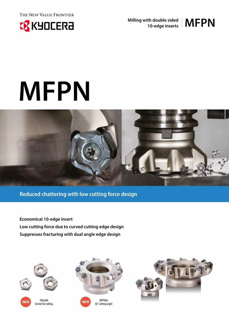
MFPNMilling with double sided10-edge inserts
Economical 10-edge insert
Low cutting force due to curved cutting edge design
Suppresses fracturing with dual angle edge design
Reduced chattering with low cutting force design
MFPN
MFPN6666° cutting angle NEWTN620M
Cermet for milling NEW
1
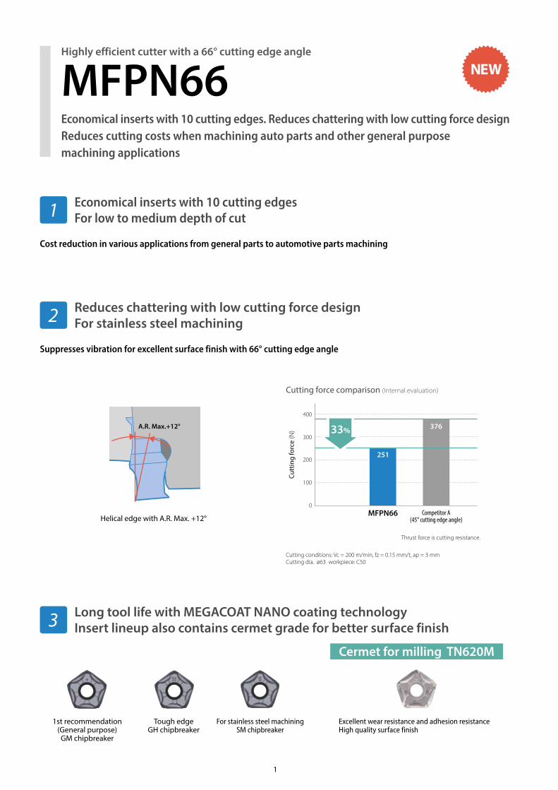
Economical inserts with 10 cutting edgesFor low to medium depth of cut
Reduces chattering with low cutting force designFor stainless steel machining
Cost reduction in various applications from general parts to automotive parts machining
Suppresses vibration for excellent surface finish with 66° cutting edge angle
Long tool life with MEGACOAT NANO coating technologyInsert lineup also contains cermet grade for better surface finish
Cutting force comparison (Internal evaluation)
Cutting conditions: Vc = 200 m/min, fz = 0.15 mm/t, ap = 3 mmCutting dia. ø63 workpiece: C50
Thrust force is cutting resistance.
Tough edgeGH chipbreaker
1st recommendation (General purpose)GM chipbreaker
For stainless steel machiningSM chipbreaker
A.R. Max.+12°
Helical edge with A.R. Max. +12°
Excellent wear resistance and adhesion resistanceHigh quality surface finish
Cermet for milling TN620M
Economical inserts with 10 cutting edges. Reduces chattering with low cutting force designReduces cutting costs when machining auto parts and other general purpose machining applications
Highly efficient cutter with a 66° cutting edge angle
MFPN66
1
2
3
Cutt
ing
forc
e (N
)
400
0
100
200
300
MFPN66 Competitor A(45° cutting edge angle)
33%
251
376
NEW
2
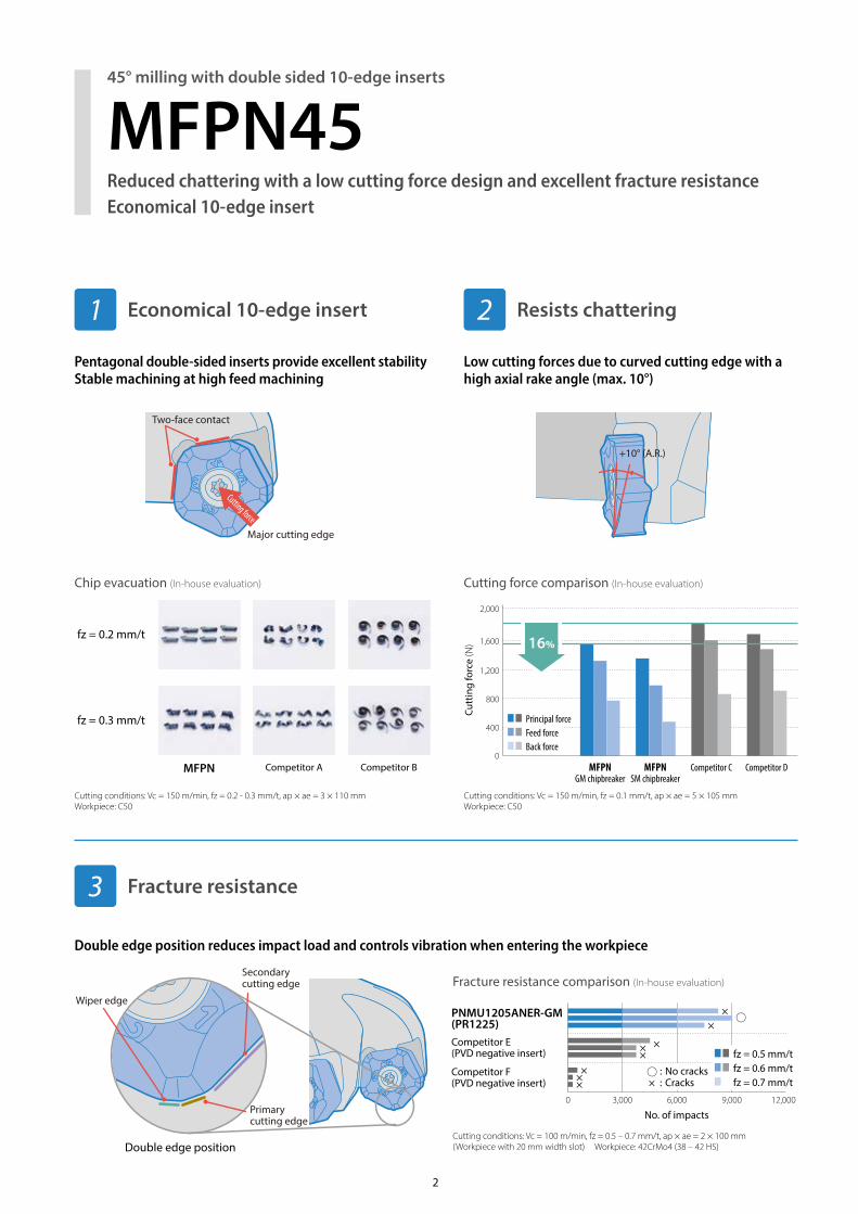
Reduced chattering with a low cutting force design and excellent fracture resistanceEconomical 10-edge insert
45° milling with double sided 10-edge inserts
Economical 10-edge insert
Pentagonal double-sided inserts provide excellent stability Stable machining at high feed machining
Low cutting forces due to curved cutting edge with a high axial rake angle (max. 10°)
Fracture resistance
Double edge position reduces impact load and controls vibration when entering the workpiece
3
1 Resists chattering2
Cutting force comparison (In-house evaluation)Chip evacuation (In-house evaluation)
Fracture resistance comparison (In-house evaluation)
MFPN45
Cutting conditions: Vc = 150 m/min, fz = 0.1 mm/t, ap × ae = 5 × 10⁵ mmWorkpiece: C50
Cutting conditions: Vc = 150 m/min, fz = 0.2 - 0.3 mm/t, ap × ae = 3 × 110 mmWorkpiece: C50
Cutting conditions: Vc = 100 m/min, fz = 0.5 – 0.7 mm/t, ap × ae = 2 × 100 mm (Workpiece with 20 mm width slot) Workpiece: 42CrMo4 (38 – 42 HS)
fz = 0.2 mm/t
fz = 0.3 mm/t
MFPN Competitor A Competitor B
Double edge position
Cutt
ing
forc
e (N
)
0
2,000
800
400
1,600
1,200
MFPNGM chipbreaker
MFPNSM chipbreaker
Competitor C Competitor D
16%
Principal forceFeed forceBack force
No. of impacts0 3,000 6,000 9,000 12,000
Competitor E(PVD negative insert)
Competitor F(PVD negative insert)
PNMU1205ANER-GM(PR1225)
××
×××
×××
fz = 0.5 mm/tfz = 0.6 mm/tfz = 0.7 mm/t
: No cracks × : Cracks
Major cutting edge
Cutting force
Two-face contact
+10° (A.R.)
Wiper edge
Primarycutting edge
Secondary cutting edge
3
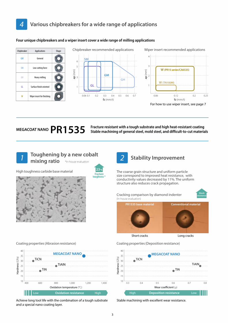
Various chipbreakers for a wide range of applications
Four unique chipbreakers and a wiper insert cover a wide range of milling applications
4
Chipbreaker recommended applications Wiper insert recommended applicationsChipbreaker Applications Shape
GM General
SM Low cutting force
GH Heavy milling
GL Surface finish oriented
W Wiper insert for finishing
For how to use wiper insert, see page 7
MEGACOAT NANO PR1535 Fracture resistant with a tough substrate and high heat-resistant coatingStable machining of general steel, mold steel, and difficult-to-cut materials
High toughness carbide base material
Coating properties (Abrasion resistance) Coating properties (Deposition resistance)
The coarse grain structure and uniform particle size correspond to improved heat resistance, with conductivity values decreased by 11%. The uniform structure also reduces crack propagation.
Cracking comparison by diamond indenter
23%
Fracturetoughness *
Shockresistance
23%
Fracturetoughness *
Shockresistance
Achieve long tool life with the combination of a tough substrate and a special nano coating layer.
Stable machining with excellent wear resistance.
Oxidation resistance
40
35
30
25
20
15
10400 600 800 1,000 1,200 1,400
Low High
TiCN
TiNTiAIN
MEGACOAT NANO
Har
dnes
s (G
Pa)
Oxidation temperature (°C)
40
35
30
25
20
15
100.3 0.4 0.5 0.6 0.7 0.8
Deposition resistanceHigh Low
TiCN
TiN
TiAIN
MEGACOAT NANO
Har
dnes
s (G
Pa)
Wear coe�cient (μ)
Stability Improvement21*In-house evaluation
(In-house evaluation)
PR1535 base material Conventional material
Short cracks Long cracks
Toughening by a new cobalt mixing ratio
ap (m
m)
fz (mm/t)0.06 0.1 0.2 0.3 0.4 0.5 0.6 0.7
6
5
3
1
SM
GHGM
GL
ap (m
m)
fz (mm/t)0.06 0.12 0.2 0.25
1
2
3
4
W (TN100M)
W (PR15 series/CA6535)
4
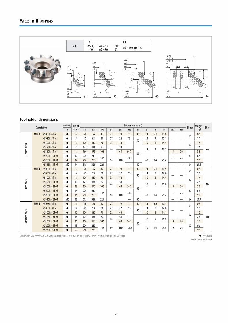
Face mill MFPN45
: Available
MTO: Made-To-Order
Dimension S: 6 mm (GM, SM, GH chipbreakers), 5 mm (GL chipbreaker), 3 mm (W chipbreaker: PR15 series)
Toolholder dimensions
DescriptionAvailability No. of
insertsDimensions (mm)
Shape Weight(kg) Shim
R øD øD1 øD2 ød ød1 ød2 H E a b ød3 ød4
Coar
se pi
tch
MFPN 45063R-4T-M 4 63 76 47 22 19 11 40 21 6.3 10.4
— —#1
0.5
Yes
45080R-5T-M 5 80 93 60 27 22 1350
24 7 12.4 1.145100R-6T-M 6 100 113 70 32 48
—30 8 14.4
#21.4
45125R-7T-M 7 125 138 8740
58
6332 9 16.4
2.645160R-8T-M 8 160 173 102 68 66.7 14 20
#33.8
45200R-10T-M 10 200 213142
60 110101.6
40 14 25.718 26
6.445250R-12T-M 12 250 263 9.145315R-14T-M MTO 14 315 328 220 — 80 — — #4 21.3
Fine p
itch
MFPN 45063R-5T-M 5 63 76 47 22 19 11 40 21 6.3 10.4
— —#1
0.5
No
45080R-6T-M 6 80 93 60 27 22 1350
24 7 12.4 1.0 45100R-8T-M 8 100 113 70 32 48
—30 8 14.4
#21.4
45125R-10T-M 10 125 138 8740
58
6332 9 16.4
2.545160R-12T-M 12 160 173 102 68 66.7 14 20
#33.8
45200R-14T-M 14 200 213142
60 110101.6
40 14 25.718 26
6.545250R-16T-M 16 250 263 9.145315R-18T-M MTO 18 315 328 220 — 80 — — #4 21.7
Extra
fine p
itch
MFPN 45063R-6T-M 6 63 76 47 22 19 11 40 21 6.3 10.4
— —#1
0.5
No
45080R-8T-M 8 80 93 60 27 22 1350
24 7 12.4 1.145100R-10T-M 10 100 113 70 32 48
—30 8 14.4
#21.3
45125R-13T-M 13 125 138 8740
58
6332 9 16.4
2.645160R-16T-M 16 160 173 102 68 66.7 14 20
#33.9
45200R-18T-M 18 200 213142 60 110 101.6 40 14 25.7 18 26
6.645250R-20T-M 20 250 263 9.3
A.R.A.R. R.R.
(MAX.)+10°
øD = 63 -10°øD = 80 -8° øD = 100-315 -6°
HS
bød
øD2
ød2ød1øDøD1
bød
a
HS
øDøD1
E
Ea
ød1
HS
øDøD1
bød
ød3
ø26
ød2
ød1
E
a
S
øDøD1
H
ø22ø18
ø32
bød
ø177.8
ød1
E
ø101.6
a
ød4
#1 #2 #3 #4
øD2øD2
øD2
Dimension S: 6 mm (GM, SM, GH chipbreakers), 5 mm (GL chipbreaker), 3 mm (W chipbreaker: PR15 series)Coat anti-seize compound (MP-1) thinly on portion of taper and thread prior to installation.
Toolholder dimensions
Description
Avail
abilit
y
No. of inserts
Dimensions (mm) A.R. Spare partsClamp screw Wrench Anti-Seize compound
øD øD1 ød L ℓ S A.R.(MAX.) R.R.
MFPN 45050R-S32-3T 3 50 6332 110 30
6(5)
+10°-12° SB-50140TR TTW-15
P-3745063R-S32-4T 4 63 76 -10°45080R-S32-5T 5 80 93 -8°
: Available
Recommended torque is 4.2 N • m
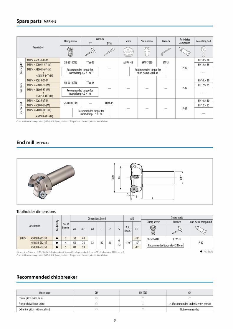
End mill MFPN45
Recommended chipbreaker
Cutter type GM SM (GL) GH
Coarse pitch (with shim)
Fine pitch (without shim) (Recommended under fz = 0.4 mm/t)
Extra fine pitch (without shim) Not recommended
Spare parts MFPN45
Description
Clamp screwWrench
Shim Shim screw Wrench Anti-Seize compound Mounting bolt
TT DTM
Coar
se pi
tch
MFPN 45063R-4T-MSB-50140TR TTW-15
—
MFPN-45 SPW-7050 LW-5
P-37
HH10 × 30MFPN 45080R/L-5T-(M) HH12 × 35MFPN 45100R/L-6T-(M)~
45315R-14T-(M)—
Fine p
itch
MFPN 45063R-5T-MSB-50140TR TTW-15
— — — — P-37
HH10 × 30MFPN 45080R-6T-(M) HH12 × 35MFPN 45100R-8T-(M)~
45315R-18T-(M)—
Extra
fine p
itch MFPN 45063R-6T-M
SB-40140TRN — DTM-15
— — — P-37
HH10 × 30MFPN 45080R-8T-(M) HH12 × 35MFPN 45100R-10T-(M)~
45250R-20T-(M)—
Recommended torque for insert clamp 4.2 N · m
Recommended torque for shim clamp 6.0 N · m
Recommended torque for insert clamp 4.2 N · m
Recommended torque for insert clamp 3.5 N · m
Coat anti-seize compound (MP-1) thinly on portion of taper and thread prior to installation.
5
ødh6
Sℓ
L
øDøD1
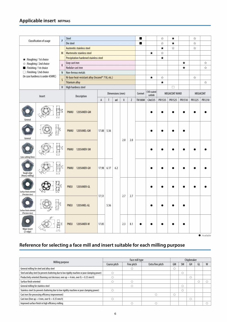
Classification of usage PSteel
Die steel
: Roughing / 1st choice : Roughing / 2nd choice : Finishing / 1st choice : Finishing / 2nd choice
(In case hardness is under 45HRC)
M
Austenitic stainless steel
Martensitic stainless steel
Precipitation hardened stainless steel
KGray cast iron
Nodular cast iron
N Non-ferrous metals
SNi-base heat-resistant alloy (Inconel® 718, etc.)
Titanium alloy
H High hardness steel
Insert DescriptionDimensions (mm) Cermet CVD coated
carbide MEGACOAT NANO MEGACOAT
A T ød X Z TN100M CA6535 PR1535 PR1525 PR1510 PR1225 PR1210
General
PNMU 1205ANER-GM
17.88 5.56
6.2
2.0 2.0General
PNMU 1205ANEL-GM
Low cutting force
PNMU 1205ANER-SM
Tough edge(Heavy milling)
PNMU 1205ANER-GH 17.98 6.17
Surface finish oriented(Precision class)
PNEU 1205ANER-GL
17.51
5.56
2.7 2.7
Surface finish oriented(Precision class)
PNEU 1205ANEL-GL
Wiper insert(2-edge)
PNEU 1205ANER-W 17.85 2.3 8.1
: Available
Applicable insert MFPN45
Milling purposeFace mill type Chipbreaker
Coarse pitch Fine pitch Extra fine pitch GM SM GH GL WGeneral milling for steel and alloy steel
Steel and alloy steel (to prevent chattering due to low rigidity machine or poor clamping power)
Productivity oriented (Running cost decrease; over ap = 4 mm, over fz = 0.35 mm/t)
Surface finish oriented
General milling for stainless steel
Stainless steel (to prevent chattering due to low rigidity machine or poor clamping power)
Cast iron (for processing efficiency improvement)
Cast iron (Over ap = 4 mm, over fz = 0.35 mm/t)
Improved surface finish in high efficiency milling
Reference for selecting a face mill and insert suitable for each milling purpose
6
A
T
Z
X
ødød
T
A
Z
X
A ød
TX
Z
ødA
T
r600
X
Z
A ød
TX
Z
ød
T
A
Z
X
A ød
TX
Z
Chipbreaker combination Insert Surface finish Workpiece surface
MFPN wiper insertPR1525
(PNMU-GM…9 inserts)(PNEU-W…1 inserts)
Ra = 0.48 μmRz = 3.39 μm
Shiny surface
MFPN GL chipbreakerPR1225
(PNEU-GL…10 inserts)
Ra = 2.50 μmRz = 11.41 μm
Shiny surface
Improved surface finish with wiper insert
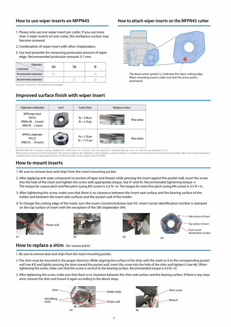
How to use wiper inserts on MFPN45 How to attach wiper inserts on the MFPN45 cutter
1. Please only use one wiper insert per cutter. If you use more than 2 wiper inserts on one cutter, the workpiece surface may become smeared.
2. Combination of wiper insert with other chipbreakers.
3. Use tool presetter for measuring protrusion amount of wiper edge. Recommended protrusion amount: 0.1 mm.
MFPN45125R-10T (10 inserts). Cutting conditions: Vc = 200 m/min-1 (n = 510 min-1), fz = 0.2 mm/t (Vf = 1,020 mm/min), ap × ae = 3 × 100 mm, dry, workpiece: 17Cr3Results above are from an internal evaluation. The surface roughness also depends on the workpiece, cutting conditions or conditions according to the actual machining situation. When the surface roughness is unstable, please set the cutting speed higher, the feed rate lower, or use a wiper insert (TN100M).
How to replace a shim (for coarse pitch)
How to mount inserts
Shim
Identifying mark
Holder body
Pocket wall
#5
Shim screw
Wrench
#6
ChipbreakerCombination
GM SM W
Recommended combination
Recommended combination
Using GH + W and GL + W are NOT recommended.
1. Be sure to remove dust and chips from the insert mounting pocket.
2. After applying anti-seize compound on portion of taper and thread, while pressing the insert against the pocket wall, insert the screw into the hole of the insert and tighten the screw with appropriate torque. See #1 and #2. Recommended tightening torque The torque for coarse pitch and fine pitch (using M5 screw) is 4.2 N • m. The torque for extra fine pitch (using M4 screw) is 3.5 N • m.
3. After tightening the screw, make sure that there is no clearance between the insert seat surface and the bearing surface of the holder and between the insert side surfaces and the pocket wall of the holder.
4. To change the cutting edge of the insert, turn the insert counterclockwise (see #3). Insert corner identification number is stamped on the top surface of insert with the exception of the SM chipbreaker (#4).
#2
Pocket wall
#1 #3 #4
Side surface of insert
Top surface of insert
Insert corner identification number
1. Be sure to remove dust and chips from the insert mounting pocket.
2. The shim must be mounted in the proper direction. While aligning the surface of the shim with the mark on it to the corresponding pocket wall (see #5) and lightly pressing the shim toward the pocket wall, insert the screw into the hole of the shim and tighten it (see #6). When tightening the screw, make sure that the screw is vertical to the bearing surface. Recommended torque is 6.0 N • m.
3. After tightening the screw, make sure that there is no clearance between the shim seat surface and the bearing surface. If there is any clear-ance, remove the shim and mount it again according to the above steps.
7
The down arrow symbol ( ) indicates the wiper cutting edge.When mounting inserts, make sure that the arrow points downward.
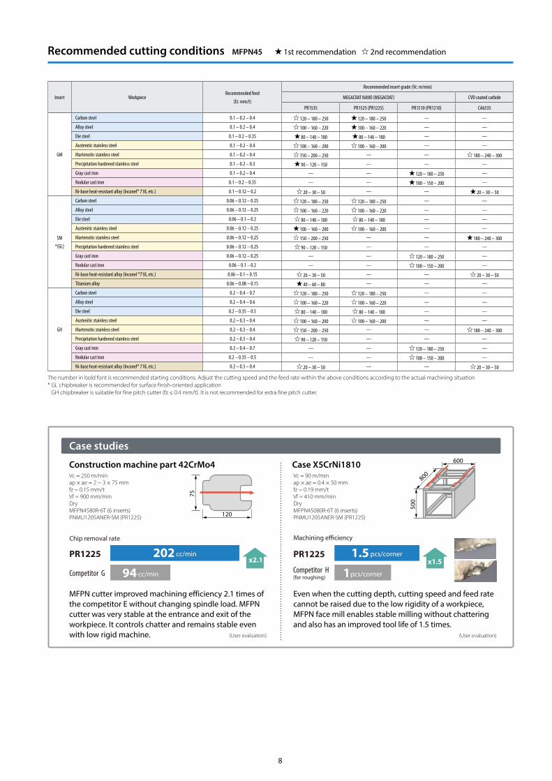
Recommended cutting conditions MFPN45 1st recommendation 2nd recommendation
Insert WorkpieceRecommended feed
(fz: mm/t)
Recommended insert grade (Vc: m/min)
MEGACOAT NANO (MEGACOAT) CVD coated carbide
PR1535 PR1525 (PR1225) PR1510 (PR1210) CA6535
GM
Carbon steel 0.1 – 0.2 – 0.4 120 – 180 – 250 120 – 180 – 250 — —
Alloy steel 0.1 – 0.2 – 0.4 100 – 160 – 220 100 – 160 – 220 — —
Die steel 0.1 – 0.2 – 0.35 80 – 140 – 180 80 – 140 – 180 — —
Austenitic stainless steel 0.1 – 0.2 – 0.4 100 – 160 – 200 100 – 160 – 200 — —
Martensitic stainless steel 0.1 – 0.2 – 0.4 150 – 200 – 250 — — 180 – 240 – 300
Precipitation hardened stainless steel 0.1 – 0.2 – 0.3 90 – 120 – 150 — — —
Gray cast iron 0.1 – 0.2 – 0.4 — — 120 – 180 – 250 —
Nodular cast iron 0.1 – 0.2 – 0.35 — — 100 – 150 – 200 —
Ni-base heat-resistant alloy (Inconel® 718, etc.) 0.1 – 0.12 – 0.2 20 – 30 – 50 — — 20 – 30 – 50
SM
*(GL)
Carbon steel 0.06 – 0.12 – 0.25 120 – 180 – 250 120 – 180 – 250 — —
Alloy steel 0.06 – 0.12 – 0.25 100 – 160 – 220 100 – 160 – 220 — —
Die steel 0.06 – 0.1 – 0.2 80 – 140 – 180 80 – 140 – 180 — —
Austenitic stainless steel 0.06 – 0.12 – 0.25 100 – 160 – 200 100 – 160 – 200 — —
Martensitic stainless steel 0.06 – 0.12 – 0.25 150 – 200 – 250 — — 180 – 240 – 300
Precipitation hardened stainless steel 0.06 – 0.12 – 0.25 90 – 120 – 150 — — —
Gray cast iron 0.06 – 0.12 – 0.25 — — 120 – 180 – 250 —
Nodular cast iron 0.06 – 0.1 – 0.2 — — 100 – 150 – 200 —
Ni-base heat-resistant alloy (Inconel ®718, etc.) 0.06 – 0.1 – 0.15 20 – 30 – 50 — — 20 – 30 – 50
Titanium alloy 0.06 – 0.08 – 0.15 40 – 60 – 80 — — —
GH
Carbon steel 0.2 – 0.4 – 0.7 120 – 180 – 250 120 – 180 – 250 — —
Alloy steel 0.2 – 0.4 – 0.6 100 – 160 – 220 100 – 160 – 220 — —
Die steel 0.2 – 0.35 – 0.5 80 – 140 – 180 80 – 140 – 180 — —
Austenitic stainless steel 0.2 – 0.3 – 0.4 100 – 160 – 200 100 – 160 – 200 — —
Martensitic stainless steel 0.2 – 0.3 – 0.4 150 – 200 – 250 — — 180 – 240 – 300
Precipitation hardened stainless steel 0.2 – 0.3 – 0.4 90 – 120 – 150 — — —
Gray cast iron 0.2 – 0.4 – 0.7 — — 120 – 180 – 250 —
Nodular cast iron 0.2 – 0.35 – 0.5 — — 100 – 150 – 200 —
Ni-base heat-resistant alloy (Inconel® 718, etc.) 0.2 – 0.3 – 0.4 20 – 30 – 50 — — 20 – 30 – 50
Case studies
Construction machine part 42CrMo4 Case X5CrNi1810Vc = 250 m/minap × ae = 2 ~ 3 × 75 mmfz = 0.15 mm/tVf = 900 mm/minDryMFPN4580R-6T (6 inserts)PNMU1205ANER-SM (PR1225)
MFPN cutter improved machining efficiency 2.1 times of the competitor E without changing spindle load. MFPN cutter was very stable at the entrance and exit of the workpiece. It controls chatter and remains stable even with low rigid machine. (User evaluation)
Chip removal rate
202 cc/min
94 cc/min
x2.1PR1225
Competitor G
120
75
Vc = 90 m/minap × ae = 0.4 × 50 mmfz = 0.19 mm/tVf = 410 mm/minDryMFPN45080R-6T (6 inserts)PNMU1205ANER-SM (PR1225)
Even when the cutting depth, cutting speed and feed rate cannot be raised due to the low rigidity of a workpiece, MFPN face mill enables stable milling without chattering and also has an improved tool life of 1.5 times. (User evaluation)
1.5 pcs/corner
1pcs/corner
x1.5PR1225
Competitor H(for roughing)
Machining e�ciency
500
600
800
The number in bold font is recommended starting conditions. Adjust the cutting speed and the feed rate within the above conditions according to the actual machining situation* GL chipbreaker is recommended for surface finish-oriented application GH chipbreaker is suitable for fine pitch cutter (fz ≤ 0.4 mm/t). It is not recommended for extra fine pitch cutter.
8
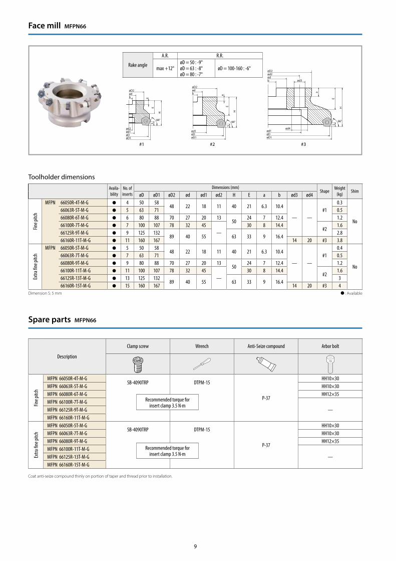
Face mill MFPN66
Toolholder dimensions
Availa- bility
No. of inserts
Dimensions (mm)Shape
Weight(kg)
ShimøD øD1 øD2 ød ød1 ød2 H E a b ød3 ød4
Fine p
itch
MFPN 66050R-4T-M-G 4 50 5848 22 18 11 40 21 6.3 10.4
— —#1
0.3
No
66063R-5T-M-G 5 63 71 0.566080R-6T-M-G 6 80 88 70 27 20 13
5024 7 12.4 1.2
66100R-7T-M-G 7 100 107 78 32 45—
30 8 14.4#2
1.666125R-9T-M-G 9 125 132
89 40 55 63 33 9 16.42.8
66160R-11T-M-G 11 160 167 14 20 #3 3.8
Extra
fine p
itch
MFPN 66050R-5T-M-G 5 50 5848 22 18 11 40 21 6.3 10.4
— —#1
0.4
No
66063R-7T-M-G 7 63 71 0.566080R-9T-M-G 9 80 88 70 27 20 13
5024 7 12.4 1.2
66100R-11T-M-G 11 100 107 78 32 45—
30 8 14.4#2
1.666125R-13T-M-G 13 125 132
89 40 55 63 33 9 16.43
66160R-15T-M-G 15 160 167 14 20 #3 4 : Available
Rake angle
A.R. R.R.
max +12°øD = 50 : -9°øD = 63 : -8°øD = 80 : -7°
øD = 100-160 : -6°
Spare parts MFPN66
Description
Clamp screw Wrench Anti-Seize compound Arbor bolt
Fine p
itch
MFPN 66050R-4T-M-GSB-4090TRP DTPM-15
P-37
HH10×30MFPN 66063R-5T-M-G HH10×30MFPN 66080R-6T-M-G HH12×35MFPN 66100R-7T-M-G
—MFPN 66125R-9T-M-GMFPN 66160R-11T-M-G
Extra
fine p
itch
MFPN 66050R-5T-M-GSB-4090TRP DTPM-15
P-37
HH10×30MFPN 66063R-7T-M-G HH10×30MFPN 66080R-9T-M-G HH12×35MFPN 66100R-11T-M-G
—MFPN 66125R-13T-M-GMFPN 66160R-15T-M-G
Recommended torque for insert clamp 3.5 N·m
Recommended torque for insert clamp 3.5 N·m
Coat anti-seize compound thinly on portion of taper and thread prior to installation.
Dimension S: 5 mm
ød2ød1øDøD1
øD2ødb
ød1øDøD1
øD2ødb
a
E
H
S 66°66°
a
E
H
S
ød1ød4
øDøD1
øD2ød2
ød3ødb
66°
a
E
H
S
#1 #2 #3
9
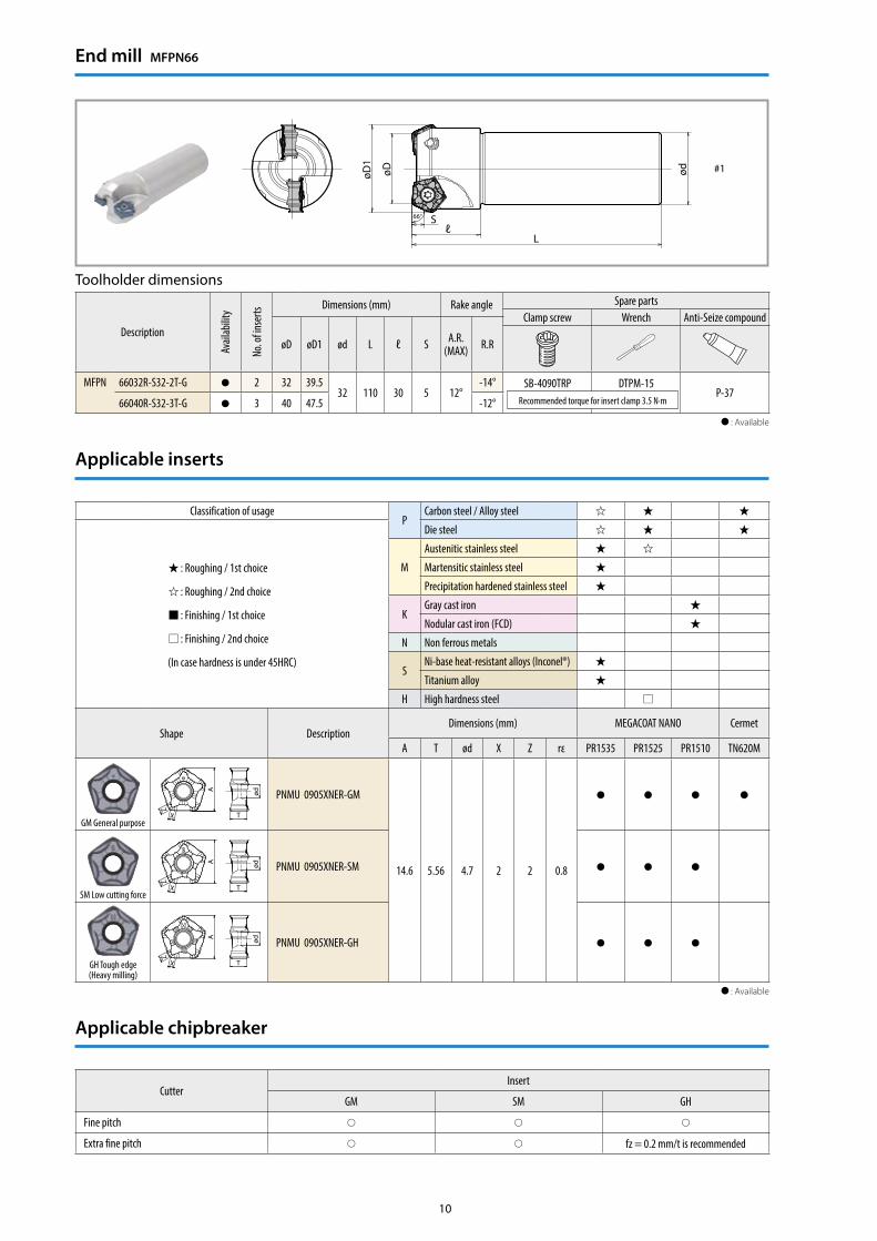
Toolholder dimensions
Description
Avail
abilit
y
No. o
f inse
rts
Dimensions (mm) Rake angle Spare partsClamp screw Wrench Anti-Seize compound
øD øD1 ød L ℓ S A.R.(MAX) R.R
MFPN 66032R-S32-2T-G 2 32 39.532 110 30 5 12°
-14° SB-4090TRP DTPM-15P-37
66040R-S32-3T-G 3 40 47.5 -12° : Available
Recommended torque for insert clamp 3.5 N·m
End mill MFPN66
Applicable chipbreaker
CutterInsert
GM SM GH
Fine pitch
Extra fine pitch fz = 0.2 mm/t is recommended
Classification of usageP
Carbon steel / Alloy steel
: Roughing / 1st choice
: Roughing / 2nd choice
: Finishing / 1st choice
: Finishing / 2nd choice
(In case hardness is under 45HRC)
Die steel
M
Austenitic stainless steel
Martensitic stainless steel
Precipitation hardened stainless steel
KGray cast iron
Nodular cast iron (FCD)
N Non ferrous metals
SNi-base heat-resistant alloys (Inconel®)
Titanium alloy
H High hardness steel
Shape DescriptionDimensions (mm) MEGACOAT NANO Cermet
A T ød X Z rε PR1535 PR1525 PR1510 TN620M
GM General purpose
A
T
Z
X
ød PNMU 0905XNER-GM
14.6 5.56 4.7 2 2 0.8
SM Low cutting force
A
T
Z
X
ød PNMU 0905XNER-SM
GH Tough edge(Heavy milling)
A
T
Z
X
ød PNMU 0905XNER-GH
: Available
Applicable inserts
øD1
øD ød
Sℓ
L
66°
#1
10
The information contained in this brochure is current as of September 2017.Duplication or reproduction of any part of this brochure without approval is prohibited.
TZE00109© 2017 KYOCERA Corporationwww.kyocera-unimerco.com
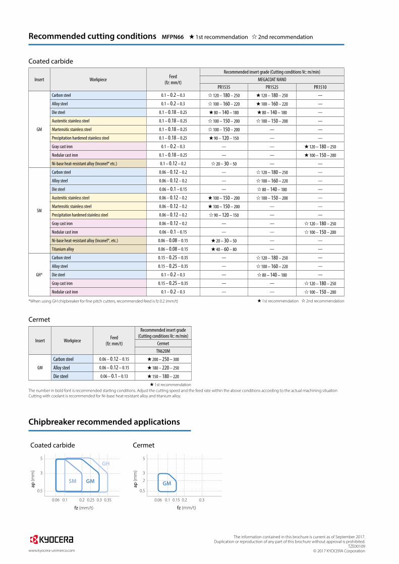
Recommended cutting conditions MFPN66 1st recommendation 2nd recommendation
Insert Workpiece Feed(fz: mm/t)
Recommended insert grade (Cutting conditions Vc: m/min) MEGACOAT NANO
PR1535 PR1525 PR1510
GM
Carbon steel 0.1 – 0.2 – 0.3 120 – 180 – 250 120 – 180 – 250 —
Alloy steel 0.1 – 0.2 – 0.3 100 – 160 – 220 100 – 160 – 220 —
Die steel 0.1 – 0.18 – 0.25 80 – 140 – 180 80 – 140 – 180 —
Austenitic stainless steel 0.1 – 0.18 – 0.25 100 – 150 – 200 100 – 150 – 200 —
Martensitic stainless steel 0.1 – 0.18 – 0.25 100 – 150 – 200 — —
Precipitation hardened stainless steel 0.1 – 0.18 – 0.25 90 – 120 – 150 — —
Gray cast iron 0.1 – 0.2 – 0.3 — — 120 – 180 – 250
Nodular cast iron 0.1 – 0.18 – 0.25 — — 100 – 150 – 200
Ni-base heat-resistant alloy (Inconel® etc.) 0.1 – 0.12 – 0.2 20 – 30 – 50 — —
SM
Carbon steel 0.06 – 0.12 – 0.2 — 120 – 180 – 250 —
Alloy steel 0.06 – 0.12 – 0.2 — 100 – 160 – 220 —
Die steel 0.06 – 0.1 – 0.15 — 80 – 140 – 180 —
Austenitic stainless steel 0.06 – 0.12 – 0.2 100 – 150 – 200 100 – 150 – 200 —
Martensitic stainless steel 0.06 – 0.12 – 0.2 100 – 150 – 200 — —
Precipitation hardened stainless steel 0.06 – 0.12 – 0.2 90 – 120 – 150 — —
Gray cast iron 0.06 – 0.12 – 0.2 — — 120 – 180 – 250
Nodular cast iron 0.06 – 0.1 – 0.15 — — 100 – 150 – 200
Ni-base heat-resistant alloy (Inconel®, etc.) 0.06 – 0.08 – 0.15 20 – 30 – 50 — —
Titanium alloy 0.06 – 0.08 – 0.15 40 – 60 – 80 — —
GH*
Carbon steel 0.15 – 0.25 – 0.35 — 120 – 180 – 250 —
Alloy steel 0.15 – 0.25 – 0.35 — 100 – 160 – 220 —
Die steel 0.1 – 0.2 – 0.3 — 80 – 140 – 180 —
Gray cast iron 0.15 – 0.25 – 0.35 — — 120 – 180 – 250
Nodular cast iron 0.1 – 0.2 – 0.3 — — 100 – 150 – 200
1st recommendation 2nd recommendation
The number in bold font is recommended starting conditions. Adjust the cutting speed and the feed rate within the above conditions according to the actual machining situationCutting with coolant is recommended for Ni-base heat resistant alloy and titanium alloy.
*When using GH chipbreaker for fine pitch cutters, recommended feed is fz 0.2 (mm/t)
Coated carbide
Cermet
Coated carbide Cermet
Insert Workpiece Feed(fz: mm/t)
Recommended insert grade (Cutting conditions Vc: m/min)
CermetTN620M
GM
Carbon steel 0.06 – 0.12 – 0.15 200 – 250 – 300
Alloy steel 0.06 – 0.12 – 0.15 180 – 220 – 250
Die steel 0.06 – 0.1 – 0.13 150 – 180 – 220
1st recommendation
Chipbreaker recommended applications
ap (m
m)
fz (mm/t)
5
3
0.5
0.1 0.2 0.30.25 0.350.06
SM
GH
GM
ap (m
m)
fz (mm/t)
5
3
2
0.5
0.06 0.1 0.15 0.2 0.3
GM
Recommended