J. H. Burge University of Arizona
1
• Most of the small (<1 m) parts for optics are made by cutting from oversized stock on a few common machines. These can be driven by a skilled operator, or by numerical control:
• Milling machine (aka “mill” or “Bridgeport”) • Lathe • Drill press
Other processes are used as needed: • Near net shape forming (Rolling, casting, extruding, stamping) • Surfacing (bead blasting, grinding, lapping) • Welding, brazing • EDM (Electrical discharge machining) • Precision cutting (Laser, abrasive water jet)
Different materials have very different limitations – Get to know the guys in the shop
Manufacturing and metrology of mechanical parts
J. H. Burge University of Arizona
2
Rules of thumb for machined parts ± 1 mm for coarse dimensions that are not important (0.040 inches or “forty thousandths”) ± 0.25 mm for typical machining without difficulty (0.010 inches or “ten thousandths””) ± 0.025 mm precision machining, readily accessible (0.001” inches or “one thousandths” or “1 mil”) < ± 0.002 mm high-precision, requires special tooling (0.0001” or “one ten-thousandths” or “one tenth” or
“one hundred millionths”)
J. H. Burge University of Arizona
3
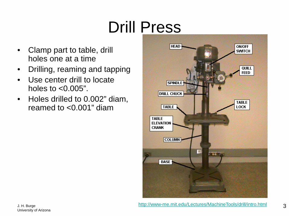
Drill Press • Clamp part to table, drill
holes one at a time • Drilling, reaming and tapping • Use center drill to locate
holes to <0.005”. • Holes drilled to 0.002” diam,
reamed to <0.001” diam
http://www-me.mit.edu/Lectures/MachineTools/drill/intro.html
J. H. Burge University of Arizona
4
Milling machine
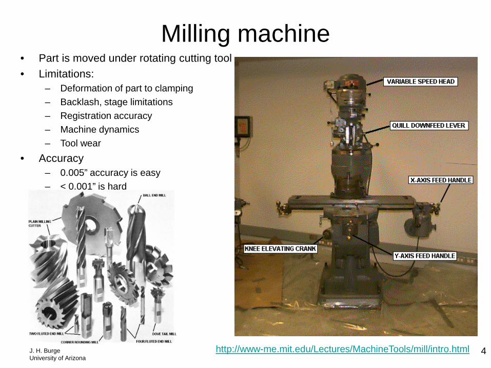
http://www-me.mit.edu/Lectures/MachineTools/mill/intro.html
• Part is moved under rotating cutting tool • Limitations:
– Deformation of part to clamping – Backlash, stage limitations – Registration accuracy – Machine dynamics – Tool wear
• Accuracy – 0.005” accuracy is easy – < 0.001” is hard
J. H. Burge University of Arizona
5
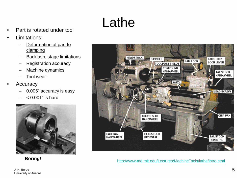
Lathe
http://www-me.mit.edu/Lectures/MachineTools/lathe/intro.html
• Part is rotated under tool • Limitations:
– Deformation of part to clamping
– Backlash, stage limitations – Registration accuracy – Machine dynamics – Tool wear
• Accuracy – 0.005” accuracy is easy – < 0.001” is hard
Boring!
J. H. Burge University of Arizona
6
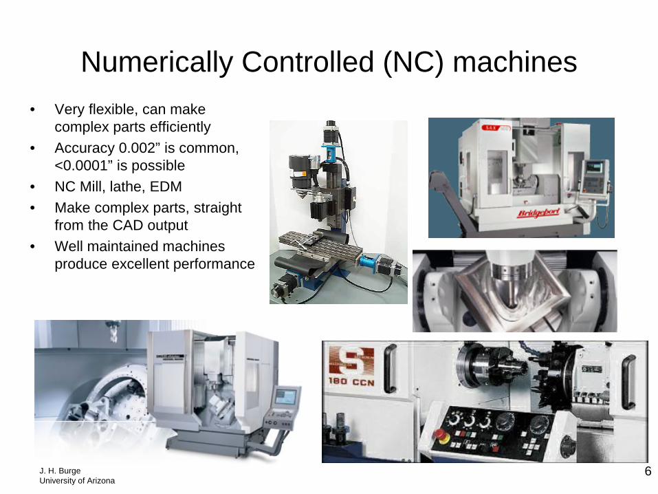
Numerically Controlled (NC) machines • Very flexible, can make
complex parts efficiently • Accuracy 0.002” is common,
<0.0001” is possible • NC Mill, lathe, EDM • Make complex parts, straight
from the CAD output • Well maintained machines
produce excellent performance
J. H. Burge University of Arizona
7
Common tools for measuring length • Plastic ruler: Good for quick, rough measurements. Most practical measurements in the lab will be
made with the ruler. Be careful -- the end of the ruler usually does not coincide with the 0 mark • Steel rule: Allows much more accuracy, costs more. • Tape measure: Good for quick measurements over wide distance variations. High quality surveying
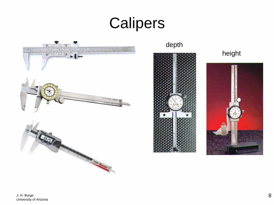
tapes can be used for measuring over dozens of meters to sub-millimeter accuracy. • Calipers: These are common, inexpensive, fairly accurate, and versatile. Use them for measuring
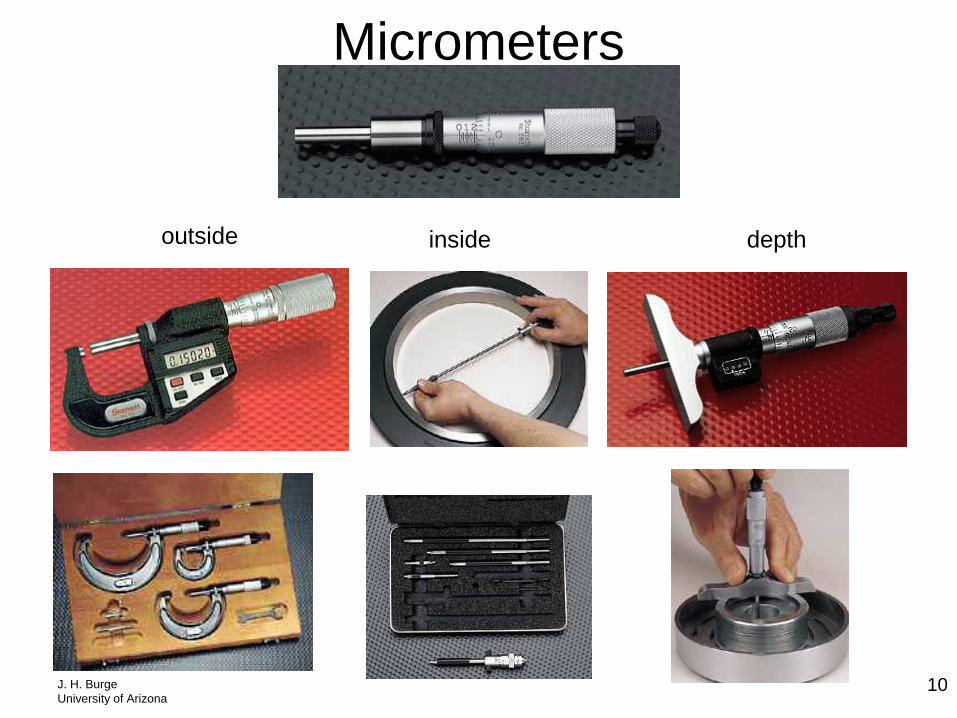
outside dimensions, inside dimensions, and depth. • Height gage: Usually used on a flat granite table. Measures height from ~1 to 30 inches • Micrometer: This is a fine pitch screw with accurate marks. Use the vernier for highest accuracy. • Outside micrometers: A frame holding a micrometer for measuring outside dimensions. These can be
purchased for measuring up to about 10 inches. • Inside micrometers: Holds a micrometer for measuring inside dimensions. These are made with
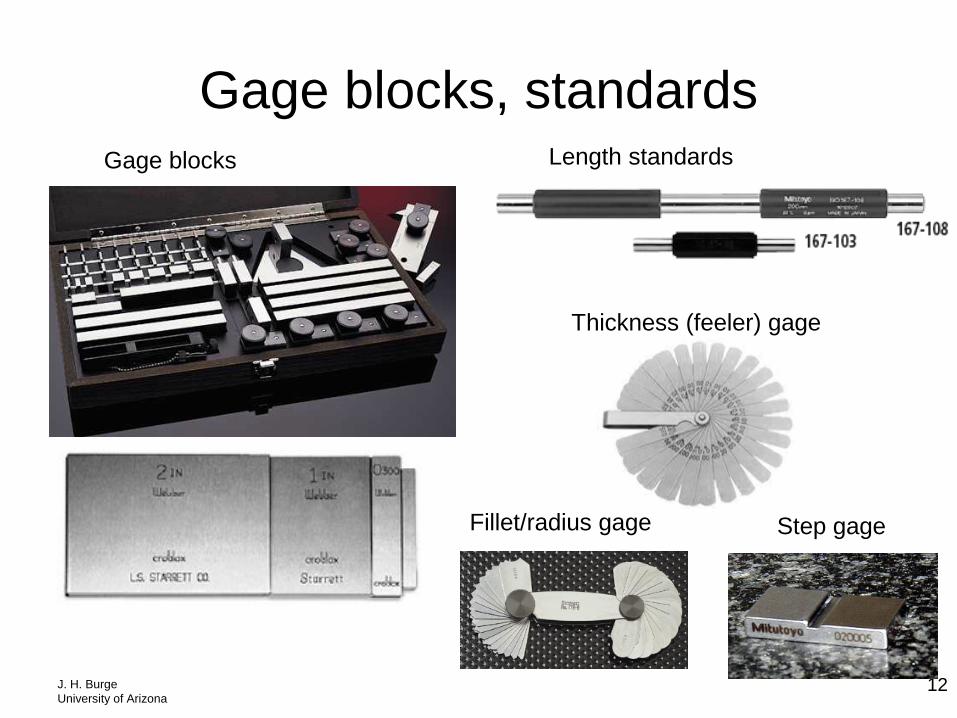
extensions that can be put together for measuring up to 20 feet. • Gage blocks: Highly accurate for defining length standards for 0.1 – 4 inches. Special length standards
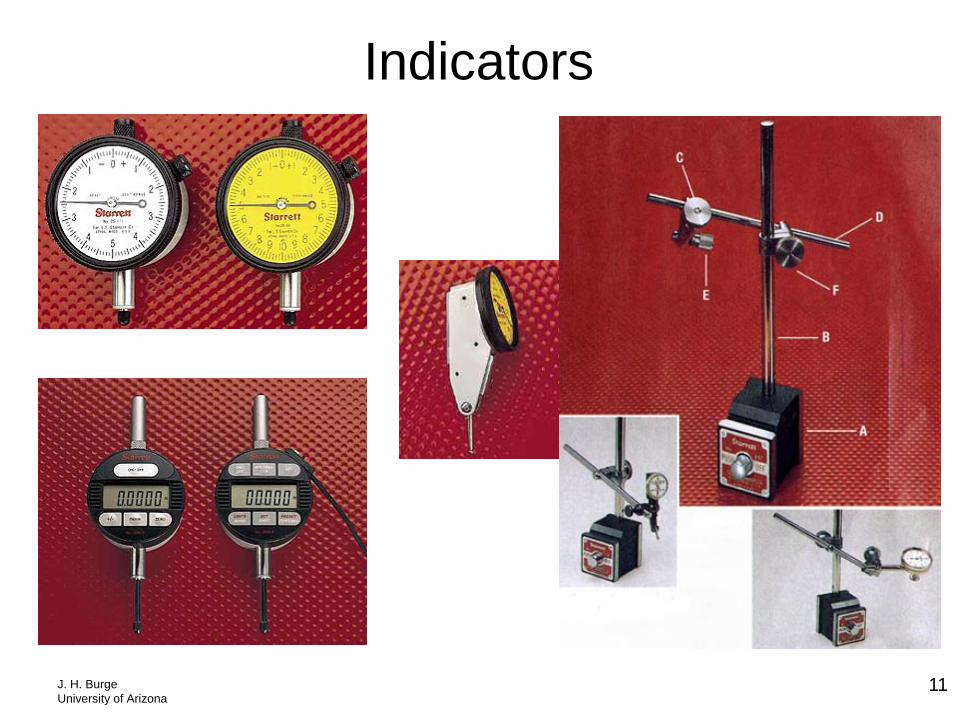
can be purchased for much longer distances. • Indicator: Can be digital or dial. Often used for measuring motion, such as runout on a spindle • Depth gage: Uses a micrometer or indicator to measure depth. • Telescoping gages: Measures small gaps, calibrate with outside micrometer
J. H. Burge University of Arizona
8
Calipers depth
height
J. H. Burge University of Arizona
9
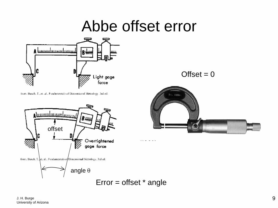
Abbe offset error
Error = offset * angle angle θ
offset
Offset = 0
J. H. Burge University of Arizona
10
Micrometers
outside inside depth
J. H. Burge University of Arizona
11
Indicators
J. H. Burge University of Arizona
12
Gage blocks, standards Gage blocks
Fillet/radius gage Step gage
Length standards
Thickness (feeler) gage
J. H. Burge University of Arizona
13
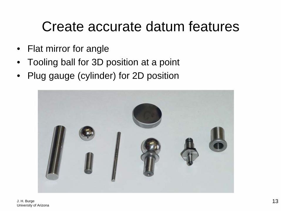
Create accurate datum features • Flat mirror for angle • Tooling ball for 3D position at a point • Plug gauge (cylinder) for 2D position
J. H. Burge University of Arizona
14
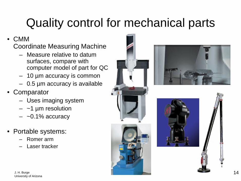
Quality control for mechanical parts • CMM
Coordinate Measuring Machine – Measure relative to datum
surfaces, compare with computer model of part for QC
– 10 µm accuracy is common – 0.5 µm accuracy is available
• Comparator – Uses imaging system – ~1 µm resolution – ~0.1% accuracy
• Portable systems:
– Romer arm – Laser tracker
Recommended