HUGHES
HUGHES DANBURY OPTICAL SYSTEMS, INC.a subsidiary
PR D15-0015
LUTE TELESCOPE STRUCTURAL DESIGN
STUDY REPORT
MAY 1993
Prepared for:
National Aeronautics and Space Administration
George C. Marshall Space Flight Center
Marshall Space Flight CenterAlabama 35812
Order No. H-19671D
HUGHES DANBURY OPTICAL SYSTEMS, INC.100 WOOSTER HEIGHTS ROADDANBURY. CT 06810-7589
(NASA-CR-192594) LUTF TELESCOPE
STRUCTURAL DESIGN Study Report
(Huqhes Oanbury ODtica| Systems)53 P
N9_-13448
Unclas
G3/89 0180886
https://ntrs.nasa.gov/search.jsp?R=19940008975 2018-05-20T23:15:27+00:00Z

HUGHES
HUGHES DANBURY OPTICAL SYSTEMS, INC.
a subsidiary
PR DI5-0015
LUTE TELESCOPE STRUCTURAL DESIGN
STUDY REPORT
MAY lg93
Prepared for:
National Aeronautics and Space Administration
George C. Marshall Space Flight Center
Marshall Space Flight CenterAlabama 35812
Order No. H-19671D
HUGHES DANBURY OPTICAL SYSTEMS. INC.100 WOOSTER HEIGHTS ROAD
DANBURY. CT 06810-7589

HUGHES
Hughes Danbury Optical Systems, Inc.a subsidiary
Project Report No.: PR D15-0015
Title: LUTE Telescope Design Study Report
Prepared by:
Ore ',u en,ProjectEn_cer
Approved by:
Approved by:
i t")/'
Mar_ steer, Program Manager
Advanced Development Lab
REVISION RECORD:
Revision Date
Release July 12, 1993
Affected Pages
i through v, 1-1, 2-1,
3-1 through 3-14
4-I through 4-4,
5-1 through 5-4,6-1, A-i

HUGHES
Hughes Danbury Optical Systems, Inc.a subsidiary
PR DlS-O01$
TABLE OF CONTENTS
Section Title
INTRODUCTION .......................................................................
2 SUMMARY OF RESULTS ........................................................
3
3.13.23.33.43.53.63.7
4
4.14.2
UVTA DESIGN DESCRIFTION AND STRUCTURALANALYSES ................................................................................
Study Logic .............................................................................Primary/Tertiary Mirrors ....................................................Secondary Mirror Assembly (SMA) ..................................Baffles ......................................................................................
Metering Structure Assembly ............................................Main Bulkhead ......................................................................
Weight Estimates ..................................................................
PRIMARY-TO-SECONDARY MIRROR DESPACEPREDICTIONS ...........................................................................
Thermally Induced ...............................................................Secondary Mirror Focus Mechanism Range ...................
55.1
MECHANICAL LAYOUTS .......................................................Overall UTVA .......................................................................
6 RECOMMENDATIONS ............................................................
APPENDIX A LUTE VIEWGRAPHS FROM 4 MAY 1993TECHNICAL TELECON ..........................................................
Page
1-1
2-1
3-13-13-33-53-8
3-103-123-13
4-14-14-3
5-15-1
6-1
A-I
-- iii

HUGHES
Hughes Danbury Optical Systems, Ino,
a subsidiary
PR 1)15-0015
LIST OF ILLUSTRATIONS
Figure
3-1
3-2
3-3
3-4
3-5
3-6
5-1
Title
Telescope Structural Configuration Trades Conductedin Order to Meet Strawman Set of Requirements .............
Our LUTE Telescope is Based on a 3 Mirror OpticalDesign and a Very Aggressive Weight Budget ...................
1.03 Meter f/1.0 LUTE Primary Mirror ...................................
0.3 Meter f/0.6 LUTE Tertiary Mirror .....................................
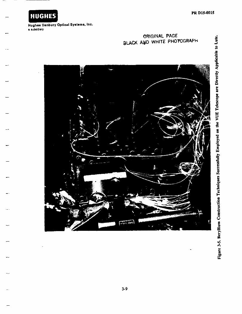
Beryllium Construction Techniques SuccessfullyEmployed on the VUE Telescope are DirectlyApplicable to LUTE ...................................................................
Results from Main Baffle NASTRAN Model Confirms
Design Meets Fundamental Frequency Requirements ....
The "Exploded" View of the LUTE Telescope ProvidesInsight into Assembly Sequences Along with Materialand Fabrication Techniques ....................................................
"Side" View of the LUTE Telescope .......................................
"Top" Views of the LUTE Telescope Sections "A-A"and "B-B" Highlights the Main Bulkhead andPrimary/Tertiary Mirrors, Respectively ..............................
Page
3-2
3-4
3-6
3-7
3-9
3-11
5-4
iv

HUGHES
Hughes Danbury Optical Systems, Inc.
a sul_id_y
PR D15-0015
LIST OF TABLES
Table
3-1
3-2
3-3
4-1
4-2
4-3
Title
A Consistent Set of Requirements Have BeenMaintained Throughout the LUTE Studies ........................
Fundamental Frequency Requirements Based onGround Testing Diagnostics and Spring-MassCoupling .....................................................................................
LUTE Calculated Weight Estimates Compared toAllocations and Assessed to Determine TelescopeFeasibility ....................................................................................
A Material with a Low CTE Over the Entire OperatingTemperature Range is Preferred So That WavefrontDistortions Caused by Telescope Axial TemperatureGradients are Minimized ........................................................
Scaled Results from a Similar Optical Design WereUsed to Calculate Allowable Telescope AxialTemperature Gradients ...........................................................
Identification of Despace Error Sources Have Been Made.Additional Analyses and Test Data Required to FullyQuantify These Effects on Optical Performance .................
Page
3-3
3-8
3-14
4-3
4-3
4-4
v

HUGHES
Hughes Danbury Optlcsl Systems, Inc.s subsidiary
PR DIS-O01S
SECTION 1
INTRODUCTION
The major objective of the Lunar Ultraviolet Transit Experiment (LUTE) TelescopeStructural Design Study was to investigate the feasibility of designing an ultra-lightweight 1-m aperture system within optical performance requirements and massbudget constraints. This study uses the results from our previous studies on LUTEas a basis for further developing the LUTE structural architecture.
After summarizing our results in Section 2, Section 3 begins with the overall logicwe used to determine which telescope "structural form" should be adopted for fur-ther analysis and weight estimates. Specific telescope component analysis showingcalculated fundamental frequencies and how they compare with our derived re-quirements are included. "First-order" component stress analyses to ensure tele-scope optical and structural component (i.e. mirrors & main bulkhead) weights arerealistic are presented. Layouts of both the primary and tertiary mirrors showingdimensions that are consistent with both our weight and frequency calculations also
form part of Section 3.
Section 4 presents our calculated values for the predicted thermally induced pri-mary-to-secondary mirror despace motion due to the large temperature range overwhich LUTE must operate. Two different telescope design approaches (one whichutilizes fused quartz metering rods and one which assumes the entire telescope isfabricated from beryllium) are considered in this analysis. We bound the secondarymirror focus mechanism range (in despace) based on these two telescopeconfigurations.
In Section 5 we show our overall design of the uV'rA (Ultraviolet TelescopeAssembly) via an "exploded view" of the sub-system. The "exploded view" is anno-tated to help aid in the understanding of each sub-assembly. We also include a twoview layout of the UVTA from which telescope and telescope component dimen-sions can be measured.
We conclude our study with a set of recommendations not only with respect to theLUTE structural architecture but also on other topics related to the overall feasibilityof the LUTE telescope sub-system.
1-1

HUGHES
Hughes Danbury Optical Systems, Inc.I iubsJdJary
PR D15-0015
SECTION 2
SUMMARY OF RESULTS
Based on this and the previous LUTE study, we remain convinced that the ability todesign, build, test and successfully launch and operate a 1-meter class diffractionlimited telescope operating over a large temperature range appears to be feasible.The major thrust of this study was to show that the telescope structural form or"architecture" could meet its weight and frequency allocation while still meeting itsoptical performance requirements. We have shown the weight and frequency re-quirements to be achievable by fabricating the telescope from beryllium. We havealso taken advantage of a telescope architecture which allows efficient use of theavailable weight by designing deterministic load paths which results in non-com-plex telescope interfaces. The secondary mirror focus mechanism range is dependenton a number of error sources which have been identified. We have estimated that
the anticipated range is well within that currently available (e.g. Hubble SpaceTelescope) and therefore does not represent a technology risk to the LUTE program.
After evaluating a number of telescope structural architectures we believe that atelescope which uses an "inverted tripod" metering structure in concert with a"single taper" primary mirror design can meet the stringent telescope sub-systemweight requirement of 84 kg even assuming a 18% weight contingency factor. Ourcalculated telescope sub-system weight is 83 kg including this factor. By adopting thisdesign approach significant weight savings are realized in the areas of the telescope
light baffle and main bulkhead. This design concept not only meets the weight re-quirement but meets the derived telescope fundamental frequency requirement of >50Hz. This design also affords us the ability to assemble and align the telescope sub-assemblies "off-line" so that parallel integration activities can take place.
As mentioned in our previous LUI_ study, the extreme temperature range (+ 100 K)over which the telescope must operate represents a significant challenge in terms ofmeeting wavefront requirements. Assuming this temperature range the secondarymirror focus mechanism should have a minimum despace range (i.e. travel along
the optical axis) of approximately +1 mm. As a point a reference, the HST focusmechanism has a range of approximately + 3 mm.
2-1

HUGHES
Hughes Danbury Optical Systems, Inc.a subsidiary
PR DI$-0015
SECTION 3
UVTA DESIGN DESCRIPTION ANDSTRUCTURAL ANALYSES
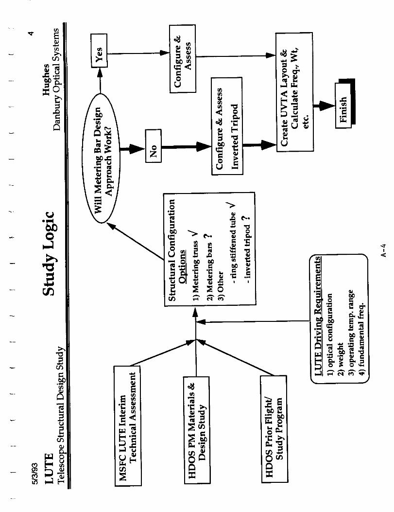
3.1 STUDY LOGIC
The logic used to assess the structural design of the Ultraviolet Telescope Assembly
(UVTA) is shown in Figure 3-1. We relied heavily on the results from the MSFCLUTE Interim Technical Assessment Report and the HDOS LUTE PM Material &
Design Study to formulate this logic. This included the assessment of the MSFC tele-scope structural architecture in terms of both weight and fundamental frequency
performance. The results of the Hubble Space Telescope-like metering truss design
approach used in the MSFC baseline design were used as a benchmark and point of
departure for our study.
Based on prior programs such as the Orbiting Solar Laboratory (OSL) where we stud-
ied several structural forms for a 1-m telescope, we qualitatively knew the perfor-
mance of a "ring-stiffened" metering structure as compared to the HST type struc-
ture. We therefore focused our attention on two other metering structure designs.
The first was a metering bar approach where low coefficient-of-thermal expansion
(CTE) material is used to maintain PM-to-SM spacing while decenter errors are min-
imized via a set of axial and tangential flexures. This structural configuration allows
the use of high CTE material (e.g. beryllium) to be used for the load carryingstructure.
The other configuration we investigated we termed an "inverted tripod" design
where the secondary mirror assembly (SMA) is supported via a metering structure
which utilizes the "real estate" between the PM and tertiary mirror (TM). This de-
sign approach has a disadvantage in that the metering structure locally obscures a
small portion of the converging optical beam at three locations. This is in contrast to
a more conventional telescope design which utilizes a SM spider. However we have
qualitatively discussed these effects and have determined this design approach to be
acceptable.
Our assessments of these two configurations were done in a serial logic form. We
made calculations to assess the metering bar and went through the logic "gate" on
whether this design option was warranted for further study. We concluded that
with the baseline beryllium optics which we recommended in the PM Design Study,
a metering design approach to the LUTE telescope did not display any advantages
3-1

HUGHES
Hughes Danbury Optical Systems, Inc.a subsidiary
PR D15-0015
MSFC LUTE InterimTechnicalAssessment
Will Metering Bar Des]
Approach Work7
HDOS PM Materials
& Design Study
HDOS Prior Flight/
Study Program
Structural Configuration
Ct tLmu1) Metering truss _/2) Metering bars ?3) Other
- ring stiffened tube "/
- inverted tripod ?
LUTE Driving Requirement _,,
1) optical configuration
2) weight
3) operating temp. range
4) fundamental freq.
Configure & IAssess
Configure & Assess]Inverted Tripod
late Freq., Wt, etc_
Finish
Figure 3-I. Telescope Structural Configuration Trades Conducted in Order to Meet SlzawmanSet of Requirements.
3-2

PR D15-0015HUGHES
Hughes Danbury Optical Systems, Inc.a subsidiary
(this is discussed further in Section 4). We therefore assessed the inverted tripod de-
sign and concluded that, to first order, this design will meet the optical performance,
weight and fundamental frequency requirements shown in Table 3-1.
TABLE 3-1
A CONSISTENT SET OF REQUIREMENTS HAVE BEENMAINTAINED THROUGHOUT THE LUTE STUDIES
• Optical Design • 3 mirror telescope
• Diffraction limited @ 0.63 _rn• 1 meter diameter C.A.
• Operating W.L. = 0.1-0.35 _rn
• Telescope Weight • <84kg
• Operating Temperature Range • 260K - 60 K
• Fundamental Frequency • Telescope: > 50 Hz
• Primary Mirror: > 150 Hz
The inverted tripod design "cut-away" isometric layout is shown in Figure 3-2.
There are several design features worth noting. The first is the ability of this design
to meet its weight allocation of <84 kg. This is possible because of the significantlightweighting possible of the telescope main bulkhead which acts as both the tele-
scope "backbone" along with the interface structure for the telescope hexapod actua-
tors. This lightweighting is made possible only by the implementation of the single
taper PM design. This PM design locates the PM mirror mounts at the inner hole ID
and therefore the main bulkhead top faceplate can be relatively small in diameter.
The second weight benefit of the inverted tripod design is that the telescope light
shade is no longer a load carrying structure. It does not need to support the 10.5 kgSMA but only its self weight.
Sections 3.2 through 3.6 will describe each of the major sub-assemblies and/or com-
ponents and give results of weight calculations, fundamental frequency and "firstorder" stress calculations due to launch vehicle ascent loads. We summarize the
UVTA telescope weight estimate with particular attention to the weight associated
with the "structural" components.
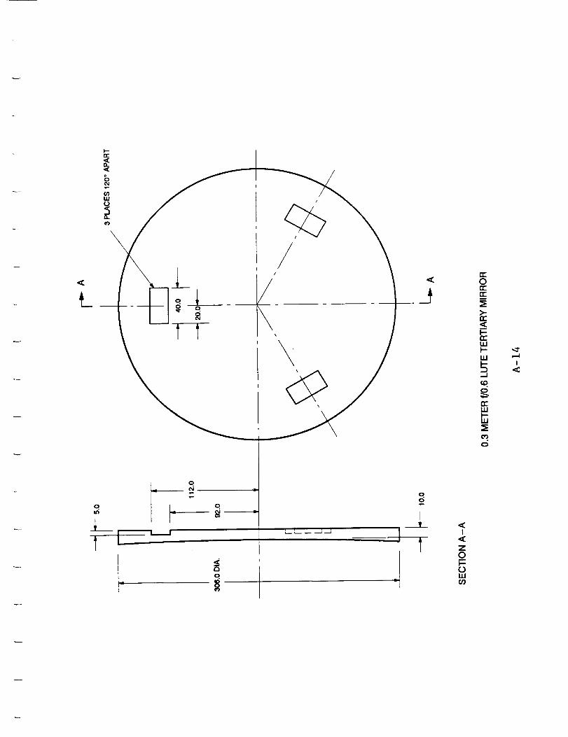
3.2 PRIMARY/TERTIARY MIRRORS
During our LUTE PM Study we tentatively concluded that an integral PM/TM de-
sign was preferable. Consultations with our optical fabrication personnel indicatedthat in fact the fabrication of this mirror is feasible.
3-3

HUGHES
Hughes Danbury Optical Systems, Inc.a subsidiary
PR DI$-0015
//
//II
\\
SMAMETERING
STRUCTURE
SECONDARYMIRROR
ASSEMBLY
ARTICULATEDSECONDARY
MIRROR
/
PRIMARYMIRRORBAFFLE
MENISCUSTERTIARY _MIRROR
\\
f
J
/
//
\\
\\
//
////
////
//
_ _" "_ ...// _- // 't
,-_/TELESCOPE _ _v_ _ _ _ __._._ .... _
MAIN BULKHEAD
TELESCOPE HEXAPOD ACTUATORS(REPRESENTATION ONLY)
TELESCOPEUGHT SHADE
SECONDARYMIRRORBAFFLE
PRIMARYMIRROR
APERTURESTOP
SINGLETAPER
PRIMARYMIRROR
ff
ARTEMIS PAYLOADINTERFACE
Figure 3-2.. Our Lute Telescope is Based on a 3 Mirror Optical Design and a Very AggressiveWeight Budget.
34
PRDI$-0015HUGHES
Hughes Danbury Optical Syzlema, Inc.
a subsidiary
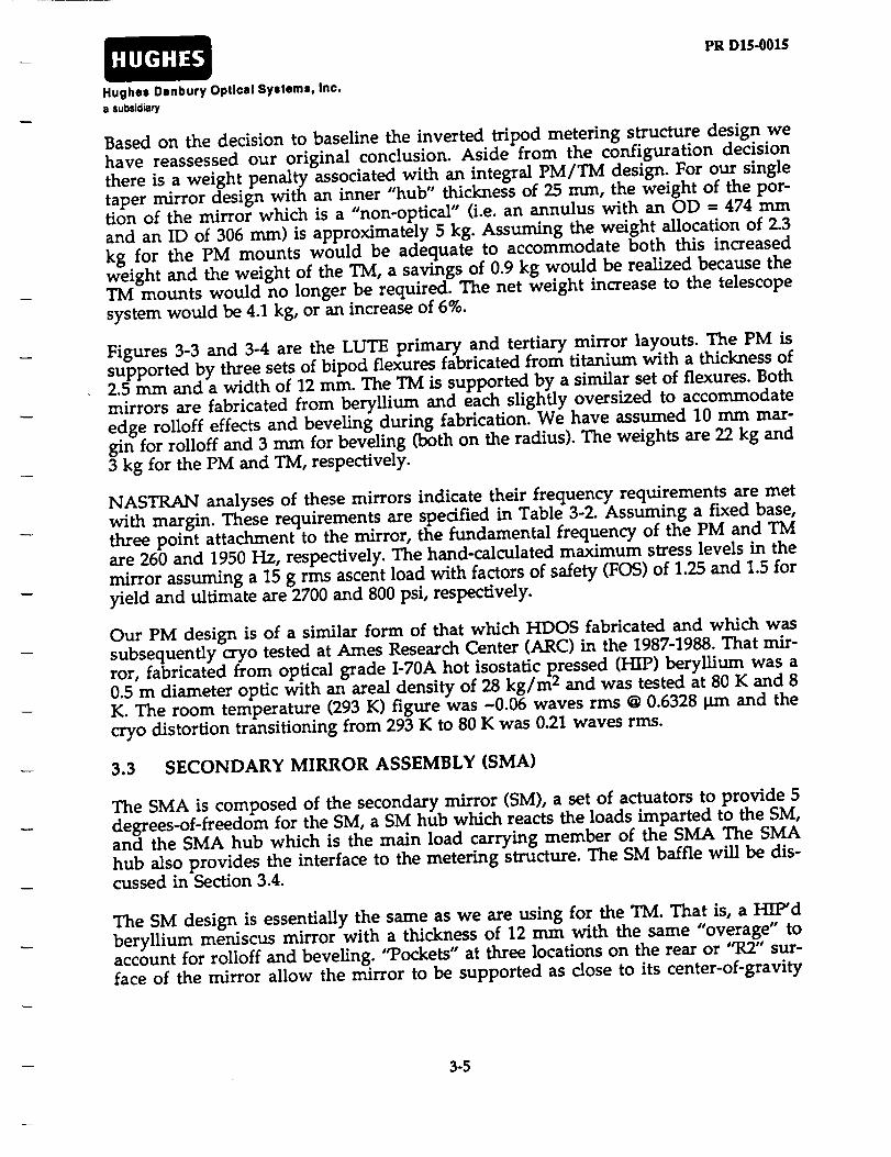
Based on the decision to baseline the inverted tripod metering structure design wehave reassessed our original conclusion. Aside from the configuration decisionthere is a weight penalty associated with an integral PM/TM design. For our singletaper mirror design with an inner "hub" thickness of 25 ram, the weight of the por-tion of the mirror which is a "non-optical" (i.e. an annulus with an OD = 474 mmand an ID of 306 mm) is approximately 5 kg. Assuming the weight allocation of 2.3kg for the PM mounts would be adequate to accommodate both this increasedweight and the weight of the TM, a savings of 0.9 kg would be realized because theTM mounts would no longer be required. The net weight increase to the telescopesystem would be 4.1 kg, or an increase of 6%.
Figures 3-3 and 3-4 are the LUTE primary and tertiary mirror layouts. The PM issupported by three sets of bipod flexures fabricated from titanium with a thickness of2.5 mm and a width of 12 ram. The TM is supported by a similar set of flexures. Bothmirrors are fabricated from beryllium and each slightly oversized to accommodateedge roUoff effects and beveling during fabrication. We have assumed 10 mm mar-gin for rolloff and 3 mm for beveling (both on the radius). The weights are 22 kg and3 kg for the PM and TM, respectively.
NASTRAN analyses of these mirrors indicatetheirfrequency requirements are metwith margin. These requirements are specifiedin Table 3-2.Assuming a fixed base,three point attachment to the mirror,the fundamental frequency of the PM and TM
are 260 and 1950 Hz, respectively.The hand-calculatedmaximum stresslevelsin themirror assuming a 15 g rrnsascentload with factorsof safety(FOS) of 1.25and 1.5foryieldand ultimateare 2700 and 800 psi,respectively.
Our PM design is of a similar form of that which HDOS fabricated and which wassubsequently cryo tested at Ames Research Center (ARC) in the 1987-1988. That mir-ror, fabricated from optical grade 1-70A hot isostatic p_ressed (HIP) beryllium was a0.5 m diameter optic with an areal density of 28 kg/m 2 and was tested at 80 K and 8K. The room temperature (293 K) figure was -0.06 waves rms @ 0.6328 _n and thecryo distortion transitioning from 293 K to 80 K was 0.21 waves rms.
3.3 SECONDARY MIRROR ASSEMBLY (SMA)
The SMA is composed of the secondary mirror (SM), a set of actuators to provide 5degrees-of-freedom for the SM, a SM hub which reacts the loads imparted to the SM,and the SMA hub which is the main load carrying member of the SMA The SMAhub also provides the interface to the metering structure. The SM baffle will be dis-cussed in Section 3.4.
The SM design is essentially the same as we are using for the TM. That is, a HIP'dberyllium meniscus mirror with a thickness of 12 nun with the same "overage" toaccount for rolloff and beveling. "Pockets" at three locations on the rear or "R2" sur-face of the mirror allow the mirror to be supported as close to its center-of-gravity
3-5

HUGHES
Hughes Danbury Optloxl Systems, Inc.s su_icl_u'y
PR D15-0015
i
w
,, o.
I
\\v_o.
-- qO
r¢-
o.O ,<
I<CZo
LU
Lo
M
.s.4:
,.I
1,1
o._q
tm
S
r:.
3-6

HUGHES
Hughes Danbury Optical Systems, inc.a subsidiary
PR D15-0015
L
o
±/
/
\
\
i q
t'q I.
t-.. t..-- ..--J -.a
O
O
O
I
I
ZoI:::
. I,,UOr)
3-7
HUGHES
Hughes Danbury Optical Systems, inc.
s subsid_ry
PR D15-0015
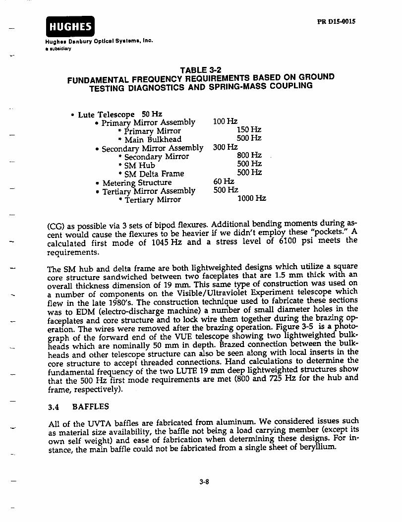
TABLE 3-2FUNDAMENTAL FREQUENCY REQUIREMENTS BASED ON GROUND
TESTING DIAGNOSTICS AND SPRING-MASS COUPLING
• Lute Telescope 50 Hz• Primary Mirror Assembly
* Primary Mirror* Main Bulkhead
e Secondary Mirror Assembly* Secondary Mirror* SM Hub* SM Delta Frame
• Metering Structure• Tertiary Mirror Assembly
* Tertiary Mirror
100 Hz150 Hz500 Hz
300 Hz800 Hz
500 Hz500 Hz
60 Hz500 Hz
1000 Hz
(CG) as possible via 3 sets of bipod flexures. Additional bending moments during as-cent would cause the flexures to be heavier if we didn't employ these "pockets." Acalculated first mode of 1045 Hz and a stress level of 6100 psi meets therequirements.
The SM hub and delta frame are both lightweighted designs which utilize a squarecore structure sandwiched between two faceplates that are 1.5 mm thick with anoverall thickness dimension of 19 mm. This same type of construction was used ona number of components on the Visible/Ultraviolet Experiment telescope whichflew in the late 1980's. The construction technique used to fabricate these sectionswas to EDM (electro-discharge machine) a number of small diameter holes in thefaceplates and core structure and to lock wire them together during the brazing op-eration. The wires were removed after the brazing operation. Figure 3-5 is a photo-graph of the forward end of the VUE telescope showing two lightweighted bulk-heads which are nominally 50 mm in depth. Brazed connection between the bulk-heads and other telescope structure can also be seen along with local inserts in thecore structure to accept threaded connections. Hand calculations to determine thefundamental frequency of the two LUTE 19 mm deep lightweighted structures showthat the 500 Hz first mode requirements are met (800 and 725 Hz for the hub andframe, respectively).
3.4 BAFFLES
All of the UVTA baffles are fabricated from aluminum. We considered issues such
as material size availability, the baffle not being a load carrying member (except itsown self weight) and ease of fabrication when determining these designs. For in-stance, the main baffle could not be fabricated from a single sheet of beryllium.
3-8
HUGHES
Hughes Danbury Optical Systems, Inc.
a subsidiary
BLAC_
3-9
PR D15-0015
ORIGINAL PAGE
A_ID WHITE PHOTOGRAPH ,-1
¢q
<m=
Lom
c--e=
&O
[-r,d
;>
,.=
¢=
S
¢/3
.2"I=
,4=
p,
t_
==r,j
Esm==m
>..=t_
I=
I,.
..=

PR DI$-O01SHUGHES
Hughes Danbury Optical Systems, Inc.
a subsidiary
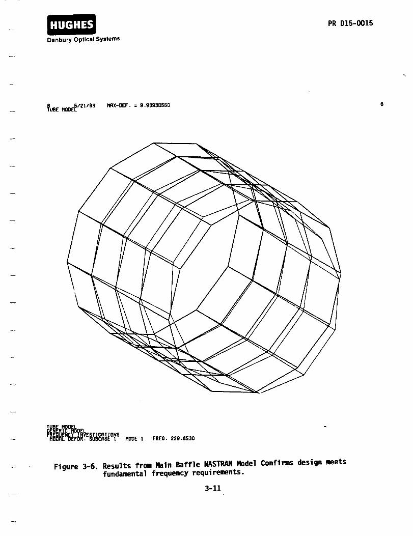
The main baffle is nominally 1120 mm in diameter and 960 mm in length. Its con-
struction is a ring-stiffened structure with a wall thickness of 0.4 mm. Internal vanes
which are 25 mm deep are attached to this shell and act as both structural stiffeners
and stray light control vanes. Figure 3-6 is the NASTRAN modal analysis of this
structure which shows a first bending mode frequency of 230 Hz and weight of 5.9
kg. This weight is slightly higher than the original estimate of 4.1 kg and is due to
the further definition of the packaging requirements of the SMA.
Both the SM baffles are of similar construction to that of the PM baffle. Aluminum
is again used for both SM baffles which are truncated cones with vanes located on
the OD and ID. These baffles are attached the SM delta frame through a series of
pinned and bolted joints. The combined weights of both of these structures is 2.1 kg.
The central baffle (primary baffle) has two functions. It's first function is to act as a
stray light control component. We again have kept it's shell thickness the same asall other LTVTA baffles. However this baffle also aids in the stiffening of the meter-
ing structure. In order to decrease the effective cantilevered length of the metering
structure and thereby increase its natural frequency, we've connected the central baf-
fle to not only the main bulkhead top faceplate but also the beryllium tubes which
form part of the metering structure. As will be discussed in the next section, this
"doses" the metering structure on its ID while a second stiffening shell, considered
part of the metering structure assembly, "doses" the structure on its OD.
3.5 METERING STRUCTURE ASSEMBLY
Our inverted tripod structure takes advantage of the annular region between the PM
ID and TM OD to package the metering structure. This structure is connected to the
main bulkhead via an interface flange which is pinned and bolted to the top face-
plate. Our current concept for this design is to utilize 6 beryllium tubes that are 34mm in diameter with a wall thickness of 2.5 mm. These six tubes extend from the
main bulkhead interface flange in a slightly canted orientation (i.e. the origin of the
term "inverted") to a point approximately 240 mm from the main bulkhead inter-face. Three of the six structural tube members are terminated at this location to min-
imize distortion at the image plane due to this obscuration. The three members that
are terminated are "capped" with three sections of an annular ring. These sections
are brazed to the top of the members and to the periphery of the three structural
members which continue up to the SMA. This adds significant rigidity to the struc-ture. To further add stiffness of this structure an outer shell is attached to all six tube
members. By designing this structure in this fashion the effective cantileveredlength of the metering structure is significantly reduced.
NASTRAN analysis of this structure has been completed. Assuming that the can-
tilevered length is approximately 560 mm (the distance from the termination of
three metering structure tube members to the SMA support location), and using the
SMA calculated weight estimate of 7.2 kg, our analysis shows the first bending
3-10
HUGHES
Danbury Optical Systems
PR D15-0015
I_LIBEMODE_/21/93 IIFiX-DEF. = 9.93930560
obIrREO• 229.8530
Figure 3-6. Results from I_in Baffle I_STRAN Model Confirms design meetsfundamental frequency requirements.
3-11

PR D15.0015HUGHES
Hughes Danbury OptloslSystems, Inc.s su_JclJaty
mode of the metering structure is 65 Hz. The first torsional mode of this structure is104 Hz. The 60 Hz derived requirement is satisfied with this design approach andtherefore we feel comfortable that ascent and lunar performance can be achieved.
The total weight of this structure is 2.2 kg which includes the weight of the 3 shortand long beryllium tubes, the 3 annular ring "caps", the main bulkhead interfaceflange, and the 240 mm long metering structure closure cylinder. The "caps" and theinterface flange are both 2.5 mm thick while the truncated cylinder is 1.3 mm thick.Hand stress analysis show that tube stress levels are low. A calculated stress of 9200psi in a tube is well within the nominal values for yield and ultimate failure criteriafor extruded beryllium structural shapes.
3.6 MAIN BULKHEAD
Our main bulkhead design is one of the major reasons why we feel that the 84 kgtelescope weight requirement is feasible. To develop this concept we combined thefact that the PM single taper design requires its mounts to be located near its centralhub and that the telescope main baffle must only be self supporting.
Lightweighting of this structure is evident. Minimization of weight is accomplishedthrough the use of lightening holes and cutouts. Shear panels, which "beam" theloads from the top to bottom faceplates and then transfer these loads to the telescopehexapod actuators utilize these techniques. Three plates connecting the six shearpanels have been designed to maintain structural stability while adding structuralstiffness to the main bulkhead. These plates also have been lightweighted via"cutouts". The telescope main baffle only requires connection to the lower face-plate/shear panel locations at six locations due to its low weight. Local "L" bracketsare used to make this connection through the OD of the main baffle. Where themain baffle is not connected to these six locations, non-load carrying secondarystructure is used to control contamination and reflections off the lunar lander
and/or surface. To facilitate PM and TM alignment, six local raised pads are locatedon the top faceplate of the main bulkhead. This allows tight tolerances to be main-tained over a relatively small area.
The bulkhead is fabricated from beryllium. There are 3 "field splices" of the largerfaceplate because of manufacturer limitations on maximum available size. Thesesplices occur directly over three of the shear panels. All main bulkhead plate thick-ness are nominally 2.5 ram. Faceplate, shear panels and plates are brazed together tomake a continuous, rigid, and deterministic structure. We used hand calculations toshow that a first mode of 870 Hz and a maximum stress level of 5200 psi suggeststhis design is robust. We believe that more detailed analysis would continue toshow this design meets its requirements.
3-12

PRD15-0015HUGHES
Hughee Danbury Optical Systems, Inc.
a subsidiary
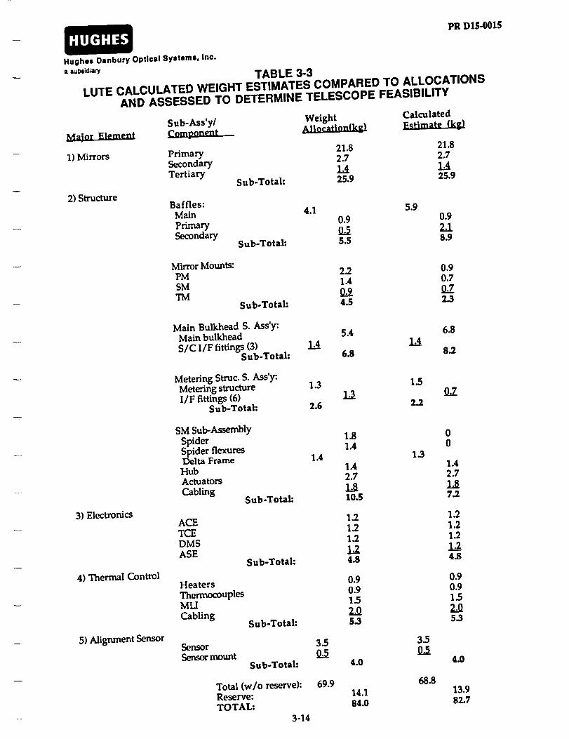
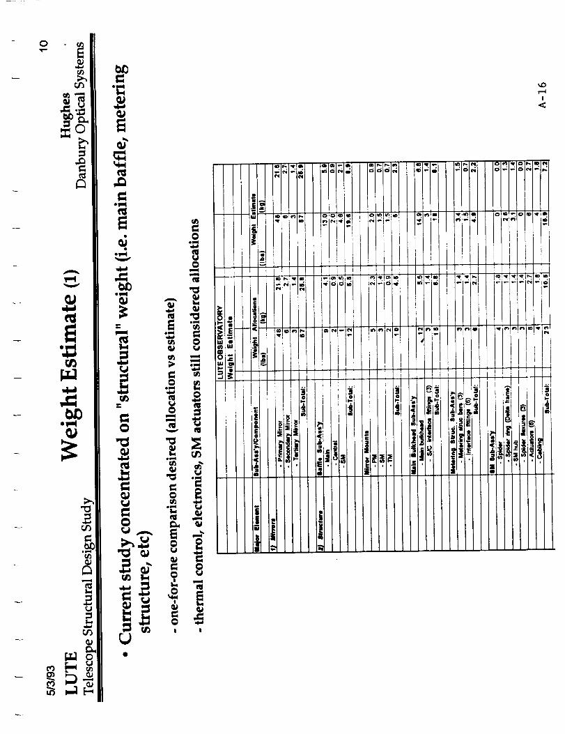
3.7 WEIGHT ESTIMATES
The UVTA telescope weight estimates for the HDOS strawman design is shown inTable 3-3. This weight estimate reflects the updates to the original design concept usein the PM Materials & Design Study in terms of the metering structure, main bulk-head, baffles, and SMA. No attempt was made to assess the original allocationsmade to the electronics, alignment sensor and thermal control.
We have concluded that the original "structural" weight allocations are reasonableand except for some redistribution of weight, our original estimates were reasonable.There appears to be no outstanding issues with respect to launch survivability ordynamic characteristics which would indicate that these estimates will significantlyincrease.
3-13
PRDIS-001$HUGHES
Hughe= Danbury Optical Syatama, Inc.
a =ubsidian/
TABLE 3-3LUTE CALCULATED WEIGHT ESTIMATES COMPARED TO ALLOCATIONS
AND ASSESSED TO DETERMINE TELESCOPE FEASIBILITY
2) Structure
Sub-Ass'y/ Weight Calculated_.sumte_(k_
Primary 21.8 21.8Secondary 2.7 2.7Tertiary 1.4 1.4
Sub-Total: 25.9 25.9
Baffles:Main 4.1 5.9
Primary 0.9 0.9Secondary 0.5 2.1
Sub-Total: 5.5 8.9
Mirror Mounts:PM 2.2 0.9SM 1.4 0.7TM O.9 0.7
Sub-Total: 4.5 2.3
Main Bulkhead S. Ass'y:Main bulkhead 5.4 6.8
SIC I/F fittings (3) 1.4 1.__44Sub-Total: 6.8 8.2
Metering Struc. S. Ass'y:Metering structure 1.3 1.5I/F fittings (6) 1.3
Sub-Total: 2.6 2.2O.7
3)Electronics
4) Thermal Control
5) Alignment Sensor
SM SubAssemblySpider 1.8 0Spider flexures 1.4 0Delta Frame 1.4 1.3
Hub 1.4 1.4Actuators 2.7 2.7
Cabling 1.8 1.8Sub-Total: 10.5 7.2
ACE 1.2 1.2TCE 1.2 1.2DMS 1.2 1.2
ASE 1.2 1.2Sub-Total: 4.8 4.8
Heaters 0.9 0.9Thermocouples 0.9 0.9MLI 13 13
Cabling 2.0 2.0Sub-Total: 5.3 5.3
Sensor 33 33Semormount 03 03
Sub-Total: 4.0 4.0
Total (w/o reserve): 69.9Reserve: 14.1TOTAL: 84.0
3-14
68.813.982.7

HUGHES
Hughes Danbury Optical Systems, Inc.a subsidiary
PR D15-0015
SECTION 4
PRIMARY-TO-SECONDARY MIRRORDESPACE PREDICTIONS
4.1 THERMALLY INDUCED
Early in the study we traded metering structure design options. Using the workcompleted and documented in the MSFC "LUTE Interim Report" with respect to theHubble Space Telescope (HST) type metering truss design, we investigated two addi-tional types of structures. The first is a metering bar design approach where low coef-ficient-of-thermal expansion (CTE) material (i.e. fused quartz) is used to maintainthe spacing between the primary and secondary mirrors in the presence of bulktemperature changes. This design approach is beneficial when considering a tele-scope design whose bulk temperature change, about some mean, is relatively small.This design approach possibly allows the elimination of the secondary mirror adjustmechanism thereby saving weight and reducing telescope complexity. Our "LUTEPrimary Mirror Materials and Design Study Report", PR D15-0013A, discusses addi-tional aspects of this design and includes a schematic of how this design approachcould be implemented.
Based on the weight allocation of 84 kg for the telescope assembly, we concluded thatthe material of choice for LUTE is beryllium. This being the case, we calculated theamount of PM-to-SM despace if we assumed an all beryllium telescope and a tele-scope assembly temperature of 293 K (i.e. room temperature). These calculations alsoassumed that the mean temperature of the operational LUTE is 160 K with a rangeof temperature about this mean of + 100 K. We used the data included in PR D15-0013A to account for CTE as a function of temperature. The calculations are as fol-lows using the primary mirror as the reference.
• Beryllium structure:
(AL) mean-to-cold = {(AL) for 160K - 60 K} = 130 IJ.rn
(AL) mean-to-hot = {(AL) for 160K - 260 K} = 487
Therefore for beryllium, the worst case is for the mean-to-hot case when the PM-to-SM spacing "grows" by 487 _m. However for a telescope which uses the same mate-rial throughout its optical "train", the telescope is athermalized. What is implies isthat even though the spacing has changes by 487 _Lrn, the radius of curvature of theprimary and secondary mirror has changes by the same ratio. Therefore by defini-tion, the wavefront error is identically zero (of course due to material inhomo-geneities it is not identically zero.)
4-1

PRD15-0015HUGHES
Hughes Danbury Optical Systems, Inc.a subsid_
When we considered the metering bar approach several issues were immediatelyevident. First was that the temperature "swings" of the telescope is measured in"lO0's" of degrees not "a few degrees" which we typically would anticipate whenconsidering a metering bar design and secondly, the optics are beryllium, not themore conventional "glass" optics where radius of curvature matching with "glass"metering rods could be accomplished. As a example of why a metering rod approachis not appropriate for LUTE, we continue similar calculations as shown above.
• Fused quartz metering rods:
(AL) mean-to-cold = {(AL) for 160K - 60 K} = 36 _,n
(AL) mean-to-hot = {(AL)for 160K -260 K} = 13 pan
These calculations show that even though the relative motion between the mirrorsis much less, this motion obviously does not match the corresponding radius ofcurvature changes that the beryllium mirrors undergo. If the mirrors were fabri-cated from fused quartz (it is our opinion that this could only happen if the tele-scope weight allocation of 84 kg was significantly relaxed), then an assessment of thewavefront errors caused by the uncertainty of these values (remember material in-homogeneities, etc.) would need to be undertaken.
We made similar calculations to assess the impact of axial (i.e. along the telescope'slength) temperature gradients on telescope performance. In this case, a telescopewhich uses the same material for both the structure and the optics does not neces-sarily enjoy any benefit when considering thermally induced deformations. This isshown in the Table 4-1 were we calculated allowable telescope axial temperaturegradients to meet the PM-to-SM alignment requirement of 0.0212 waves rms (@0.6328 p.m) due to lunar day-to-night changes as shown in PR D15-0013A. These re-sults show that for axial temperature gradients, the all beryllium telescope will re-quire a focus mechanism based on our understanding of the thermal analysis resultspresented in the MSFC report which suggests that the telescope axial gradients willbe in excess of the 0.3K allowed. Conversely, a large benefit would be realized if thefused quartz metering bar design was chosen based on the allowable axial gradient.However as discussed, the PM-to-SM separation due to bulk temperature resultsdearly shows that LUTE is not suitable for the metering bar approach.
We did not conduct a LUTE-specific optical sensitivity analysis. In lieu of this wescaled sensitivity results from a similar three mirror telescope design. These sensi-tivities are shown in Table 4-2. We recommend that further work be undertaken to
determine the specific optical sensitivities and that further analysis on PM-to-SMdecenter (i.e. motion perpendicular to the optical axis) and relative flits between thetwo elements be considered when bounding the allowable temperature gradients.From the results presented above we believe our inverted tripod design approachfor the LUTE metering structure is appropriate.
4-2

HUGHES PR D15-0015
Hughes Danbury Opticsl Systems, Inc.
i subsidiary
TABLE 4-1A MATERIAL WITH A LOW CTE OVER THE ENTIRE OPERATING TEMPERATURE
RANGE IS PREFERRED SO THAT WAVEFRONT DISTORTIONS CAUSED
BY TELESCOPE AXIAL TEMPERATURE GRADIENTS ARE MINIMIZED
Operating
Temp (K)
Allowable Axial Temp Gradient (K)
Beryllium Fused Quartz
260 0.3 30
160 m
60 1.5 4
TABLE 4-2SCALED RESULTS FROM A SIMILAR OPTICAL DESIGN WERE USED
TO CALCULATE ALLOWABLE TELESCOPE AXIALTEMPERATURE GRADIENTS
Secondary MirrorMotion
Wavefront Distortion Sensitivity(waves rms @ 0.6328 Rm)
• 1 _rn despace 0.02• 1 pan decenter 0.004• I arcsec tilt 0.017
4.2 SECONDARY MIRROR FOCUS MECHANISM RANGE
To assess the precise amount of despace motion which the telescope must accom-modate, a number of analyses and/or tests must first be conducted. These include:
a) LUTE-specific wavefront error sensitivity analyses
b) Metering structure material _L/L characteristics:
1) uncertainty
2) repeatability
3) homogeneity
c) Assembly misalignments
d) Launch induced misalignment
e) Exact operational bulk and temperature gradients
0 5/6's g release
4-3

PR DI$-0015HUGHES
Hughes Danbury Optical Systems, Inc.
a subsidiary
We have attempted to begin this assessment assuming an all beryllium telescopewhich is aligned and tested in lg at 293 K. These results are shown in Table 4-3.These values should be considered as a preliminary assessment which will need tobe updated as the LUTE specific "architecture" in terms of structural form and mate-rial choice is baselined.
One must apply considerable margin to account for the error sources shown in Table4-3 which are "tbd." We believe the LUTE secondary mirror mechanism should
have a minimum despace range of :t:l mm. For reference, the HST SM mechanismhas a despace range of approximately :t=3mm.
TABLE 4-3IDENTIFICATION OF DESPACE ERROR SOURCES HAVE BEEN MADE.
ADDITIONAL ANALYSES AND TEST DATA REQUIRED TO FULLYQUANTIFY THESE EFFECTS ON OPTICAL PERFORMANCE
Despace Error Estimated Despace Equiv. DefocusSource Motion (}_m) Error (waves-rms)
• Initial misalignment• 5/6 g release uncertainty• Launch residual
• Bulk temp. effects- 260 K to 160 K- 160 K to 60 K
• Temp. gradients- PM, SM, TM- Metering structure
• AL/L effects- PM, SM, TM- Metering structure
0.4 0.0080.3 0.006tbd tbd
490 0130 0
tbdtbd
tbdtbd
tbdtbd
ttxitbd
4-4

HUGHES
Hughes Danbury Optical Systems, Inc.a subsicl_ry
PR D15.0015
SECTION 5
MECHANICAL LAYOUTS
5.1 OVERALL UTVA
Our recommended LUTE telescope design described in detail in Section 3 is based on
a set of requirements which dictates that the telescope have diffraction limited per-formance while at the same time be light weight and structurally stiff. Shown earlier
in Figure 3-2, the isometric view of our telescope highlights the major telescope
components which we believe will meet this set of requirements.
Figure 5-1 is an "exploded" view of the telescope providing further definition of its
components, the material which the component is fabricated from, insight into the
fabrication technique which we recommend for its construction, and other pertinent
information to help in the overall understanding of form and function. Figures 5-2
and 5-3 provide the more classical "side" and "top" views of the telescope. Thesefigures are "to scale" to show that all components _are consistent with volume con-
straints and that no interferences occur which could jeopardize the overall telescopearchitecture.
5-1

PR D15-0015HUGHES
Danbury Optical Systems
SECONDARY MIRROR BAFFLES
- _INDER WNANES- ATTACHED TO SECONDARY MIRROR
DELTAFRAME
- N.UM_U_
PRIMARY MIRROR
- 1.o M f/IO- SINGLE TAPER DESIGN- $ _ OF BiPOO FLEXURES
- _,m s
- HIDT.DBER_I.L_
Figure 5-I. The "Exploded" View of the Lute Telescope Provide Insight into
Assembly Sequences along with Material and Fabrication Techniques.
5-2

HUGHES
Hughes Danbury Optlosl Systems, Inc.a subsidiary
PR D15-0015
BB
A
1120
Figure 5-2. "Side" View of the Lute Telescope.
5-3

PR D15-0015HUGHES
Danbury Optical Systems
lOOO
SECTION B- B
S60
510
SCALE IN mr.
I'"'""'1 ' J ' I ' I ' ISECTIONA-A o ,® == =_ ,m =_
Figure 5-3. "Top Views of the Lute Telescope Sections "A-A" and "B-B" Highl|ghtsthe Rain Bulkhead and Primry/Tertiary 14irrors, Respectively.
5-4
HUGHES
Hughes Danbury Optical Systems, Inc.a subsid_ry
PR D15-0015
SECTION 6
RECOMMENDATIONS
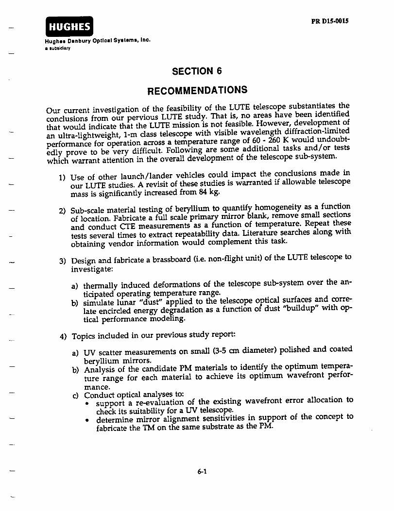
Our current investigation of the feasibility of the LUTE telescope substantiates the
conclusions from our pervious LUTE study. That is, no areas have been identifiedthat would indicate that the LUTE mission is not feasible. However, development of
an ultra-lightweight, 1-m class telescope with visible wavelength diffraction-limited
performance for operation across a temperature range of 60 - 260 K would undoubt-
edly prove to be very difficult. Following are some additional tasks and/or testswhich warrant attention in the overall development of the telescope sub-system.
1) Use of other launch/lander vehicles could impact the conclusions made in
our LUTE studies. A revisit of these studies is warranted if allowable telescope
mass is significantly increased from 84 kg.
2) Sub-scale material testing of beryllium to quantify homogeneity as a function
of location. Fabricate a full scale primary mirror blank, remove small sections
and conduct CTE measurements as a function of temperature. Repeat these
tests several times to extract repeatability data. Literature searches along with
obtaining vendor information would complement this task.
3) Design and fabricate a brassboard (i.e. non-flight unit) of the LUTE telescope to
investigate:
a) thermally induced deformations of the telescope sub-system over the an-tidpated operating temperature range.
b) simulate lunar "dust" applied to the telescope optical surfaces and corre-
late encircled energy degradation as a function of dust "buildup" with op-tical performance modeling.
4) Topics included in our previous study report:
a) UV scatter measurements on small (3-5 cm diameter) polished and coated
beryllium mirrors.
b) Analysis of the candidate PM materials to identify the optimum tempera-
ture range for each material to achieve its optimum wavefront perfor-mance.
c) Conduct optical analyses to:
• support a re-evaluation of the existing wavefront error allocation tocheck its suitability for a I.W telescope.
• determine mirror alignment sensitivities in support of the concept tofabricate the TM on the same substrate as the PM.
6-1

HUGHES
Hughes Danbury Optical Systems, Inc.a subsidiary
PR D15-0015
APPENDIX A
LUTE VIEWGRAPHS FROM 4 MAY 1993 TECHNICAL TELECON
A-i

L
Tl
QJ
¢J')
¢/')
_J
-l-J
r_
e_I-I
E-
QJ
0owl
e_
1-Ie_
0r_
v-,,,l
w,-Ie_r_
oIEl
r_
QJ
e_
!
o
!

f
• _= _= _--_/
D
I
<

I

_mo
i
Cr_
_ m
Ii
!

°
e_
,-.o
!

,¢

SECONDARYMIRROR
ASSEMBLY
ARTICULATEDSECONDARY
MIRROR
TELESCOPEUGHT SHADE
SMAMETERING
STRUCTURE
PRIMARYMIRRORBAFFLE
I SECONDARYMIRRORBAFFLE
PRIMARYMIRROR
APERTURESTOP
//
//
/I
I\\\
\\
\
MENISCUSTERTIARY
MIRROR
/
/
//
\\
\
TELESCOPEMAIN BULKHEAD
\\
//
////
////
/\\\ /I \
TELESCOPE HEXAPOD ACTUATORS(REPRESENTATION ONLY)
SINGLETAPER
PRIMARYMIRROR
\%
"< ....\
iI
ARTEMIS PAYLOADINTERFACE(1.82M DIA)
//
//
\
I//
//
A-9

SECONOA.Y.,..O. \- SUPPORTS SECONDARY MIRROR ASSEMBLY
BRAZED BERYLLIUM
- INTERFACE TO METI=RING S_:_UCTURE
SECONDARY MIRROR BAFFLES J____l-- C_I.INDER W/VANES
- ATTACHED TO SECOM_ARY MIRROR I
DELTA FRAME I
- ALUMINUM
I
I
METERING STRUCTURE:PRIMARY BAFFLE
- INTEGRAL CONSTRUCTION
- ADOED STIFFNESS W/O
I
i!iiiiiiiiiiiiiliiiii!iiiiiiiiiiiiiiii_i_
SECONDARY MIRROR HUB
- ARTICULATED ViA SECONDARY
MIRROR ACTUATORS
- BRAZED BERYLLIUM
SECONDARY MIRROR
MENISCUS CONS11_
- SUPPORTED AT C.G VIA FLEXURES
- HIP_D BERYLLIUM
TELESCOPE MAIN BAFFLE
- NON4_OAD CARRYING
- ISO- GRID OR CONVENTIONAL
- ATTACHED TO MAiN BULKHEAD VtASiX FrTTINGS
- ALUMINUM
A-IO

B
A
m
m
m
m
m
m
-[_ i___i!ii_iiii
u
w
N
B
m
, r :i!!'!! I J iiii
11 J[[ JIi::_ | I r i :i
,,J J '::_i
' I00o" - 1120
A
96O
SCALE IN mm
V'""l ' I ' I ' I ' I0 100 2OO 300 40O 5OO
A-11

\
28O(C.A.)
SECTION B-B
180
110
TtOO0(C.A.)
510
\\\\
SECTION A-A
SCALE IN mm
0 100 200 300 400 500
A-12

0
0,I
O
n-Oi.r
>-It-
n-Q_LIJ _t-- ,-i
._I c_
O.
rr
c_o.
o.
±/
o.
j
o.
q0
I
Zo_
0u.Iffl
0
I--er"LLI
W
5
erW
0
!

!
A
_ ._
) .i_ 8
im¢!

c_
r_
il
!

c_qlrm
aO
_t
!

U
Z
A A A A
O O
_,_, ,, ,
I
,<

!
Recommended