8/8/2019 Logic Motion Safety v041
http://slidepdf.com/reader/full/logic-motion-safety-v041 1/15
PLCopenfor efficiency in automation
Total number of pages: 15
Technical Paper
PLCopen Technical Committees 2 & 5
Logic, Motion, Safety
PLCopen Working Document, Version 0.41. Released as is.
DISCLAIMER OF WARANTIES
THIS DOCUMENT IS PROVIDED ON AN “AS IS” BASIS AND MAY BE SUBJECT TO
FUTURE ADDITIONS, MODIFICATIONS, OR CORRECTIONS. PLCOPEN HEREBYDISCLAIMS ALL WARRANTIES OF ANY KIND, EXPRESS OR IMPLIED, INCLUDING
ANY WARRANTY OF MERCHANTABILITY OR FITNESS FOR A PARTICULAR PURPOSE,
FOR THIS DOCUMENT. IN NO EVENT WILL PLCOPEN BE RESPONSIBLE FOR ANY
LOSS OR DAMAGE ARISING OUT OR RESULTING FROM ANY DEFECT, ERROR OR
OMISSION IN THIS DOCUMENT OR FROM ANYONE’S USE OF OR RELIANCE ON THIS
DOCUMENT.
Copyright © 2007 .. 2008 by PLCopen. All rights reserved.
Date: April 17, 2008
8/8/2019 Logic Motion Safety v041
http://slidepdf.com/reader/full/logic-motion-safety-v041 2/15
PLCopenfor efficiency in automation
TC2 & TC5 © PLCopen (2007, 2008)
Logic, Motion, and Safety April 17, 2008 page 2/15
The following paper
Logic, Motion, Safety
is an official PLCopen document.
It summarises the results of the Technical Committees 2 – Functions and 5 – Safety during several
meetings, and containing contributions of all its members.
Name Company
Klas Hellmann Phoenix Contact
Jochen Ost Bosch Rexroth
Candido Ferrio Omron Yaskawa Motion Control
Josep Lario Omron Yaskawa Motion ControlArmin Wenigenrath Schneider Electric
Willi Gagsteiger Siemens
Bernard Mislewicz Siemens
Roland Schaumburg Danfoss
Frank Bauder Omron Europe
Jürgen Hipp ISG
Wolfgang Fien Berger Lahr
Harald Buchgeher KEBA
Stefan Pollmeier ESR
Christian Fügner Baumüller
Eelco van der Wal PLCopen
Change Status List:
Version
number
Date Change comment
V 0.1 June 06, 2007First release after kick-off meeting on March 15, and pré work
done by Klas Hellmann and Eelco van der Wal in June 2007.
V 0.2 June 12, 2007 As result of the meeting in Neuremberg.
V 0.3 July 11, 2007 As result of the meeting in NiederschopfheimV 0.4 Sept. 28, 2007 As result of the meeting in Neuremberg
V. 041 April 17, 2008First released version with minor correctional changes.
Incomplete SFC example removed
8/8/2019 Logic Motion Safety v041
http://slidepdf.com/reader/full/logic-motion-safety-v041 3/15
PLCopenfor efficiency in automation
TC2 & TC5 © PLCopen (2007, 2008)
Logic, Motion, and Safety April 17, 2008 page 3/15
Contents
1 COMBINING LOGIC, MOTION AND SAFETY – AN INTEGRAL APPROACH...........4
1.1. GOAL.......................................................................................................................................4
1.2. DEFINITIONS............................................................................................................................4
1.3. REFERENCES............................................................................................................................4
1.4. OUTLINE ..................................................................................................................................4
2 INTRODUCTION.......................................................................................................................5
2.1. MOTION AND SAFETY STATE DIAGRAMS ..................................................................................5
2.2. SAFETY REACTIONS AND CONDITIONS .....................................................................................5
3 MACHINE EXAMPLE 1 ...........................................................................................................6
4 MACHINE EXAMPLE 2 .........................................................................................................11
4.1. INTRODUCTION ......................................................................................................................11
4.2. PROGRAM EXAMPLE ..............................................................................................................12
4.3. STATE DIAGRAM EXPLANATION ............................................................................................15
8/8/2019 Logic Motion Safety v041
http://slidepdf.com/reader/full/logic-motion-safety-v041 4/15
PLCopenfor efficiency in automation
TC2 & TC5 © PLCopen (2007, 2008)
Logic, Motion, and Safety April 17, 2008 page 4/15
1 Combining Logic, Motion and Safety – an integral approach
1.1. Goal
The organization PLCopen published several technical documents in areas like motion control and
safety, besides the IEC 61131-3 standard focussed to the logic.
With the merge of these different technologies, logic, motion and safety, on one environment, a
need for examples of these combinations arose.
This document provides some of these examples. As such it adds to other PLCopen documents, like
Motion Control Part 3 – User Guidelines, as created within TC2 – Functions, or Safety Part 2 –
User Guidelines, as created within TC5 – Safety. In addition, results from other organizations are
used, like OMAC.
The combination of logic, motion and safety best can be done via a structured approach. Thisdocument provides guidance for such an approach, although other approaches are of course
possible. All provided solutions are supplied as example only to show the principal operation. and
not tested. Also, they can be solved in different ways, and the way presented does not have to be the
best one for your particular applications.
1.2. Definitions
Logic as used here is in the context of the IEC 61131-3 standard on programming languages.
Motion control is the movement of a single axis / motor, as well as synchronized action of several
(servo) motors, as specified by PLCopen Technical Committee 2 – Functions.
Safety in this document is the machine safety focused to allowing operating personell to work
safely, especially as defined in the PLCopen TC5 Safety specifications Part 1 and Part 2.
1.3. References
IEC 61131-3 – Part 3 of the IEC (International Electrotechnical Commission) 61131 standard,
focused to the programming languages for programmable logical controllers. Check www.iec.org
for more information.
PLCopen Motion Control – the suite of PLCopen specifications dedicated to motion control as
published on the PLCopen website. Currently consisting of 5 parts, including Part 3 – User
Guidelines. Check www.plcopen.org for more information under TC2.PLCopen Safety - the suite of PLCopen specifications dedicated to safety as published on the
PLCopen website. Currently consisting of 2 parts, including Part 2 – User Guidelines. Check
www.plcopen.org for more information under TC5.
1.4. Outline
This document contains two examples showing how to combine the PLCopen motion and safety
specifications in applications. If more examples become available, an update can be done.
8/8/2019 Logic Motion Safety v041
http://slidepdf.com/reader/full/logic-motion-safety-v041 5/15
PLCopenfor efficiency in automation
TC2 & TC5 © PLCopen (2007, 2008)
Logic, Motion, and Safety April 17, 2008 page 5/15
2 Introduction
Within the application program one can identify 2 parts:
1. Functional application – the program section that deals with the non-safety section. It
contains the logic and motion functionalities.
2. Safety application – the program section that deals with the safety application
Both parts exchange data to contol the overall process. The safety part basically enables safety
relevant action. The functional application however needs to control the process within the
monitored limits. (e.g. to stop drives in case of an ermergency stop).
2.1. Motion and safety state diagrams
There are state diagrams defined in both the Motion Control specifications, as part of the functional
application, and the Safety specification. These state diagrams reflect the state of the device. These
two state diagrams are separate implemenations, have little effect on each other, and are normally
used in parallel. The safety application can effect the functional application, and so the motion
control state diagram per axis or per group, especially if a safety conditionis valid.
2.2. Safety reactions and conditions
The safety application supports two tasks:
• Safety reaction – resulting in a safe state as quick as possible after certain monitored
conditions are not met (e.g. activating the emergency stop button or blocking a light
curtain)).
• Safety condition – this have to ensure a safe state before the action can be done (e.g.
unlocking a guard to enter the hazardous area. The precondition is that the area is safe (no
movement)). The functional application has to take care that it fulfills these requirements
(like safely limited speed).
Note: in case of a fail safe function, either of the safety application itself or a safe actor, the drive
will perform a fail safe reaction and will not perform any motion related actions anymore. This fail
safe reaction will be reflected (in the end) in the axis state diagram as an error.
8/8/2019 Logic Motion Safety v041
http://slidepdf.com/reader/full/logic-motion-safety-v041 6/15
PLCopenfor efficiency in automation
TC2 & TC5 © PLCopen (2007, 2008)
Logic, Motion, and Safety April 17, 2008 page 6/15
3 Machine example 1
Description of the safety requirementsThis example describes a machine with two electric drive systems within a working area where an
operator needs access to e.g. for process diagnosis, set-up activities or to clear a material jam.
The access to the working area is provided by an interlocking guard with guard locking. The
locking is required due to the fact that the operator could get access to the hazardous area before a
stop of the drive system is be performed completely.
In emergency situation the drive systems needs to be stopped in accordance with stop category 1
(EN60204).
A mode selector is used to switch the machine between automatic and set-up mode.
Within the set-up mode the guard door can be opened and the drive systems enabled to move with a
safely limited speed by using an enabling device.
The emergency stop (via SF_EmergencyStop) acts superimposed to all other safety functions and
puts the drive systems into a safe standstill (via SF_SafeStop1) in accordance with stop category 1
of EN60204-1.
After an emergency stop, the restart of the machine is only possible after the emergency button is
released and a reset signal is given (via SF_EmergencyStop)
The (normal) operation of the machine is only possible within the automatic mode (via
SF_ModeSelector) and the guard door closed (via SF_GuardMonitoring) and locked (via
SF_GuardLocking).
The guard door lock can be released within the set-up mode (via SF_ModeSelector) or after an
emergency stop (via SF_EmergencyStop) as soon as the drive systems are performing a safe
standstill (via SF_SafelyLimitedSpeed or SF_SafeStop1)
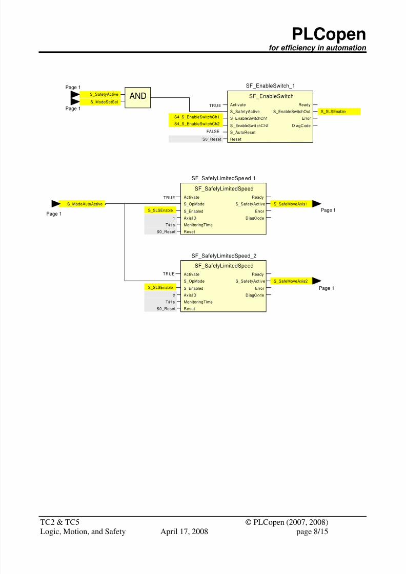
In the set-up mode (via SF_ModeSelector) the drive systems can be switched with the enabling
device (via SF_EnableSwitch) into a mode where movement with safely limited speed is allowed
(via SF_SafelyLimitedSpeed). The drive system can be moved by the motion controller via the
standard command values. The drive itself has to guarantee safely that the speed limit gets not
exceeded. (Note: If the motion control command values are greater than the parameterized limit the
drive system performs a fail-safe reaction independently.)
Without an enable signal (SF_EnableSwitch) the drive system stays in a safe standstill mode, where
the speed gets monitored to be zero (SF_SafelyLimitedSpeed) as long set-up mode is selected.
(Note: In this case the SF_SafelyLimitedSpeed FB puts the drive into a safe operational stop in
accordance with stop category 2 (EN60204) and acts like the SF_SafeStop2 FB)
There are only two operation modes regarding safety. In Automatic mode no safety functions have
to be active. If this mode is not selected, safety has to be ensured. The drive FBs differentiate only
between a safe and a non-safe (operation) mode.
If a non-automatic mode is selected and the enable switch is not activated theSF_SafelyLimitedSpeed acts as a SF_SafeStop2.
8/8/2019 Logic Motion Safety v041
http://slidepdf.com/reader/full/logic-motion-safety-v041 7/15
PLCopenfor efficiency in automation
TC2 & TC5 © PLCopen (2007, 2008)
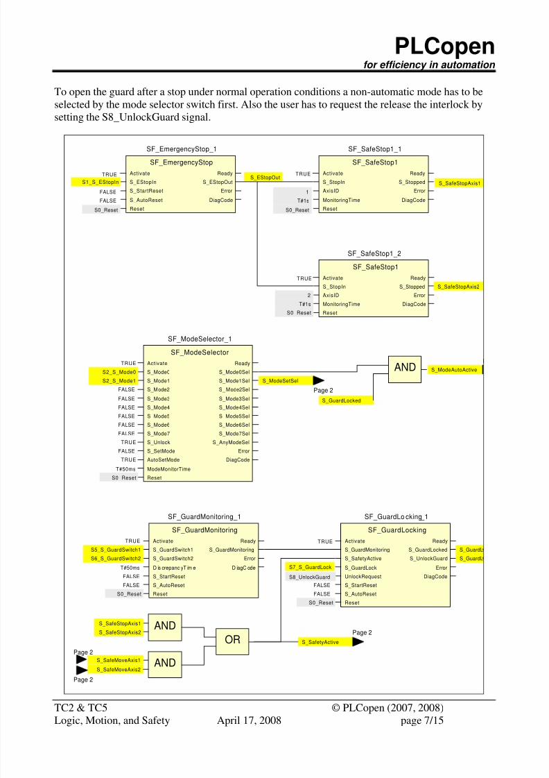
To open the guard after a stop under normal operation conditions a non-automatic mode has to be
selected by the mode selector switch first. Also the user has to request the release the interlock by
setting the S8_UnlockGuard signal.
Activate
S_EStopIn
Ready
S_EStopOut
SF_EmergencyStop
SF_EmergencyStop_1
S_StartReset
S_AutoReset
Error
DiagCode
ResetS0_Reset
TRUE
TRUE
S1_S_EStopIn
Page 2
Activate
S_StopIn
Ready
S_Stopped
SF_SafeStop1
SF_SafeStop1_1
AxisID
MonitoringTime
Error
DiagCode
ResetS0_Reset
T#1s
1
S_SafeStopAxis1
Activate
S_Mode0
Ready
S_Mode0Sel
SF_ModeSelector
SF_ModeSelector_1
S_Mode1
S_Mode2 S_ Mode2Sel
S_Mode3Sel
S_Mode5
S_Mode6
S_Unlock
AutoSetMode
ModeMonitorTime
S_Mode1Sel
S_SetMode
S_Mode7
S_Mode3
S_Mode4
Reset
S_Mode4SelS_Mode5Sel
S_Mode7Sel
S_AnyModeSel
S_Mode6Sel
Error
DiagCode
S2_S_Mode0
S2_S_Mode1
FALSE
FALSE
TRUE
S0_Reset
T#50ms
S_ModeAutoActive
S_ModeSetSel
TRUE
FALSE
FALSE
Activate
S_StopIn
Ready
S_Stopped
SF_SafeStop1
SF_SafeStop1_2
AxisID
MonitoringTime
Error
DiagCode
ResetS0_Reset
T#1s
2
S_SafeStopAxis2
AND
Activate
S_GuardSwitch1
Ready
S_GuardMonitoring
SF_GuardMonitoring
SF_GuardMonitoring_1
S_GuardSwitch2
D is crepanc yT im e D iagC ode
S_StartReset
S_AutoReset
Reset
Error
TRUE
S5_S_GuardSwitch1
S6_S_GuardSwitch2
T#50ms
FALSE
FALSE
S0_Reset
Activate
S_GuardMonitoring
Ready
S_GuardLocked
SF_GuardLocking
SF_GuardLo cking_1
S_SafetyActive
S_GuardLock Error
DiagCode
S_AutoReset
Reset
S_UnlockGuard
UnlockRequest
S_StartReset
S_GuardL
S7_S_GuardLock
S8_UnlockGuard
FALSE
S0_Reset
FALSE
S_SafeStopAxis1
S_SafeStopAxis2
ANDS_SafeMoveAxis1
S_SafeMoveAxis2
ORPage 2
Page 2
S_SafetyActive
S_GuardL
AND
S_GuardLocked
FALSE
FALSEFALSE
FALSE
FALSE
TRUE
TRUE
TRUE
Page 2
S_EStopOut
Logic, Motion, and Safety April 17, 2008 page 7/15
8/8/2019 Logic Motion Safety v041
http://slidepdf.com/reader/full/logic-motion-safety-v041 8/15
PLCopenfor efficiency in automation
TC2 & TC5 © PLCopen (2007, 2008)
Activate
S_SafetyActive
Ready
S_EnableSwitchOut
SF_EnableSwitch
SF_EnableSwitch_1
S_EnableSwitchCh1
S _EnableSw it chC h2 D iagC ode
S_AutoReset
Reset
ErrorS4_S_EnableSwitchCh1
S4_S_EnableSwitchCh2
TRUE
FALSE
S0_Reset
Activate
S_OpMode
Ready
S_SafetyActive
SF_SafelyLimitedSpeed
SF_SafelyLimitedSpe ed_1
S_Enabled
AxisID DiagCode
MonitoringTime
Reset
Error
S0_Reset
T#1s
1
S_SafeMoveAxis1
Activate
S_OpMode
Ready
S_SafetyActive
SF_SafelyLimitedSpeed
SF_SafelyLimitedSpeed_2
S_Enabled
AxisID DiagCode
MonitoringTime
Reset
Error
S0_Reset
T#1s
2
S_SafeMoveAxis2
S_SLSEnable
S_SLSEnable
S_SLSEnable
S_SafetyActive
Page 1
S_ModeSetSel
Page 1AND
S_ModeAutoActive
Page 1Page 1
Page 1
TRUE
TRUE
Logic, Motion, and Safety April 17, 2008 page 8/15
8/8/2019 Logic Motion Safety v041
http://slidepdf.com/reader/full/logic-motion-safety-v041 9/15
PLCopenfor efficiency in automation
TC2 & TC5 © PLCopen (2007, 2008)
Safe_Velocity1
JogAxis1
Safe_Velocity2
Axis2
Axis
Execute
Axis
Done
MC_MoveVelocity
JogAxis1
Position
Velocity Active
CommandAborted
Jerk
Direction
Busy
Buffermode
Acceleration
Deceleration Error
ErrorID
Axis
Execute
Axis
Done
MC_MoveVelocity
JogAxis2
Position
Velocity Active
CommandAborted
Jerk
Direction
Busy
Buffermode
Acceleration
Deceleration Error
ErrorID
ANDS_SLSEnable
Axis
Execute
Axis
Done
MC_Halt
NormalHaltAxis1
Deceleration
Active
CommandAborted
Busy
Buffermode
Jerk
Error
ErrorID
NOT
Aborting
Axis1
ANDS_SetModeSel
Axis
Execute
Axis
Done
MC_Halt
NormalHaltAxis2
Deceleration
Active
CommandAborted
Busy
Buffermode
Jerk
Error
ErrorID
Aborting
Axis2
NormalDecel
NormalDecel
ORProcessStop
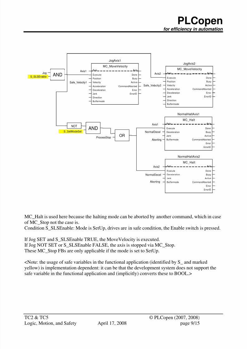
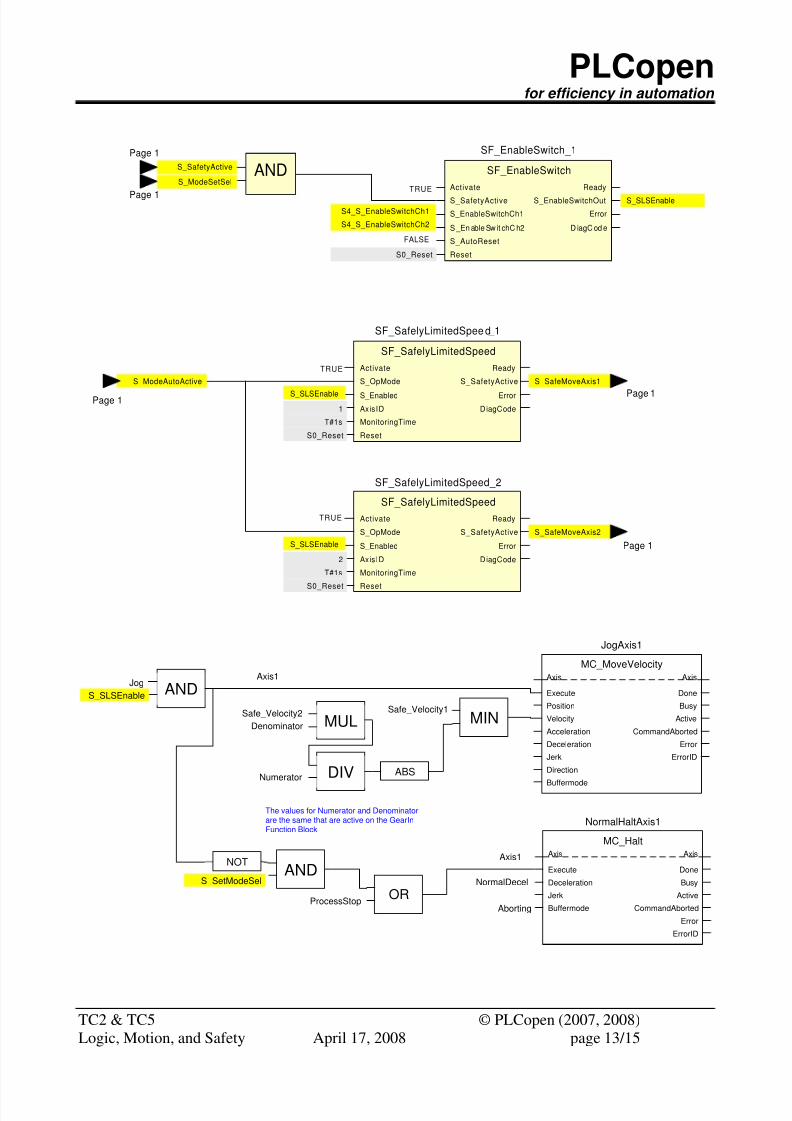
MC_Halt is used here because the halting mode can be aborted by another command, which in case
of MC_Stop not the case is.
Condition S_SLSEnable: Mode is SetUp, drives are in safe condition, the Enable switch is pressed.
If Jog SET and S_SLSEnable TRUE, the MoveVelocity is executed.
If Jog NOT SET or S_SLSEnable FALSE, the axis is stopped via MC_Stop.These MC_Stop FBs are only applicable if the mode is set to SetUp.
<Note: the usage of safe variables in the functional application (identified by S_ and marked
yellow) is implementation dependent: it can be that the development system does not support the
safe variable in the functional application and (implicitly) converts these to BOOL.>
Logic, Motion, and Safety April 17, 2008 page 9/15
8/8/2019 Logic Motion Safety v041
http://slidepdf.com/reader/full/logic-motion-safety-v041 10/15
PLCopenfor efficiency in automation
TC2 & TC5 © PLCopen (2007, 2008)
Axis
Enable
Axis
Status
MC_Power
PowerAxis1
Enable_Positive
Active
Busy
Buffermode
Enable_Negative
Error
ErrorID
Axis_1
TRUEFALSE
BM_Selected
Axis
TimeVelocity
Axis
TimeVelocity
MC_VelocityProfile
ProcessAxis1
Execute
TimeScale Busy
CommandAborted
BufferMode
Done
VelocityScale
Offset
Error
ErrorID
Active
BM_Selected
V_scaleT_scale
Axis
Execute
Axis
Done
MC_Stop
EStopAxis1
Deceleration
Active
CommandAborted
Busy
Buffermode
Jerk
Error
ErrorID
Axis_1
Safe_Decel
BM_SelectedJK_Selected
Velocity
0
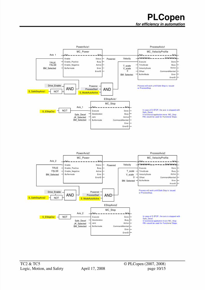
Powered
NOT In case of E-STOP, the axis is stopped with
Safe_Decel.
In functional application more ‘MC_Stop
FB’s would be used for Functional Stops.
Drive_Enable
ANDS_SafeStopAxis1 NOT
Axis
Enable
Axis
Status
MC_Power
PowerAxis2
Enable_Positive
Active
Busy
Buffermode
Enable_Negative
Error
ErrorID
Axis_2
TRUE
FALSE
BM_Selected
Axis
TimeVelocity
Axis
TimeVelocity
MC_VelocityProfile
ProcessAxis2
Execute
TimeScale Busy
CommandAborted
BufferMode
Done
VelocityScale
Offset
Error
ErrorID
Active
BM_Selected
V_scale
T_scale
Axis
Execute
Axis
Done
MC_Stop
EStopAxis2
Deceleration
Active
CommandAborted
Busy
Buffermode
Jerk
Error
ErrorID
Axis_2
Safe_Decel
BM_SelectedJK_Selected
Velocity
0
Powered
NOT
Process will work untill Safe Stop is issued
or ProcessStop.
In case of E-STOP , the axis is stopped with
Safe_Decel.
In functional application m ore ‘MC_Stop
FB’s would be used for Functional Stops.
Drive_Enable
ANDS_SafeStopAxis2 NOT
S_EStopOut
S_EStopOut
ProcessStart
Powered
ANDS_ModeAutoActive
ProcessStart
Powered
ANDS_ModeAutoActive
Process will work untill Safe Stop is issued
or ProcessStop.
Logic, Motion, and Safety April 17, 2008 page 10/15
8/8/2019 Logic Motion Safety v041
http://slidepdf.com/reader/full/logic-motion-safety-v041 11/15
PLCopenfor efficiency in automation
TC2 & TC5 © PLCopen (2007, 2008)
Logic, Motion, and Safety April 17, 2008 page 11/15
4 Machine example 2
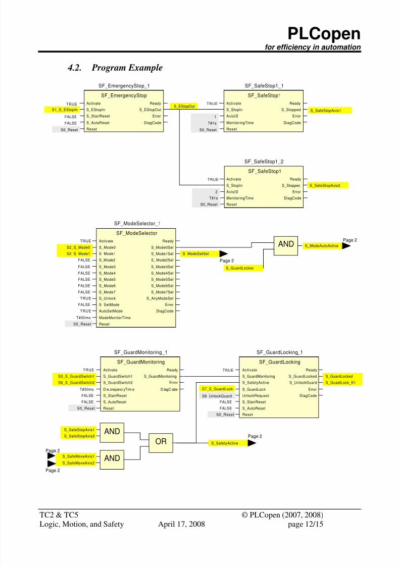
4.1. Introduction
This application also uses 2 axes, in this case related as master and slave via the gear functionality.
The safe part of the example is the same as in example 1 as the requirements for safety are the same,
e.g. a safety limited speed (SLS) functionality, which is activated via an enable switch, so material
could be taken out of the machine in practice, and mode selector, emergency stop, and guard
monitoring and locking.
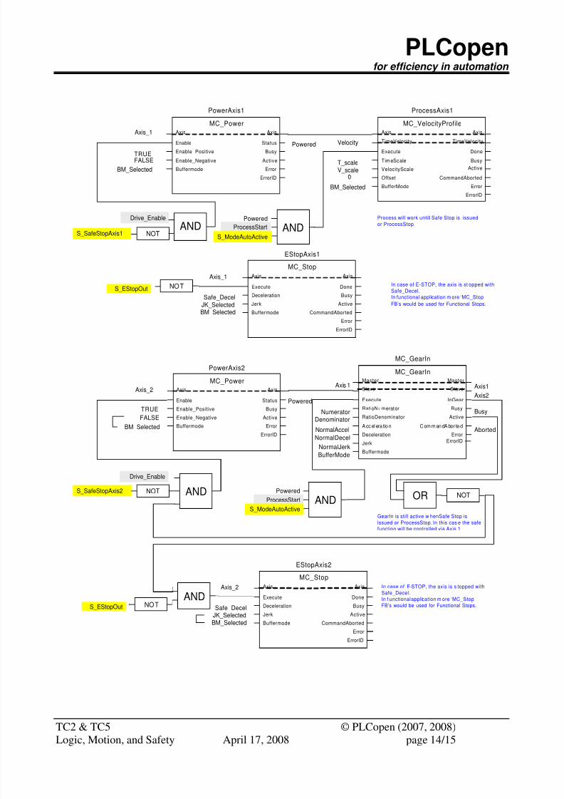
In order to fulfill the requirements in synchronized motion (GearIn in this case) the modifictions in
this example are only applied in the motion portion.
As the synchronization of the axes involved is required for every moment of the machine operation
all motion operations are only applied to the master axis as long as the synchronization is active.This allows applying all safety functions to the machine without causing any damage to it by
loosing the synchonisation.
In order to make sure that the right maximum value for the safe limied speed ist used for the master
axis the applied logic gives the right value by using he minimum value from axis 1 and axis 2
considering the used gear ratio.
The following safety principles are used in the application:
1.- Each of the axis in the machine has a certain absolute velocity (no kinematics involved) wich
makes that axis dangerous and should trigger safety fault in case it is exceeded.
2.- The speed relationships between the axes must be respected in order to continue the process of
the machine (this means that the slave axis cannot run at an arbitrary speed nor change the gear
ratio of without damaging the “production”).
3.- By lowering the master speed, all the synchronized axis to it proportionally lower their speeds.
This is a countermeasure to avoid the safety fault to be triggered, so should be applied while the
safety condition is applicable. The difference is that in this case both the master speed itself plus the
resulting speed on the slave through the ratio should be taken into account to choose the right
master reference.
4.- If the application requires variable ratios for slaves, always the worst case should be taken into
account in order to decide the amount of speed reduction in master (e.g. the highest ratio, or the
CAM points where slave speed is maximum). Although the application could establish this
maximum value during run time, and as such always optimizing the master reference to achieve the
maximum machine operation speed within the safety limits set, but this is not compulsory and
many times not a priority.
5.- And most important : the safety condition we want to check does not change regardless the type
of master-slave schema applied in the machine, because the safety functionality checks the velocity
conditions wich are dangerous in the machine. Safety does not care about synchronized axis or not.
8/8/2019 Logic Motion Safety v041
http://slidepdf.com/reader/full/logic-motion-safety-v041 12/15
PLCopenfor efficiency in automation
TC2 & TC5 © PLCopen (2007, 2008)
4.2. Program Example
Activate
S_EStopIn
Ready
S_EStopOut
SF_EmergencyStop
SF_EmergencyStop_1
S_StartReset
S_AutoReset
Error
DiagCode
ResetS0_Reset
TRUE
TRUE
S1_S_EStopIn
Page 2
Activate
S_StopIn
Ready
S_Stopped
SF_SafeStop1
SF_SafeStop1_1
AxisID
MonitoringTime
Error
DiagCode
ResetS0_Reset
T#1s
1
S_SafeStopAxis1
Activate
S_Mode0
Ready
S_Mode0Sel
SF_ModeSelector
SF_ModeSelector_1
S_Mode1
S_Mode2 S_ Mode2Sel
S_Mode3Sel
S_Mode5
S_Mode6
S_Unlock
AutoSetMode
ModeMonitorTime
S_Mode1Sel
S_SetMode
S_Mode7
S_Mode3
S_Mode4
Reset
S_Mode4Sel
S_Mode5Sel
S_Mode7Sel
S_AnyModeSel
S_Mode6Sel
Error
DiagCode
S2_S_Mode0
S2_S_Mode1
FALSE
FALSE
TRUE
S0_Reset
T#50ms
S_ModeAutoActive
S_ModeSetSel
TRUE
FALSE
FALSE
Activate
S_StopIn
Ready
S_Stopped
SF_SafeStop1
SF_SafeStop1_2
AxisID
MonitoringTime
Error
DiagCodeResetS0_Reset
T#1s
2
S_SafeStopAxis2
AND
Activate
S_GuardSwitch1
Ready
S_GuardMonitoring
SF_GuardMonitoring
SF_GuardMonitoring_1
S_GuardSwitch2
D is crepanc yTim e D iagC ode
S_StartResetS_AutoReset
Reset
Error
TRUE
S5_S_GuardSwitch1
S6_S_GuardSwitch2
T#50ms
FALSEFALSE
S0_Reset
Activate
S_GuardMonitoring
Ready
S_GuardLocked
SF_GuardLocking
SF_GuardLocking_1
S_SafetyActive
S_GuardLock Error
DiagCode
S_AutoReset
Reset
S_UnlockGuard
UnlockRequestS_StartReset
S_GuardLock_K1
S7_S_GuardLock
S8_UnlockGuard
FALSE
S0_Reset
FALSE
Page 2
S_SafeStopAxis1
S_SafeStopAxis2
ANDS_SafeMoveAxis1
S_SafeMoveAxis2
ORPage 2
Page 2
S_SafetyActive
S_GuardLocked
AND
S_GuardLocked
FALSE
FALSE
FALSE
FALSE
FALSE
TRUE
TRUE
TRUE
Page 2
S_EStopOut
Logic, Motion, and Safety April 17, 2008 page 12/15
8/8/2019 Logic Motion Safety v041
http://slidepdf.com/reader/full/logic-motion-safety-v041 13/15
PLCopenfor efficiency in automation
TC2 & TC5 © PLCopen (2007, 2008)
Activate
S_SafetyActive
Ready
S_EnableSwitchOut
SF_EnableSwitch
SF_EnableSwitch_1
S_EnableSwitchCh1
S _En able Sw it chC h2 D iagC od e
S_AutoReset
Reset
ErrorS4_S_EnableSwitchCh1
S4_S_EnableSwitchCh2
TRUE
FALSE
S0_Reset
Activate
S_OpMode
Ready
S_SafetyActive
SF_SafelyLimitedSpeed
SF_SafelyLimitedSpee d_1
S_Enabled
AxisID D iagCode
MonitoringTime
Reset
Error
S0_Reset
T#1s
1
S_SafeMoveAxis1
Activate
S_OpMode
Ready
S_SafetyActive
SF_SafelyLimitedSpeed
SF_SafelyLimitedSpeed_2
S_Enabled
AxisID D iagCode
MonitoringTime
Reset
Error
S0_Reset
T#1s
2
S_SafeMoveAxis2
S_SLSEnable
S_SLSEnable
S_SLSEnable
S_SafetyActive
Page 1
S_ModeSetSel
Page 1
AND
S_ModeAutoActive
Page 1 Page 1
Page 1
TRUE
TRUE
Safe_Velocity1
JogAxis1 Axis
Execute
Axis
Done
MC_MoveVelocity
JogAxis1
Position
Velocity Active
CommandAborted
Jerk
Direction
Busy
Buffermode
Acceleration
Deceleration Error
ErrorID
ANDS_SLSEnable
Axis
Execute
Axis
Done
MC_Halt
NormalHaltAxis1
Deceleration
Active
CommandAborted
Busy
Buffermode
Jerk
Error
ErrorID
NOT
Aborting
Axis1
ANDS_SetModeSel NormalDecel
ORProcessStop
MINSafe_Velocity2
DIV
MUL
Numerator
Denominator
The values for Numerator and Denominatorare the same that are active on the GearInFunction Block
ABS
Logic, Motion, and Safety April 17, 2008 page 13/15
8/8/2019 Logic Motion Safety v041
http://slidepdf.com/reader/full/logic-motion-safety-v041 14/15
PLCopenfor efficiency in automation
TC2 & TC5 © PLCopen (2007, 2008)
Axis
Enable
Axis
Status
MC_Power
PowerAxis1
Enable_Positive
Active
Busy
Buffermode
Enable_Negative
Error
ErrorID
Axis_1
TRUEFALSE
BM_Selected
Axis
TimeVelocity
Axis
TimeVelocity
MC_VelocityProfile
ProcessAxis1
Execute
TimeScale Busy
CommandAborted
BufferMode
Done
VelocityScale
Offset
Error
ErrorID
Active
BM_Selected
V_scaleT_scale
Axis
Execute
Axis
Done
MC_Stop
EStopAxis1
Deceleration
Active
CommandAborted
Busy
Buffermode
Jerk
Error
ErrorID
Axis_1
Safe_Decel
BM_SelectedJK_Selected
Velocity
0
Powered
NOT In case of E-STOP, the axis is st opped with
Safe_Decel.
In functional application m ore ‘MC_Stop
FB’s would be used for Functional Stops.
Drive_Enable
ANDS_SafeStopAxis1 NOT
Axis
Enable
Axis
Status
MC_Power
PowerAxis2
Enable_Positive
Active
Busy
BuffermodeEnable_Negative
Error
ErrorID
Axis_2
TRUE
FALSEBM_Selected
Axis
Execute
Axis
Done
MC_Stop
EStopAxis2
Deceleration
Active
CommandAborted
Busy
Buffermode
Jerk
Error
ErrorID
Axis_2
Safe_Decel
BM_SelectedJK_Selected
Powered
GearIn is still active w henSafe Stop is
issued or ProcessStop. In this cas e the safe
function will be controlled via Axis 1
In case of E-STOP, the axis is s topped with
Safe_Decel.
In f unctional application m ore ‘MC_Stop
FB’s would be used for Functional Stops.
Drive_Enable
S_SafeStopAxis2
S_EStopOut
S_EStopOut
ProcessStart
Powered
ANDS_ModeAutoActive
ProcessStart
Powered
ANDS_ModeAutoActive
Process will work untill Safe Stop is issued
or ProcessStop.
NOTAND
ANDNOTNOT
Master
Slave
Master
Slave
MC_GearIn
MC_GearIn
Execute
RatioNumerator Busy
Active
Deceleration
Jerk
InGear
Buffermode
RatioDenominator
A cc el era tio n C om m an dA bor te d
Error
ErrorID
Numerator
DenominatorNormalAccel
NormalDecel
NormalJerk
BufferMode
Axis 1
Axis2
Axis1
Busy
Aborted
OR
Logic, Motion, and Safety April 17, 2008 page 14/15
8/8/2019 Logic Motion Safety v041
http://slidepdf.com/reader/full/logic-motion-safety-v041 15/15
PLCopenfor efficiency in automation
TC2 & TC5 © PLCopen (2007, 2008)
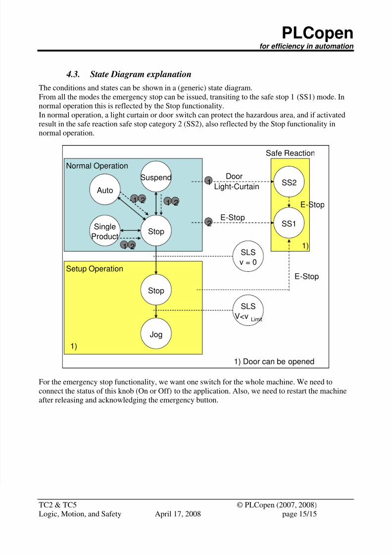
4.3. State Diagram explanation
The conditions and states can be shown in a (generic) state diagram.
From all the modes the emergency stop can be issued, transiting to the safe stop 1 (SS1) mode. Innormal operation this is reflected by the Stop functionality.
In normal operation, a light curtain or door switch can protect the hazardous area, and if activated
result in the safe reaction safe stop category 2 (SS2), also reflected by the Stop functionality in
normal operation.
Logic, Motion, and Safety April 17, 2008 page 15/15
Auto
Single
Product
SuspendSS2
SS1
SLS
V<v Limit
E-Stop
Door
Light-Curtain
Stop
Jog
E - Stop
Stop
Normal Operation
Setup Operation
SLS
v = 0
Safe Reaction
E - Stop
1
2
1 21 2
1 2
1)
1)
1) Door can be opened
For the emergency stop functionality, we want one switch for the whole machine. We need to
connect the status of this knob (On or Off) to the application. Also, we need to restart the machineafter releasing and acknowledging the emergency button.
Recommended