Introduction 1-1
Chapter 1Introduction
slides are modified from J. Kurose & K. Ross
CPE 400 / 600Computer Communication Networks
Lecture 2

Introduction 1-2
Chapter 1: IntroductionGoal: get “feel” and terminology more depth, detail later in course
Overview: what’s the Internet? what’s a protocol? network edge; hosts, access net, physical media network core: packet/circuit switching, Internet structure performance: loss, delay, throughput protocol layers, service models security history

Introduction 1-3
What’s the Internet: “nuts and bolts” view millions of connected
computing devices: hosts = end systems
Home network
Institutional network
Mobile network
Global ISP
Regional ISP
communication links transmission rate =
bandwidth
routers: forward packets
protocols control sending, receiving of msgs
Internet: “network of networks”

Introduction 1-4
What’s the Internet: a service view communication
infrastructure enables distributed applications: Web, VoIP, email, games,
e-commerce, file sharing
communication services provided to apps: reliable data delivery
from source to destination
“best effort” (unreliable) data delivery

Introduction 1-5
What’s a protocol?human protocols: “what’s the time?” “I have a question” introductions
… specific msgs sent… specific actions taken when msgs
received, or other events
network protocols: machines rather than
humans all communication activity
in Internet governed by protocols
protocols define format, order of msgs sent and received among network entities, and
actions taken on msg transmission, receipt

Introduction 1-6
Network Security attacks on Internet infrastructure:
infecting/attacking hosts: malware, spyware, virus, worms
unauthorized access (data stealing, user accounts)
denial of service: deny access to resources (servers, link bandwidth)
Packet sniffing: ethereal Masquerade: IP spoofing
Internet not originally designed with (much) security in mind original vision: “a group of mutually trusting
users attached to a transparent network”

Introduction 1-7
Lecture: roadmap
1.1 What is the Internet?1.2 Network edge
end systems access networks links
1.3 Network core circuit switching packet switching network structure

Introduction 1-8
A closer look at network structure:
network edge: applications and hosts
access networks, physical media: wired, wireless communication links
network core: interconnected routers network of networks
Introduction 1-9
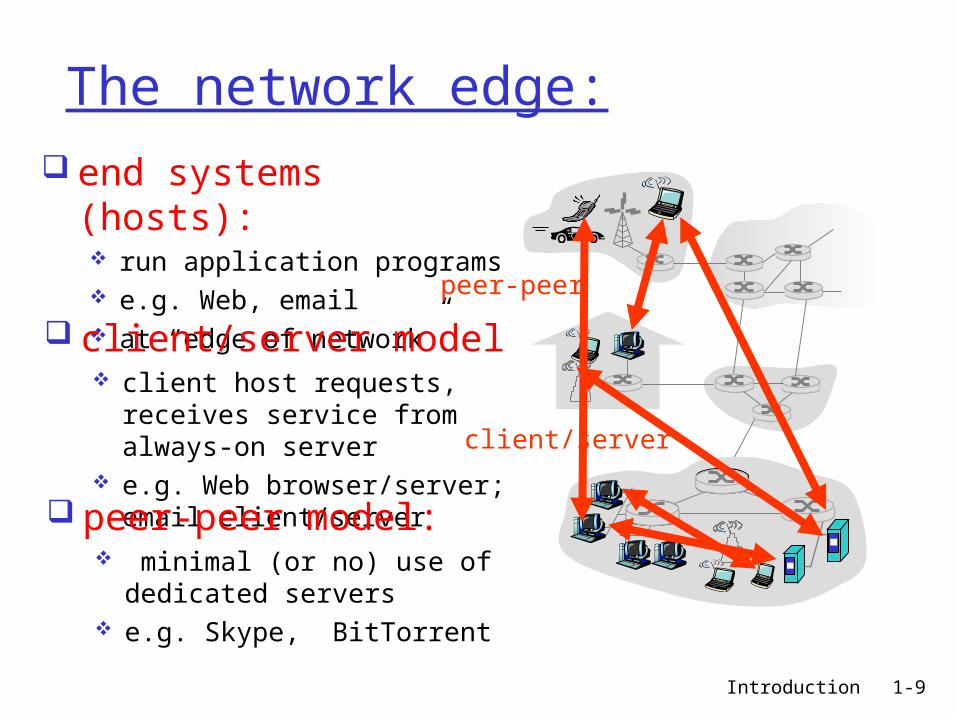
The network edge: end systems (hosts):
run application programs e.g. Web, email at “edge of network”
client/server
peer-peer
client/server model client host requests,
receives service from always-on server
e.g. Web browser/server; email client/server peer-peer model:
minimal (or no) use of dedicated servers
e.g. Skype, BitTorrent

Introduction 1-10
Network edge: reliable data transfer service
Goal: data transfer between end systems handshaking: prepare for data transfer ahead of
time Hello, hello back human protocol set up “state” in two communicating hosts
TCP - Transmission Control Protocol [RFC 793] Internet’s reliable data transfer service
reliable, in-order byte-stream data transfer loss: acknowledgements and retransmissions
flow control: sender won’t overwhelm receiver
congestion control: senders “slow down sending rate” when network congested

Introduction 1-11
Network edge: (best effort)unreliable data transfer service
Goal: data transfer between end systems same as before!
UDP - User Datagram Protocol [RFC 768]: connectionless unreliable data transfer no flow control no congestion control
App’s using UDP: streaming media,
teleconferencing, DNS, Internet telephony
App’s using TCP: SMTP (email), HTTP
(Web), FTP (file transfer), Telnet (remote login)

Introduction 1-12
Access networks and physical media
Q: How to connect end systems to edge router?
residential access nets institutional access
networks (school, company) mobile access networks
Keep in mind: bandwidth (bits per second)
of access network? shared or dedicated?

Introduction 1-13
Residential access: point to point access Dialup via modem
up to 56Kbps direct access to router (often less)
Can’t surf and phone at same time: can’t be “always on”
DSL: digital subscriber line deployment: telephone company (typically) up to 1 Mbps upstream up to 8 Mbps downstream dedicated physical line to telephone central
office

Introduction 1-14
Residential access: cable modems
HFC: hybrid fiber coax asymmetric: up to 30Mbps downstream,
2 Mbps upstream
network of cable and fiber attaches homes to ISP router homes share access to router
deployment: available via cable TV companies

Introduction 1-15
Cable Network Architecture: Overview
home
cable headend
cable distributionnetwork (simplified)
Typically 500 to 5,000 homes

Introduction 1-16
Cable Network Architecture: Overview
home
cable headend
cable distributionnetwork
server(s)

Introduction 1-17
Cable Network Architecture: Overview
home
cable headend
cable distributionnetwork (simplified)

Introduction 1-18
Cable Network Architecture: Overview
home
cable headend
cable distributionnetwork
Channels
VIDEO
VIDEO
VIDEO
VIDEO
VIDEO
VIDEO
DATA
DATA
CONTROL
1 2 3 4 5 6 7 8 9
FDM (more shortly):

Introduction 1-19
Company access: local area networks
company/university local area network (LAN) connects end system to edge router
Ethernet: 10 Mbs, 100Mbps,
1Gbps, 10Gbps Ethernet
modern configuration: end systems connect into Ethernet switch

Introduction 1-20
Wireless access networks
shared wireless access network connects end system to router via base station aka “access
point”
wireless LANs: 802.11b/g (WiFi): 11 or 54 Mbps
wider-area wireless access provided by telecom operator ~1Mbps over cellular system
(EVDO, HSDPA) next up (?): WiMAX (10’s Mbps)
over wide area
basestation
mobilehosts
router

Introduction 1-21
Home networks
Typical home network components: DSL or cable modem router/firewall/NAT Ethernet wireless access point
wirelessaccess point
wirelesslaptops
router/firewall
cablemodem
to/fromcable
headend
Ethernet

Introduction 1-22
Physical Media Bit: propagates between transmitter/rcvr pairs physical link: what lies between transmitter &
receiver guided media:
signals propagate in solid media: copper, fiber, coax
unguided media: signals propagate freely, e.g., radio
Twisted Pair (TP) two insulated copper wires
Category 3: traditional phone wires, 10 Mbps Ethernet
Category 5: 100Mbps Ethernet

Introduction 1-23
Physical Media: coax, fiber
Coaxial cable: two concentric copper conductors bidirectional Baseband: single channel on cable, legacy Ethernet Broadband: multiple channels on cable, HFC
Fiber optic cable: glass fiber carrying light pulses, each pulse a bit high-speed operation:
high-speed point-to-point transmission (e.g., 10’s-100’s Gps)
low error rate: repeaters spaced far apart immune to electromagnetic noise
Introduction 1-24
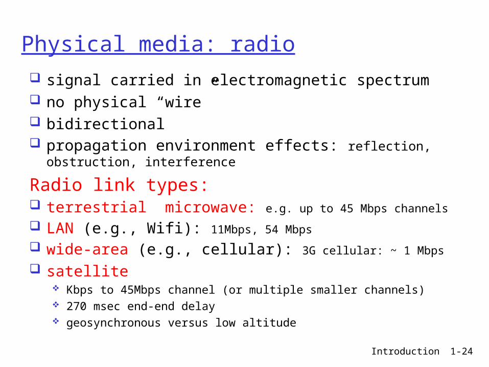
Physical media: radio
signal carried in electromagnetic spectrum no physical “wire” bidirectional propagation environment effects: reflection,
obstruction, interference
Radio link types: terrestrial microwave: e.g. up to 45 Mbps channels
LAN (e.g., Wifi): 11Mbps, 54 Mbps
wide-area (e.g., cellular): 3G cellular: ~ 1 Mbps
satellite Kbps to 45Mbps channel (or multiple smaller channels) 270 msec end-end delay geosynchronous versus low altitude

Introduction 1-25
Lecture 2: roadmap
1.1 What is the Internet?1.2 Network edge
end systems access networks links
1.3 Network core circuit switching packet switching network structure

Introduction 1-26
The Network Core mesh of interconnected
routers
the fundamental question: how is data transferred through network?
circuit switching: dedicated circuit per call: telephone network
packet-switching: data sent thru network in discrete “chunks”

Introduction 1-27
Network Core: Circuit Switching
End-end resources reserved for “call”
link bandwidth switch capacity dedicated resources:
no sharing
circuit-like performance guaranteed
call setup required

Introduction 1-28
Network Core: Circuit Switching
network resources (e.g., bandwidth) divided into “pieces” pieces allocated to calls resource piece idle if not used by owning
call (no sharing)
dividing link bandwidth into “pieces” frequency division time division

Introduction 1-29
Circuit Switching: FDM and TDM
FDM
frequency
time
TDM
frequency
time
4 users
Example:

Introduction 1-30
Numerical example
How long does it take to send a file of 640,000 bits from host A to host B over a circuit-switched network? All links are 1.536 Mbps Each link uses TDM with 24 slots/sec 500 msec to establish end-to-end circuit

Introduction 1-31
Network Core: Packet Switchingeach end-end data stream divided into packets user's packets share network resources
each packet uses full link bandwidth resources used as needed
resource contention: aggregate resource demand
can exceed amount available congestion: packets queue, wait for link use store and forward: packets move one hop at a time
Node receives complete packet before forwarding
Bandwidth division into “pieces”
Dedicated allocationResource reservation

Introduction 1-32
Packet Switching: Statistical Multiplexing
Sequence of packets does not have fixed pattern, bandwidth shared on demand
A
B
C100 Mb/sEthernet
1.5 Mb/s
D E
statistical multiplexing
queue of packetswaiting for output
link

Introduction 1-33
Packet-switching: store-and-forward
takes L/R seconds to transmit (push out) packet of L bits on to link at R bps
store and forward: entire packet must arrive at router before it can be transmitted on next link
delay = 3L/R (assuming zero propagation delay)
Example: L = 7.5 Mbits R = 1.5 Mbps transmission delay = 15 sec
R R RL

Introduction 1-34
Packet switching versus circuit switching 1 Mb/s link each user:
100 kb/s when “active” active 10% of time
circuit-switching: 10 users
packet switching: with 35 users, probability > 10
active at same time is less than .0004
Packet switching allows more users to use network!
N users
1 Mbps link

Introduction 1-35
Packet switching versus circuit switching
great for bursty data resource sharing simpler, no call setup
excessive congestion: packet delay and loss protocols needed for reliable data transfer,
congestion control Q: How to provide circuit-like behavior?
bandwidth guarantees needed for audio/video apps
still an unsolved problem
Is packet switching a “slam dunk winner?”
Q: human analogies of reserved resources (circuit switching) versus on-demand allocation (packet-switching)?

Introduction 1-36
Internet structure: network of networks
roughly hierarchical at center: “tier-1” ISPs (e.g., Verizon, Sprint, AT&T,
Cable and Wireless), national/international coverage treat each other as equals
Tier 1 ISP
Tier 1 ISP
Tier 1 ISP
Tier-1 providers interconnect (peer) privately

Introduction 1-37
Tier-1 ISP: e.g., Sprint
…
to/from customers
peering
to/from backbone
….
………
POP: point-of-presence

Introduction 1-38
Internet structure: network of networks
“Tier-2” ISPs: smaller (often regional) ISPs Connect to one or more tier-1 ISPs, possibly other tier-2 ISPs
Tier 1 ISP
Tier 1 ISP
Tier 1 ISP
Tier-2 ISPTier-2 ISP
Tier-2 ISP Tier-2 ISP
Tier-2 ISP
Tier-2 ISP pays tier-1 ISP for connectivity to rest of Internet
tier-2 ISP is customer of tier-1 provider
Tier-2 ISPs also peer privately with each other

Introduction 1-39
Internet structure: network of networks
“Tier-3” ISPs and local ISPs last hop (“access”) network (closest to end systems)
Tier 1 ISP
Tier 1 ISP
Tier 1 ISP
Tier-2 ISPTier-2 ISP
Tier-2 ISP Tier-2 ISP
Tier-2 ISP
localISPlocal
ISPlocalISP
localISP
localISP Tier 3
ISP
localISP
localISP
localISP
Local and tier- 3 ISPs are customers ofhigher tier ISPsconnecting them to res of Internet

Introduction 1-40
Internet structure: network of networks
a packet passes through many networks!
Tier 1 ISP
Tier 1 ISP
Tier 1 ISP
Tier-2 ISPTier-2 ISP
Tier-2 ISP Tier-2 ISP
Tier-2 ISP
localISPlocal
ISPlocalISP
localISP
localISP Tier 3
ISP
localISP
localISP
localISP

Introduction 1-41
Lecture 2: SummaryCovered a “ton” of material! Internet overview what’s a protocol? network edge, core, access network
packet-switching vs circuit-switching Internet structure
You now have: context, overview, “feel” of networking more depth, detail to follow!
Recommended