IntesisBox® DK-RC-MBS-1 v.1.6
Modbus RTU (EIA-485) Interface for Daikin air conditioners. Compatible with VRV and SKY line air conditioners commercialized by Daikin.
User Manual Issue Date: 12/2017
r3.3 EN
Order Codes:
DK-RC-MBS-1: Modbus RTU Interface for Daikin air conditioners
DK-RC-MBS-1 User’s Manual r3.3 EN
© Intesis Software S.L.U. - All rights reserved This information is subject to change without notice
IntesisBox® is a registered trademark of Intesis Software SLU
URL
Phone
http://www.intesisbox.com
+34 938047134
2/23
© Intesis Software S.L.U. 2017. All Rights Reserved.
Information in this document is subject to change without notice. No part of this publication
may be reproduced, stored in a retrieval system or transmitted in any form or any means
electronic or mechanical, including photocopying and recording for any purpose other than the
purchaser’s personal use without the written permission of Intesis Software S.L.U.
Intesis Software S.L.U. Milà i Fontanals, 1 bis 08700 Igualada Spain TRADEMARKS
All trademarks and tradenames used in this document are acknowledged to be the copyright of
their respective holders.
DK-RC-MBS-1 User’s Manual r3.3 EN
© Intesis Software S.L.U. - All rights reserved This information is subject to change without notice
IntesisBox® is a registered trademark of Intesis Software SLU
URL
Phone
http://www.intesisbox.com
+34 938047134
3/23
INDEX
1. Presentation .......................................................................................................... 4
2. Connection ............................................................................................................ 5
2.1 Connect to the AC indoor unit ............................................................................... 5
2.2 Connection to the EIA-485 bus ............................................................................. 6
3. Quick Start Guide ................................................................................................... 6
4. Modbus Interface Specification ................................................................................ 7
4.1 Modbus physical layer.......................................................................................... 7
4.2 Modbus Registers ................................................................................................ 7
4.2.1 Control and status registers ........................................................................... 7
4.2.2 Configuration Registers.................................................................................. 9
4.2.3 Considerations on Temperature Registers ........................................................ 9
4.3 DIP-switch Configuration Interface ...................................................................... 11
4.4 Implemented Functions ..................................................................................... 15
4.5 Device LED indicator ......................................................................................... 15
4.6 EIA-485 bus. Termination resistors and Fail-Safe Biasing mechanism ...................... 16
5. Electrical and Mechanical features .......................................................................... 17
6. List of supported AC Unit Types. ............................................................................ 18
7. Error Codes ......................................................................................................... 19
8. Annex 1: Master/Slave of Operation Mode ............................................................... 23
DK-RC-MBS-1 User’s Manual r3.3 EN
© Intesis Software S.L.U. - All rights reserved This information is subject to change without notice
IntesisBox® is a registered trademark of Intesis Software SLU
URL
Phone
http://www.intesisbox.com
+34 938047134
4/23
1. Presentation
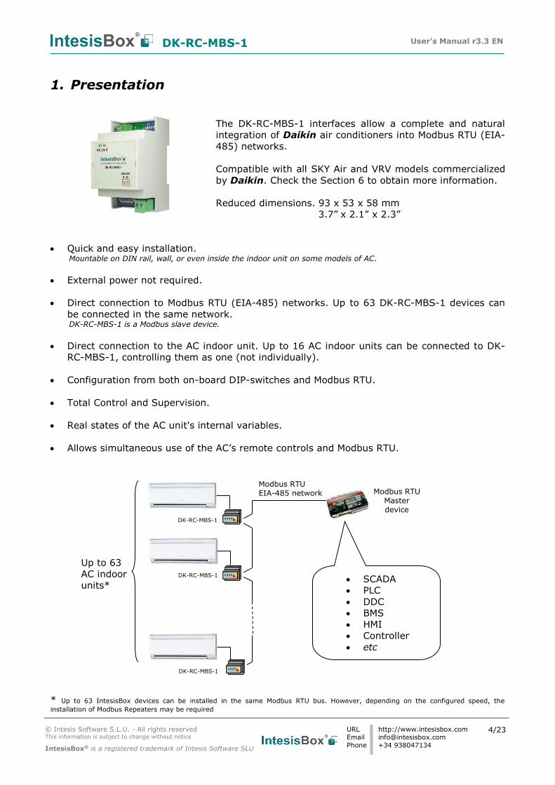
The DK-RC-MBS-1 interfaces allow a complete and natural
integration of Daikin air conditioners into Modbus RTU (EIA-
485) networks.
Compatible with all SKY Air and VRV models commercialized
by Daikin. Check the Section 6 to obtain more information.
Reduced dimensions. 93 x 53 x 58 mm
3.7” x 2.1” x 2.3”
• Quick and easy installation. Mountable on DIN rail, wall, or even inside the indoor unit on some models of AC.
• External power not required.
• Direct connection to Modbus RTU (EIA-485) networks. Up to 63 DK-RC-MBS-1 devices can
be connected in the same network. DK-RC-MBS-1 is a Modbus slave device.
• Direct connection to the AC indoor unit. Up to 16 AC indoor units can be connected to DK-
RC-MBS-1, controlling them as one (not individually).
• Configuration from both on-board DIP-switches and Modbus RTU.
• Total Control and Supervision.
• Real states of the AC unit's internal variables.
• Allows simultaneous use of the AC’s remote controls and Modbus RTU.
* Up to 63 IntesisBox devices can be installed in the same Modbus RTU bus. However, depending on the configured speed, the
installation of Modbus Repeaters may be required
• SCADA
• PLC
• DDC
• BMS
• HMI
• Controller
• etc
Up to 63
AC indoor
units*
Modbus RTU EIA-485 network
Modbus RTU Master device
DK-RC-MBS-1
DK-RC-MBS-1
DK-RC-MBS-1
DK-RC-MBS-1 User’s Manual r3.3 EN
© Intesis Software S.L.U. - All rights reserved This information is subject to change without notice
IntesisBox® is a registered trademark of Intesis Software SLU
URL
Phone
http://www.intesisbox.com
+34 938047134
5/23
Connection to
P1P2 bus. Two wire cable.
90 mm / 3.5”
53 mm / 2.1”
53 mm / 2.1”
90 mm 3.5”
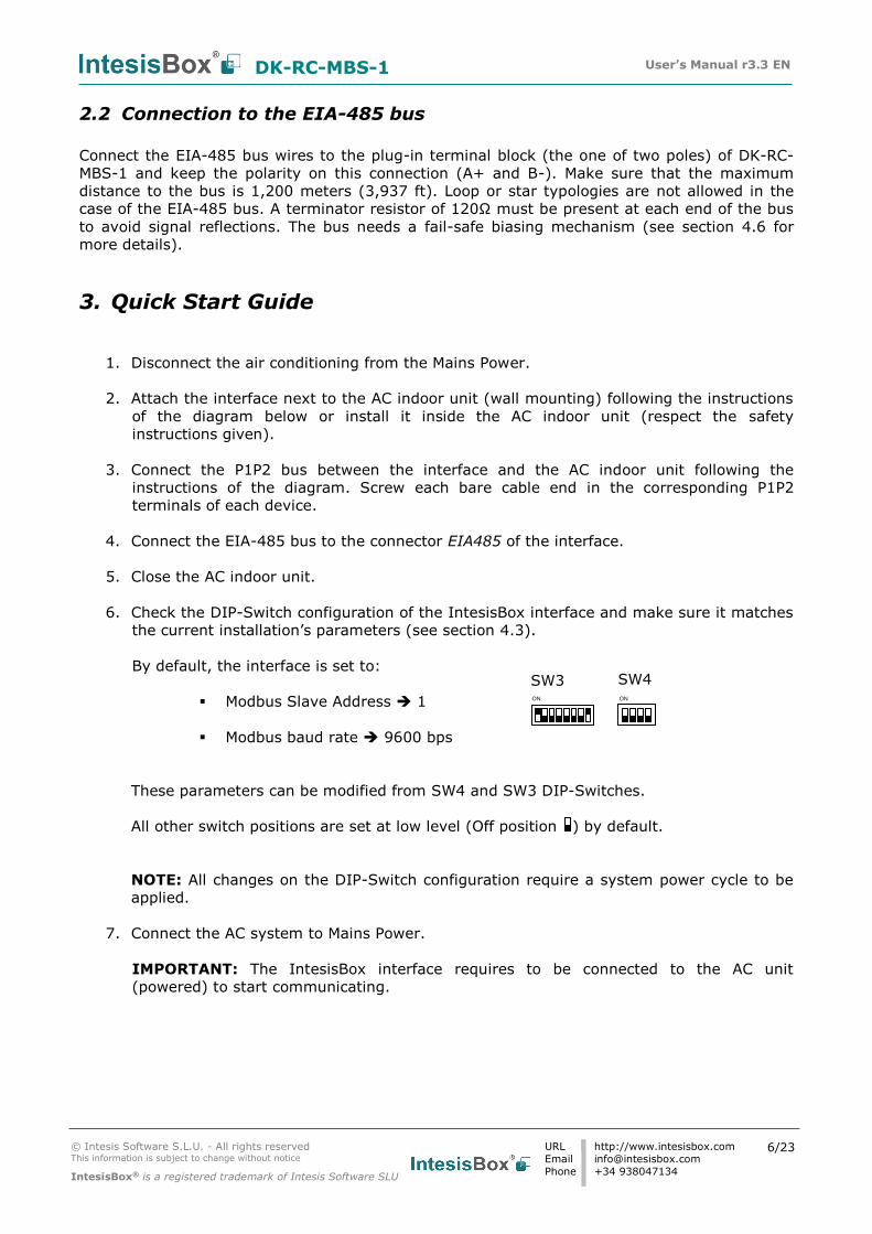
2. Connection
The interface comes with a plug-in terminal block of 2 poles to establish direct connection with
the AC indoor unit. It comes as well with a plug-in terminal block of 2 poles to establish direct
connection with the Modbus RTU EIA-485 network.
2.1 Connect to the AC indoor unit
The DK-RC-MBS-1 connects directly to the Daikin P1P2 Bus, which is not provided within the
interface. Depending on which controllers are available, the recommended connection’ methods
are the following ones (details in Figure 2. 1):
• Wired remote control available. Connect the gateway as Slave in parallel with the
wired remote controllers (Controller acts as Master).
• Infrared remote control available. Connect the gateway as Master in parallel with the
infrared remote controller (Infrared Remote Control as Slave).
• No remote control available Connect the gateway directly to the P1P2 bus of the
indoor unit as Master when there is no Daikin Remote Controller.
Maximum P1 P2 bus length is 500 meters / 1,640.42 ft . The bus has no polarity sensitivity.
AC Indoor Unit
IntesisBox® DK-RC-MBS-1
MODBUS RTU
EIA-485 Bus
EIA485 A+ B-
P1 P2 AC Unit
For wall mounting extract the upper and lower staples until you hear the "click".
P1 P2
DAIKIN
Internal electronic control board
Remote Controller
P2 P1
IntesisBox® DK-RC-MBS-1
MODBUS RTU
EIA-485 Bus
EIA485 A+ B-
P1 P2 AC Unit
AC Indoor Unit
Internal electronic control board
Connection to P1P2 bus. Two wire cable.
P2 P1
Max. 500m / 1,640.42 ft
Max. 500m / 1,640.42 ft
Figure 2. 1 DK-RC-MBS-1 Connection diagrams
DK-RC-MBS-1 User’s Manual r3.3 EN
© Intesis Software S.L.U. - All rights reserved This information is subject to change without notice
IntesisBox® is a registered trademark of Intesis Software SLU
URL
Phone
http://www.intesisbox.com
+34 938047134
6/23
2.2 Connection to the EIA-485 bus
Connect the EIA-485 bus wires to the plug-in terminal block (the one of two poles) of DK-RC-
MBS-1 and keep the polarity on this connection (A+ and B-). Make sure that the maximum
distance to the bus is 1,200 meters (3,937 ft). Loop or star typologies are not allowed in the
case of the EIA-485 bus. A terminator resistor of 120Ω must be present at each end of the bus
to avoid signal reflections. The bus needs a fail-safe biasing mechanism (see section 4.6 for
more details).
3. Quick Start Guide
1. Disconnect the air conditioning from the Mains Power.
2. Attach the interface next to the AC indoor unit (wall mounting) following the instructions
of the diagram below or install it inside the AC indoor unit (respect the safety
instructions given).
3. Connect the P1P2 bus between the interface and the AC indoor unit following the
instructions of the diagram. Screw each bare cable end in the corresponding P1P2
terminals of each device.
4. Connect the EIA-485 bus to the connector EIA485 of the interface.
5. Close the AC indoor unit.
6. Check the DIP-Switch configuration of the IntesisBox interface and make sure it matches
the current installation’s parameters (see section 4.3).
By default, the interface is set to:
Modbus Slave Address 1
Modbus baud rate 9600 bps
These parameters can be modified from SW4 and SW3 DIP-Switches.
All other switch positions are set at low level (Off position ) by default.
NOTE: All changes on the DIP-Switch configuration require a system power cycle to be
applied.
7. Connect the AC system to Mains Power.
IMPORTANT: The IntesisBox interface requires to be connected to the AC unit
(powered) to start communicating.
ON ON
SW3 SW4
DK-RC-MBS-1 User’s Manual r3.3 EN
© Intesis Software S.L.U. - All rights reserved This information is subject to change without notice
IntesisBox® is a registered trademark of Intesis Software SLU
URL
Phone
http://www.intesisbox.com
+34 938047134
7/23
4. Modbus Interface Specification
4.1 Modbus physical layer
DK-RC-MBS-1 implements a Modbus RTU (Slave) interface, to be connected to an EIA-485 line.
It performs 8N2 communication (8 data bits, no parity and 2 stop bit) with several available
baud rates (2400 bps, 4800 bps, 9600 bps -default-, 19200 bps, 38400 bps, 57600 bps, 76800
bps and 115200 bps). It also supports 8N1 communication (8 data bits, no parity and 1 stop
bit).
4.2 Modbus Registers
All registers are type “16-bit unsigned Holding Register” and they use the standard Modbus big
endian notation.
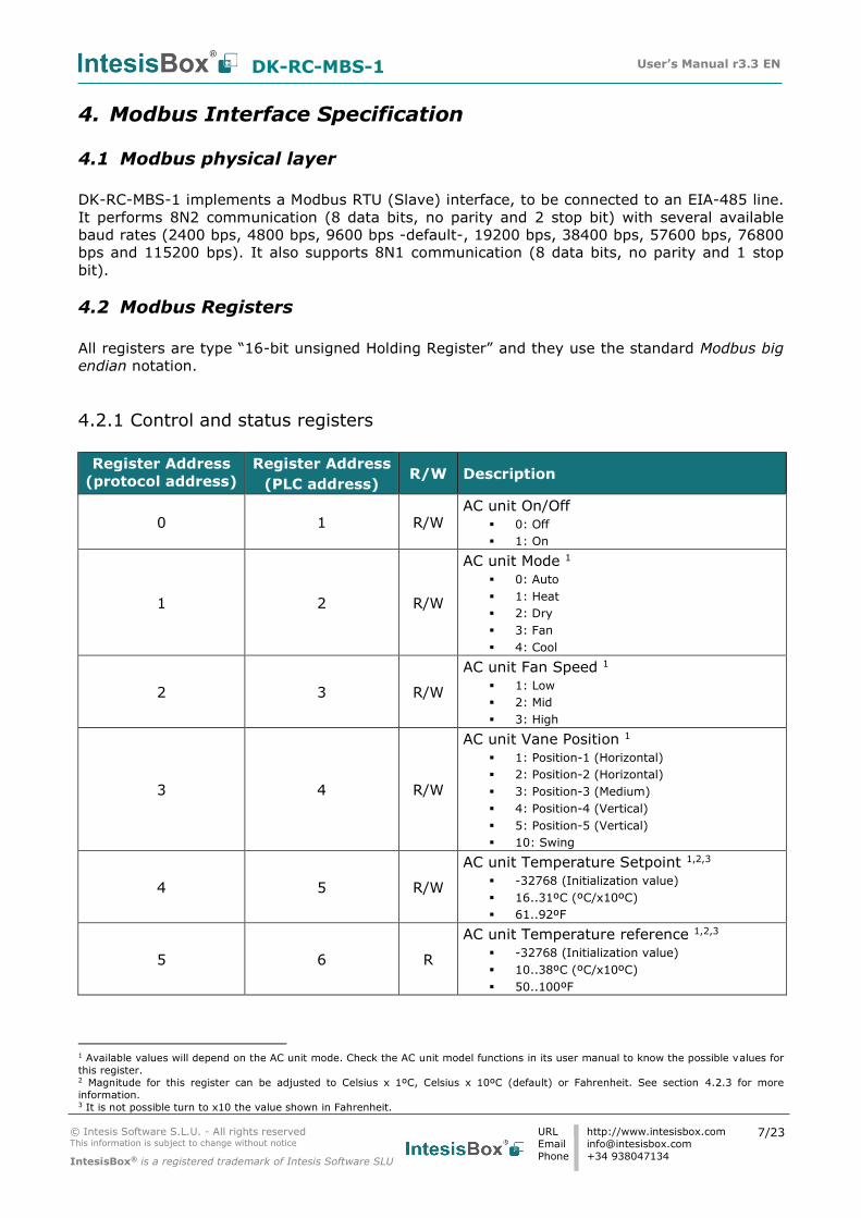
4.2.1 Control and status registers
Register Address
(protocol address)
Register Address
(PLC address) R/W Description
0 1 R/W AC unit On/Off
0: Off
1: On
1 2 R/W
AC unit Mode 1
0: Auto
1: Heat
2: Dry
3: Fan
4: Cool
2 3 R/W
AC unit Fan Speed 1
1: Low
2: Mid
3: High
3 4 R/W
AC unit Vane Position 1
1: Position-1 (Horizontal)
2: Position-2 (Horizontal)
3: Position-3 (Medium)
4: Position-4 (Vertical)
5: Position-5 (Vertical)
10: Swing
4 5 R/W
AC unit Temperature Setpoint 1,2,3
-32768 (Initialization value)
16..31ºC (ºC/x10ºC)
61..92ºF
5 6 R
AC unit Temperature reference 1,2,3
-32768 (Initialization value)
10..38ºC (ºC/x10ºC)
50..100ºF
1 Available values will depend on the AC unit mode. Check the AC unit model functions in its user manual to know the possible values for
this register. 2 Magnitude for this register can be adjusted to Celsius x 1ºC, Celsius x 10ºC (default) or Fahrenheit. See section 4.2.3 for more
information. 3 It is not possible turn to x10 the value shown in Fahrenheit.
DK-RC-MBS-1 User’s Manual r3.3 EN
© Intesis Software S.L.U. - All rights reserved This information is subject to change without notice
IntesisBox® is a registered trademark of Intesis Software SLU
URL
Phone
http://www.intesisbox.com
+34 938047134
8/23
Register Address
(protocol address)
Register Address
(PLC address) R/W Description
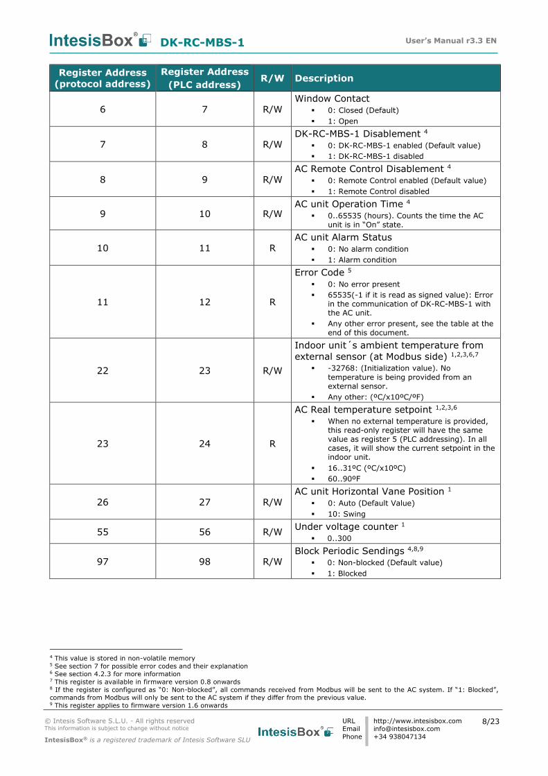
6 7 R/W Window Contact
0: Closed (Default)
1: Open
7 8 R/W DK-RC-MBS-1 Disablement 4
0: DK-RC-MBS-1 enabled (Default value)
1: DK-RC-MBS-1 disabled
8 9 R/W AC Remote Control Disablement 4
0: Remote Control enabled (Default value)
1: Remote Control disabled
9 10 R/W AC unit Operation Time 4
0..65535 (hours). Counts the time the AC unit is in “On” state.
10 11 R AC unit Alarm Status
0: No alarm condition
1: Alarm condition
11 12 R
Error Code 5
0: No error present
65535(-1 if it is read as signed value): Error in the communication of DK-RC-MBS-1 with the AC unit.
Any other error present, see the table at the
end of this document.
22 23 R/W
Indoor unit´s ambient temperature from
external sensor (at Modbus side) 1,2,3,6,7 -32768: (Initialization value). No
temperature is being provided from an external sensor.
Any other: (ºC/x10ºC/ºF)
23 24 R
AC Real temperature setpoint 1,2,3,6 When no external temperature is provided,
this read-only register will have the same value as register 5 (PLC addressing). In all cases, it will show the current setpoint in the indoor unit.
16..31ºC (ºC/x10ºC)
60..90ºF
26 27 R/W AC unit Horizontal Vane Position 1
0: Auto (Default Value) 10: Swing
55 56 R/W Under voltage counter 1
0..300
97 98 R/W Block Periodic Sendings 4,8,9
0: Non-blocked (Default value)
1: Blocked
4 This value is stored in non-volatile memory 5 See section 7 for possible error codes and their explanation 6 See section 4.2.3 for more information 7 This register is available in firmware version 0.8 onwards 8 If the register is configured as “0: Non-blocked”, all commands received from Modbus will be sent to the AC system. If “1: Blocked”,
commands from Modbus will only be sent to the AC system if they differ from the previous value. 9 This register applies to firmware version 1.6 onwards
DK-RC-MBS-1 User’s Manual r3.3 EN
© Intesis Software S.L.U. - All rights reserved This information is subject to change without notice
IntesisBox® is a registered trademark of Intesis Software SLU
URL
Phone
http://www.intesisbox.com
+34 938047134
9/23
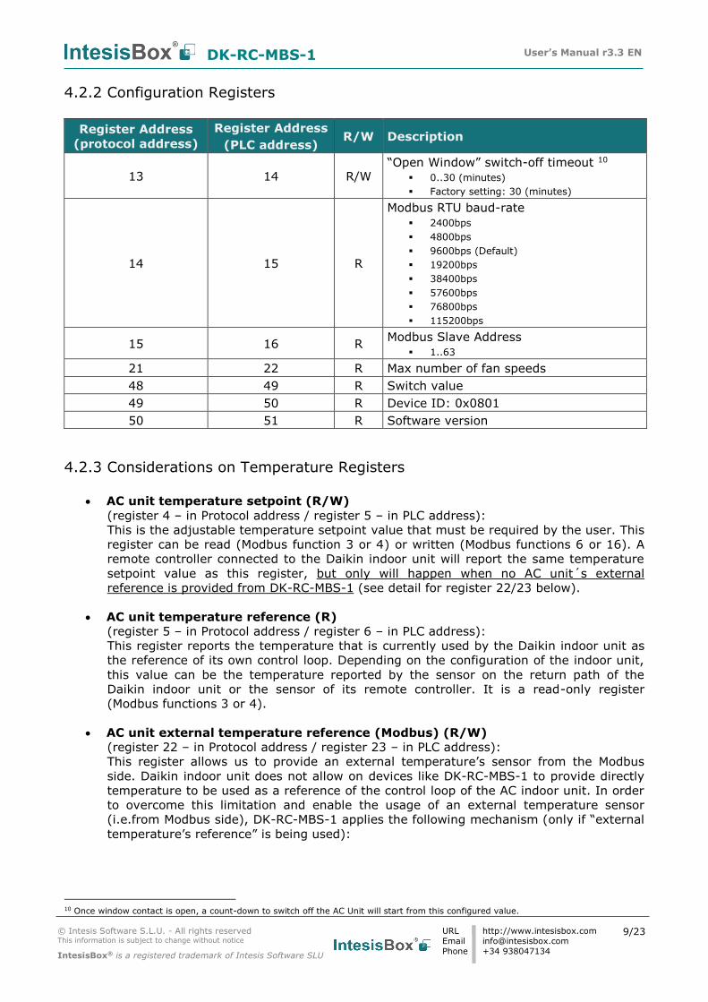
4.2.2 Configuration Registers
Register Address
(protocol address)
Register Address
(PLC address) R/W Description
13 14 R/W “Open Window” switch-off timeout 10
0..30 (minutes)
Factory setting: 30 (minutes)
14 15 R
Modbus RTU baud-rate
2400bps
4800bps
9600bps (Default)
19200bps
38400bps
57600bps
76800bps
115200bps
15 16 R Modbus Slave Address
1..63
21 22 R Max number of fan speeds
48 49 R Switch value
49 50 R Device ID: 0x0801
50 51 R Software version
4.2.3 Considerations on Temperature Registers
• AC unit temperature setpoint (R/W)
(register 4 – in Protocol address / register 5 – in PLC address):
This is the adjustable temperature setpoint value that must be required by the user. This
register can be read (Modbus function 3 or 4) or written (Modbus functions 6 or 16). A
remote controller connected to the Daikin indoor unit will report the same temperature
setpoint value as this register, but only will happen when no AC unit´s external
reference is provided from DK-RC-MBS-1 (see detail for register 22/23 below).
• AC unit temperature reference (R)
(register 5 – in Protocol address / register 6 – in PLC address):
This register reports the temperature that is currently used by the Daikin indoor unit as
the reference of its own control loop. Depending on the configuration of the indoor unit,
this value can be the temperature reported by the sensor on the return path of the
Daikin indoor unit or the sensor of its remote controller. It is a read-only register
(Modbus functions 3 or 4).
• AC unit external temperature reference (Modbus) (R/W)
(register 22 – in Protocol address / register 23 – in PLC address):
This register allows us to provide an external temperature’s sensor from the Modbus
side. Daikin indoor unit does not allow on devices like DK-RC-MBS-1 to provide directly
temperature to be used as a reference of the control loop of the AC indoor unit. In order
to overcome this limitation and enable the usage of an external temperature sensor
(i.e.from Modbus side), DK-RC-MBS-1 applies the following mechanism (only if “external
temperature’s reference” is being used):
10 Once window contact is open, a count-down to switch off the AC Unit will start from this configured value.
DK-RC-MBS-1 User’s Manual r3.3 EN
© Intesis Software S.L.U. - All rights reserved This information is subject to change without notice
IntesisBox® is a registered trademark of Intesis Software SLU
URL
Phone
http://www.intesisbox.com
+34 938047134
10/23
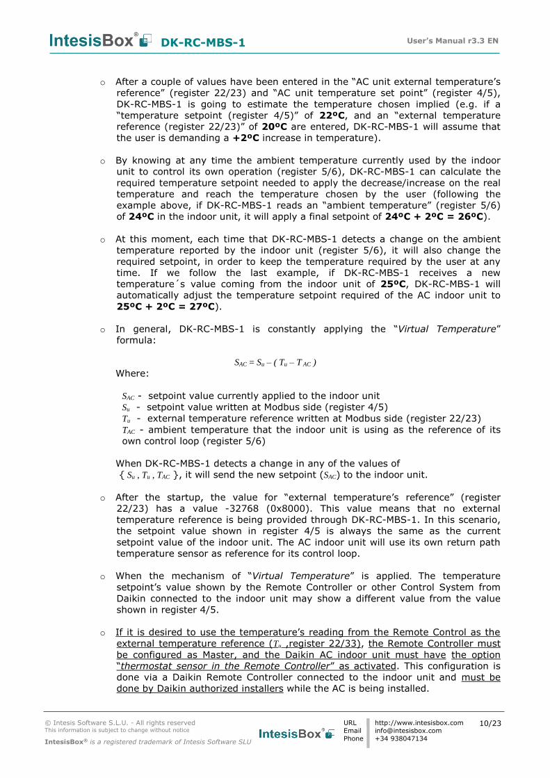
o After a couple of values have been entered in the “AC unit external temperature’s
reference” (register 22/23) and “AC unit temperature set point” (register 4/5),
DK-RC-MBS-1 is going to estimate the temperature chosen implied (e.g. if a
“temperature setpoint (register 4/5)” of 22ºC, and an “external temperature
reference (register 22/23)” of 20ºC are entered, DK-RC-MBS-1 will assume that
the user is demanding a +2ºC increase in temperature).
o By knowing at any time the ambient temperature currently used by the indoor
unit to control its own operation (register 5/6), DK-RC-MBS-1 can calculate the
required temperature setpoint needed to apply the decrease/increase on the real
temperature and reach the temperature chosen by the user (following the
example above, if DK-RC-MBS-1 reads an “ambient temperature” (register 5/6)
of 24ºC in the indoor unit, it will apply a final setpoint of 24ºC + 2ºC = 26ºC).
o At this moment, each time that DK-RC-MBS-1 detects a change on the ambient
temperature reported by the indoor unit (register 5/6), it will also change the
required setpoint, in order to keep the temperature required by the user at any
time. If we follow the last example, if DK-RC-MBS-1 receives a new
temperature´s value coming from the indoor unit of 25ºC, DK-RC-MBS-1 will
automatically adjust the temperature setpoint required of the AC indoor unit to
25ºC + 2ºC = 27ºC).
o In general, DK-RC-MBS-1 is constantly applying the “Virtual Temperature”
formula:
SAC = Su – ( Tu – T AC )
Where:
SAC - setpoint value currently applied to the indoor unit
Su - setpoint value written at Modbus side (register 4/5)
Tu - external temperature reference written at Modbus side (register 22/23)
TAC - ambient temperature that the indoor unit is using as the reference of its
own control loop (register 5/6)
When DK-RC-MBS-1 detects a change in any of the values of
Su , Tu , TAC , it will send the new setpoint (SAC) to the indoor unit.
o After the startup, the value for “external temperature’s reference” (register
22/23) has a value -32768 (0x8000). This value means that no external
temperature reference is being provided through DK-RC-MBS-1. In this scenario,
the setpoint value shown in register 4/5 is always the same as the current
setpoint value of the indoor unit. The AC indoor unit will use its own return path
temperature sensor as reference for its control loop.
o When the mechanism of “Virtual Temperature” is applied. The temperature
setpoint’s value shown by the Remote Controller or other Control System from
Daikin connected to the indoor unit may show a different value from the value
shown in register 4/5.
o If it is desired to use the temperature’s reading from the Remote Control as the
external temperature reference (Tu ,register 22/33), the Remote Controller must
be configured as Master, and the Daikin AC indoor unit must have the option
“thermostat sensor in the Remote Controller” as activated. This configuration is
done via a Daikin Remote Controller connected to the indoor unit and must be
done by Daikin authorized installers while the AC is being installed.
DK-RC-MBS-1 User’s Manual r3.3 EN
© Intesis Software S.L.U. - All rights reserved This information is subject to change without notice
IntesisBox® is a registered trademark of Intesis Software SLU
URL
Phone
http://www.intesisbox.com
+34 938047134
11/23
o When DK-RC-MBS-1 is set as “Master” of P1P2 bus, the external temperature’s
sensor connected to Modbus RTU EIA-485 network provides directly the value
currently applied to the indoor unit ( SAC ), and the process of the Virtual
temperature is not applied. In this case, the Remote Controller or any other
Control System connected from Daikin is not able to send the external
temperature reference’s value to the register 22/23.
• AC Real temperature setpoint (R)
(register 23 – In Protocol address / register 24 – in PLC address):
As it has been detailed on the previous point, the real temperature setpoint in the indoor
unit and the temperature setpoint requested from DK-RC-MBS-1 might differ (when a
value in register 22/23 – “external temperature reference” is entered). This register
always informs about the current temperature setpoint which is being used by the indoor
unit – it is also includes the temperature setpoint that will be shown by an additional
remote controller from Daikin connected to the indoor unit, if it is present on the system.
Moreover, notice that temperature’s values of all these four registers are expressed according to
the temperature´s format configured through its onboard DIP-Switches (See “4.3 - DIP-switch
Configuration Interface”). These following formats are possible:
• Celsius value: Value in Modbus register is the temperature value in Celsius (i.e. a
value “22” in the Modbus register must be interpreted as 22ºC)
• Decicelsius value: Value in Modbus register is the temperature value in
decicelsius (i.e. a value “220” in the Modbus register must be interpreted as
22.0ºC)
• Fahrenheit value: Value in Modbus register is the temperature value in
Fahrenheit (i.e. a value “72” in the Modbus register must be interpreted as 72ºF
(~22ºC).
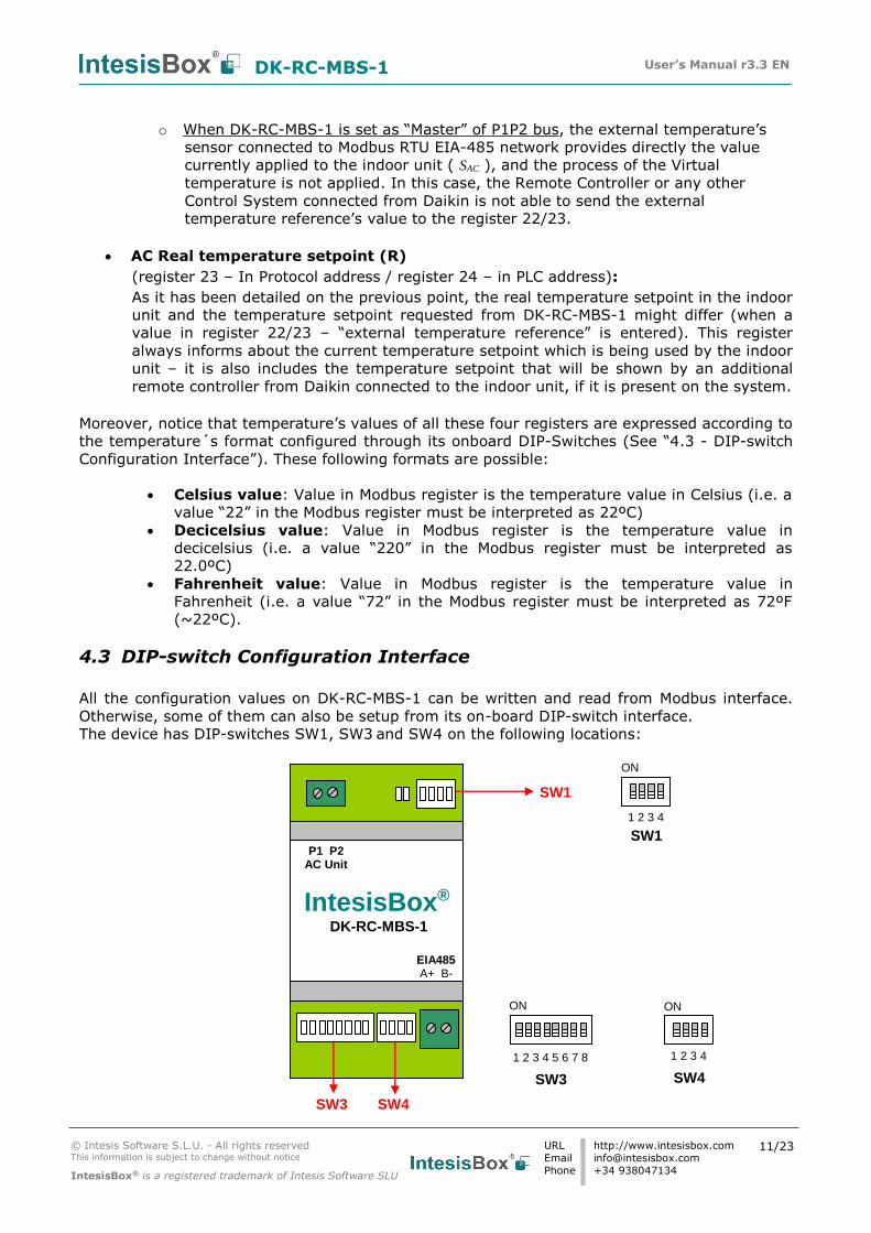
4.3 DIP-switch Configuration Interface
All the configuration values on DK-RC-MBS-1 can be written and read from Modbus interface.
Otherwise, some of them can also be setup from its on-board DIP-switch interface.
The device has DIP-switches SW1, SW3 and SW4 on the following locations:
SW3 SW4
IntesisBox® DK-RC-MBS-1
EIA485 A+ B-
P1 P2 AC Unit
SW1
SW1
SW4
ON
1 2 3 4
ON
SW3
1 2 3 4
1 2 3 4 5 6 7 8
ON
DK-RC-MBS-1 User’s Manual r3.3 EN
© Intesis Software S.L.U. - All rights reserved This information is subject to change without notice
IntesisBox® is a registered trademark of Intesis Software SLU
URL
Phone
http://www.intesisbox.com
+34 938047134
12/23
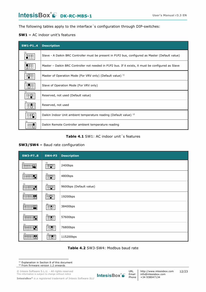
The following tables apply to the interface´s configuration through DIP-switches:
SW1 – AC indoor unit’s features
SW1-P1..4 Description
Slave - A Daikin BRC Controller must be present in P1P2 bus, configured as Master (Default value)
Master – Daikin BRC Controller not needed in P1P2 bus. If it exists, it must be configured as Slave
Master of Operation Mode (For VRV only) (Default value) 11
Slave of Operation Mode (For VRV only)
Reserved, not used (Default value)
Reserved, not used
Daikin Indoor Unit ambient temperature reading (Default value) 12
Daikin Remote Controller ambient temperature reading
Table 4.1 SW1: AC indoor unit´s features
SW3/SW4 – Baud rate configuration
SW3-P7..8 SW4-P3 Description
2400bps
4800bps
9600bps (Default value)
19200bps
38400bps
57600bps
76800bps
115200bps
Table 4.2 SW3-SW4: Modbus baud rate
11 Explanation in Section 8 of this document 12 From firmware version 1.2 onwards
ON ON
ON ON
ON ON
ON ON
ON ON
ON ON
ON ON
ON ON
ON
ON
ON
ON
ON
ON
ON
ON
DK-RC-MBS-1 User’s Manual r3.3 EN
© Intesis Software S.L.U. - All rights reserved This information is subject to change without notice
IntesisBox® is a registered trademark of Intesis Software SLU
URL
Phone
http://www.intesisbox.com
+34 938047134
13/23
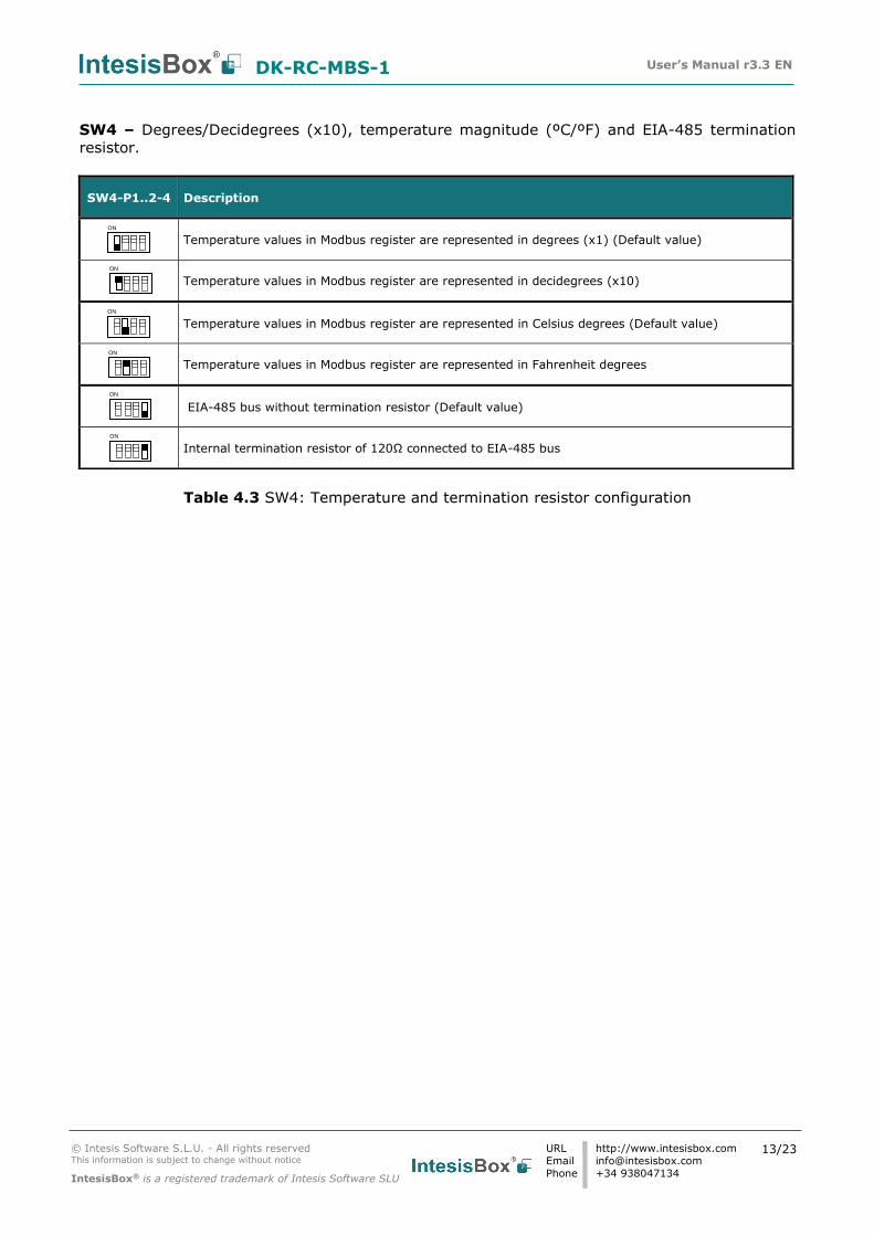
SW4 – Degrees/Decidegrees (x10), temperature magnitude (ºC/ºF) and EIA-485 termination
resistor.
Table 4.3 SW4: Temperature and termination resistor configuration
SW4-P1..2-4 Description
Temperature values in Modbus register are represented in degrees (x1) (Default value)
Temperature values in Modbus register are represented in decidegrees (x10)
Temperature values in Modbus register are represented in Celsius degrees (Default value)
Temperature values in Modbus register are represented in Fahrenheit degrees
EIA-485 bus without termination resistor (Default value)
Internal termination resistor of 120Ω connected to EIA-485 bus
ON
ON
ON
ON
ON
ON
DK-RC-MBS-1 User’s Manual r3.3 EN
© Intesis Software S.L.U. - All rights reserved This information is subject to change without notice
IntesisBox® is a registered trademark of Intesis Software SLU
URL
Phone
http://www.intesisbox.com
+34 938047134
14/23
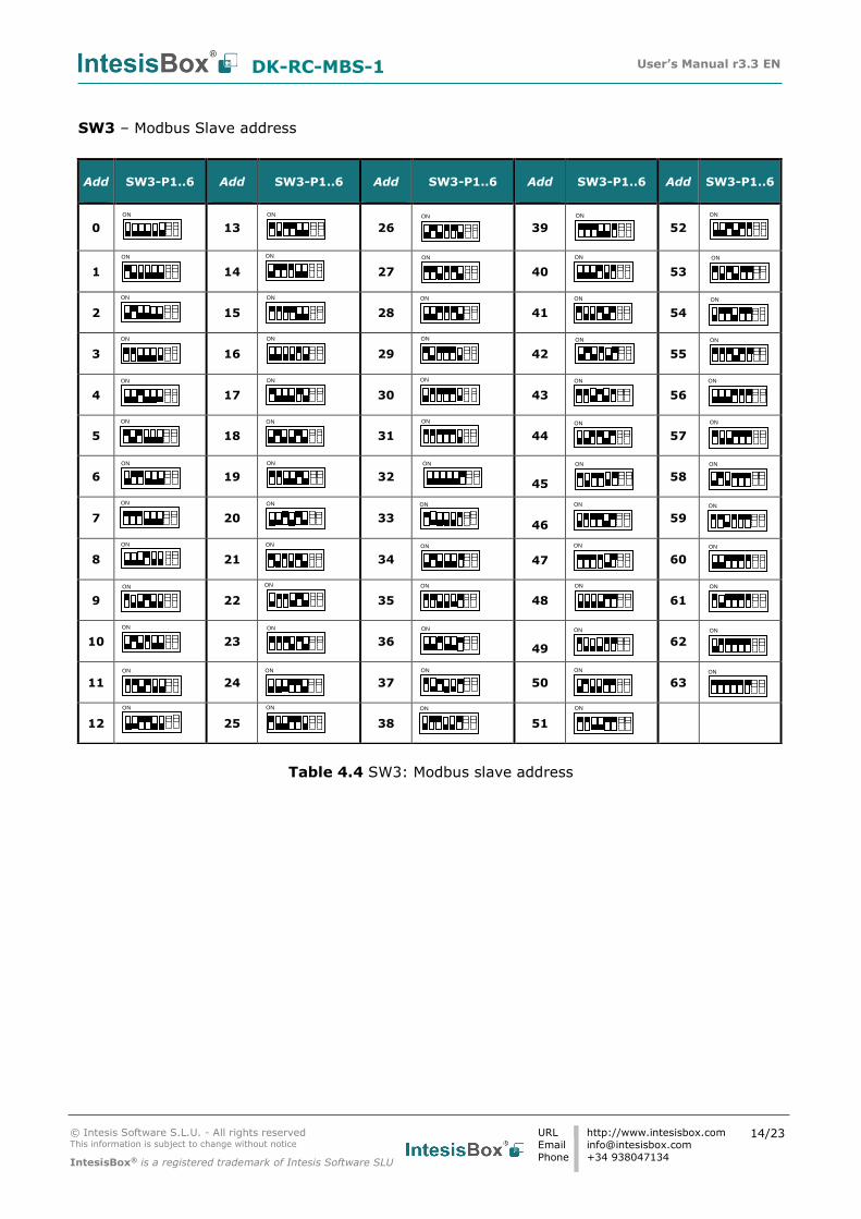
SW3 – Modbus Slave address
Table 4.4 SW3: Modbus slave address
Add
SW3-P1..6
Add
SW3-P1..6
Add
SW3-P1..6
Add
SW3-P1..6
Add
SW3-P1..6
0
13
26
39
52
1
14
27
40
53
2
15
28
41
54
3
16
29
42
55
4
17
30
43
56
5
18
31
44
57
6
19
32
45
58
7
20
33
46
59
8
21
34
47
60
9
22
35
48
61
10
23
36
49
62
11
24
37
50
63
12
25
38
51
ON
ON
ON
ON
ON
ON
ON
ON
ON
ON
ON
ON
ON
ON
ON
ON
ON
ON
ON
ON
ON
ON
ON
ON
ON
ON
ON
ON
ON
ON
ON
ON
ON
ON
ON
ON
ON
ON
ON
ON
ON
ON
ON
ON
ON
ON
ON
ON
ON
ON
ON
ON
ON
ON
ON
ON
ON
ON
ON
ON
ON
ON
ON
ON
DK-RC-MBS-1 User’s Manual r3.3 EN
© Intesis Software S.L.U. - All rights reserved This information is subject to change without notice
IntesisBox® is a registered trademark of Intesis Software SLU
URL
Phone
http://www.intesisbox.com
+34 938047134
15/23
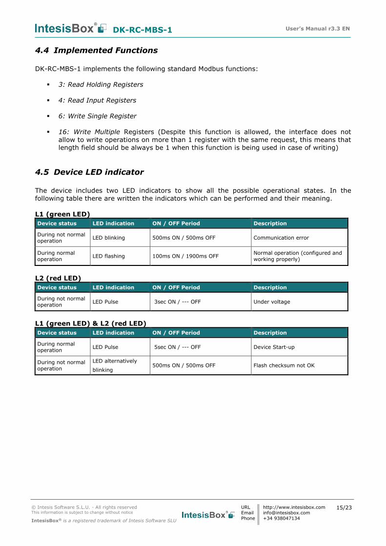
4.4 Implemented Functions
DK-RC-MBS-1 implements the following standard Modbus functions:
3: Read Holding Registers
4: Read Input Registers
6: Write Single Register
16: Write Multiple Registers (Despite this function is allowed, the interface does not
allow to write operations on more than 1 register with the same request, this means that
length field should be always be 1 when this function is being used in case of writing)
4.5 Device LED indicator
The device includes two LED indicators to show all the possible operational states. In the
following table there are written the indicators which can be performed and their meaning.
L1 (green LED)
Device status LED indication ON / OFF Period Description
During not normal operation
LED blinking 500ms ON / 500ms OFF Communication error
During normal operation
LED flashing 100ms ON / 1900ms OFF Normal operation (configured and working properly)
L2 (red LED)
Device status LED indication ON / OFF Period Description
During not normal operation
LED Pulse 3sec ON / --- OFF Under voltage
L1 (green LED) & L2 (red LED)
Device status LED indication ON / OFF Period Description
During normal operation
LED Pulse 5sec ON / --- OFF Device Start-up
During not normal operation
LED alternatively
blinking 500ms ON / 500ms OFF Flash checksum not OK
DK-RC-MBS-1 User’s Manual r3.3 EN
© Intesis Software S.L.U. - All rights reserved This information is subject to change without notice
IntesisBox® is a registered trademark of Intesis Software SLU
URL
Phone
http://www.intesisbox.com
+34 938047134
16/23
4.6 EIA-485 bus. Termination resistors and Fail-Safe Biasing
mechanism
EIA-485 bus requires a 120Ω terminator resistor at each end of the bus to avoid signal
reflections.
In order to prevent fail status detected by the receivers, which are “listening” the bus, when all
the transmitters’ outputs are in three-state (high impedance), it is also required a fail-safe
biasing mechanism. This mechanism provides a safe status (a correct voltage level) in the bus
when all the transmitters’ outputs are in three-state. This mechanism must be supplied by the
Modbus Master.
The DK-RC-MBS-1 device includes an on-board terminator resistor of 120Ω that can be
connected to the EIA-485 bus by using DIP-switch SW4.
Some Modbus RTU EIA-485 Master devices can provide also internal 120Ω terminator resistor
and/or fail-safe biasing mechanism (check the technical documentation of the Master device
connected to the EIA-485 network in each case).
DK-RC-MBS-1 User’s Manual r3.3 EN
© Intesis Software S.L.U. - All rights reserved This information is subject to change without notice
IntesisBox® is a registered trademark of Intesis Software SLU
URL
Phone
http://www.intesisbox.com
+34 938047134
17/23
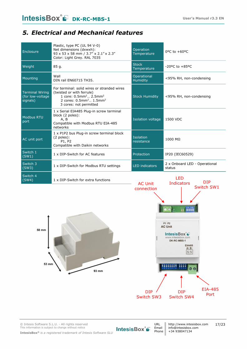
5. Electrical and Mechanical features
Enclosure
Plastic, type PC (UL 94 V-0) Net dimensions (dxwxh): 93 x 53 x 58 mm / 3.7” x 2.1” x 2.3” Color: Light Grey. RAL 7035
Operation Temperature
0ºC to +60ºC
Weight 85 g. Stock Temperature
-20ºC to +85ºC
Mounting Wall DIN rail EN60715 TH35.
Operational Humidity
<95% RH, non-condensing
Terminal Wiring (for low-voltage signals)
For terminal: solid wires or stranded wires (twisted or with ferrule)
1 core: 0.5mm2… 2.5mm2 2 cores: 0.5mm2… 1.5mm2
3 cores: not permitted
Stock Humidity <95% RH, non-condensing
Modbus RTU port
1 x Serial EIA485 Plug-in screw terminal block (2 poles):
A, B Compatible with Modbus RTU EIA-485 networks
Isolation voltage 1500 VDC
AC unit port
1 x P1P2 bus Plug-in screw terminal block (2 poles):
P1, P2 Compatible with Daikin networks
Isolation resistance
1000 MΩ
Switch 1 (SW1)
1 x DIP-Switch for AC features Protection IP20 (IEC60529)
Switch 3 (SW3)
1 x DIP-Switch for Modbus RTU settings LED indicators 2 x Onboard LED - Operational status
Switch 4 (SW4)
1 x DIP-Switch for extra functions
EIA-485
Port
AC Unit
connection
DIP
Switch SW3
DIP
Switch SW1
LED
Indicators
DIP
Switch SW4

DK-RC-MBS-1 User’s Manual r3.3 EN
© Intesis Software S.L.U. - All rights reserved This information is subject to change without notice
IntesisBox® is a registered trademark of Intesis Software SLU
URL
Phone
http://www.intesisbox.com
+34 938047134
18/23
6. List of supported AC Unit Types.
A list of Daikin indoor unit model’s references compatible with DK-RC-MBS-1 and its available
features can be found on this link:
https://www.intesisbox.com/intesis/support/compatibilities/IntesisBox_DK-RC-xxx-1_AC_Compatibility.pdf
DK-RC-MBS-1 User’s Manual r3.3 EN
© Intesis Software S.L.U. - All rights reserved This information is subject to change without notice
IntesisBox® is a registered trademark of Intesis Software SLU
URL
Phone
http://www.intesisbox.com
+34 938047134
19/23
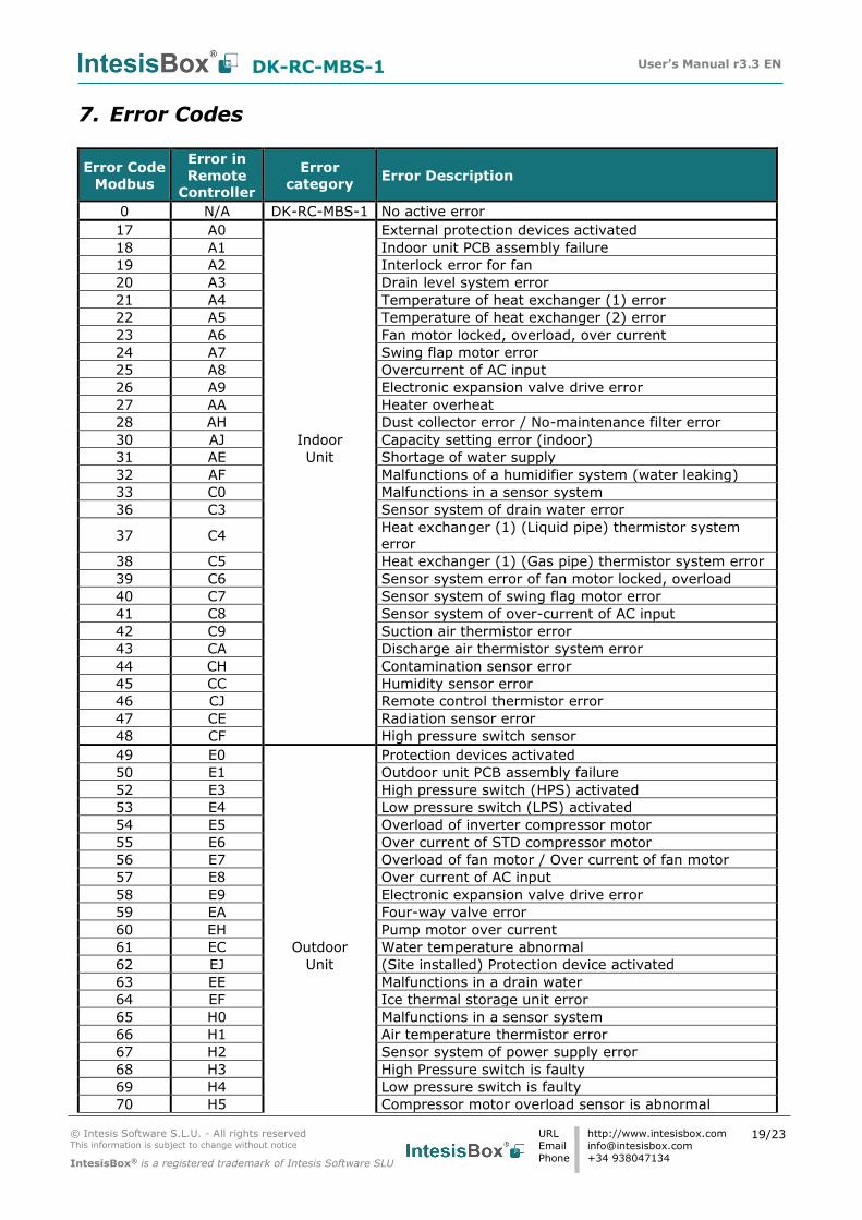
7. Error Codes
Error Code
Modbus
Error in
Remote
Controller
Error
category Error Description
0 N/A DK-RC-MBS-1 No active error
17 A0 External protection devices activated
18 A1 Indoor unit PCB assembly failure
19 A2 Interlock error for fan
20 A3 Drain level system error
21 A4 Temperature of heat exchanger (1) error
22 A5 Temperature of heat exchanger (2) error
23 A6 Fan motor locked, overload, over current
24 A7 Swing flap motor error
25 A8 Overcurrent of AC input
26 A9 Electronic expansion valve drive error
27 AA Heater overheat
28 AH Dust collector error / No-maintenance filter error
30 AJ Indoor Capacity setting error (indoor)
31 AE Unit Shortage of water supply
32 AF Malfunctions of a humidifier system (water leaking)
33 C0 Malfunctions in a sensor system
36 C3 Sensor system of drain water error
37 C4 Heat exchanger (1) (Liquid pipe) thermistor system
error
38 C5 Heat exchanger (1) (Gas pipe) thermistor system error
39 C6 Sensor system error of fan motor locked, overload
40 C7 Sensor system of swing flag motor error
41 C8 Sensor system of over-current of AC input
42 C9 Suction air thermistor error
43 CA Discharge air thermistor system error
44 CH Contamination sensor error
45 CC Humidity sensor error
46 CJ Remote control thermistor error
47 CE Radiation sensor error
48 CF High pressure switch sensor
49 E0 Protection devices activated
50 E1 Outdoor unit PCB assembly failure
52 E3 High pressure switch (HPS) activated
53 E4 Low pressure switch (LPS) activated
54 E5 Overload of inverter compressor motor
55 E6 Over current of STD compressor motor
56 E7 Overload of fan motor / Over current of fan motor
57 E8 Over current of AC input
58 E9 Electronic expansion valve drive error
59 EA Four-way valve error
60 EH Pump motor over current
61 EC Outdoor Water temperature abnormal
62 EJ Unit (Site installed) Protection device activated
63 EE Malfunctions in a drain water
64 EF Ice thermal storage unit error
65 H0 Malfunctions in a sensor system
66 H1 Air temperature thermistor error
67 H2 Sensor system of power supply error
68 H3 High Pressure switch is faulty
69 H4 Low pressure switch is faulty
70 H5 Compressor motor overload sensor is abnormal
DK-RC-MBS-1 User’s Manual r3.3 EN
© Intesis Software S.L.U. - All rights reserved This information is subject to change without notice
IntesisBox® is a registered trademark of Intesis Software SLU
URL
Phone
http://www.intesisbox.com
+34 938047134
20/23
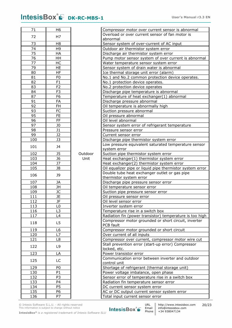
71 H6 Compressor motor over current sensor is abnormal
72 H7 Overload or over current sensor of fan motor is
abnormal
73 H8 Sensor system of over-current of AC input
74 H9 Outdoor air thermistor system error
75 HA Discharge air thermistor system error
76 HH Pump motor sensor system of over current is abnormal
77 HC Water temperature sensor system error
79 HE Sensor system of drain water is abnormal
80 HF Ice thermal storage unit error (alarm)
81 F0 No.1 and No.2 common protection device operates.
82 F1 No.1 protection device operates.
83 F2 No.2 protection device operates
84 F3 Discharge pipe temperature is abnormal
87 F6 Temperature of heat exchanger(1) abnormal
91 FA Discharge pressure abnormal
92 FH Oil temperature is abnormally high
93 FC Suction pressure abnormal
95 FE Oil pressure abnormal
96 FF Oil level abnormal
97 J0 Sensor system error of refrigerant temperature
98 J1 Pressure sensor error
99 J2 Current sensor error
100 J3 Discharge pipe thermistor system error
101 J4 Low pressure equivalent saturated temperature sensor
system error
102 J5 Outdoor Suction pipe thermistor system error
103 J6 Unit Heat exchanger(1) thermistor system error
104 J7 Heat exchanger(2) thermistor system error
105 J8 Oil equalizer pipe or liquid pipe thermistor system error
106 J9 Double tube heat exchanger outlet or gas pipe
thermistor system error
107 JA Discharge pipe pressure sensor error
108 JH Oil temperature sensor error
109 JC Suction pipe pressure sensor error
111 JE Oil pressure sensor error
112 JF Oil level sensor error
113 L0 Inverter system error
116 L3 Temperature rise in a switch box
117 L4 Radiation fin (power transistor) temperature is too high
118 L5 Compressor motor grounded or short circuit, inverter
PCB fault
119 L6 Compressor motor grounded or short circuit
120 L7 Over current of all inputs
121 L8 Compressor over current, compressor motor wire cut
122 L9 Stall prevention error (start-up error) Compressor
locked, etc.
123 LA Power transistor error
125 LC Communication error between inverter and outdoor
control unit
129 P0 Shortage of refrigerant (thermal storage unit)
130 P1 Power voltage imbalance, open phase
132 P3 Sensor error of temperature rise in a switch box
133 P4 Radiation fin temperature sensor error
134 P5 DC current sensor system error
135 P6 AC or DC output current sensor system error
136 P7 Total input current sensor error
DK-RC-MBS-1 User’s Manual r3.3 EN
© Intesis Software S.L.U. - All rights reserved This information is subject to change without notice
IntesisBox® is a registered trademark of Intesis Software SLU
URL
Phone
http://www.intesisbox.com
+34 938047134
21/23
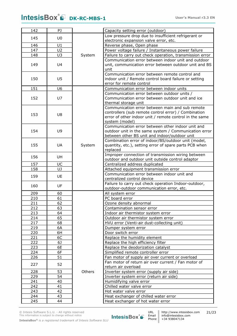
142 PJ Capacity setting error (outdoor)
145 U0 Low pressure drop due to insufficient refrigerant or
electronic expansion valve error, etc.
146 U1 Reverse phase, Open phase
147 U2 Power voltage failure / Instantaneous power failure
148 U3 System Failure to carry out check operation, transmission error
149 U4
Communication error between indoor unit and outdoor
unit, communication error between outdoor unit and BS
unit
150 U5
Communication error between remote control and
indoor unit / Remote control board failure or setting
error for remote control
151 U6 Communication error between indoor units
152 U7
Communication error between outdoor units /
Communication error between outdoor unit and ice
thermal storage unit
153 U8
Communication error between main and sub remote
controllers (sub remote control error) / Combination
error of other indoor unit / remote control in the same
system (model)
154 U9
Communication error between other indoor unit and
outdoor unit in the same system / Communication error
between other BS unit and indoor/outdoor unit
155 UA System
Combination error of indoor/BS/outdoor unit (model,
quantity, etc.), setting error of spare parts PCB when
replaced
156 UH Improper connection of transmission wiring between
outdoor and outdoor unit outside control adaptor
157 UC Centralized address duplicated
158 UJ Attached equipment transmission error
159 UE Communication error between indoor unit and
centralized control device
160 UF Failure to carry out check operation Indoor-outdoor,
outdoor-outdoor communication error, etc.
209 60 All system error
210 61 PC board error
211 62 Ozone density abnormal
212 63 Contamination sensor error
213 64 Indoor air thermistor system error
214 65 Outdoor air thermistor system error
217 68 HVU error (Venti-air dust-collecting unit)
219 6A Dumper system error
220 6H Door switch error
221 6C Replace the humidity element
222 6J Replace the high efficiency filter
223 6E Replace the deodorization catalyst
224 6F Simplified remote controller error
226 51 Fan motor of supply air over current or overload
227 52 Fan motor of return air over current / Fan motor of
return air overload
228 53 Others Inverter system error (supply air side)
229 54 Inverter system error (return air side)
241 40 Humidifying valve error
242 41 Chilled water valve error
243 42 Hot water valve error
244 43 Heat exchanger of chilled water error
245 44 Heat exchanger of hot water error
DK-RC-MBS-1 User’s Manual r3.3 EN
© Intesis Software S.L.U. - All rights reserved This information is subject to change without notice
IntesisBox® is a registered trademark of Intesis Software SLU
URL
Phone
http://www.intesisbox.com
+34 938047134
22/23
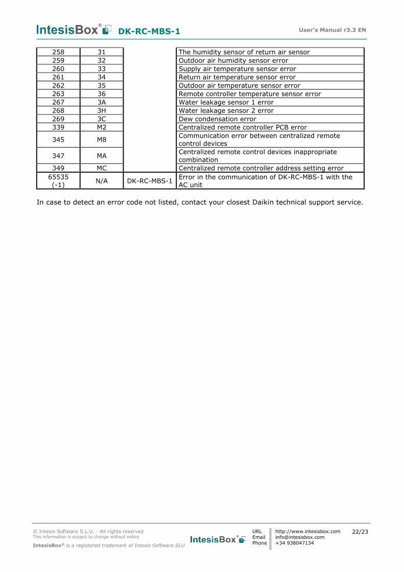
258 31 The humidity sensor of return air sensor
259 32 Outdoor air humidity sensor error
260 33 Supply air temperature sensor error
261 34 Return air temperature sensor error
262 35 Outdoor air temperature sensor error
263 36 Remote controller temperature sensor error
267 3A Water leakage sensor 1 error
268 3H Water leakage sensor 2 error
269 3C Dew condensation error
339 M2 Centralized remote controller PCB error
345 M8 Communication error between centralized remote
control devices
347 MA Centralized remote control devices inappropriate
combination
349 MC Centralized remote controller address setting error
65535
(-1) N/A DK-RC-MBS-1
Error in the communication of DK-RC-MBS-1 with the
AC unit
In case to detect an error code not listed, contact your closest Daikin technical support service.
DK-RC-MBS-1 User’s Manual r3.3 EN
© Intesis Software S.L.U. - All rights reserved This information is subject to change without notice
IntesisBox® is a registered trademark of Intesis Software SLU
URL
Phone
http://www.intesisbox.com
+34 938047134
23/23
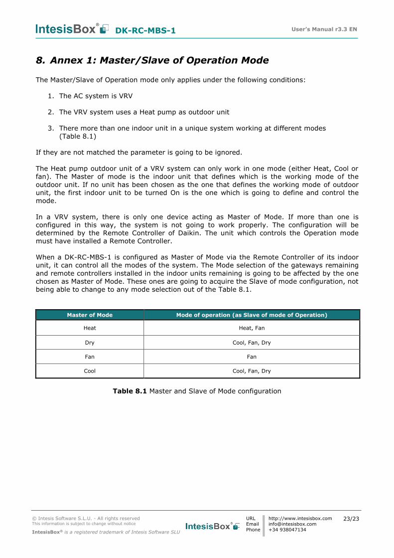
8. Annex 1: Master/Slave of Operation Mode
The Master/Slave of Operation mode only applies under the following conditions:
1. The AC system is VRV
2. The VRV system uses a Heat pump as outdoor unit
3. There more than one indoor unit in a unique system working at different modes
(Table 8.1)
If they are not matched the parameter is going to be ignored.
The Heat pump outdoor unit of a VRV system can only work in one mode (either Heat, Cool or
fan). The Master of mode is the indoor unit that defines which is the working mode of the
outdoor unit. If no unit has been chosen as the one that defines the working mode of outdoor
unit, the first indoor unit to be turned On is the one which is going to define and control the
mode.
In a VRV system, there is only one device acting as Master of Mode. If more than one is
configured in this way, the system is not going to work properly. The configuration will be
determined by the Remote Controller of Daikin. The unit which controls the Operation mode
must have installed a Remote Controller.
When a DK-RC-MBS-1 is configured as Master of Mode via the Remote Controller of its indoor
unit, it can control all the modes of the system. The Mode selection of the gateways remaining
and remote controllers installed in the indoor units remaining is going to be affected by the one
chosen as Master of Mode. These ones are going to acquire the Slave of mode configuration, not
being able to change to any mode selection out of the Table 8.1.
Master of Mode Mode of operation (as Slave of mode of Operation)
Heat Heat, Fan
Dry Cool, Fan, Dry
Fan Fan
Cool Cool, Fan, Dry
Table 8.1 Master and Slave of Mode configuration
Recommended