Embed Size (px)
Citation preview
IntesisBox® ME-AC-MBS-1 v.1.13 User’s Manual rev.8
IntesisBox® ME-AC-MBS-1 v.1.13
MODBUS RTU (RS-485) Interface for Mitsubishi Electric air
conditioners. Compatible with all models of Domestic & Mr.Slim lines.
User Manual
Order Code: ME-AC-MBS-1
IntesisBox® ME-AC-MBS-1 v.1.13 User’s Manual rev.8
© Intesis Software S.L. 2009. All Rights Reserved.
Information in this document is subject to change without notice. No part of this publication
may be reproduced, stored in a retrieval system or transmitted in any form or any means
electronic or mechanical, including photocopying and recording for any purpose other than
the purchaser’s personal use without the written permission of Intesis Software S.L.
Intesis Software S.L. Milà i Fontanals, 1 bis - 1º 08700 Igualada Spain TRADEMARKS All trademarks and tradenames used in this document are acknowledged to be the copyright of their respective holders.
IntesisBox® ME-AC-MBS-1 v.1.13 User’s Manual rev.8
INDEX
1. Presentation ................................................................................................... 4
2. Connection ..................................................................................................... 5
3. Modbus Interface Specification .......................................................................... 6
3.1 Modbus physical layer................................................................................... 6
3.2 Modbus Registers ......................................................................................... 6
3.2.1 Control and status registers ....................................................................... 6
3.2.2 Configuration Registers ............................................................................. 7
3.3 DIP-switch Configuration Interface ................................................................. 8
3.4 Implemented Functions................................................................................. 9
3.5 Configuration of the device............................................................................ 9
3.6 Device LED indicator................................................................................... 10
3.7 RS485 bus. Termination resistors and Fail Safe Biasing mechanism.................. 10
4. Specifications................................................................................................ 12
5. List of supported AC Unit Types....................................................................... 13
6. Available features for each type of AC Unit. ...................................................... 14
7. Error Codes .................................................................................................. 17
IntesisBox® ME-AC-MBS-1 v.1.13 User’s Manual rev.8
1. Presentation
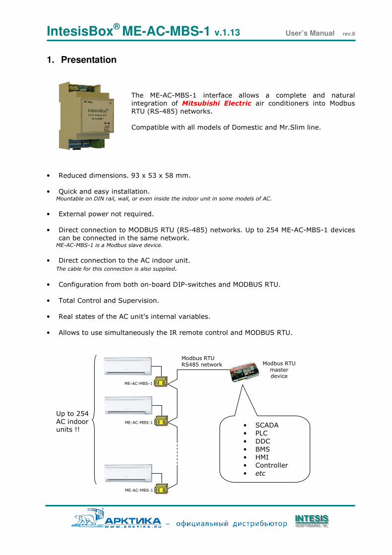
The ME-AC-MBS-1 interface allows a complete and natural
integration of Mitsubishi Electric air conditioners into Modbus
RTU (RS-485) networks.
Compatible with all models of Domestic and Mr.Slim line.
• Reduced dimensions. 93 x 53 x 58 mm.
• Quick and easy installation. Mountable on DIN rail, wall, or even inside the indoor unit in some models of AC.
• External power not required.
• Direct connection to MODBUS RTU (RS-485) networks. Up to 254 ME-AC-MBS-1 devices
can be connected in the same network. ME-AC-MBS-1 is a Modbus slave device.
• Direct connection to the AC indoor unit.
The cable for this connection is also supplied.
• Configuration from both on-board DIP-switches and MODBUS RTU.
• Total Control and Supervision.
• Real states of the AC unit's internal variables.
• Allows to use simultaneously the IR remote control and MODBUS RTU.
Up to 254
AC indoor units !!
Modbus RTU RS485 network
Modbus RTU master device
ME-AC-MBS-1
• SCADA
• PLC
• DDC
• BMS
• HMI
• Controller
• etc
ME-AC-MBS-1
ME-AC-MBS-1
IntesisBox® ME-AC-MBS-1 v.1.13 User’s Manual rev.8
2. Connection
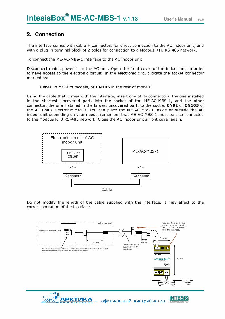
The interface comes with cable + connectors for direct connection to the AC indoor unit, and
with a plug-in terminal block of 2 poles for connection to a Modbus RTU RS-485 network.
To connect the ME-AC-MBS-1 interface to the AC indoor unit:
Disconnect mains power from the AC unit. Open the front cover of the indoor unit in order
to have access to the electronic circuit. In the electronic circuit locate the socket connector
marked as:
CN92 in Mr.Slim models, or CN105 in the rest of models.
Using the cable that comes with the interface, insert one of its connectors, the one installed
in the shortest uncovered part, into the socket of the ME-AC-MBS-1, and the other
connector, the one installed in the largest uncovered part, to the socket CN92 or CN105 of
the AC unit's electronic circuit. You can place the ME-AC-MBS-1 inside or outside the AC
indoor unit depending on your needs, remember that ME-AC-MBS-1 must be also connected
to the Modbus RTU RS-485 network. Close the AC indoor unit's front cover again.
Do not modify the length of the cable supplied with the interface, it may affect to the
correct operation of the interface.
Electronic circuit of AC indoor unit
CN92 or CN105
ME-AC-MBS-1
Connector
Cable
Connector
CN105
or CN92
AC indoor unit
Electronic circuit board
200 mm 40 mm Connection cable
supplied with the interface.
90 mm
CN105 for Domestic line, CN92 for Mr.Slim line. Consult list of models at the end of the document to identify to which line belongs every model.
IntesisBox® ME-AC-MBS-1
Modbus RTU
RS485 Bus
RS485 A B
AC Unit
53 mm
Use this hole to fix the
cable using the staple and screw provided
with the interface.
IntesisBox® ME-AC-MBS-1 v.1.13 User’s Manual rev.8
3. Modbus Interface Specification
3.1 Modbus physical layer
ME-AC-MBS-1 implements a MODBUS RTU (slave) interface, to be connected to an RS-485
line. It performs an 8N1 communication (8 data bits, no parity and 1 stop bit) with several
available baudrates (2400 bps, 9600 bps -default-, 19200 bps and 57600 bps).
3.2 Modbus Registers
All registers are of type “16-bit unsigned Holding Register”, in standard modbus’ big endian
notation.
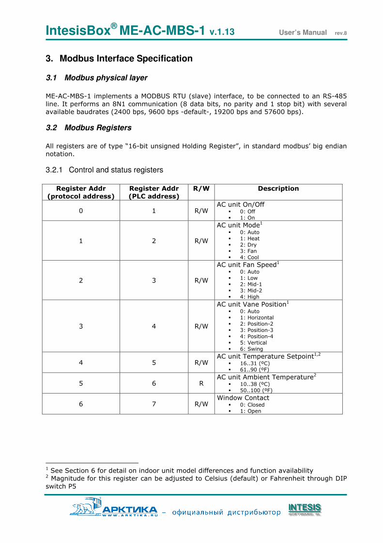
3.2.1 Control and status registers
Register Addr
(protocol address)
Register Addr
(PLC address)
R/W Description
0 1 R/W AC unit On/Off
0: Off 1: On
1 2 R/W
AC unit Mode1 0: Auto 1: Heat 2: Dry 3: Fan 4: Cool
2 3 R/W
AC unit Fan Speed1 0: Auto 1: Low 2: Mid-1 3: Mid-2 4: High
3 4 R/W
AC unit Vane Position1 0: Auto 1: Horizontal 2: Position-2 3: Position-3 4: Position-4 5: Vertical 6: Swing
4 5 R/W AC unit Temperature Setpoint1,2
16..31 (ºC) 61..90 (ºF)
5 6 R AC unit Ambient Temperature2
10..38 (ºC) 50..100 (ºF)
6 7 R/W Window Contact
0: Closed 1: Open
1 See Section 6 for detail on indoor unit model differences and function availability 2 Magnitude for this register can be adjusted to Celsius (default) or Fahrenheit through DIP
switch P5
IntesisBox® ME-AC-MBS-1 v.1.13 User’s Manual rev.8
Register Addr
(protocol address)
Register Addr
(PLC address)
R/W Description
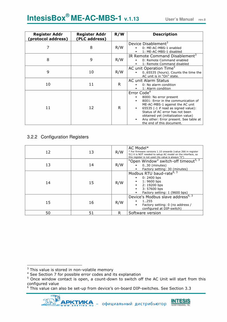
7 8 R/W Device Disablement3
0: ME-AC-MBS-1 enabled 1: ME-AC-MBS-1 disabled
8 9 R/W IR Remote Command Disablement3
0: Remote Command enabled 1: Remote Command disabled
9 10 R/W AC unit Operation Time3
0..65535 (hours). Counts the time the AC unit is in “On” state.
10 11 R AC unit Alarm Status
0: No alarm condition 1: Alarm condition
11 12 R
Error Code4 8000: No error present 8001: Error in the communication of
ME-AC-MBS-1 against the AC unit 65535 (-1 if read as signed value):
Status of AC error has not been obtained yet (initialization value)
Any other: Error present. See table at the end of this document.
3.2.2 Configuration Registers
12 13 R/W AC Model* * For firmware versions 1.10 onwards (value 266 in register
51) it is NOT needed to setup AC model on the interface, so
this register is not used (its value is always “0”)
13 14 R/W “Open Window” switch-off timeout5, 3
0..30 (minutes) Factory setting: 30 (minutes)
14 15 R/W
Modbus RTU baud-rate6, 3 0: 2400 bps 1: 9600 bps 2: 19200 bps 3: 57600 bps Factory setting: 1 (9600 bps)
15 16 R/W
Device's Modbus slave address6, 3 1..255 Factory setting: 0 (no address /
configured at DIP-switch)
50 51 R Software version
3 This value is stored in non-volatile memory 4 See Section 7 for possible error codes and its explanation 5 Once window contact is open, a count-down to switch off the AC Unit will start from this
configured value 6 This value can also be set-up from device’s on-board DIP-switches. See Section 3.3
IntesisBox® ME-AC-MBS-1 v.1.13 User’s Manual rev.8
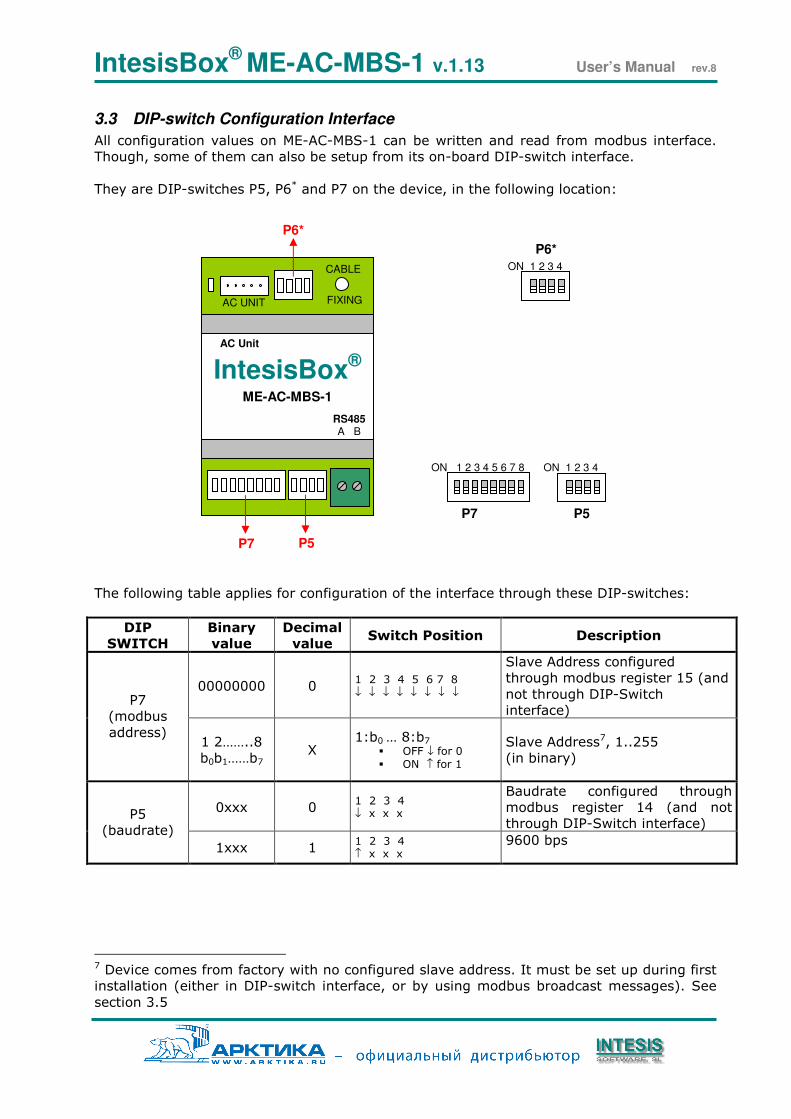
3.3 DIP-switch Configuration Interface
All configuration values on ME-AC-MBS-1 can be written and read from modbus interface.
Though, some of them can also be setup from its on-board DIP-switch interface.
They are DIP-switches P5, P6* and P7 on the device, in the following location:
The following table applies for configuration of the interface through these DIP-switches:
DIP
SWITCH
Binary
value
Decimal
value Switch Position Description
00000000 0 1 2 3 4 5 6 7 8 ↓ ↓ ↓ ↓ ↓ ↓ ↓ ↓
Slave Address configured
through modbus register 15 (and
not through DIP-Switch
interface) P7
(modbus
address) 1 2……..8
b0b1……b7 X
1:b0 … 8:b7
OFF ↓ for 0 ON ↑ for 1
Slave Address7, 1..255
(in binary)
0xxx 0 1 2 3 4 ↓ x x x
Baudrate configured through
modbus register 14 (and not
through DIP-Switch interface) P5
(baudrate)
1xxx 1 1 2 3 4 ↑ x x x
9600 bps
7 Device comes from factory with no configured slave address. It must be set up during first
installation (either in DIP-switch interface, or by using modbus broadcast messages). See
section 3.5
AC UNIT FIXING
CABLE
IntesisBox® ME-AC-MBS-1
RS485 A B
AC Unit
P7 P5
P6*
ON 1 2 3 4
P6*
ON 1 2 3 4
P5
ON 1 2 3 4 5 6 7 8
P7
IntesisBox® ME-AC-MBS-1 v.1.13 User’s Manual rev.8
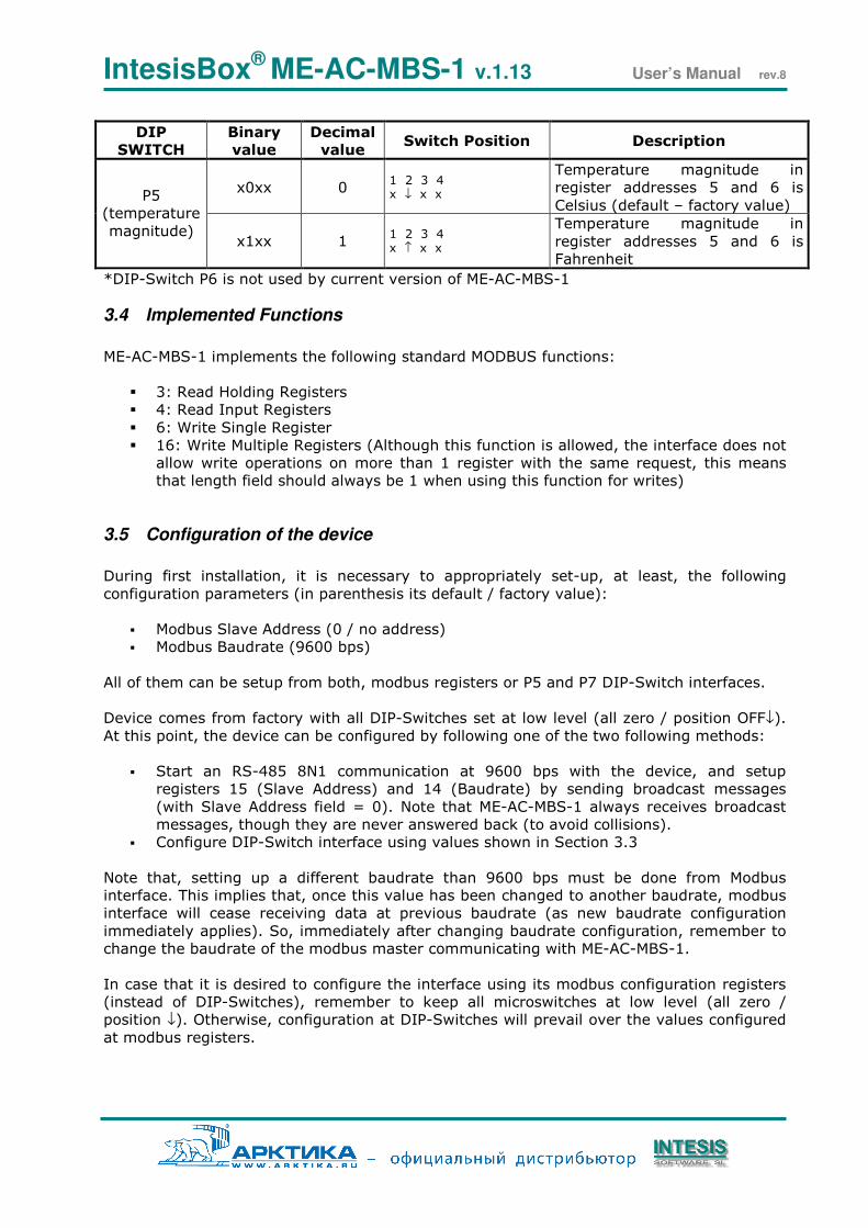
DIP
SWITCH
Binary
value
Decimal
value Switch Position Description
x0xx 0 1 2 3 4 x ↓ x x
Temperature magnitude in
register addresses 5 and 6 is
Celsius (default – factory value) P5
(temperature
magnitude) x1xx 1
1 2 3 4 x ↑ x x
Temperature magnitude in
register addresses 5 and 6 is
Fahrenheit
*DIP-Switch P6 is not used by current version of ME-AC-MBS-1
3.4 Implemented Functions
ME-AC-MBS-1 implements the following standard MODBUS functions:
3: Read Holding Registers
4: Read Input Registers
6: Write Single Register
16: Write Multiple Registers (Although this function is allowed, the interface does not
allow write operations on more than 1 register with the same request, this means
that length field should always be 1 when using this function for writes)
3.5 Configuration of the device
During first installation, it is necessary to appropriately set-up, at least, the following
configuration parameters (in parenthesis its default / factory value):
Modbus Slave Address (0 / no address)
Modbus Baudrate (9600 bps)
All of them can be setup from both, modbus registers or P5 and P7 DIP-Switch interfaces.
Device comes from factory with all DIP-Switches set at low level (all zero / position OFF↓).
At this point, the device can be configured by following one of the two following methods:
Start an RS-485 8N1 communication at 9600 bps with the device, and setup
registers 15 (Slave Address) and 14 (Baudrate) by sending broadcast messages
(with Slave Address field = 0). Note that ME-AC-MBS-1 always receives broadcast
messages, though they are never answered back (to avoid collisions).
Configure DIP-Switch interface using values shown in Section 3.3
Note that, setting up a different baudrate than 9600 bps must be done from Modbus
interface. This implies that, once this value has been changed to another baudrate, modbus
interface will cease receiving data at previous baudrate (as new baudrate configuration
immediately applies). So, immediately after changing baudrate configuration, remember to
change the baudrate of the modbus master communicating with ME-AC-MBS-1.
In case that it is desired to configure the interface using its modbus configuration registers
(instead of DIP-Switches), remember to keep all microswitches at low level (all zero /
position ↓). Otherwise, configuration at DIP-Switches will prevail over the values configured
at modbus registers.
IntesisBox® ME-AC-MBS-1 v.1.13 User’s Manual rev.8
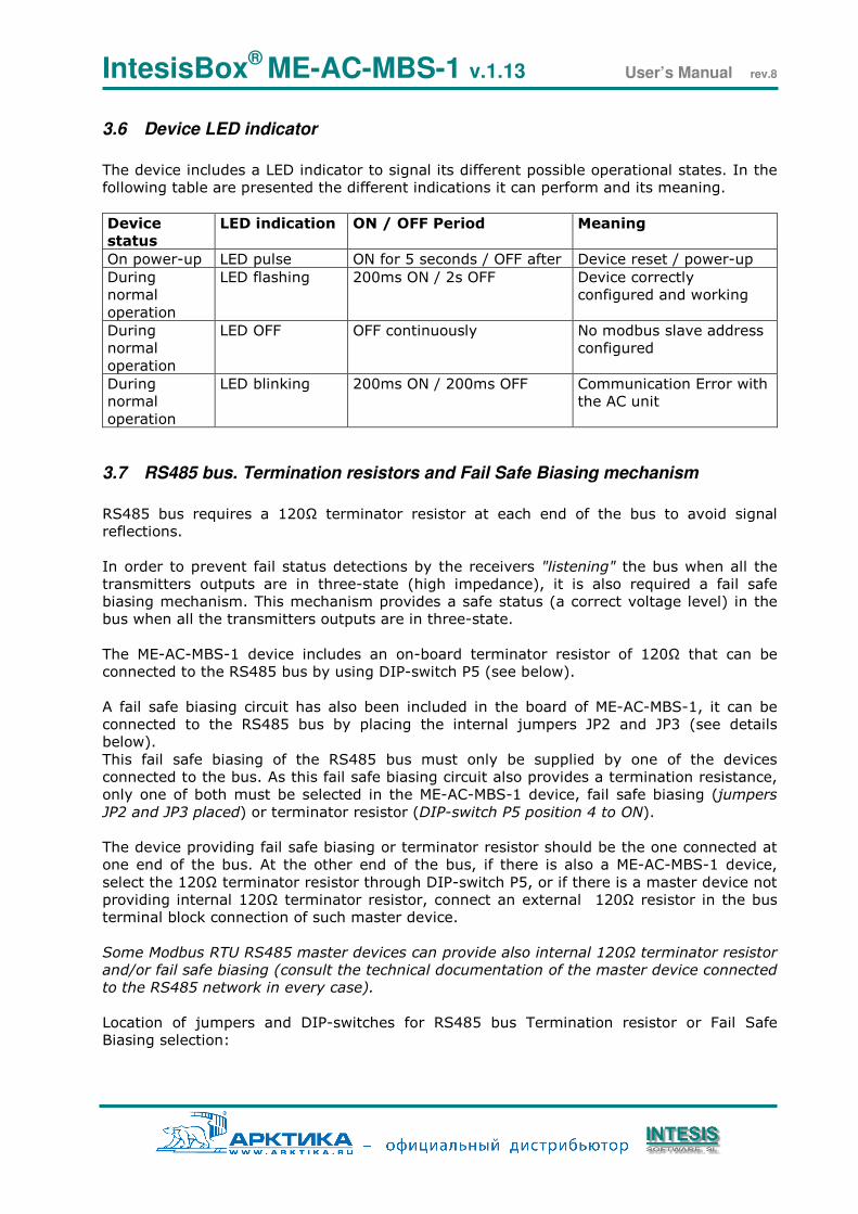
3.6 Device LED indicator
The device includes a LED indicator to signal its different possible operational states. In the
following table are presented the different indications it can perform and its meaning.
Device
status
LED indication ON / OFF Period Meaning
On power-up LED pulse ON for 5 seconds / OFF after Device reset / power-up
During
normal
operation
LED flashing 200ms ON / 2s OFF
Device correctly
configured and working
During
normal
operation
LED OFF OFF continuously No modbus slave address
configured
During
normal
operation
LED blinking
200ms ON / 200ms OFF
Communication Error with
the AC unit
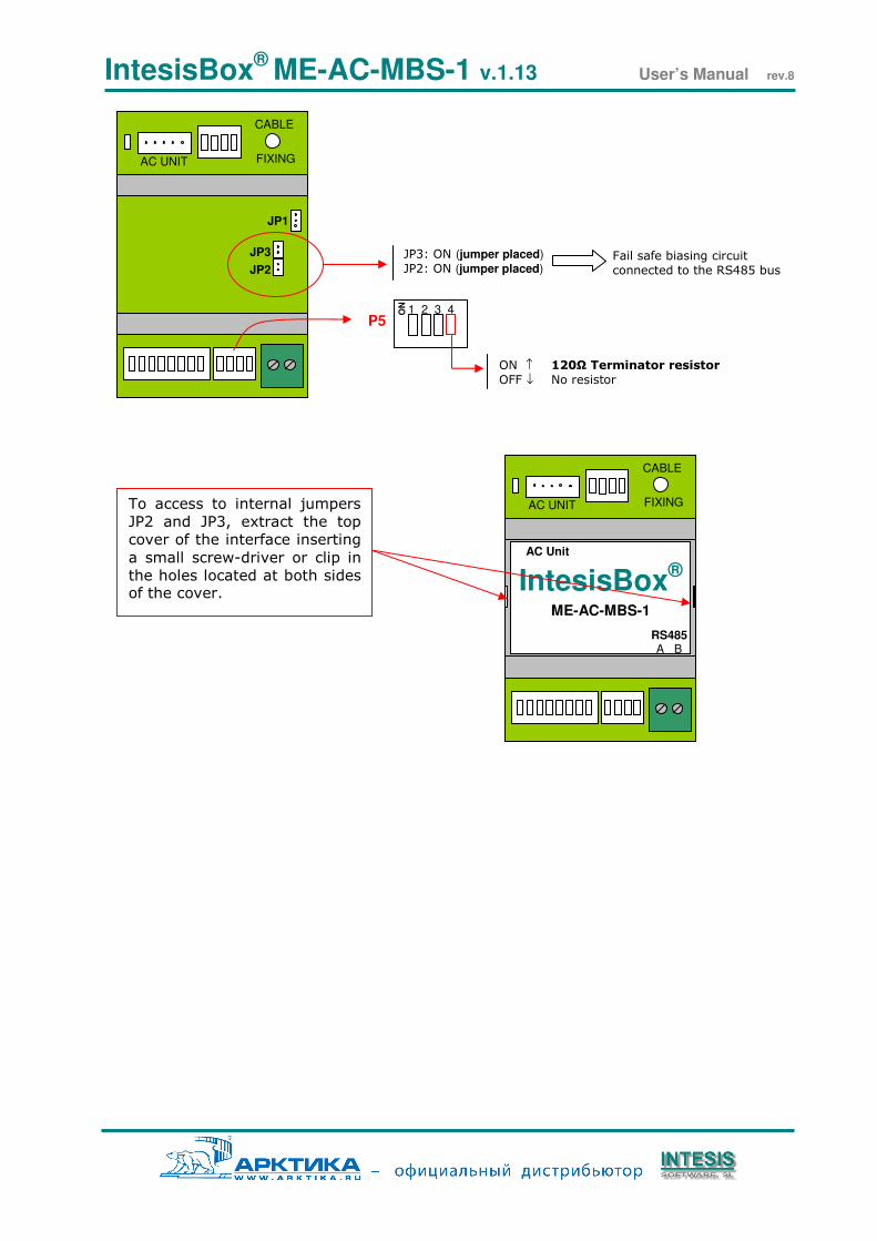
3.7 RS485 bus. Termination resistors and Fail Safe Biasing mechanism
RS485 bus requires a 120Ω terminator resistor at each end of the bus to avoid signal
reflections.
In order to prevent fail status detections by the receivers "listening" the bus when all the
transmitters outputs are in three-state (high impedance), it is also required a fail safe
biasing mechanism. This mechanism provides a safe status (a correct voltage level) in the
bus when all the transmitters outputs are in three-state.
The ME-AC-MBS-1 device includes an on-board terminator resistor of 120Ω that can be
connected to the RS485 bus by using DIP-switch P5 (see below).
A fail safe biasing circuit has also been included in the board of ME-AC-MBS-1, it can be
connected to the RS485 bus by placing the internal jumpers JP2 and JP3 (see details
below).
This fail safe biasing of the RS485 bus must only be supplied by one of the devices
connected to the bus. As this fail safe biasing circuit also provides a termination resistance,
only one of both must be selected in the ME-AC-MBS-1 device, fail safe biasing (jumpers
JP2 and JP3 placed) or terminator resistor (DIP-switch P5 position 4 to ON).
The device providing fail safe biasing or terminator resistor should be the one connected at
one end of the bus. At the other end of the bus, if there is also a ME-AC-MBS-1 device,
select the 120Ω terminator resistor through DIP-switch P5, or if there is a master device not
providing internal 120Ω terminator resistor, connect an external 120Ω resistor in the bus
terminal block connection of such master device.
Some Modbus RTU RS485 master devices can provide also internal 120Ω terminator resistor
and/or fail safe biasing (consult the technical documentation of the master device connected
to the RS485 network in every case).
Location of jumpers and DIP-switches for RS485 bus Termination resistor or Fail Safe
Biasing selection:
IntesisBox® ME-AC-MBS-1 v.1.13 User’s Manual rev.8
AC UNIT FIXING
CABLE
JP1
JP3
JP2
JP3: ON (jumper placed) JP2: ON (jumper placed)
Fail safe biasing circuit
connected to the RS485 bus
AC UNIT FIXING
CABLE
IntesisBox® ME-AC-MBS-1
RS485 A B
AC Unit
To access to internal jumpers
JP2 and JP3, extract the top
cover of the interface inserting
a small screw-driver or clip in
the holes located at both sides of the cover.
ON ↑ 120Ω Terminator resistor OFF ↓ No resistor
P5 1 2 3 4 O
N
IntesisBox® ME-AC-MBS-1 v.1.13 User’s Manual rev.8
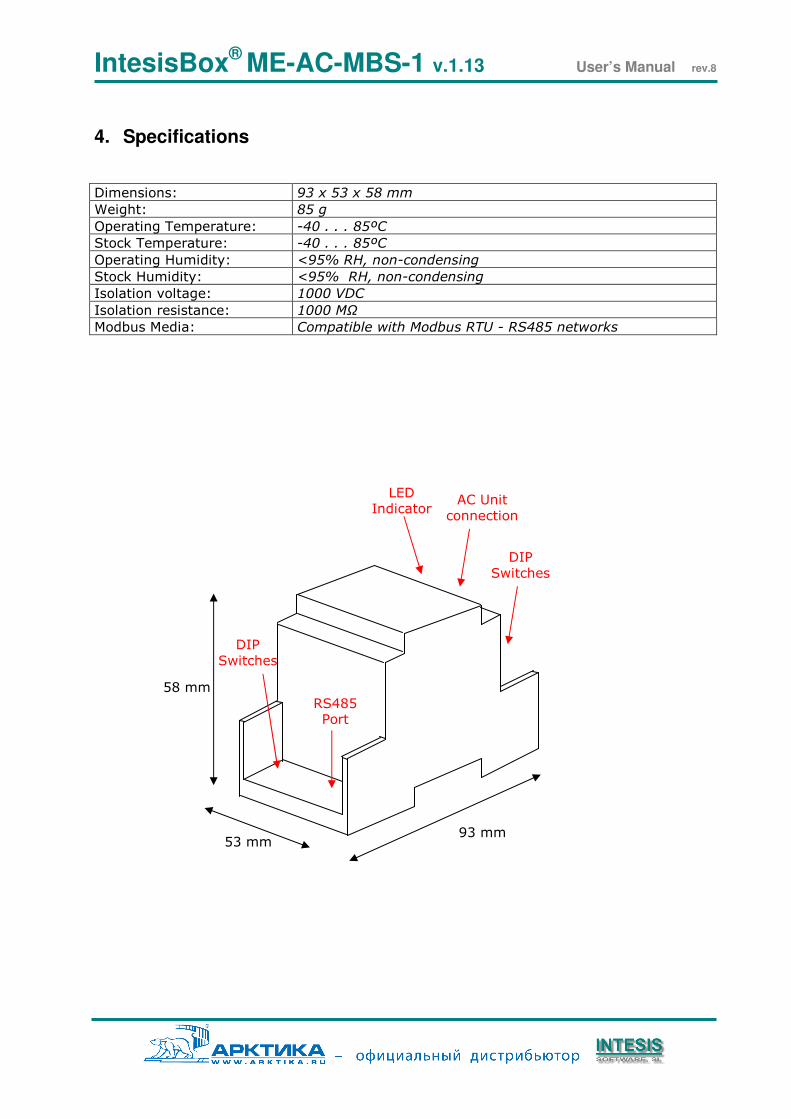
4. Specifications
Dimensions: 93 x 53 x 58 mm
Weight: 85 g
Operating Temperature: -40 . . . 85ºC
Stock Temperature: -40 . . . 85ºC
Operating Humidity: <95% RH, non-condensing
Stock Humidity: <95% RH, non-condensing
Isolation voltage: 1000 VDC
Isolation resistance: 1000 MΩ
Modbus Media: Compatible with Modbus RTU - RS485 networks
53 mm 93 mm
58 mm
RS485 Port
AC Unit connection
DIP Switches
DIP Switches
LED Indicator
IntesisBox® ME-AC-MBS-1 v.1.13 User’s Manual rev.8
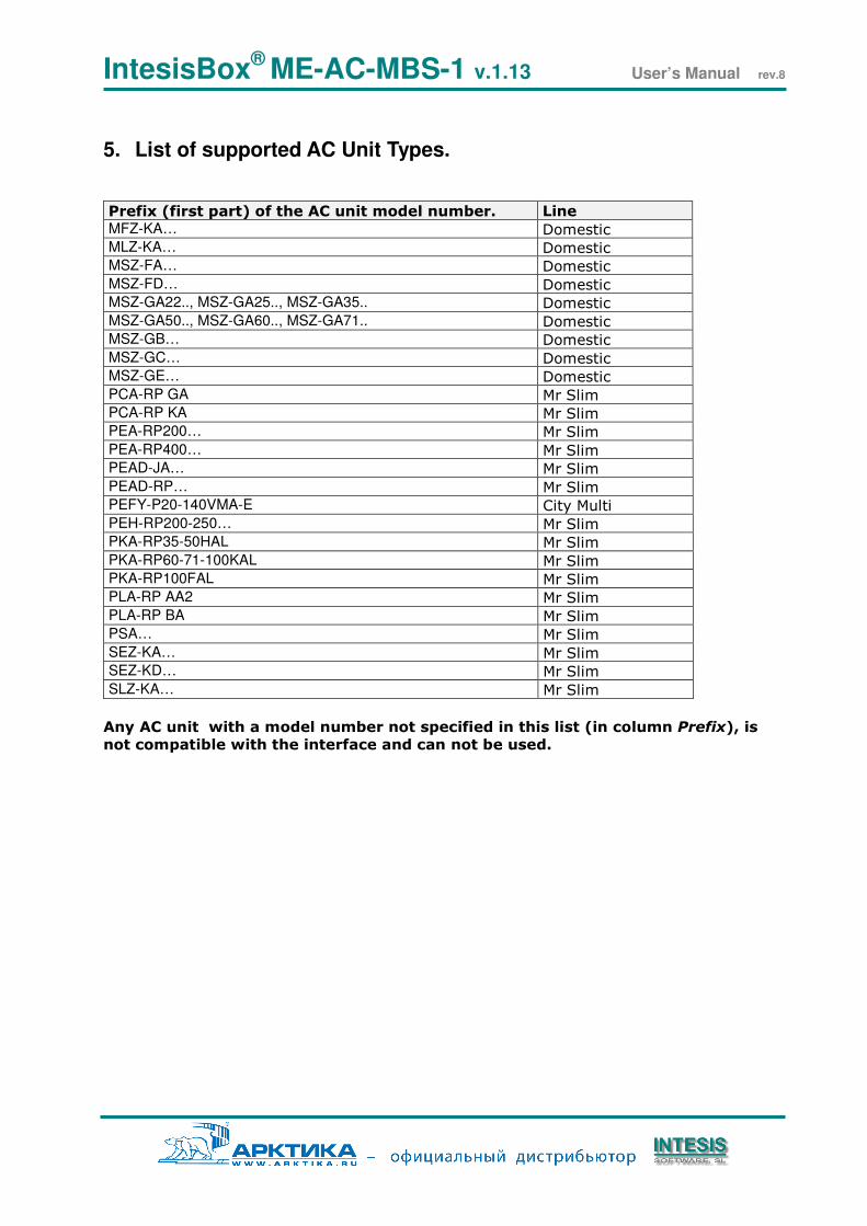
5. List of supported AC Unit Types.
Any AC unit with a model number not specified in this list (in column Prefix), is
not compatible with the interface and can not be used.
Prefix (first part) of the AC unit model number. Line MFZ-KA… Domestic MLZ-KA… Domestic MSZ-FA… Domestic MSZ-FD… Domestic MSZ-GA22.., MSZ-GA25.., MSZ-GA35.. Domestic MSZ-GA50.., MSZ-GA60.., MSZ-GA71.. Domestic MSZ-GB… Domestic MSZ-GC… Domestic MSZ-GE… Domestic PCA-RP GA Mr Slim PCA-RP KA Mr Slim PEA-RP200… Mr Slim PEA-RP400… Mr Slim PEAD-JA… Mr Slim PEAD-RP… Mr Slim PEFY-P20-140VMA-E City Multi PEH-RP200-250… Mr Slim PKA-RP35-50HAL Mr Slim PKA-RP60-71-100KAL Mr Slim PKA-RP100FAL Mr Slim PLA-RP AA2 Mr Slim PLA-RP BA Mr Slim PSA… Mr Slim SEZ-KA… Mr Slim SEZ-KD… Mr Slim SLZ-KA… Mr Slim
IntesisBox® ME-AC-MBS-1 v.1.13 User’s Manual rev.8
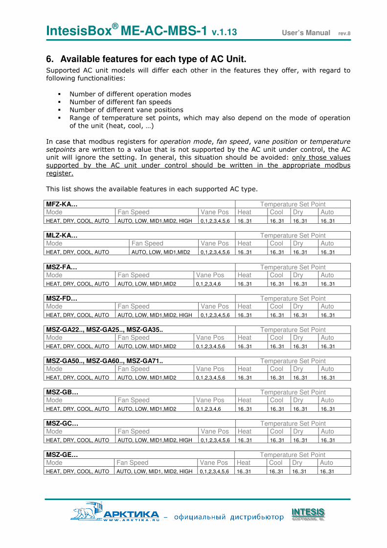
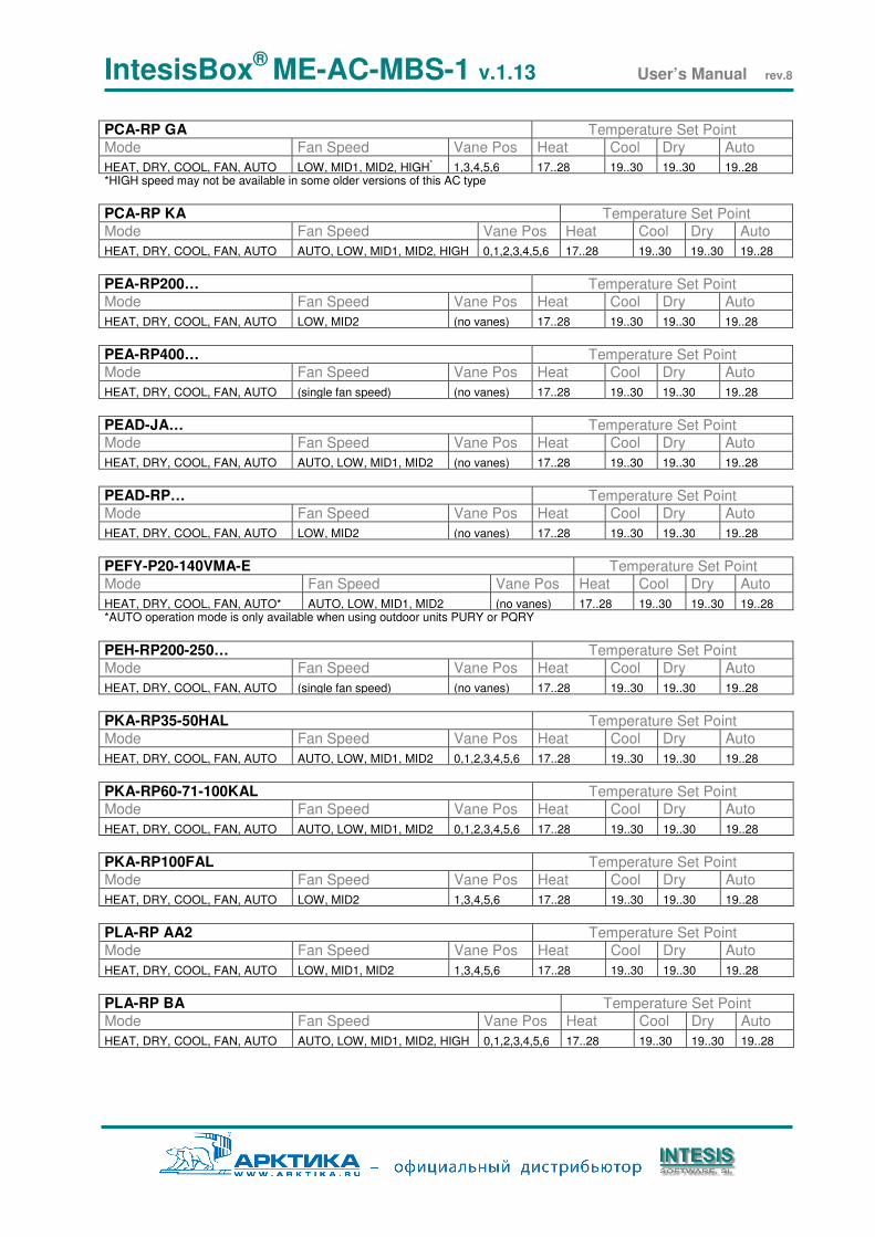
6. Available features for each type of AC Unit. Supported AC unit models will differ each other in the features they offer, with regard to
following functionalities:
Number of different operation modes
Number of different fan speeds
Number of different vane positions
Range of temperature set points, which may also depend on the mode of operation
of the unit (heat, cool, …)
In case that modbus registers for operation mode, fan speed, vane position or temperature
setpoints are written to a value that is not supported by the AC unit under control, the AC
unit will ignore the setting. In general, this situation should be avoided: only those values
supported by the AC unit under control should be written in the appropriate modbus
register.
This list shows the available features in each supported AC type. MFZ-KA… Temperature Set Point
Mode Fan Speed Vane Pos Heat Cool Dry Auto
HEAT, DRY, COOL, AUTO AUTO, LOW, MID1,MID2, HIGH 0,1,2,3,4,5,6 16..31 16..31 16..31 16..31
MLZ-KA… Temperature Set Point
Mode Fan Speed Vane Pos Heat Cool Dry Auto
HEAT, DRY, COOL, AUTO AUTO, LOW, MID1,MID2 0,1,2,3,4,5,6 16..31 16..31 16..31 16..31
MSZ-FA… Temperature Set Point
Mode Fan Speed Vane Pos Heat Cool Dry Auto
HEAT, DRY, COOL, AUTO AUTO, LOW, MID1,MID2 0,1,2,3,4,6 16..31 16..31 16..31 16..31
MSZ-FD… Temperature Set Point
Mode Fan Speed Vane Pos Heat Cool Dry Auto
HEAT, DRY, COOL, AUTO AUTO, LOW, MID1,MID2, HIGH 0,1,2,3,4,5,6 16..31 16..31 16..31 16..31
MSZ-GA22.., MSZ-GA25.., MSZ-GA35.. Temperature Set Point
Mode Fan Speed Vane Pos Heat Cool Dry Auto
HEAT, DRY, COOL, AUTO AUTO, LOW, MID1,MID2 0,1,2,3,4,5,6 16..31 16..31 16..31 16..31
MSZ-GA50.., MSZ-GA60.., MSZ-GA71.. Temperature Set Point
Mode Fan Speed Vane Pos Heat Cool Dry Auto
HEAT, DRY, COOL, AUTO AUTO, LOW, MID1,MID2 0,1,2,3,4,5,6 16..31 16..31 16..31 16..31
MSZ-GB… Temperature Set Point
Mode Fan Speed Vane Pos Heat Cool Dry Auto
HEAT, DRY, COOL, AUTO AUTO, LOW, MID1,MID2 0,1,2,3,4,6 16..31 16..31 16..31 16..31
MSZ-GC… Temperature Set Point
Mode Fan Speed Vane Pos Heat Cool Dry Auto
HEAT, DRY, COOL, AUTO AUTO, LOW, MID1,MID2, HIGH 0,1,2,3,4,5,6 16..31 16..31 16..31 16..31
MSZ-GE… Temperature Set Point
Mode Fan Speed Vane Pos Heat Cool Dry Auto
HEAT, DRY, COOL, AUTO AUTO, LOW, MID1, MID2, HIGH 0,1,2,3,4,5,6 16..31 16..31 16..31 16..31
IntesisBox® ME-AC-MBS-1 v.1.13 User’s Manual rev.8
PCA-RP GA Temperature Set Point
Mode Fan Speed Vane Pos Heat Cool Dry Auto
HEAT, DRY, COOL, FAN, AUTO LOW, MID1, MID2, HIGH* 1,3,4,5,6 17..28 19..30 19..30 19..28
*HIGH speed may not be available in some older versions of this AC type
PCA-RP KA Temperature Set Point
Mode Fan Speed Vane Pos Heat Cool Dry Auto
HEAT, DRY, COOL, FAN, AUTO AUTO, LOW, MID1, MID2, HIGH 0,1,2,3,4,5,6 17..28 19..30 19..30 19..28
PEA-RP200… Temperature Set Point
Mode Fan Speed Vane Pos Heat Cool Dry Auto
HEAT, DRY, COOL, FAN, AUTO LOW, MID2 (no vanes) 17..28 19..30 19..30 19..28
PEA-RP400… Temperature Set Point
Mode Fan Speed Vane Pos Heat Cool Dry Auto
HEAT, DRY, COOL, FAN, AUTO (single fan speed) (no vanes) 17..28 19..30 19..30 19..28
PEAD-JA… Temperature Set Point
Mode Fan Speed Vane Pos Heat Cool Dry Auto
HEAT, DRY, COOL, FAN, AUTO AUTO, LOW, MID1, MID2 (no vanes) 17..28 19..30 19..30 19..28
PEAD-RP… Temperature Set Point
Mode Fan Speed Vane Pos Heat Cool Dry Auto
HEAT, DRY, COOL, FAN, AUTO LOW, MID2 (no vanes) 17..28 19..30 19..30 19..28
PEFY-P20-140VMA-E Temperature Set Point
Mode Fan Speed Vane Pos Heat Cool Dry Auto
HEAT, DRY, COOL, FAN, AUTO* AUTO, LOW, MID1, MID2 (no vanes) 17..28 19..30 19..30 19..28 *AUTO operation mode is only available when using outdoor units PURY or PQRY
PEH-RP200-250… Temperature Set Point
Mode Fan Speed Vane Pos Heat Cool Dry Auto
HEAT, DRY, COOL, FAN, AUTO (single fan speed) (no vanes) 17..28 19..30 19..30 19..28
PKA-RP35-50HAL Temperature Set Point
Mode Fan Speed Vane Pos Heat Cool Dry Auto
HEAT, DRY, COOL, FAN, AUTO AUTO, LOW, MID1, MID2 0,1,2,3,4,5,6 17..28 19..30 19..30 19..28
PKA-RP60-71-100KAL Temperature Set Point
Mode Fan Speed Vane Pos Heat Cool Dry Auto
HEAT, DRY, COOL, FAN, AUTO AUTO, LOW, MID1, MID2 0,1,2,3,4,5,6 17..28 19..30 19..30 19..28
PKA-RP100FAL Temperature Set Point
Mode Fan Speed Vane Pos Heat Cool Dry Auto
HEAT, DRY, COOL, FAN, AUTO LOW, MID2 1,3,4,5,6 17..28 19..30 19..30 19..28
PLA-RP AA2 Temperature Set Point
Mode Fan Speed Vane Pos Heat Cool Dry Auto
HEAT, DRY, COOL, FAN, AUTO LOW, MID1, MID2 1,3,4,5,6 17..28 19..30 19..30 19..28
PLA-RP BA Temperature Set Point
Mode Fan Speed Vane Pos Heat Cool Dry Auto
HEAT, DRY, COOL, FAN, AUTO AUTO, LOW, MID1, MID2, HIGH 0,1,2,3,4,5,6 17..28 19..30 19..30 19..28
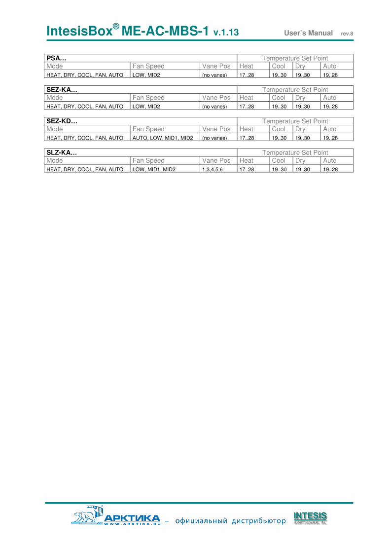
IntesisBox® ME-AC-MBS-1 v.1.13 User’s Manual rev.8
PSA… Temperature Set Point
Mode Fan Speed Vane Pos Heat Cool Dry Auto
HEAT, DRY, COOL, FAN, AUTO LOW, MID2 (no vanes) 17..28 19..30 19..30 19..28
SEZ-KA… Temperature Set Point
Mode Fan Speed Vane Pos Heat Cool Dry Auto
HEAT, DRY, COOL, FAN, AUTO LOW, MID2 (no vanes) 17..28 19..30 19..30 19..28
SEZ-KD… Temperature Set Point
Mode Fan Speed Vane Pos Heat Cool Dry Auto
HEAT, DRY, COOL, FAN, AUTO AUTO, LOW, MID1, MID2 (no vanes) 17..28 19..30 19..30 19..28
SLZ-KA… Temperature Set Point
Mode Fan Speed Vane Pos Heat Cool Dry Auto
HEAT, DRY, COOL, FAN, AUTO LOW, MID1, MID2 1,3,4,5,6 17..28 19..30 19..30 19..28
IntesisBox® ME-AC-MBS-1 v.1.13 User’s Manual rev.8
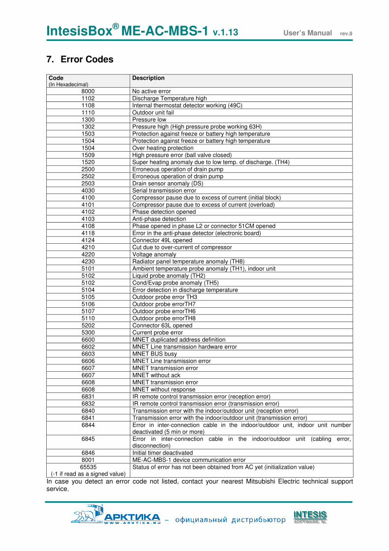
7. Error Codes Code (In Hexadecimal)
Description
8000 No active error
1102 Discharge Temperature high 1108 Internal thermostat detector working (49C)
1110 Outdoor unit fail 1300 Pressure low 1302 Pressure high (High pressure probe working 63H)
1503 Protection against freeze or battery high temperature 1504 Protection against freeze or battery high temperature
1504 Over heating protection 1509 High pressure error (ball valve closed) 1520 Super heating anomaly due to low temp. of discharge. (TH4)
2500 Erroneous operation of drain pump 2502 Erroneous operation of drain pump
2503 Drain sensor anomaly (DS) 4030 Serial transmission error 4100 Compressor pause due to excess of current (initial block)
4101 Compressor pause due to excess of current (overload) 4102 Phase detection opened
4103 Anti-phase detection 4108 Phase opened in phase L2 or connector 51CM opened
4118 Error in the anti-phase detector (electronic board) 4124 Connector 49L opened 4210 Cut due to over-current of compressor
4220 Voltage anomaly 4230 Radiator panel temperature anomaly (TH8)
5101 Ambient temperature probe anomaly (TH1), indoor unit 5102 Liquid probe anomaly (TH2) 5102 Cond/Evap probe anomaly (TH5)
5104 Error detection in discharge temperature 5105 Outdoor probe error TH3
5106 Outdoor probe errorTH7 5107 Outdoor probe errorTH6 5110 Outdoor probe errorTH8
5202 Connector 63L opened 5300 Current probe error
6600 MNET duplicated address definition 6602 MNET Line transmission hardware error 6603 MNET BUS busy
6606 MNET Line transmission error 6607 MNET transmission error
6607 MNET without ack 6608 MNET transmission error
6608 MNET without response 6831 IR remote control transmission error (reception error) 6832 IR remote control transmission error (transmission error)
6840 Transmission error with the indoor/outdoor unit (reception error) 6841 Transmission error with the indoor/outdoor unit (transmission error)
6844 Error in inter-connection cable in the indoor/outdoor unit, indoor unit number deactivated (5 min or more)
6845 Error in inter-connection cable in the indoor/outdoor unit (cabling error, disconnection)
6846 Initial timer deactivated 8001 ME-AC-MBS-1 device communication error
65535 (-1 if read as a signed value)
Status of error has not been obtained from AC yet (initialization value)
In case you detect an error code not listed, contact your nearest Mitsubishi Electric technical support service.