Intermediate Temperature Proton Conducting Fuel Cells for
Transportation Applications
ARPA-E Project (2012 Open)Award No. DE-AR0000314
Project Start: Feb. 2013Completed Q10
S. Elangovan (Ceramatec)Nilesh Dale (Nissan North America)
R. Mukundan, M. Wilson, C. Kreller, Y.S. Kim, K.S. Lee (LANL)
1
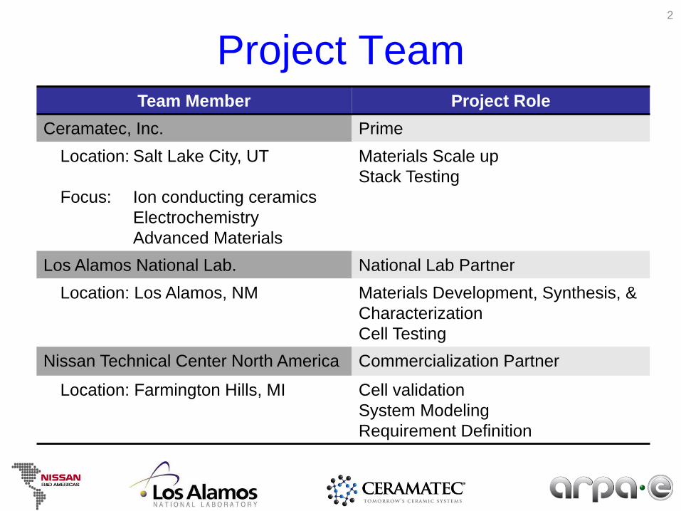
Project TeamTeam Member Project Role
Ceramatec, Inc. PrimeLocation: Salt Lake City, UT
Focus: Ion conducting ceramicsElectrochemistryAdvanced Materials
Materials Scale upStack Testing
Los Alamos National Lab. National Lab PartnerLocation: Los Alamos, NM Materials Development, Synthesis, &
CharacterizationCell Testing
Nissan Technical Center North America Commercialization Partner
Location: Farmington Hills, MI Cell validationSystem ModelingRequirement Definition
2
Project Objectives
• Develop a proton conducting fuel cell based on Tin Pyrophosphate (TPP) that operates at 200 – 250 °C Mid-Temp and Low RH will simplify the
Balance of Plant in the system. This simplification will reduce significant
portion of the Balance of Plant cost.
3
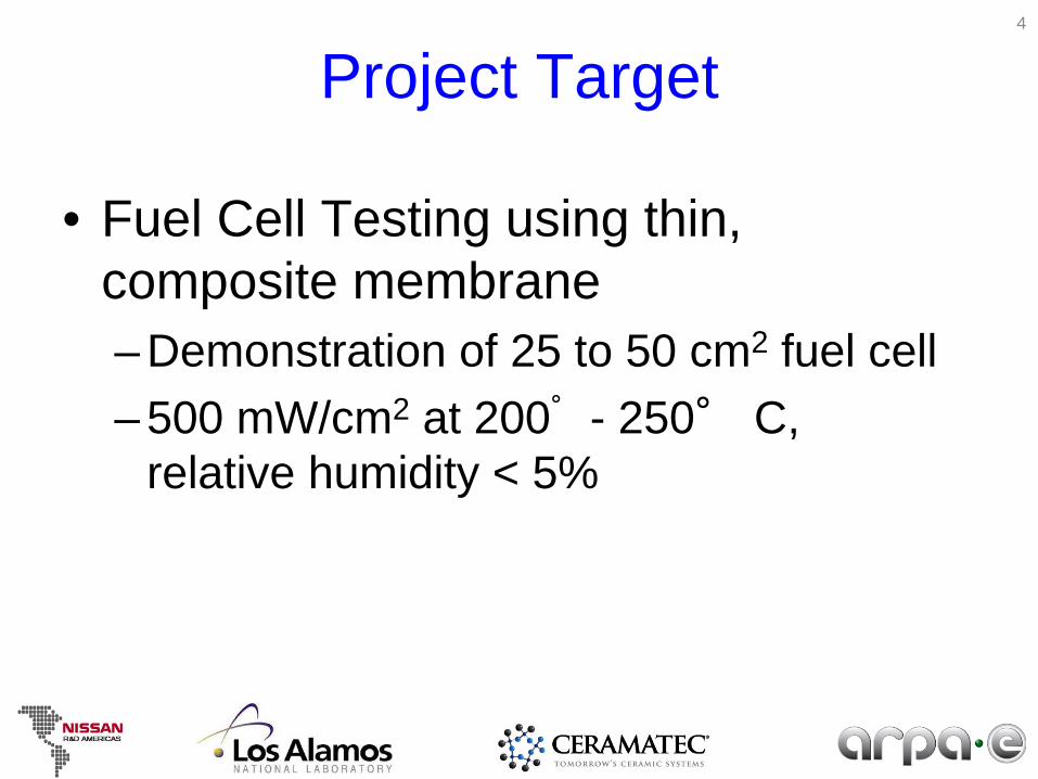
Project Target
• Fuel Cell Testing using thin, composite membrane– Demonstration of 25 to 50 cm2 fuel cell – 500 mW/cm2 at 200° - 250° C,
relative humidity < 5%
4
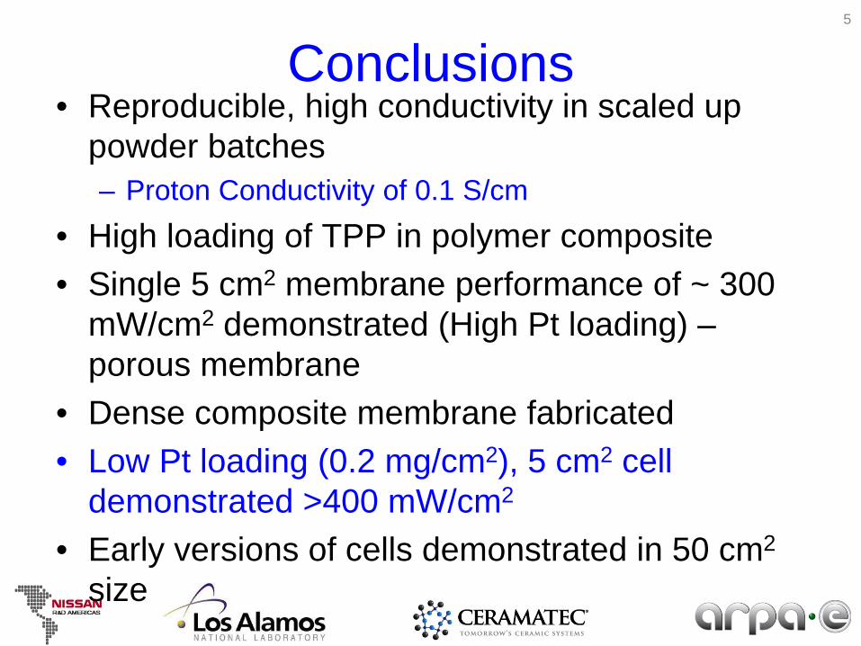
Conclusions• Reproducible, high conductivity in scaled up
powder batches– Proton Conductivity of 0.1 S/cm
• High loading of TPP in polymer composite• Single 5 cm2 membrane performance of ~ 300
mW/cm2 demonstrated (High Pt loading) –porous membrane
• Dense composite membrane fabricated• Low Pt loading (0.2 mg/cm2), 5 cm2 cell
demonstrated >400 mW/cm2
• Early versions of cells demonstrated in 50 cm2
size
5

MOTIVATION
6

7
??????
Inverter
Coaxial motor with reduction gear
BOP system
FC stack H2 Cylinder
Compact Li-ionBattery
ElectricityHydrogen
Radiator Humidification Compressor-Expander Unit H2 Purification Coolant
Possible Cost Saving
Mid-Temperature and Low Humidity Operation Benefits for the Fuel Cell System
Mid temperature operation can lower the FC system cost by simplifying the Balance of Plant (BOP) 7
8
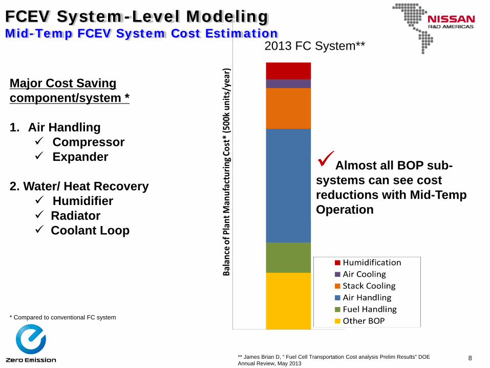
FCEV System-Level ModelingMid-Temp FCEV System Cost Estimation
Almost all BOP sub-systems can see cost reductions with Mid-Temp Operation
2013 FC System**
Major Cost Saving component/system *
1. Air Handling Compressor Expander
2. Water/ Heat Recovery Humidifier Radiator Coolant Loop
* Compared to conventional FC system
** James Brian D, “ Fuel Cell Transportation Cost analysis Prelim Results” DOE Annual Review, May 2013
9
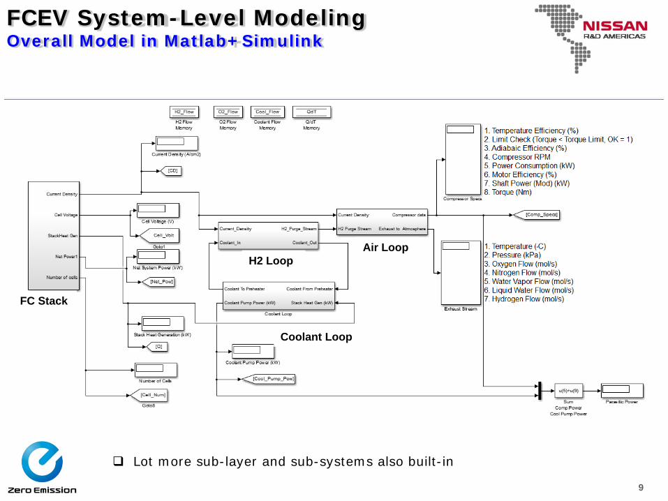
FCEV System-Level ModelingOverall Model in Matlab+Simulink
Lot more sub-layer and sub-systems also built-in
FC Stack
H2 LoopAir Loop
Coolant Loop
10
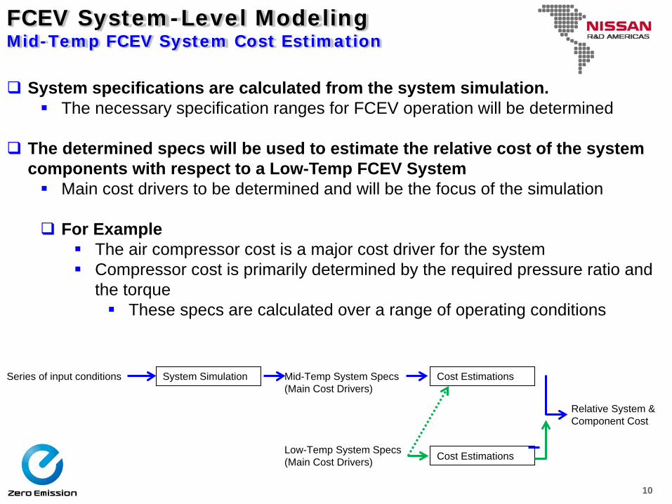
FCEV System-Level ModelingMid-Temp FCEV System Cost Estimation
System specifications are calculated from the system simulation. The necessary specification ranges for FCEV operation will be determined
The determined specs will be used to estimate the relative cost of the system components with respect to a Low-Temp FCEV System Main cost drivers to be determined and will be the focus of the simulation
For Example The air compressor cost is a major cost driver for the system Compressor cost is primarily determined by the required pressure ratio and
the torque These specs are calculated over a range of operating conditions
Series of input conditions System Simulation Mid-Temp System Specs(Main Cost Drivers)
Cost Estimations
Relative System & Component Cost
Low-Temp System Specs(Main Cost Drivers) Cost Estimations
11
MEMBRANE MATERIAL
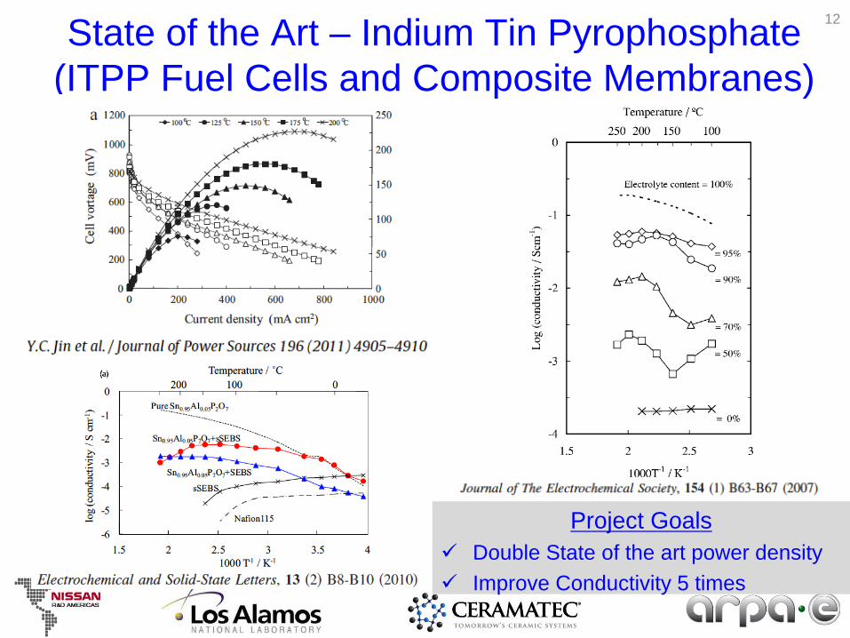
State of the Art – Indium Tin Pyrophosphate (ITPP Fuel Cells and Composite Membranes)
Project Goals Double State of the art power density Improve Conductivity 5 times
12
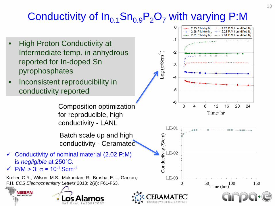
Conductivity of In0.1Sn0.9P2O7 with varying P:M
• High Proton Conductivity at Intermediate temp. in anhydrous reported for In-doped Snpyrophosphates
• Inconsistent reproducibility in conductivity reported
1.E-03
1.E-02
1.E-01
0 50 100 150
Con
duct
ivity
(S/c
m)
Time (hrs)
Composition optimization for reproducible, high conductivity - LANL
Batch scale up and high conductivity - Ceramatec
Conductivity of nominal material (2.02 P:M) is negligible at 250˚C.
P/M > 3; σ ≈ 10-1 Scm-1
Kreller, C.R.; Wilson, M.S.; Mukundan, R.; Brosha, E.L.; Garzon, F.H. ECS Electrochemistry Letters 2013; 2(9): F61-F63.
13
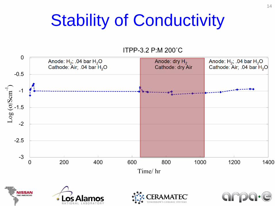
Stability of Conductivity14

SINGLE CELL TESTING
15
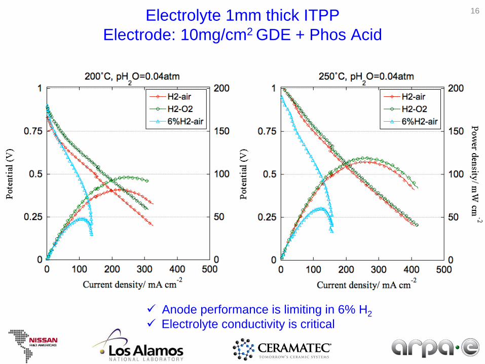
Electrolyte 1mm thick ITPPElectrode: 10mg/cm2 GDE + Phos Acid
Anode performance is limiting in 6% H2 Electrolyte conductivity is critical
16
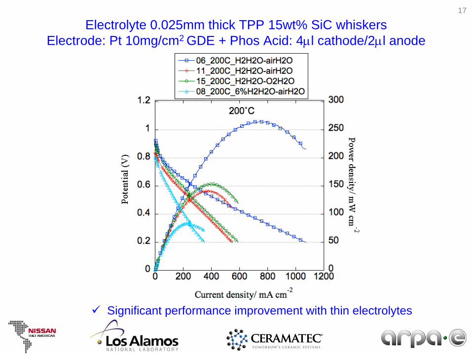
Electrolyte 0.025mm thick TPP 15wt% SiC whiskersElectrode: Pt 10mg/cm2 GDE + Phos Acid: 4µl cathode/2µl anode
Significant performance improvement with thin electrolytes
17
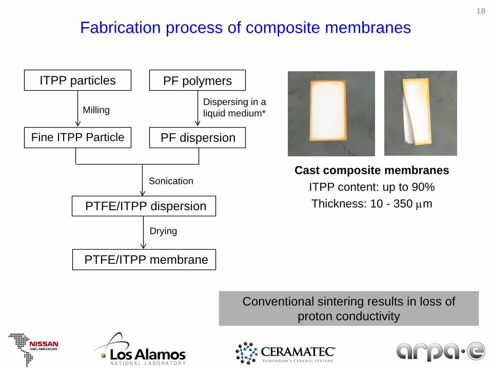
PF polymers
Fabrication process of composite membranes
Dispersing in a liquid medium*
PF dispersion
Sonication
PTFE/ITPP dispersion
Drying
PTFE/ITPP membrane
Cast composite membranesITPP content: up to 90%Thickness: 10 - 350 µm
ITPP particles
Milling
Fine ITPP Particle
18
Conventional sintering results in loss of proton conductivity
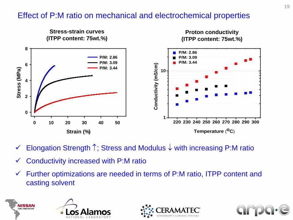
Effect of P:M ratio on mechanical and electrochemical properties
Strain (%)
0 10 20 30 40 50
Stre
ss (M
Pa)
0
2
4
6
8
P/M: 2.86P/M: 3.09P/M: 3.44
Stress-strain curves(ITPP content: 75wt.%)
220 230 240 250 260 270 280 290 3001
10
P/M: 2.86 P/M: 3.09 P/M: 3.44
Cond
uctiv
ity (m
S/cm
)
Temperature (oC)
Proton conductivity(ITPP content: 75wt.%)
Elongation Strength ↑; Stress and Modulus ↓ with increasing P:M ratio
Conductivity increased with P:M ratio
Further optimizations are needed in terms of P:M ratio, ITPP content and casting solvent
19
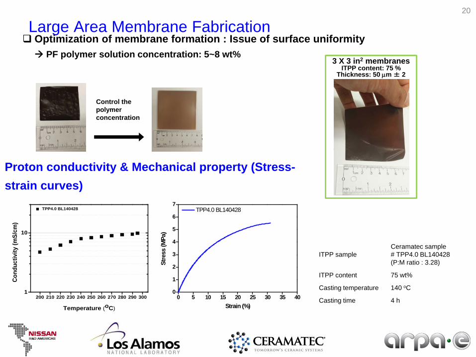
200 210 220 230 240 250 260 270 280 290 3001
10
TPP4.0 BL140428
Cond
uctiv
ity (m
S/cm
)
Temperature (oC)
Large Area Membrane Fabrication Optimization of membrane formation : Issue of surface uniformity PF polymer solution concentration: 5~8 wt%
Control the polymer concentration
3 X 3 in2 membranes ITPP content: 75 %
Thickness: 50 µm ± 2
0 5 10 15 20 25 30 35 400
1
2
3
4
5
6
7
Stre
ss (M
Pa)
Strain (%)
TPP4.0 BL140428
Membrane preparation information
ITPP sampleCeramatec sample# TPP4.0 BL140428(P:M ratio : 3.28)
ITPP content 75 wt%
Casting temperature 140 oC
Casting time 4 h
Proton conductivity & Mechanical property (Stress-strain curves)
20
Performance_TPP90wt%/PA21
Best performance in H2/O2 condition with 30psi back pressure
ConditionMembrane thickness: 120 µmAnode/Cathode/Cell Temp: 80/80/220 oCH2/Air (H2/O2): 200/200 sccmBack pressure: varied (0-30 psi)Pt loading: 3.5 mg/cm2
Sample HFR(Ω cm2)
Conductivity(mS/cm)
H2/Airno back pressure
0.37 ~ 0.4 30 ~ 33
H2/Air 30 psi 0.40 ~ 0.44 27 ~ 30
H2/O2 30 psi 0.30 ~ 0.34 35 ~ 40
0.0 0.2 0.4 0.6 0.8 1.0 1.2 1.4 1.60.0
0.1
0.2
0.3
0.4
0.5
0.6
0.7
0.8
0.9
1.0
Cell
pote
ntia
l (V)
Current density (A/cm2)
H2/Air no back pressure H2/Air 30 psi H2/O2 30 psi
0
50
100
150
200
250
300
350
400
450
Pow
er d
ensi
ty (m
W/c
m2 )
0.0 0.5 1.0 1.5
0.3
0.4
0.5
HFR
(Ω c
m2 )
Current density (A/cm2)
TPP90wt%/PA (electrode: Pt Black + TPP)
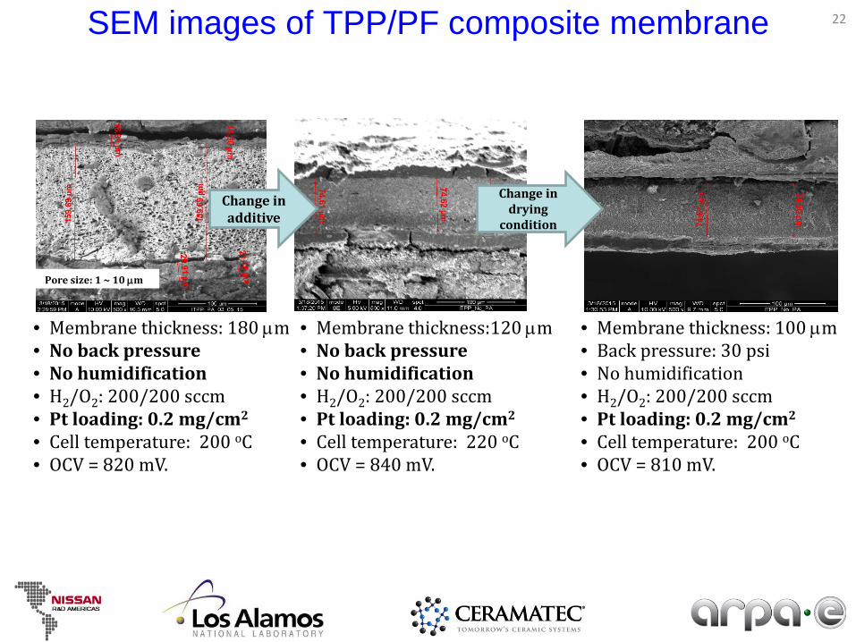
SEM images of TPP/PF composite membrane
• Membrane thickness: 100 µm• Back pressure: 30 psi• No humidification• H2/O2: 200/200 sccm• Pt loading: 0.2 mg/cm2
• Cell temperature: 200 oC• OCV = 810 mV.
• Membrane thickness: 180 µm• No back pressure• No humidification• H2/O2: 200/200 sccm• Pt loading: 0.2 mg/cm2
• Cell temperature: 200 oC• OCV = 820 mV.
• Membrane thickness:120 µm• No back pressure• No humidification• H2/O2: 200/200 sccm• Pt loading: 0.2 mg/cm2
• Cell temperature: 220 oC• OCV = 840 mV.
Pore size: 1 ~ 10 µm
Change in additive
Change in drying
condition
22
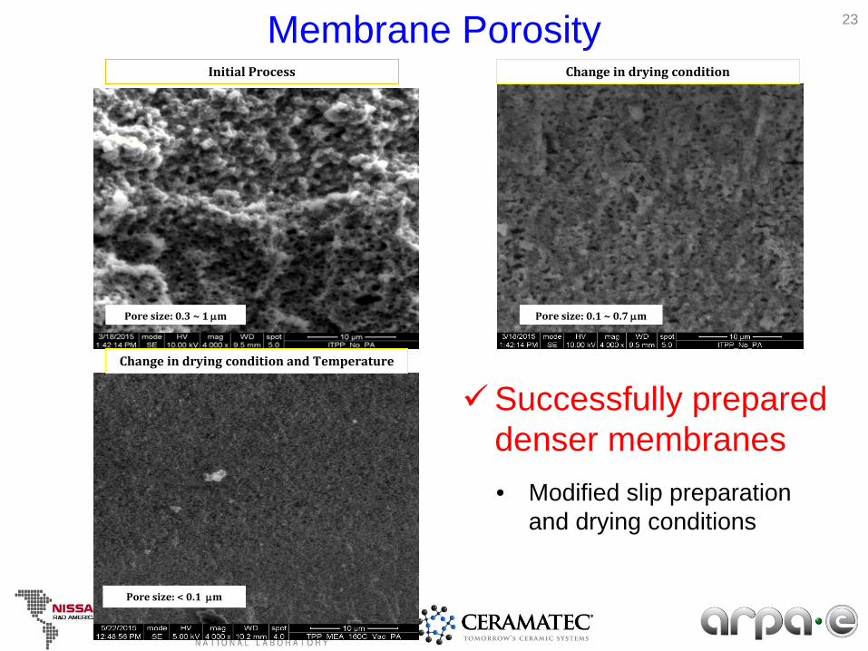
Membrane Porosity 23
Pore size: 0.3 ~ 1 µm Pore size: 0.1 ~ 0.7 µm
Pore size: < 0.1 µm
Initial Process Change in drying condition
Change in drying condition and Temperature
• Modified slip preparation and drying conditions
Successfully prepared denser membranes
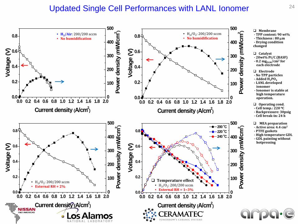
Updated Single Cell Performances with LANL Ionomer
0.0 0.2 0.4 0.6 0.8 1.0 1.2 1.4 1.6 1.8 2.00.0
0.2
0.4
0.6
0.8 200 oC 220 oC 240 oC
Current density (A/cm2)
0
100
200
300
400
500Vo
ltage
(V)
Pow
er d
ensi
ty (m
W/c
m2 )
Temperature effect• H2/O2: 200/200 sccm• External RH = 1~3%
0.0 0.2 0.4 0.6 0.8 1.0 1.2 1.4 1.6 1.8 2.00.0
0.2
0.4
0.6
0.8
Current density (A/cm2)
0
100
200
300
400
500
Volta
ge (V
)
Pow
er d
ensi
ty (m
W/c
m2 )
0.0 0.2 0.4 0.6 0.8 1.0 1.2 1.4 1.6 1.8 2.00.0
0.2
0.4
0.6
0.8
Current density (A/cm2)
0
100
200
300
400
500
Volta
ge (V
)
Pow
er d
ensi
ty ( m
W/c
m2 )
0.0 0.2 0.4 0.6 0.8 1.0 1.2 1.4 1.6 1.8 2.00.0
0.2
0.4
0.6
0.8
Current density (A/cm2)
0
100
200
300
400
500
Volta
ge (V
)
Pow
er d
ensi
ty (m
W/c
m2 )
• H2/Air: 200/200 sccm• No humidification
• H2/O2: 200/200 sccm• No humidification
• H2/O2: 200/200 sccm• External RH = 2%
24
Membrane- TPP content: 90 wt%- Thickness : 80 µm- Drying condition changed
Catalyst - 20wt% Pt/C (BASF)- 0.2 mgPGM/cm2 for
each electrode
Electrode - No TPP particles- Added H3PO4- LANL developed
ionomer- Ionomer is stable at
high temperature operation.
Operating cond.- Cell temp.: 220 oC- Backpressure: 30psig- Cell break-in: 24 h
MEA preparation- Active area: 4.4 cm2
- PTFE gaskets- High temperature GDL- GDL painting without
hotpressing
Current density (A/cm2)
0.0 0.5 1.0 1.5 2.0
Cel
l vol
tage
(V)
0.0
0.1
0.2
0.3
0.4
0.5
0.6
0.7
0.8
0.9
1: 08/26/142: 03/05/153: 06/01/15
Current density (A/cm2)
0.0 0.5 1.0 1.5 2.0
Pow
er d
ensi
ty (m
W/c
m2 )
0
100
200
300
400
500
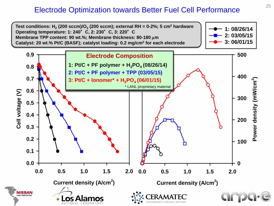
Electrode Optimization towards Better Fuel Cell Performance
Test conditions: H2 (200 sccm)/O2 (200 sccm); external RH = 0-2%; 5 cm2 hardwareOperating temperature: 1: 240°C, 2: 230°C, 3: 220°CMembrane TPP content: 90 wt.%; Membrane thickness: 80-180 µmCatalyst: 20 wt.% Pt/C (BASF); catalyst loading: 0.2 mg/cm2 for each electrode
Electrode Composition1: Pt/C + PF polymer + H3PO4 (08/26/14)2: Pt/C + PF polymer + TPP (03/05/15)3: Pt/C + Ionomer* + H3PO4 (06/01/15)
* LANL proprietary material
25
Conclusions• Reproducible, high conductivity in scaled up
powder batches– Proton Conductivity of 0.1 S/cm
• High loading of TPP in polymer composite• Single 5 cm2 membrane performance of ~ 300
mW/cm2 demonstrated (High Pt loading) –porous membrane
• Dense composite membrane fabricated• Low Pt loading (0.2 mg/cm2), ionomer in GDE,
5 cm2 cell demonstrated >400 mW/cm2
• Early versions of cells demonstrated in 50 cm2
size
26
Remaining Challenges
• Increase in OCV• High performance cells in 25 cm2 and 50
cm2 size• Design/build/test multi-cell stack• Long term performance stability evaluation• CO tolerance evaluation• Complete cost model
27
Acknowledgement
• ARPA-E Team– Program Director: Dr. John Lemmon– Technical Support: Dr. Scott Litzelman– Tech to Market: Mr. Sven Mumme
28
Recommended