SAIVER – Pantone: 2925C 219mmx64mm
Integrated VarIable refrIgerant flow aHU/PaU(r410a)
CONTENTS
Features of VRF AHU/PAU 2
WELAIRE i-GT Concept 9
VRF Outdoor Unit Performance Data 10
Drawings & Performance Data 12
Dimensions 13
Notes 14
Features of VRF AHU/PAU
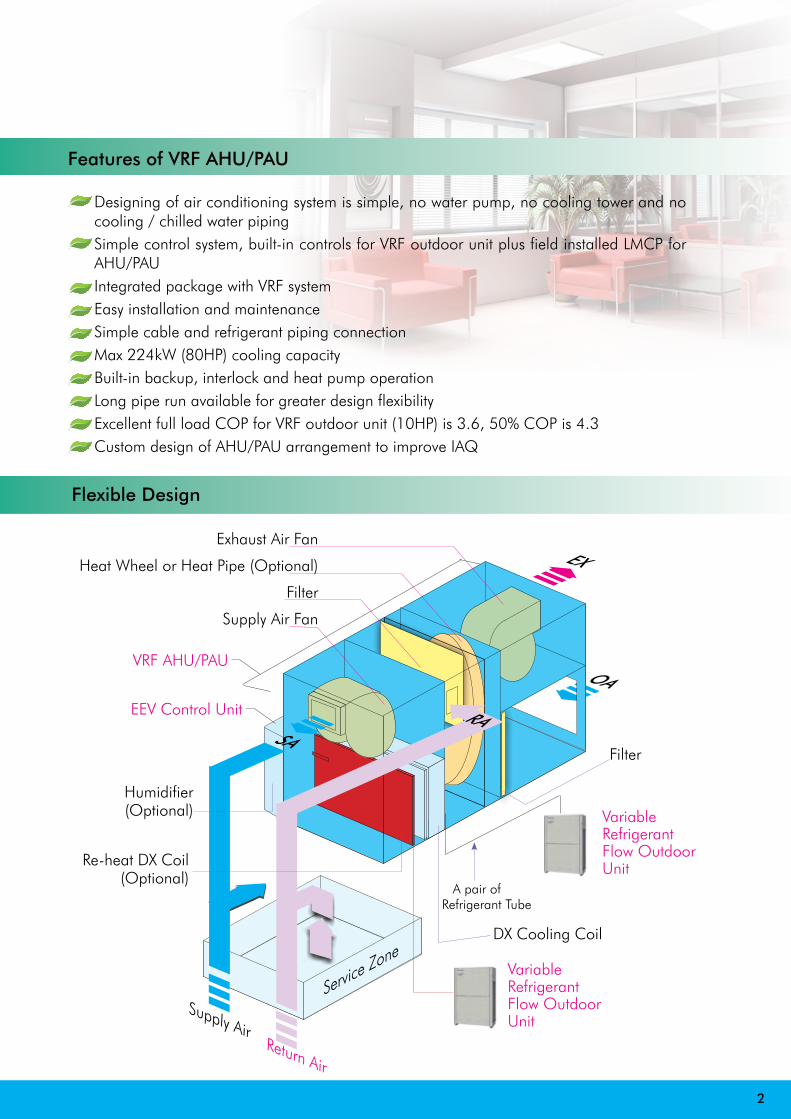
Designing of air conditioning system is simple, no water pump, no cooling tower and no cooling / chilled water pipingSimple control system, built-in controls for VRF outdoor unit plus field installed LMCP for AHU/PAUIntegrated package with VRF systemEasy installation and maintenanceSimple cable and refrigerant piping connectionMax 224kW (80HP) cooling capacityBuilt-in backup, interlock and heat pump operationLong pipe run available for greater design flexibilityExcellent full load COP for VRF outdoor unit (10HP) is 3.6, 50% COP is 4.3Custom design of AHU/PAU arrangement to improve IAQ
2
Exhaust Air Fan
Heat Wheel or Heat Pipe (Optional)
Filter
Supply Air Fan
VRF AHU/PAU
Filter
Variable Refrigerant Flow Outdoor Unit
DX Cooling Coil
Humidifier (Optional)
SA
EX
OA
RA
Service Zone
A pair ofRefrigerant Tube
Supply AirReturn Air
Flexible Design
EEV Control Unit
Variable Refrigerant Flow Outdoor Unit
Re-heat DX Coil(Optional)
3
Chiller systemMachine Room
PAUChillerPump Water
TankPAU
VRF AHU/PAU system
VRFAHU/PAU
√
√
√
√
√
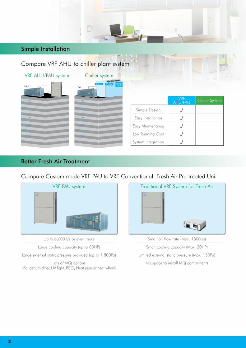
Simple Design
Easy Installation
Easy Maintenance
Low Running Cost
System Integration
Chiller System
Simple Installation
Compare VRF AHU to chiller plant system
Up to 6,000 l/s or even more
Large cooling capacity (up to 80HP)
Large external static pressure provided (up to 1,800Pa)
Lots of IAQ options (Eg. dehumidifier, UV light, PCO, Heat pipe or heat wheel)
VRF PAU system
Small air flow rate (Max. 1800l/s)
Small cooling capacity (Max. 20HP)
Limited external static pressure (Max. 150Pa)
No space to install IAQ components
Traditional VRF System for Fresh Air
Better Fresh Air Treatment
Compare Custom made VRF PAU to VRF Conventional Fresh Air Pre-treated Unit
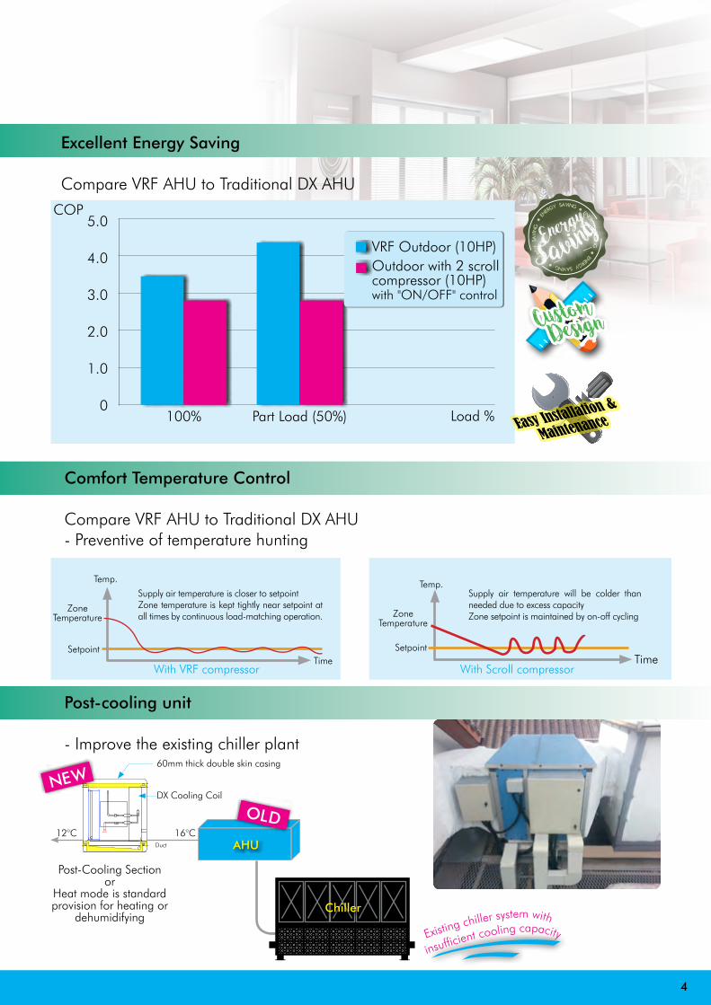
Comfort Temperature Control
Compare VRF AHU to Traditional DX AHU- Preventive of temperature hunting
Time
Temp.
With Scroll compressor
Supply air temperature will be colder than needed due to excess capacityZone setpoint is maintained by on-off cycling Zone
Temperature
SetpointTime
Temp.
With VRF compressor
Supply air temperature is closer to setpointZone temperature is kept tightly near setpoint at all times by continuous load-matching operation.
ZoneTemperature
Setpoint
Post-cooling unit
- Improve the existing chiller plant
JJ JJ JJ JJ JJJJ JJ JJ JJ JJ
Chiller
AHU
Post-Cooling Sectionor
Heat mode is standard provision for heating or
dehumidifying
16°C12°CDuct
rinsufficient cooling capacityExistin
g chiller system with
4
OLD
NEWDX Cooling Coil
60mm thick double skin casing
Excellent Energy Saving
Compare VRF AHU to Traditional DX AHU
COP5.0
4.0
3.0
2.0
1.0
0Part Load (50%)100%
VRF Outdoor (10HP)Outdoor with 2 scroll compressor (10HP) with "ON/OFF" control
Energy● ENERGY
SAVIN
G ● ENERGY SAVING ● E
NERG
Y SA
VIN
G ●
ENERG
Y SAVING
Savin
g
Custom Design
Easy Installation &
MaintenanceLoad %

Individual control is possible for Max. 32 AHUs. Control of 32 AHUs / PAUs individually into 4 zones. (One zone can have up to 8 units) Control is possible for ON/OFF, operation mode, operation monitoring, alarm monitoring, remote controller local operation prohibition, etc…
- Duty and Standby functionIf the duty AHU have fault, the standby AHU will be cut-in automatically in 30 seconds
Control System
Compare VRF AHU to Traditional DX system- Interlock function
When AHU started operation, it activates PAU to run automatically with simple wiring connection
PAU "ON"AHU "ON"
Automatic Mode
Unit "ON"(Standby unit)
Alarm occured(Duty Unit)
Duty & Standby Mode
AHU/PAU Timer wired remote controller
System Controller
Serial Interface for LonWorks Network
-Function ON/OFF- Mode setting- Temperature setting (AHU only)- Weekly program- Alarm history
NEW
This interfaces is a communication converter for connecting LonWorks to the control network.From the host connected to LonWorks, basic settings of status monitoring is possible for up to 32 no. of AHU/PAU.LonWorks
Interface Board
5
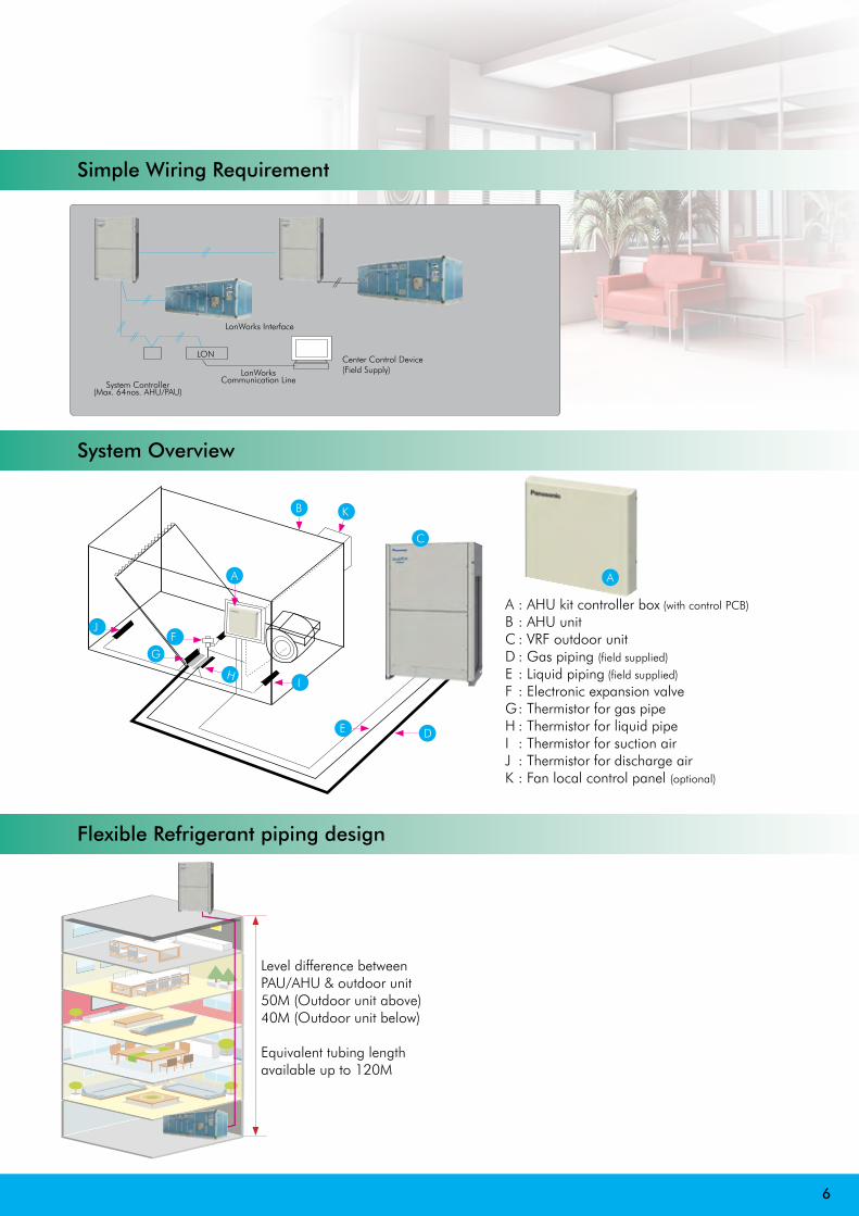
Simple Wiring Requirement
LonWorks Interface
LONCenter Control Device(Field Supply)LonWorks
Communication LineSystem Controller(Max. 64nos. AHU/PAU)
System Overview
To find out how Panasonic cares for you, log on to: www.aircon.panasonic.eu Contact Details: Telephone: 01344 853182 / www.aircon.panasonic.euAddress: Panasonic Air Conditioning: Panasonic House // Willoughby Road // Bracknell // Berkshire // RG12 8FP
www.eggeassocia
ts.net
AHU CONNECTION KIT, 28 kW AND 56 kW FOR ECOi AND ECO G
Cooling capacity
Heating capacity
Horsepower Cooling Airflow Bypass Factor Dimensions of the box
Piping length Elevation diff. (in/out)
Pipe Diameters Intake temperature of AHU Kit
Ambient temperature of outdoor unit
Nominal Nominal High / Low H x W x D Min / Max Max Liquid pipe Gas pipe Min / Max Min / Max
kW kW HP m³/min mm m m Inch (mm) Inch (mm) °C °C
CZ-280MAH1 28.0 31.5 10 5,000 / 3,500 0.9 (recommended) 420 x 280 x 160 10 / 100 10 3/8 (9.52) 7/8 (22.22) Cooling:18 - 32DB(13 - 23 WB) / Heating:16 - 30 DB
Cooling: -5 - 43 DB / Heating: -15 - 15.5 WB
CZ-560MAH1 56.0 63.0 20 10,000 / 7,000 0.9 (recommended) 420 x 280 x 160 10 / 100 10 5/8 (15.88) 1 1/8 (28.58)
CZ-280MAH1 + CZ-560MAH1 84.0 95.0 30 15,000 / 10,500 0.9 (recommended) 420 x 280 x 160 10 / 100 10 3/4 (19.05) 1 1/4 (31.75)
CZ-560MAH1 x2 112.0 127.0 40 20,000 / 14,000 0.9 (recommended) 420 x 280 x 160 10 / 100 10 3/4 (19.05) 1 1/2 (38.15)
CZ-560MAH1 x2 + CZ-280MAH1 140.0 155.0 50 25,000 / 17,500 0.9 (recommended) 420 x 280 x 160 10 / 100 10 3/4 (19.05) 1 1/2 (38.15)
CZ-560MAH1 x3 168.0 189.0 60 30,000 / 21,000 0.9 (recommended) 420 x 280 x 160 10 / 100 10 3/4 (19.05) 1 1/2 (38.15)
Due t
o the
ongo
ing in
nova
tion o
f our
prod
ucts
, the
spec
ifi ca
tions
of th
is ca
talog
ue ar
e vali
d bar
ring t
ypog
raph
ic er
rors
, and
may
be su
bject
to m
inor m
odifi
catio
ns by
the m
anuf
actu
rer w
ithou
t prio
r war
ning i
n ord
er to
impr
ove t
he pr
oduc
t. Th
e tot
al or
parti
al re
prod
uctio
n of t
his ca
talog
ue is
proh
ibite
d with
out t
he ex
pres
s aut
horis
ation
of P
anas
onic
UK Lt
d.
AIR HANDLING UNIT KIT TO CONNECT TO YOUR VENTILATION SYSTEM5-25 kW FOR PACi28 kW AND 56 kW FOR ECOi AND GHP
AHU CONNECTION KITPCB, Power trans, Terminal block
OPTIONAL REMOTE CONTROLLERStandard wired remote controller. CZ-RTC2
Remote control can be easily installed on the AHU Kit box. Remote control must be purchase separately.
Expansion valve
Thermistor x2(Refrigerant: E1, E3)
Thermistor x2 (x1 in PACi)(Air: Tf, Tb)
Optional parts: Following functions are available by using different type of control accessories:
CZ-RTC2 Wired remote controller· Operation-ON/OFF· Mode select· Temperature setting* Fan operation signal can be taken from the PCB.
CZ-T10 terminal · Input signal= Operation ON/OFF· Remote controller prohibition· Output signal= Operating-ON status· Alarm output (by DC12 V)PAW-OCT, DC12 V outlet. Option terminal· Output signal= Cool / Heat/Fan status· Defrost· Thermostat-ON
CZ-CAPBC2 Mini seri-para I/O unit · Temperature setting by 0-10 V or 0-140 Ω input signal· Room (inlet air) temp outlet by 4-20 mA· Mode select or/and ON/OFF control· Fan operation control· Operation status output/ Alarm output
AHU Connection Kit / System CombinationCapacity (HP) Outdoor unit combination
AHU kit combination
PACiAll capacities Common use for all outdoor units Standard and Elite CZ-280PAH1 (Only 1 by 1 connection is allowed)
2-PIPE ECOi 6N SERIES 28 kW (10 HP) U-10ME1E81CZ-280MAH1
56 kW (20 HP) U-20ME1E81CZ-560MAH1
84 kW (30 HP) U-16ME1E81 U-14ME1E81CZ-560MAH1 CZ-280MAH1
112 kW (40 HP) U-20ME1E81 U-20ME1E81CZ-560MAH1 CZ-560MAH1
140 kW (50 HP) U-18ME1E81 U-16ME1E81 U-16ME1E81 CZ-560MAH1 CZ-560MAH1 CZ-280MAH1
168 kW (60 HP) U-20ME1E81 U-20ME1E81 U-20ME1E81 CZ-560MAH1 CZ-560MAH1 CZ-560MAH1
ECO G AND ECO G MULTI 56 kW (20 HP) U-20GE2E5CZ-560MAH1
Technical Zoom· Maximum capacity: 60 HP (168 kW)· Maximum piping length: 180 m· Maximum total piping: 210 m· Elevation difference (in/out):
50 m (outdoor unit above)· Elevation difference (in/in): 4 m· In/Out capacity ratio: 50~100%.
Maximum indoor units number: 2 units· Available temperature range in Heating: -15~15.5 °C· Available temperature range for the suction air at AHU Kit: Cool: 15~24 °C / Heat: 10~30 °CCZ-280PAH1 // CZ-280MAH1 // CZ-560MAH1· The system controlled by the suction air (or return air from room) temperature as same as standard indoor unit. (Selectable mode: Automatic / Cooling / Heating / Fan / Dry (but same as Cool)· The discharge air temperature is also controlled to prevent too-low air discharge in Cooling or too-high air discharge in Heating. (in case of VRF system)· Demand control (Forcible thermostat-OFF control by operating current)· Defrost operation signal, Thermo-ON/OFF states output· Drain pump control (Drain-pump and the float switch to be supplied in local)· External target temperature setting via Indoor/Outdoor signal interface is available with CZ-CAPBC2. (Ex. 0 – 10 V)· Connectable with P-LINK system· Fan control signal from the PCB can be used for control the air volume (High/Mid/Low and LL for Th-off)
SYSTEM & REGULATIONS. SYSTEM OVERVIEWA: AHU Kit controller box (with control PCB)B: AHU Kit equipment (Field supplied)C: AHU Kit system controller (Field supplied)D: Outdoor unitF: Gas piping (Field supplied)
G: Liquid piping (Field supplied)H: Electronic expansion valveI: Thermistor for Gas pipeJ: Thermistor for Liquid pipeK: Thermister for Suction airL: Thermistor for Discharge air
A
C
EB
L
H JI
KF
GD
A
C
EB
L
H JI
KF
GD
Calculation software is available onwww.panasonicproclub.comOr connect simply with your Smartphone to the PRO Club using this QR.
PRO Club
A
KB
FG
J
DE
IH
A : AHU kit controller box (with control PCB)
B : AHU unit C : VRF outdoor unitD : Gas piping (field supplied)
E : Liquid piping (field supplied)
F : Electronic expansion valveG : Thermistor for gas pipeH : Thermistor for liquid pipeI : Thermistor for suction airJ : Thermistor for discharge airK : Fan local control panel (optional)
C
Flexible Refrigerant piping design
A
6
Level difference between PAU/AHU & outdoor unit50M (Outdoor unit above)40M (Outdoor unit below)
Equivalent tubing length available up to 120M
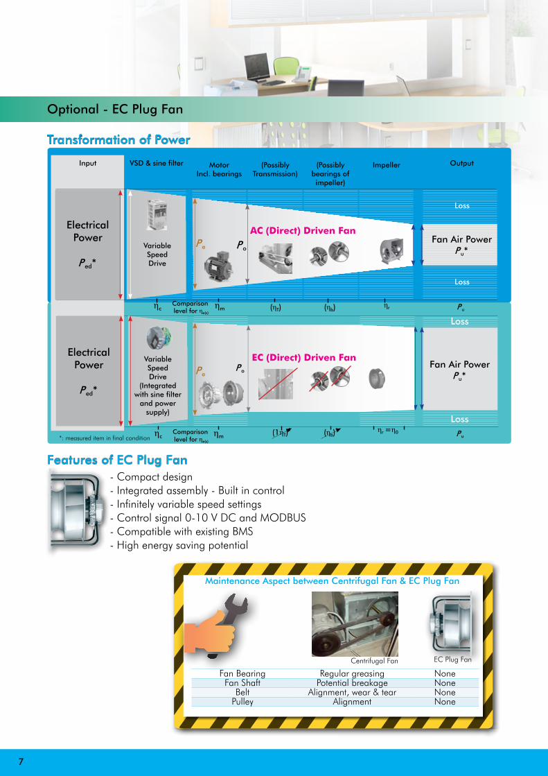
Optional - EC Plug Fan
Po
Comparison level for ηe(s)
7
Transformation of Power
Features of EC Plug Fan - Compact design - Integrated assembly - Built in control - Infinitely variable speed settings - Control signal 0-10 V DC and MODBUS - Compatible with existing BMS - High energy saving potential
Maintenance Aspect between Centrifugal Fan & EC Plug Fan
Fan Bearing Regular greasing NoneFan Shaft Potential breakage None
Belt Alignment, wear & tear NonePulley Alignment None
EC Plug FanCentrifugal Fan
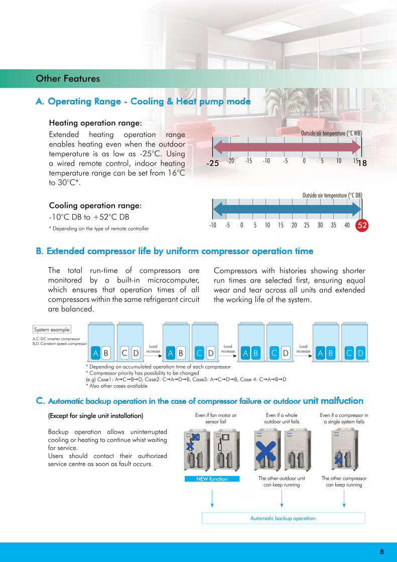
A. Operating Range - Cooling & Heat pump mode
B. Extended compressor life by uniform compressor operation time
C. Automatic backup operation in the case of compressor failure or outdoor unit malfuction
Other Features
Heating operation range:Extended heating operation range enables heating even when the outdoor temperature is as low as -25°C. Using a wired remote control, indoor heating temperature range can be set from 16°C to 30°C*.
Cooling operation range:-10°C DB to +52°C DB* Depending on the type of remote controller
The total run-time of compressors are monitored by a built-in microcomputer, which ensures that operation times of all compressors within the same refrigerant circuit are balanced.
Compressors with histories showing shorter run times are selected first, ensuring equal wear and tear across all units and extended the working life of the system.
A B C D A B C D A B C D A B C D
System example
A,C : DC inverter compressorB,D : Constant speed compressor
Loadincrease
Loadincrease
Loadincrease
* Depending on accumulated operation time of each compressor* Compressor priority has possibility to be changed(e.g) Case1: AACABAD, Case2: CAAADAB, Case3: AACADAB, Case 4: CAAABAD* Also other cases available
(Except for single unit installation)
Backup operation allows uninterrupted cooling or heating to continue whist waiting for service.Users should contact their authorized service centre as soon as fault occurs.
The other compressor can keep running
Even if a compressor in a single system fails
The other outdoor unit can keep running
Even if a whole outdoor unit fails
Even if fan motor or sensor fail
NEW function
Automatic backup operation.
8
XX
XX
Outside air temperature (°C WB)
Outside air temperature (°C DB)
-25 -20 -15 -10 -5 0 5 10 1518
-10 -5 0 5 10 15 20 25 30 35 40 52

VRF Dual Coil (CHW+DX) Package Air Handling Unit
9
Slim Type VRF Dual Coil (CHW+DX) Package Air Handling Unit (Slim VDC AHU)
Slim VDC AHUFY
Filter section(Optional)
EC Plug Fan (Multi-fans for standby/duty
function)
DX Coil C/W variable flow
electrical expansion valve
Water Coil C/W 2-way
valve
Length in mm = 1450(+250)Width in mm = 900
Height in mm=650
Internal lining
EC plug fan
DX cooling coil
Chilled water coil
Features of Dual coil design- Back-up function- Post cooling function- Dehumidity function- Light-load function
- mini shop- Server room
CONCEPTInnovatIve Green & technoloGy SolutIon
10
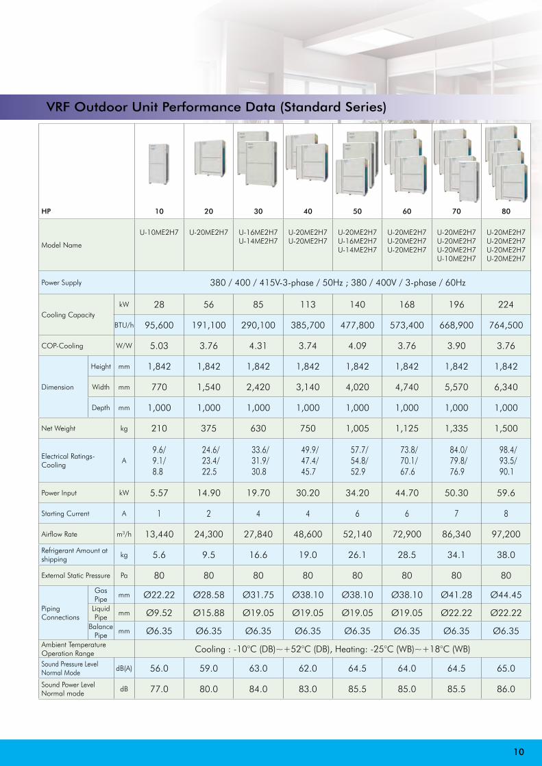
VRF Outdoor Unit Performance Data (Standard Series)
HP 10 20 30 40 50 60 70 80
Model Name
U-10ME2H7 U-20ME2H7 U-16ME2H7U-14ME2H7
U-20ME2H7U-20ME2H7
U-20ME2H7U-16ME2H7U-14ME2H7
U-20ME2H7U-20ME2H7U-20ME2H7
U-20ME2H7U-20ME2H7U-20ME2H7U-10ME2H7
U-20ME2H7U-20ME2H7U-20ME2H7U-20ME2H7
Power Supply 380 / 400 / 415V-3-phase / 50Hz ; 380 / 400V / 3-phase / 60Hz
Cooling CapacitykW 28 56 85 113 140 168 196 224
BTU/h 95,600 191,100 290,100 385,700 477,800 573,400 668,900 764,500
COP-Cooling W/W 5.03 3.76 4.31 3.74 4.09 3.76 3.90 3.76
Dimension
Height mm 1,842 1,842 1,842 1,842 1,842 1,842 1,842 1,842
Width mm 770 1,540 2,420 3,140 4,020 4,740 5,570 6,340
Depth mm 1,000 1,000 1,000 1,000 1,000 1,000 1,000 1,000
Net Weight kg 210 375 630 750 1,005 1,125 1,335 1,500
Electrical Ratings-Cooling
A9.6/9.1/8.8
24.6/23.4/22.5
33.6/31.9/30.8
49.9/47.4/45.7
57.7/54.8/52.9
73.8/70.1/67.6
84.0/79.8/76.9
98.4/93.5/90.1
Power Input kW 5.57 14.90 19.70 30.20 34.20 44.70 50.30 59.6
Starting Current A 1 2 4 4 6 6 7 8
Airflow Rate m3/h 13,440 24,300 27,840 48,600 52,140 72,900 86,340 97,200
Refrigerant Amount at shipping
kg 5.6 9.5 16.6 19.0 26.1 28.5 34.1 38.0
External Static Pressure Pa 80 80 80 80 80 80 80 80
Piping Connections
Gas Pipe
mm Ø22.22 Ø28.58 Ø31.75 Ø38.10 Ø38.10 Ø38.10 Ø41.28 Ø44.45Liquid Pipe
mm Ø9.52 Ø15.88 Ø19.05 Ø19.05 Ø19.05 Ø19.05 Ø22.22 Ø22.22Balance
Pipemm Ø6.35 Ø6.35 Ø6.35 Ø6.35 Ø6.35 Ø6.35 Ø6.35 Ø6.35
Ambient Temperature Operation Range Cooling : -10°C (DB)~+52°C (DB), Heating: -25°C (WB)~+18°C (WB)
Sound Pressure Level Normal Mode
dB(A) 56.0 59.0 63.0 62.0 64.5 64.0 64.5 65.0
Sound Power Level Normal mode
dB 77.0 80.0 84.0 83.0 85.5 85.0 85.5 86.0
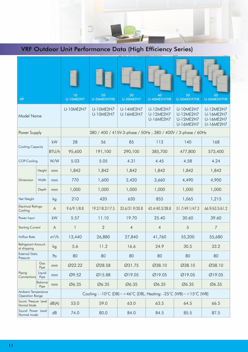
VRF Outdoor Unit Performance Data (High Efficiency Series)
HP10
U-10ME2H720
U-20ME2H7HE30
U-30ME2H740
U-40ME2H7HE50
U-50ME2H7HE60
U-60ME2H7HE
Model Name
U-10ME2H7 U-10ME2H7 U-10ME2H7
U-14ME2H7U-16ME2H7
U-12ME2H7U-12ME2H7U-16ME2H7
U-10ME2H7U-12ME2H7U-12ME2H7U-16ME2H7
U-12ME2H7U-16ME2H7U-16ME2H7U-16ME2H7
Power Supply 380 / 400 / 415V-3-phase / 50Hz ; 380 / 400V / 3-phase / 60Hz
Cooling CapacitykW 28 56 85 113 140 168
BTU/h 95,600 191,100 290,100 385,700 477,800 573,400
COP-Cooling W/W 5.03 5.05 4.31 4.45 4.58 4.24
Dimension
Height mm 1,842 1,842 1,842 1,842 1,842 1,842
Width mm 770 1,600 2,420 3,660 4,490 4,900
Depth mm 1,000 1,000 1,000 1,000 1,000 1,000
Net Weight kg 210 420 630 855 1,065 1,215
Electrical Ratings-Cooling A 9.6/9.1/8.8 19.2/18.2/17.5 33.6/31.9/30.8 42.4/40.3/38.8 51.7/49.1/47.3 66.9/63.5/61.2
Power Input kW 5.57 11.10 19.70 25.40 30.60 39.60
Starting Current A 1 2 4 4 5 7
Airflow Rate m3/h 13,440 26,880 27,840 41,760 55,200 55,680
Refrigerant Amount at shipping kg 5.6 11.2 16.6 24.9 30.5 33.2
External Static Pressure Pa 80 80 80 80 80 80
PipingConnections
Gas Pipe mm Ø22.22 Ø28.58 Ø31.75 Ø38.10 Ø38.10 Ø38.10
Liquid Pipe mm Ø9.52 Ø15.88 Ø19.05 Ø19.05 Ø19.05 Ø19.05
Balance Pipe mm Ø6.35 Ø6.35 Ø6.35 Ø6.35 Ø6.35 Ø6.35
Ambient Temperature Operation Range Cooling : -10°C (DB)~+46°C (DB), Heating: -25°C (WB)~+15°C (WB)
Sound Pressure Level Normal Mode dB(A) 53.0 59.0 63.0 63.5 64.5 66.5
Sound Power Level Normal mode dB 74.0 80.0 84.0 84.5 85.5 87.5
11
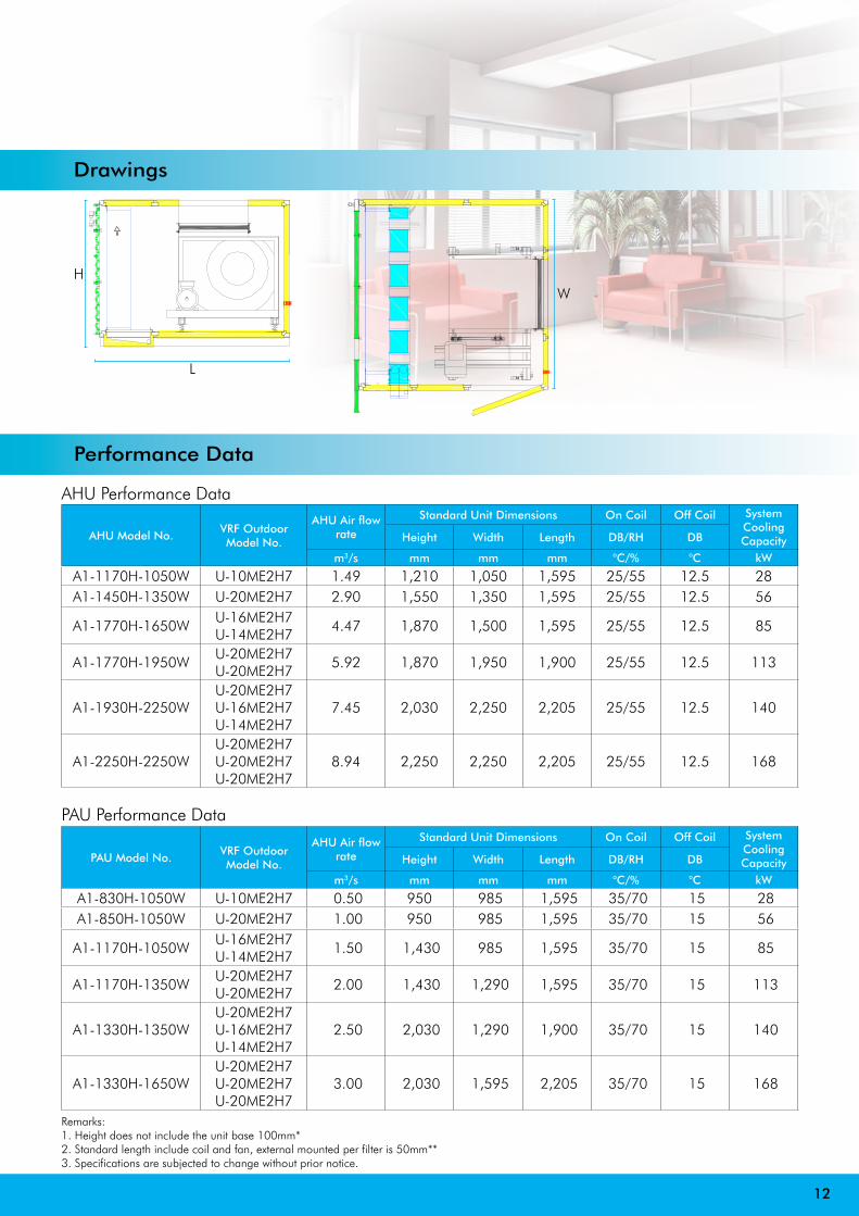
Drawings
Performance Data
AHU Model No.VRF Outdoor Model No.
AHU Air flow rate
Standard Unit Dimensions On Coil Off Coil SystemCooling CapacityHeight Width Length DB/RH DB
m3/s mm mm mm °C/% °C kW
A1-1170H-1050W U-10ME2H7 1.49 1,210 1,050 1,595 25/55 12.5 28A1-1450H-1350W U-20ME2H7 2.90 1,550 1,350 1,595 25/55 12.5 56
A1-1770H-1650WU-16ME2H7U-14ME2H7
4.47 1,870 1,500 1,595 25/55 12.5 85
A1-1770H-1950WU-20ME2H7U-20ME2H7
5.92 1,870 1,950 1,900 25/55 12.5 113
A1-1930H-2250WU-20ME2H7U-16ME2H7U-14ME2H7
7.45 2,030 2,250 2,205 25/55 12.5 140
A1-2250H-2250WU-20ME2H7U-20ME2H7U-20ME2H7
8.94 2,250 2,250 2,205 25/55 12.5 168
AHU Performance Data
PAU Model No.VRF Outdoor Model No.
AHU Air flow rate
Standard Unit Dimensions On Coil Off Coil SystemCooling CapacityHeight Width Length DB/RH DB
m3/s mm mm mm °C/% °C kW
A1-830H-1050W U-10ME2H7 0.50 950 985 1,595 35/70 15 28 A1-850H-1050W U-20ME2H7 1.00 950 985 1,595 35/70 15 56
A1-1170H-1050WU-16ME2H7U-14ME2H7
1.50 1,430 985 1,595 35/70 15 85
A1-1170H-1350WU-20ME2H7U-20ME2H7
2.00 1,430 1,290 1,595 35/70 15 113
A1-1330H-1350WU-20ME2H7U-16ME2H7U-14ME2H7
2.50 2,030 1,290 1,900 35/70 15 140
A1-1330H-1650WU-20ME2H7U-20ME2H7U-20ME2H7
3.00 2,030 1,595 2,205 35/70 15 168
PAU Performance Data
Remarks:1. Height does not include the unit base 100mm*2. Standard length include coil and fan, external mounted per filter is 50mm**3. Specifications are subjected to change without prior notice.
12
WH
L
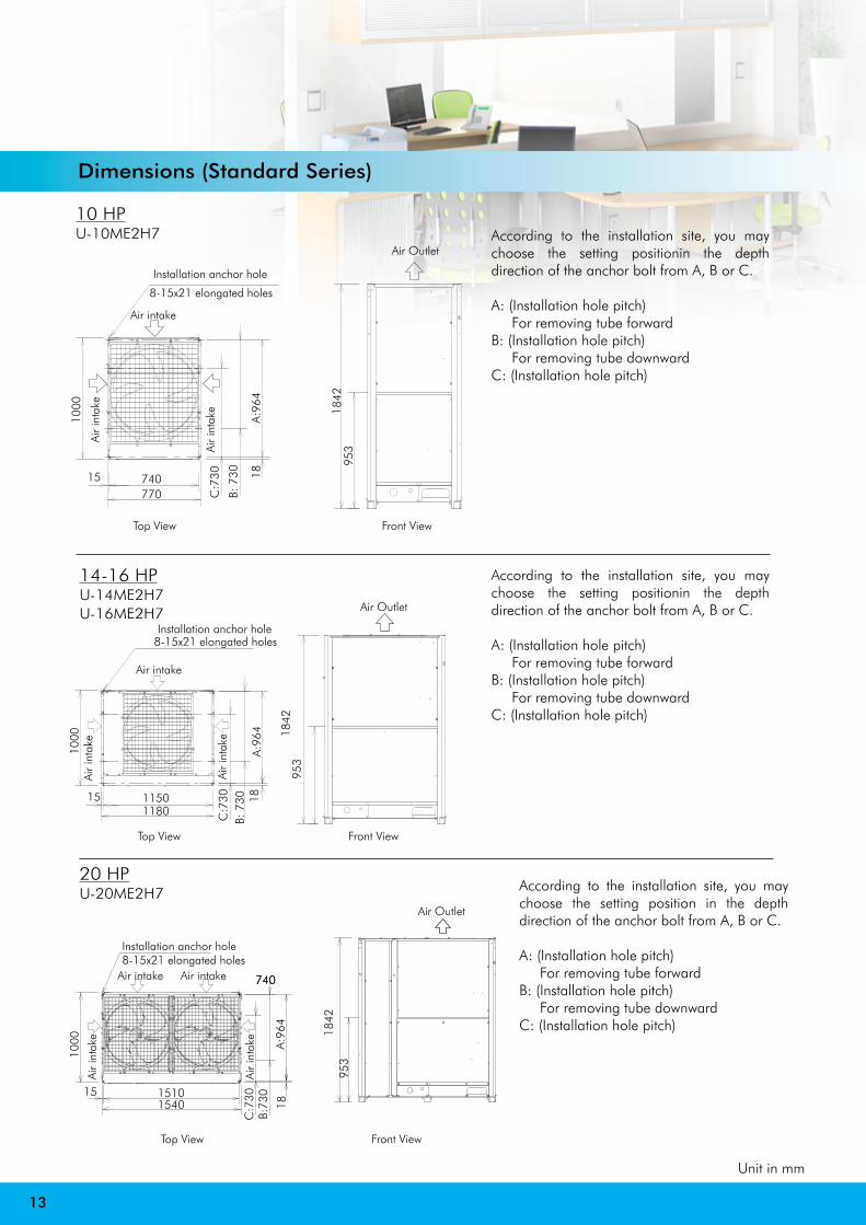
Dimensions (Standard Series)
According to the installation site, you may choose the setting positionin the depth direction of the anchor bolt from A, B or C.
A: (Installation hole pitch) For removing tube forward
B: (Installation hole pitch) For removing tube downward
C: (Installation hole pitch)
10 HPU-10ME2H7
14-16 HPU-14ME2H7U-16ME2H7
According to the installation site, you may choose the setting positionin the depth direction of the anchor bolt from A, B or C.
A: (Installation hole pitch) For removing tube forward
B: (Installation hole pitch) For removing tube downward
C: (Installation hole pitch)
According to the installation site, you may choose the setting position in the depth direction of the anchor bolt from A, B or C.
A: (Installation hole pitch) For removing tube forward
B: (Installation hole pitch) For removing tube downward
C: (Installation hole pitch)
20 HPU-20ME2H7
13
Unit in mm
Air intake
740
C:7
30
B: 7
30 18
1000
A:9
64
Air
inta
ke
Air
inta
ke
8-15x21 elongated holes
Installation anchor hole
77015
Air Outlet
953
1842
Front ViewTop View
Air intake
1150
C:7
30B:
730 18
1000
A:9
64
Air
inta
ke
Air
inta
ke
8-15x21 elongated holesInstallation anchor hole
118015
Air Outlet
953
1842
Front ViewTop View
Front ViewTop View
1510
740740Air intake
Installation anchor hole8-15x21 elongated holes
151540
Air intake
Air
inta
ke
1000 A:9
64
Air
inta
keB:
730
18
C:7
30
Air Outlet
953
1842
14
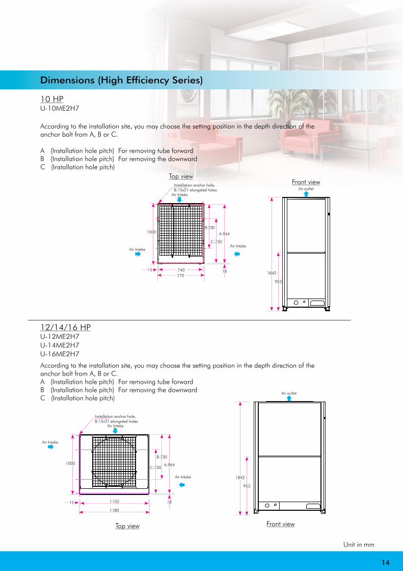
12/14/16 HPU-12ME2H7U-14ME2H7U-16ME2H7
According to the installation site, you may choose the setting position in the depth direction of the anchor bolt from A, B or C.
A (Installation hole pitch) For removing tube forwardB (Installation hole pitch) For removing the downwardC (Installation hole pitch)
10 HPU-10ME2H7
Unit in mm
Top view
1000 A:964
18
B:730
C:730
740770
Air Intake
Air IntakeAir Intake
15
Front view
953
1842
Air outlet
Front view
953
1842
Air outlet
1000
1150
1180
Top view
A:964
18
B:730
C:730
Air Intake
Air Intake
Air Intake
15
According to the installation site, you may choose the setting position in the depth direction of the anchor bolt from A, B or C.A (Installation hole pitch) For removing tube forwardB (Installation hole pitch) For removing the downwardC (Installation hole pitch)
Installation anchor hole, 8-15x21 elongated holes
Dimensions (High Efficiency Series)
Installation anchor hole, 8-15x21 elongated holes
SAIVER S.R.LVia M. da Besozzo,16 20052 Monza (Milan) Italy.Tel : +39. 039. 282 831Fax : +39. 039. 202 5668E-mail : [email protected]: www.saiver.com
SRPC-PDFCE-VRFAHUPAU-Italy-2018.05
SAIVER – Pantone: 2925C 219mmx64mm
Recommended