INTEGRATED PROPULSION SYSTEM NACELLE TECHNOLOGY
DEMONSTRATORCLEEN II Consortium Public Plenary Session
Presenter: Jeff AndersonMay 2nd, 2018
UTC AEROSPACE SYSTEMS NON-CONFIDENTIAL – FOR PUBLIC RELEASE
THIS DOCUMENT DOES NOT CONTAIN ANY EXPORT CONTROLLED TECHNICAL DATA
2
Outline
• Company overview
• Elevator Speech
• Case for Action
• Program Summary
• Opportunity Cost
• Nacelle Technologies
• Technology Risks
• Technology Risk Reduction
• Project Schedule
• Past Achievements
• Future Plans (2018)
• Future Plans (2019)
• Summary
UTC AEROSPACE SYSTEMS NON-CONFIDENTIAL – FOR PUBLIC RELEASE
THIS DOCUMENT DOES NOT CONTAIN ANY EXPORT CONTROLLED TECHNICAL DATA

3
United Technologies
Leading provider of high technology systems for the commercial building and aerospace industries
Employs approximately 220,000 people in more than 4,000 locations
Located in approximately 70 countries around the world
2017 net sales of $60B
UTC AEROSPACE SYSTEMS NON-CONFIDENTIAL – FOR PUBLIC RELEASE
THIS DOCUMENT DOES NOT CONTAIN ANY EXPORT CONTROLLED TECHNICAL DATA
4
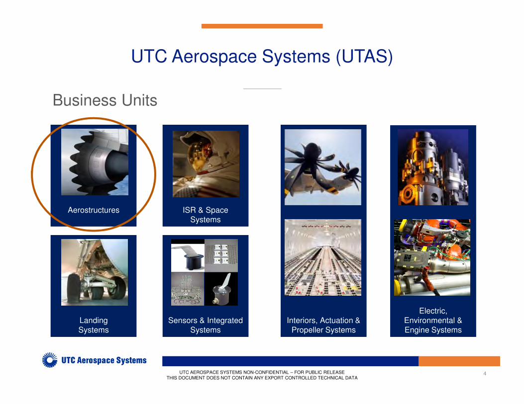
UTC Aerospace Systems (UTAS)
•
Business Units
Electric,
Environmental &
Engine Systems
Electric,
Environmental &
Engine Systems
AerostructuresAerostructures
Interiors, Actuation &
Propeller Systems
Interiors, Actuation &
Propeller Systems
Landing
Systems
Landing
Systems
Sensors & Integrated
Systems
Sensors & Integrated
Systems
ISR & Space
Systems
ISR & Space
Systems
UTC AEROSPACE SYSTEMS NON-CONFIDENTIAL – FOR PUBLIC RELEASE
THIS DOCUMENT DOES NOT CONTAIN ANY EXPORT CONTROLLED TECHNICAL DATA
5
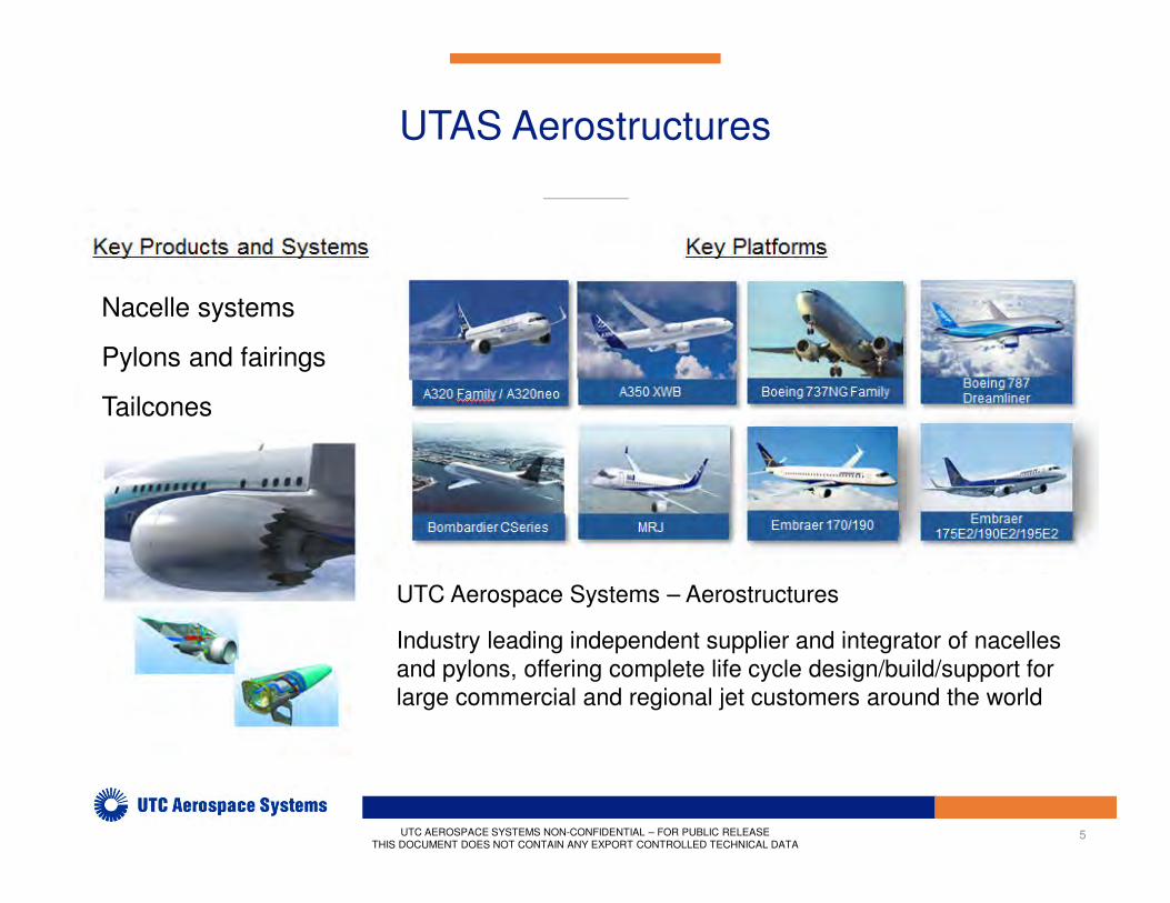
UTAS Aerostructures
•Nacelle systems
Pylons and fairings
Tailcones
UTC Aerospace Systems – Aerostructures
Industry leading independent supplier and integrator of nacelles
and pylons, offering complete life cycle design/build/support for
large commercial and regional jet customers around the world
UTC AEROSPACE SYSTEMS NON-CONFIDENTIAL – FOR PUBLIC RELEASE
THIS DOCUMENT DOES NOT CONTAIN ANY EXPORT CONTROLLED TECHNICAL DATA
6
Elevator Speech
Aerodynamically and acoustically optimized Inlet
and Fan Duct architectures, enabling lower
emissions, energy and noise initiatives, aimed at
maximizing efficiency of the next generation high
bypass ratio propulsion systems for reducing
climate impact from aviation.
UTC AEROSPACE SYSTEMS NON-CONFIDENTIAL – FOR PUBLIC RELEASE
THIS DOCUMENT DOES NOT CONTAIN ANY EXPORT CONTROLLED TECHNICAL DATA
7
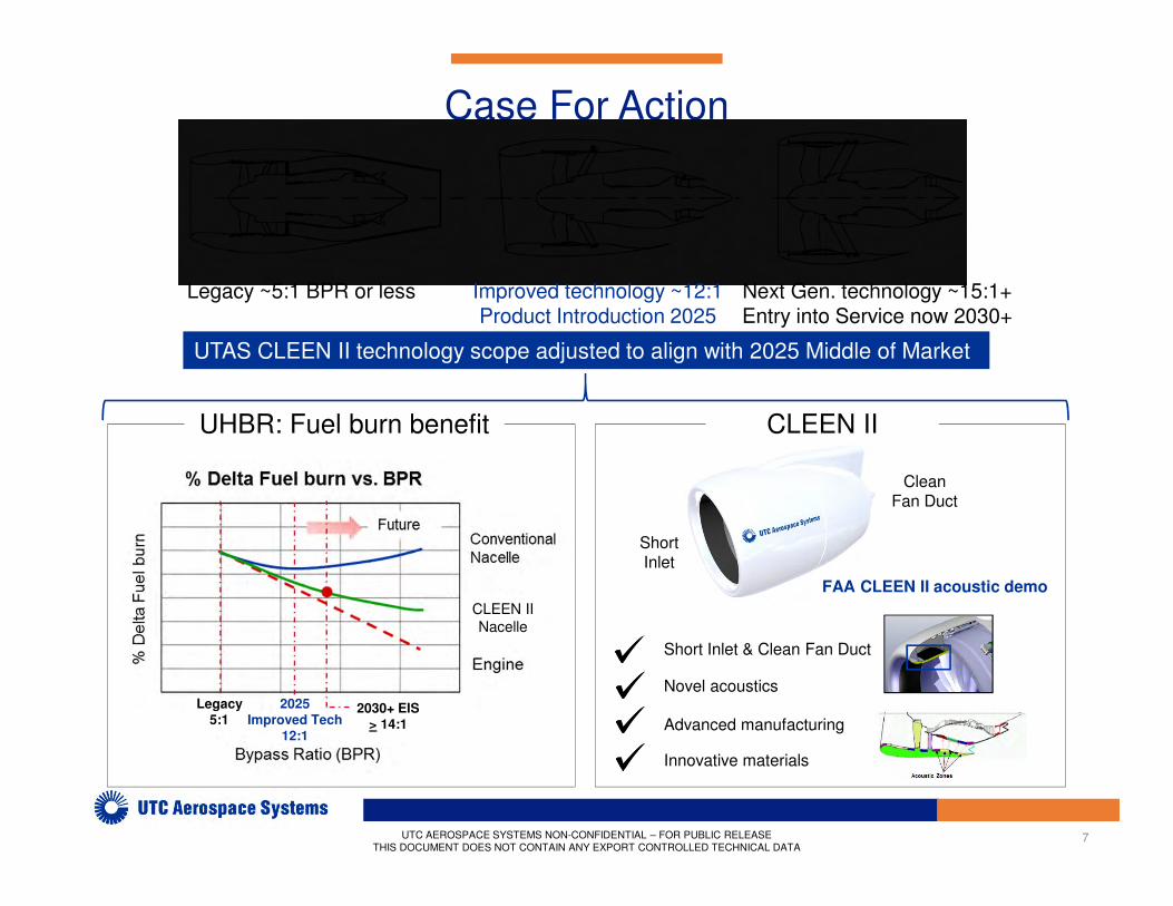
Case For Action
FAA CLEEN II acoustic demo
Innovative materials
Advanced manufacturing
Novel acoustics
UHBR: Fuel burn benefit
Short Inlet & Clean Fan Duct
Legacy ~5:1 BPR or less Improved technology ~12:1Product Introduction 2025
Next Gen. technology ~15:1+Entry into Service now 2030+
UTC AEROSPACE SYSTEMS NON-CONFIDENTIAL – FOR PUBLIC RELEASE
THIS DOCUMENT DOES NOT CONTAIN ANY EXPORT CONTROLLED TECHNICAL DATA
CLEEN II
CLEEN II
Nacelle
2030+ Target
> 14:1
2030+ EIS> 14:1
Legacy5:1
UTAS CLEEN II technology scope adjusted to align with 2025 Middle of Market
2025 Improved Tech
12:1
Short Inlet
CleanFan Duct

8UTC AEROSPACE SYSTEMS NON-CONFIDENTIAL – FOR PUBLIC RELEASE
THIS DOCUMENT DOES NOT CONTAIN ANY EXPORT CONTROLLED TECHNICAL DATA
Risks/Mitigation Plans: • Acoustic performance/subscale tests,
acoustic optimization models
• Load levels & paths, subscale tests,
kinematic & stress model correlation
• Manufacturing tooling and assembly
• Test stand integration/work with P&W
Project Technology
Short Inlet & Clean Fan Duct for HBR Engines
Anticipated Benefits:• -1.0% fuel burn
• -2.0 EPNdB noise
Accomplishments:• FAA ready to proceed with re-scope plan
• Engine platform & test facilities identified
• TRL5 achieved for three technologies
• Ground test conceptual design completeWork Statement:• Develop ground test demonstrator
• Do subscale acoustic and kinematic tests
to validate models
• Perform full-scale engine ground test
• Use test data & analyses to project
aircraft-level benefits
Objectives: • Achieve TRL6 for Clean Fan Duct acoustics
• Achieve TRL5 for HDL & Short Inlet
• Validate anticipated benefits
Short Inlet.6 L/D.4 L/D
TR Zone Liner & HDL
Schedule:
Opportunity Cost
• Fuel burn and noise improvement technologies are important to UTAS future nacelle product competitiveness
• FAA funding: • Accelerates progressions of CLEEN II technologies to TRL6/MRL6
• Supports allocation of IR&D funds to screen and mature more technologies
• Promotes awareness of FAA CLEEN goals within company
• Possible negative impacts without FAA funding:• Delay introduction of these technologies to the commercial fleet
• Defer introduction of other fuel burn/noise technologies
• Unable to offer technologies to 2025 opportunities
10
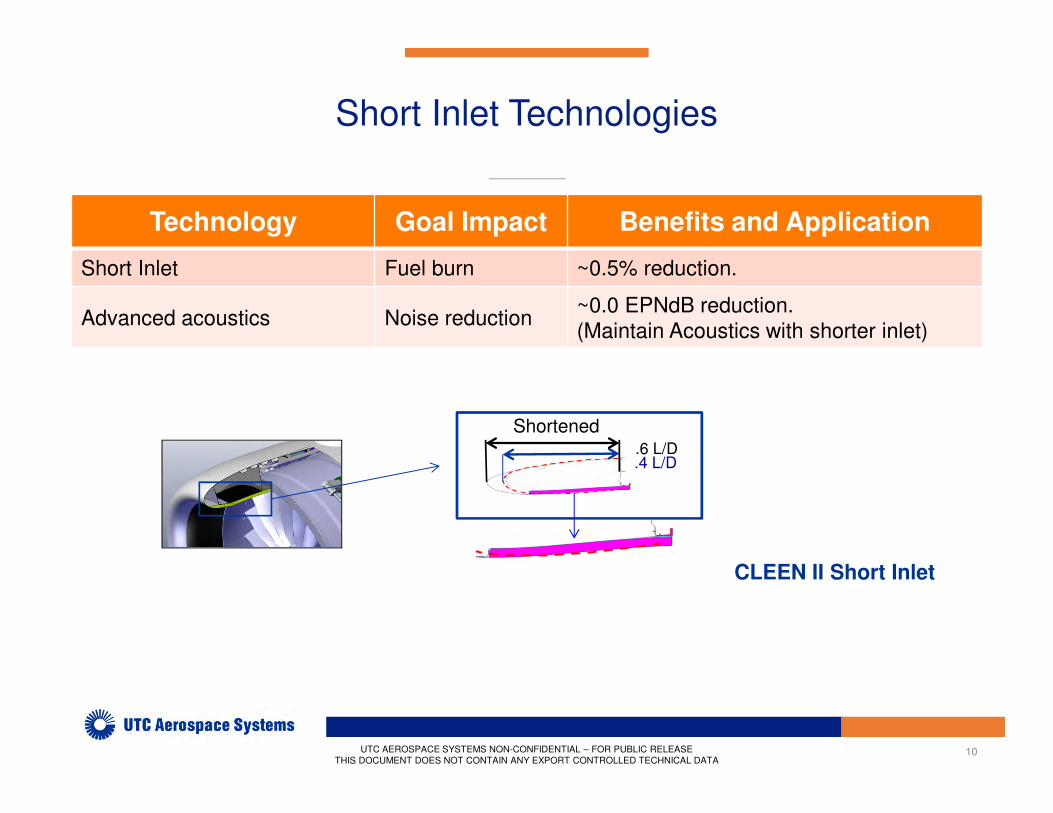
Short Inlet Technologies
CLEEN II Short Inlet
Technology Goal Impact Benefits and Application
Short Inlet Fuel burn ~0.5% reduction.
Advanced acoustics Noise reduction~0.0 EPNdB reduction.
(Maintain Acoustics with shorter inlet)
UTC AEROSPACE SYSTEMS NON-CONFIDENTIAL – FOR PUBLIC RELEASE
THIS DOCUMENT DOES NOT CONTAIN ANY EXPORT CONTROLLED TECHNICAL DATA
Shortened.6 L/D.4 L/D
11
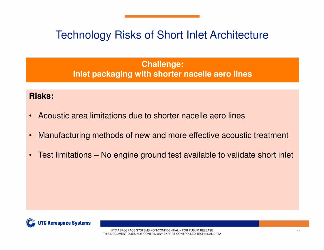
Technology Risks of Short Inlet Architecture
Risks:
• Acoustic area limitations due to shorter nacelle aero lines
• Manufacturing methods of new and more effective acoustic treatment
• Test limitations – No engine ground test available to validate short inlet
UTC AEROSPACE SYSTEMS NON-CONFIDENTIAL – FOR PUBLIC RELEASE
THIS DOCUMENT DOES NOT CONTAIN ANY EXPORT CONTROLLED TECHNICAL DATA
Challenge:Inlet packaging with shorter nacelle aero lines
12
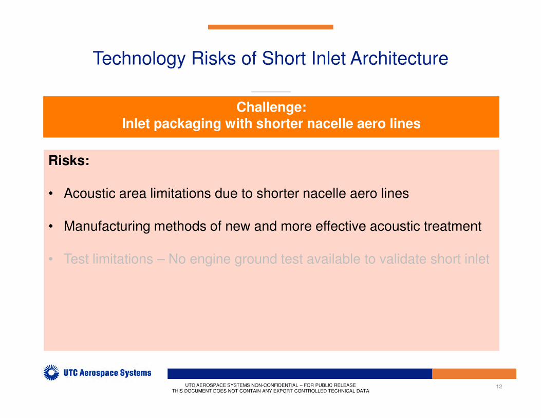
Technology Risks of Short Inlet Architecture
Risks:
• Acoustic area limitations due to shorter nacelle aero lines
• Manufacturing methods of new and more effective acoustic treatment
• Test limitations – No engine ground test available to validate short inlet
UTC AEROSPACE SYSTEMS NON-CONFIDENTIAL – FOR PUBLIC RELEASE
THIS DOCUMENT DOES NOT CONTAIN ANY EXPORT CONTROLLED TECHNICAL DATA
Challenge:Inlet packaging with shorter nacelle aero lines
13
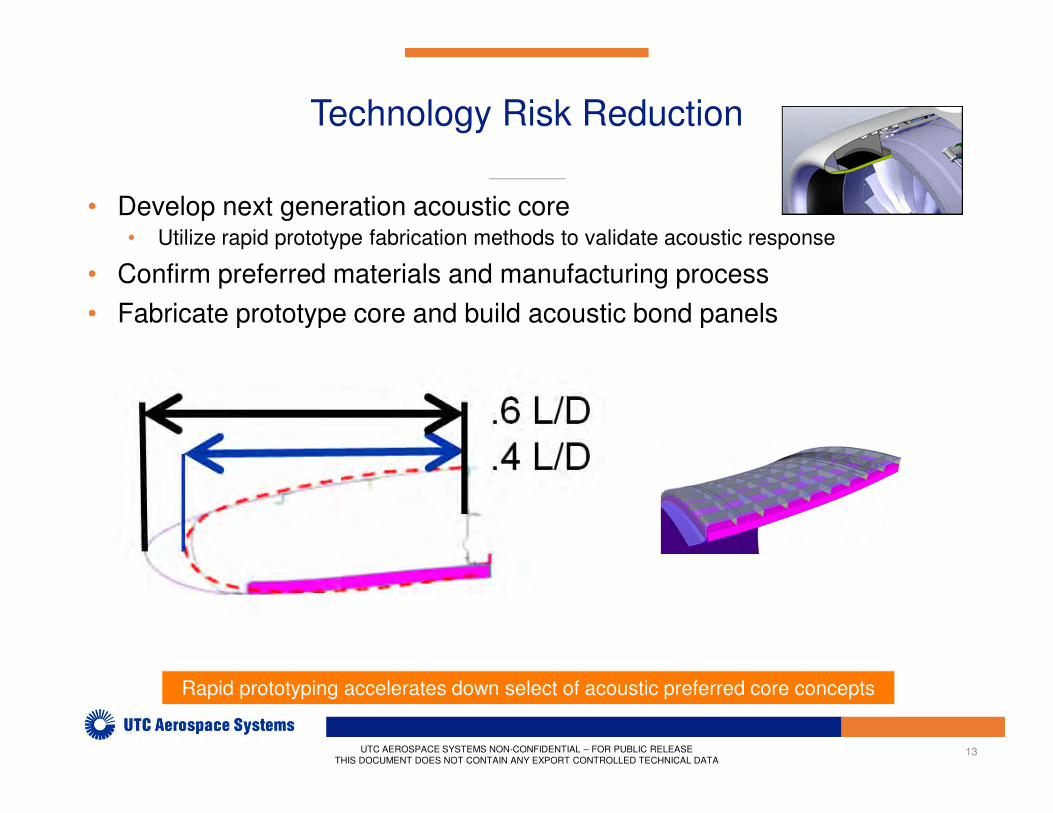
Technology Risk Reduction
UTC AEROSPACE SYSTEMS NON-CONFIDENTIAL – FOR PUBLIC RELEASE
THIS DOCUMENT DOES NOT CONTAIN ANY EXPORT CONTROLLED TECHNICAL DATA
• Develop next generation acoustic core• Utilize rapid prototype fabrication methods to validate acoustic response
• Confirm preferred materials and manufacturing process
• Fabricate prototype core and build acoustic bond panels
Rapid prototyping accelerates down select of acoustic preferred core concepts

14
Technology Risks of Short Inlet Architecture
Risks:
• Acoustic area limitations due to shorter nacelle aero lines
• Manufacturing methods of new and more effective acoustic treatment
• Test limitations – No engine ground test available to validate short inlet
UTC AEROSPACE SYSTEMS NON-CONFIDENTIAL – FOR PUBLIC RELEASE
THIS DOCUMENT DOES NOT CONTAIN ANY EXPORT CONTROLLED TECHNICAL DATA
Challenge:Inlet packaging with shorter nacelle aero lines
15
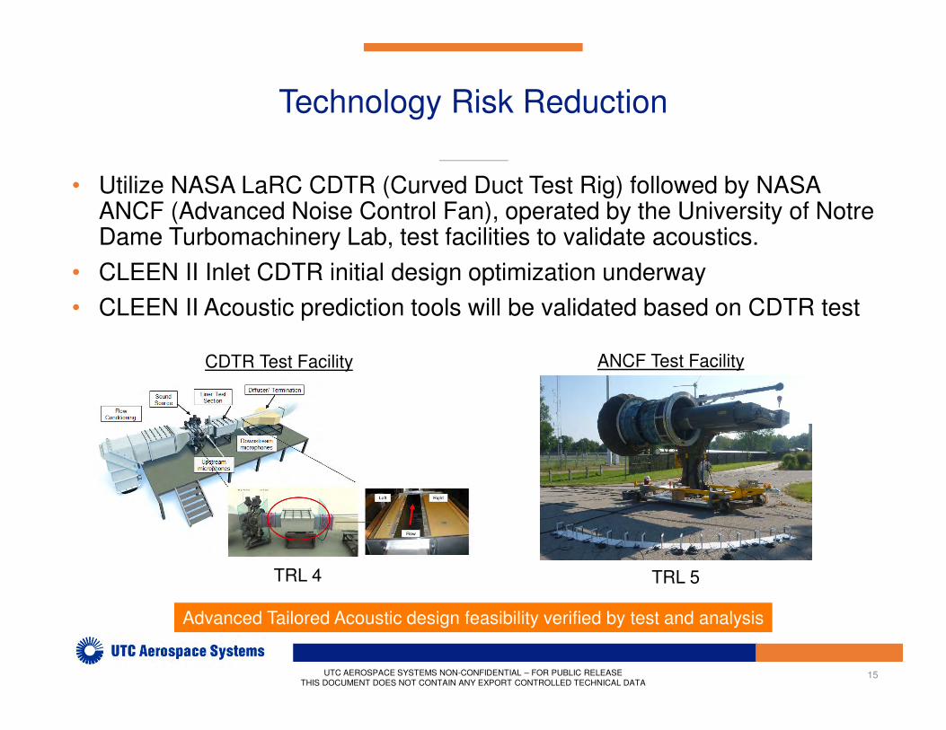
Technology Risk Reduction
UTC AEROSPACE SYSTEMS NON-CONFIDENTIAL – FOR PUBLIC RELEASE
THIS DOCUMENT DOES NOT CONTAIN ANY EXPORT CONTROLLED TECHNICAL DATA
• Utilize NASA LaRC CDTR (Curved Duct Test Rig) followed by NASA ANCF (Advanced Noise Control Fan), operated by the University of Notre Dame Turbomachinery Lab, test facilities to validate acoustics.
• CLEEN II Inlet CDTR initial design optimization underway
• CLEEN II Acoustic prediction tools will be validated based on CDTR test
Advanced Tailored Acoustic design feasibility verified by test and analysis
ANCF Test FacilityCDTR Test Facility
TRL 4 TRL 5

16
Clean Fan Duct Technologies
Technology Goal Impact Benefits and Application
Clean fan duct Thrust
ReverserFuel burn
~0.5% reduction
Demo designed for 25,000-40,000 lb
thrust-class engines with expected entry
into service by 2025
Advanced tailored acoustics Noise reduction~2.0 EPNdB reduction.
(Zoned Acoustics & Area Maximization)
UTC AEROSPACE SYSTEMS NON-CONFIDENTIAL – FOR PUBLIC RELEASE
THIS DOCUMENT DOES NOT CONTAIN ANY EXPORT CONTROLLED TECHNICAL DATA
Low Drag SurfaceZoned/Thin Acoustics &
Area Maximization Fewer Airflow Obstructions
Picture Under Review
For
Public Release
17
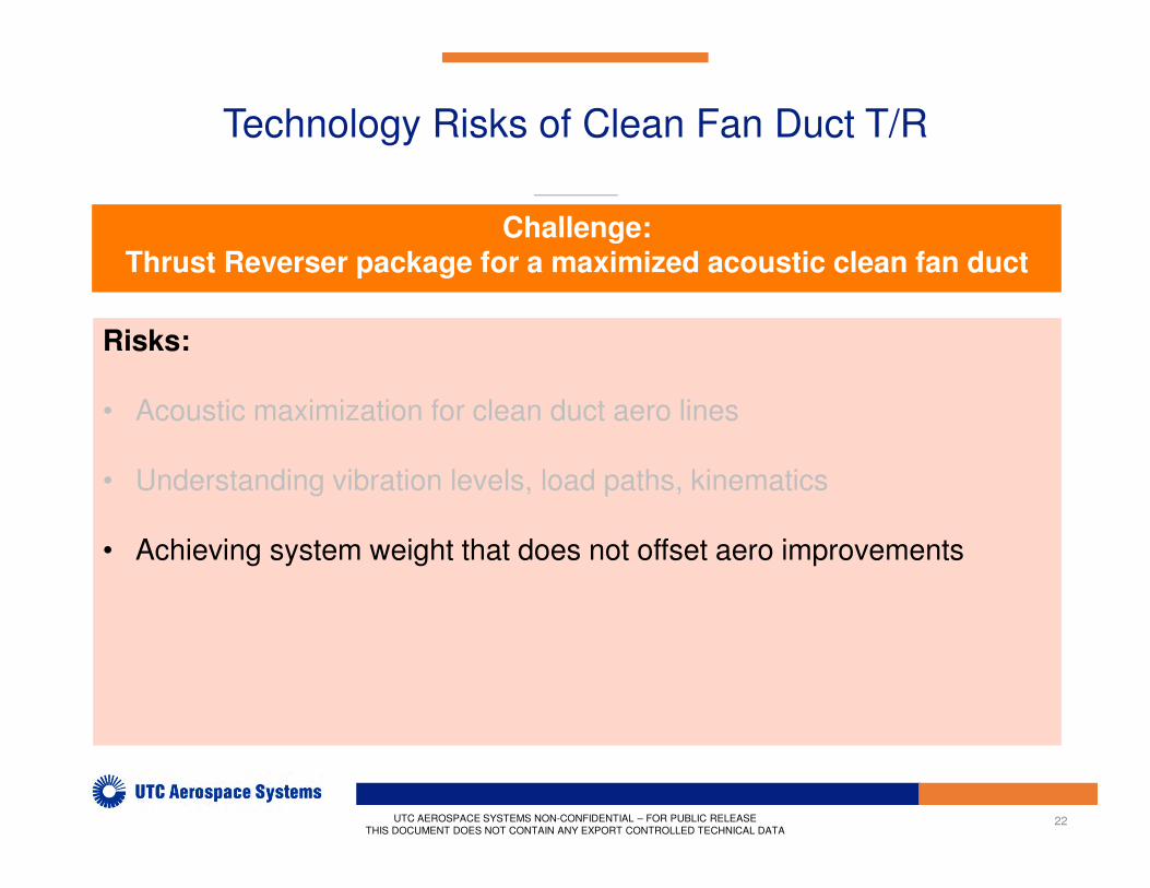
Technology Risks of Clean Fan Duct T/R
Risks:
• Acoustic maximization for clean duct aero lines
• Understanding vibration levels, load paths, kinematics
• Achieving system weight that does not offset aero improvements
UTC AEROSPACE SYSTEMS NON-CONFIDENTIAL – FOR PUBLIC RELEASE
THIS DOCUMENT DOES NOT CONTAIN ANY EXPORT CONTROLLED TECHNICAL DATA
Challenge:Thrust Reverser package for a maximized acoustic clean fan duct

18
Technology Risks of Clean Fan Duct T/R
Risks:
• Acoustic maximization for clean duct aero lines
• Understanding vibration levels, load paths, kinematics
• Achieving system weight that does not offset aero improvements
UTC AEROSPACE SYSTEMS NON-CONFIDENTIAL – FOR PUBLIC RELEASE
THIS DOCUMENT DOES NOT CONTAIN ANY EXPORT CONTROLLED TECHNICAL DATA
Challenge:Thrust Reverser package for a maximized acoustic clean fan duct
19
Technology Risk Reduction
UTC AEROSPACE SYSTEMS NON-CONFIDENTIAL – FOR PUBLIC RELEASE
THIS DOCUMENT DOES NOT CONTAIN ANY EXPORT CONTROLLED TECHNICAL DATA
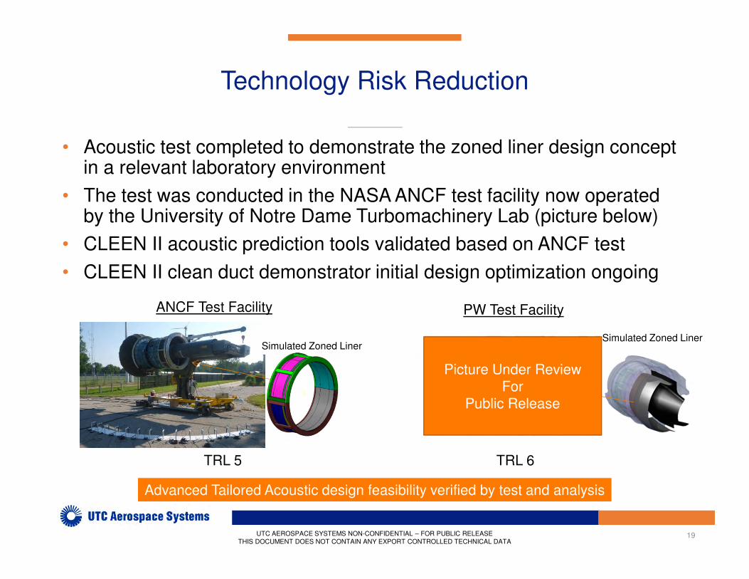
• Acoustic test completed to demonstrate the zoned liner design concept in a relevant laboratory environment
• The test was conducted in the NASA ANCF test facility now operated by the University of Notre Dame Turbomachinery Lab (picture below)
• CLEEN II acoustic prediction tools validated based on ANCF test
• CLEEN II clean duct demonstrator initial design optimization ongoing
Simulated Zoned Liner
ANCF Test Facility
Advanced Tailored Acoustic design feasibility verified by test and analysis
PW Test Facility
Simulated Zoned Liner
TRL 5 TRL 6
Picture Under Review
For
Public Release
20
Technology Risks of Clean Fan Duct T/R
Risks:
• Acoustic maximization for clean duct aero lines
• Understanding vibration levels, load paths, kinematics
• Achieving system weight that does not offset aero improvements
UTC AEROSPACE SYSTEMS NON-CONFIDENTIAL – FOR PUBLIC RELEASE
THIS DOCUMENT DOES NOT CONTAIN ANY EXPORT CONTROLLED TECHNICAL DATA
Challenge:Thrust Reverser package for a maximized acoustic clean fan duct
21
Technology Risk Reduction
UTC AEROSPACE SYSTEMS NON-CONFIDENTIAL – FOR PUBLIC RELEASE
THIS DOCUMENT DOES NOT CONTAIN ANY EXPORT CONTROLLED TECHNICAL DATA
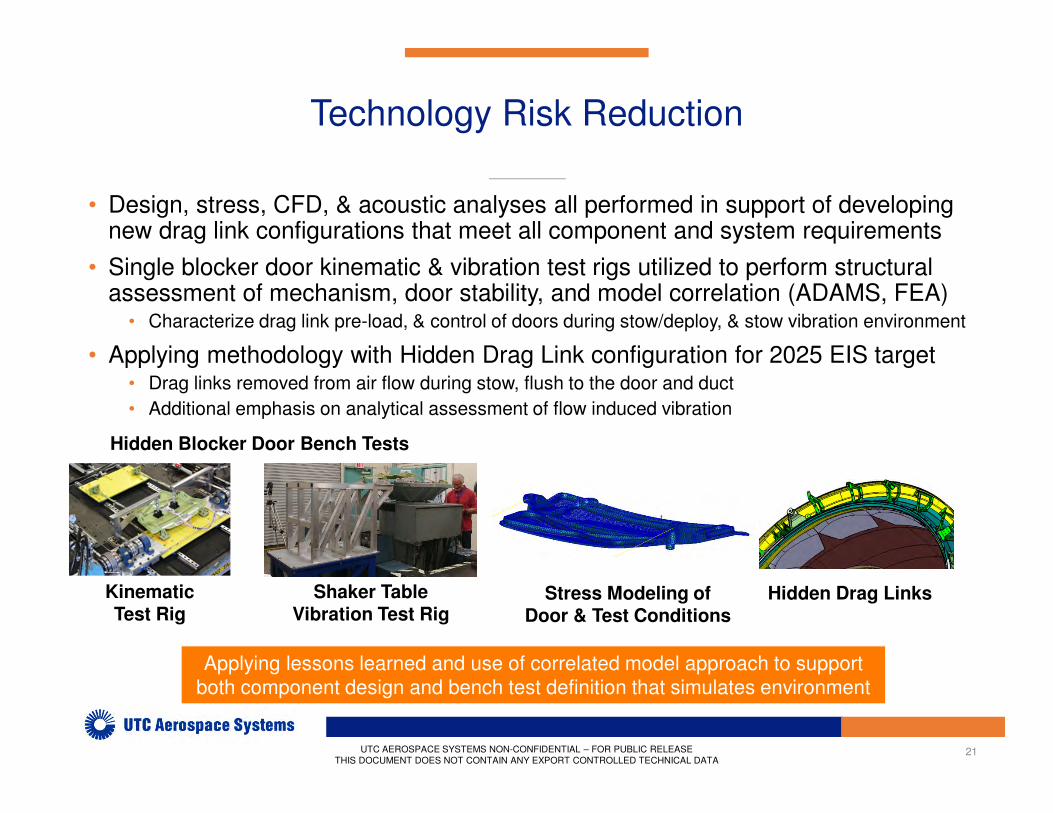
• Design, stress, CFD, & acoustic analyses all performed in support of developing new drag link configurations that meet all component and system requirements
• Single blocker door kinematic & vibration test rigs utilized to perform structural assessment of mechanism, door stability, and model correlation (ADAMS, FEA)
• Characterize drag link pre-load, & control of doors during stow/deploy, & stow vibration environment
• Applying methodology with Hidden Drag Link configuration for 2025 EIS target• Drag links removed from air flow during stow, flush to the door and duct
• Additional emphasis on analytical assessment of flow induced vibration
Shaker Table Vibration Test Rig
Kinematic Test Rig
Applying lessons learned and use of correlated model approach to support
both component design and bench test definition that simulates environment
Stress Modeling of Door & Test Conditions
Hidden Drag Links
Hidden Blocker Door Bench Tests
22
Technology Risks of Clean Fan Duct T/R
Risks:
• Acoustic maximization for clean duct aero lines
• Understanding vibration levels, load paths, kinematics
• Achieving system weight that does not offset aero improvements
UTC AEROSPACE SYSTEMS NON-CONFIDENTIAL – FOR PUBLIC RELEASE
THIS DOCUMENT DOES NOT CONTAIN ANY EXPORT CONTROLLED TECHNICAL DATA
Challenge:Thrust Reverser package for a maximized acoustic clean fan duct
23
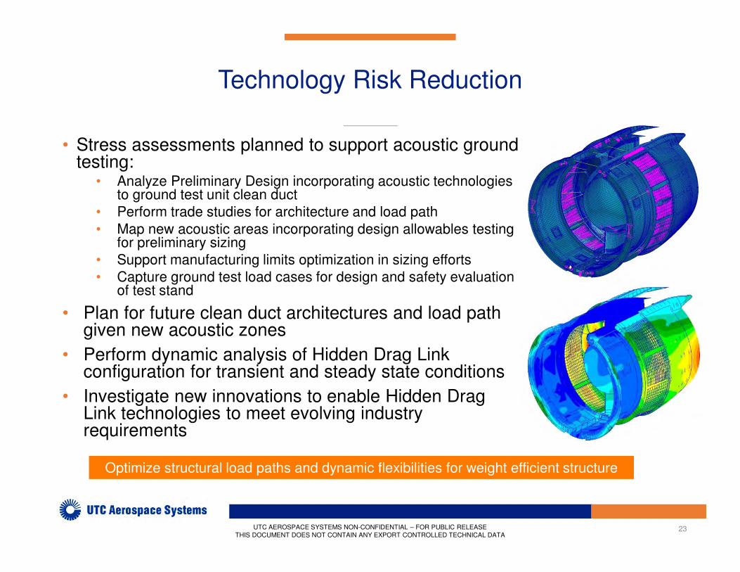
Technology Risk Reduction
UTC AEROSPACE SYSTEMS NON-CONFIDENTIAL – FOR PUBLIC RELEASE
THIS DOCUMENT DOES NOT CONTAIN ANY EXPORT CONTROLLED TECHNICAL DATA
• Stress assessments planned to support acoustic ground testing:
• Analyze Preliminary Design incorporating acoustic technologies to ground test unit clean duct
• Perform trade studies for architecture and load path
• Map new acoustic areas incorporating design allowables testing for preliminary sizing
• Support manufacturing limits optimization in sizing efforts
• Capture ground test load cases for design and safety evaluation of test stand
• Plan for future clean duct architectures and load path given new acoustic zones
• Perform dynamic analysis of Hidden Drag Link configuration for transient and steady state conditions
• Investigate new innovations to enable Hidden Drag Link technologies to meet evolving industry requirements
Optimize structural load paths and dynamic flexibilities for weight efficient structure
24
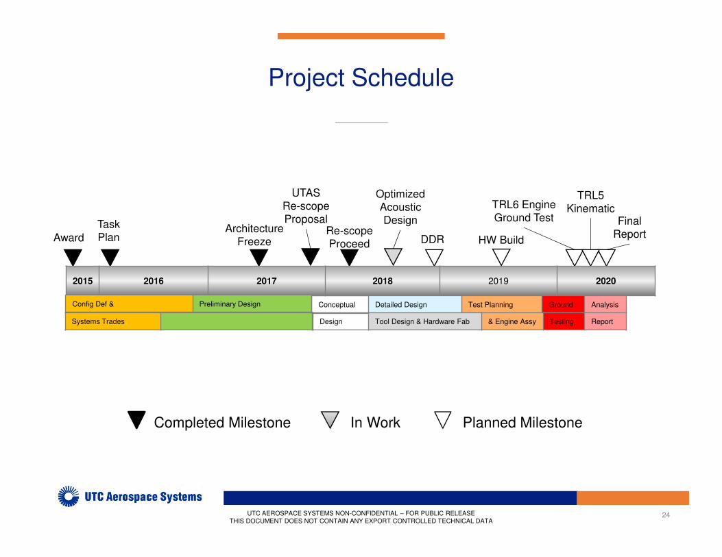
Project Schedule
Planned MilestoneCompleted Milestone
UTC AEROSPACE SYSTEMS NON-CONFIDENTIAL – FOR PUBLIC RELEASE
THIS DOCUMENT DOES NOT CONTAIN ANY EXPORT CONTROLLED TECHNICAL DATA
In Work
Award
Task
PlanRe-scope
Proceed DDR
TRL6 Engine
Ground Test Final
Report
TRL5
Kinematic
Architecture
Freeze
2015 2016 2017 2018 2019 2020
HW Build
Optimized
Acoustic
Design
UTAS
Re-scope
Proposal
Config Def & Preliminary Design
Systems Trades
Conceptual Detailed Design Test Planning Ground Analysis
Design Tool Design & Hardware Fab & Engine Assy Testing Report
25
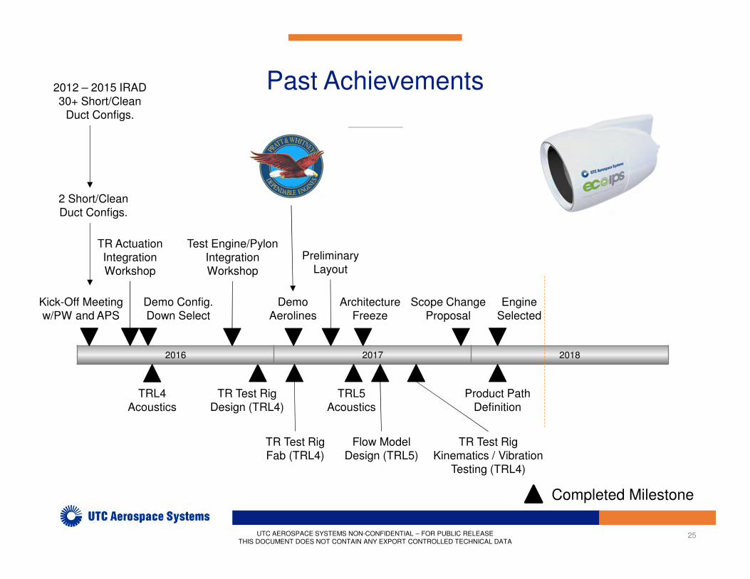
Past Achievements
2016 2017 2018
Demo Config.
Down Select
Test Engine/Pylon
Integration
Workshop
TRL4
Acoustics
TR Test Rig
Design (TRL4)
2 Short/Clean
Duct Configs.
2012 – 2015 IRAD
30+ Short/Clean
Duct Configs.
Kick-Off Meeting
w/PW and APS
TR Actuation
Integration
Workshop
Completed Milestone
UTC AEROSPACE SYSTEMS NON-CONFIDENTIAL – FOR PUBLIC RELEASE
THIS DOCUMENT DOES NOT CONTAIN ANY EXPORT CONTROLLED TECHNICAL DATA
Demo
Aerolines
TR Test Rig
Fab (TRL4)
Preliminary
Layout
Architecture
Freeze
Flow Model
Design (TRL5)
TRL5
Acoustics
TR Test Rig
Kinematics / Vibration
Testing (TRL4)
Scope Change
Proposal
Engine
Selected
Product Path
Definition

26
Future Plans (2018)
Q1 Q2 Q3 Q4
Test Rig
Design
Layout
Engine
Selected
Linkless
Blocker Door
Configuration
Downselect
Preliminary
Design &
Analysis
Clean Duct
Conceptual
Design
Product Path
Definition
Test Rig
Design &
Planning
DDR
Planned MilestoneCompleted Milestone
UTC AEROSPACE SYSTEMS NON-CONFIDENTIAL – FOR PUBLIC RELEASE
THIS DOCUMENT DOES NOT CONTAIN ANY EXPORT CONTROLLED TECHNICAL DATA
Initial Assembly
Drawings
Test Rig
Stress & Aero
Analysis
27
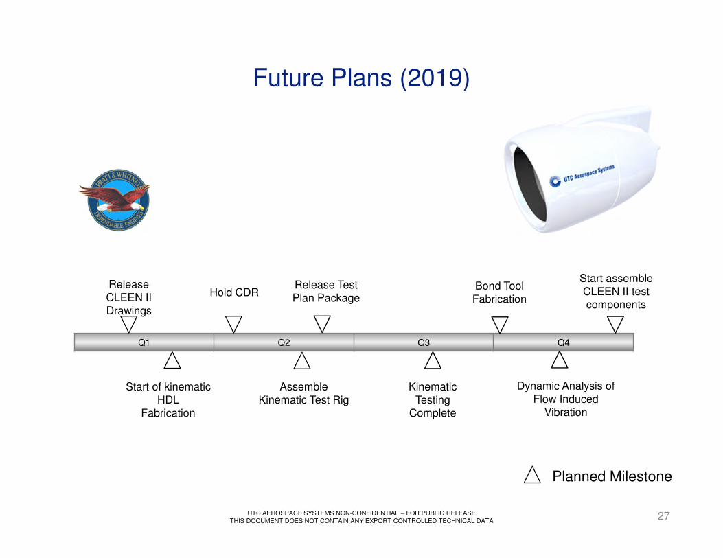
Future Plans (2019)
Q1 Q2 Q3 Q4
Planned Milestone
UTC AEROSPACE SYSTEMS NON-CONFIDENTIAL – FOR PUBLIC RELEASE
THIS DOCUMENT DOES NOT CONTAIN ANY EXPORT CONTROLLED TECHNICAL DATA
Release
CLEEN II
Drawings
Start assemble
CLEEN II test
components
Release Test
Plan PackageHold CDR
Kinematic
Testing
Complete
Bond Tool
Fabrication
Assemble
Kinematic Test Rig
Start of kinematic
HDL
Fabrication
Dynamic Analysis of
Flow Induced
Vibration
28
Summary
• Re-scope meets 2025 next generation technology needs
• Aimed at maximizing efficiency of 2025 high bypass ratio propulsion systems
• Technologies applicable for next generation nacelles for Next Generation Single Aisle, New Midsize Airplane, Middle of the Market
• Inlet & T/R architectures support CLEEN II lower energy and noise initiatives
• Ground Test demonstrator conceptual design frozen
• Selected technologies applicable for performance insertion on current production programs
UTC AEROSPACE SYSTEMS NON-CONFIDENTIAL – FOR PUBLIC RELEASE
THIS DOCUMENT DOES NOT CONTAIN ANY EXPORT CONTROLLED TECHNICAL DATA
Thanks!
Any Questions?
29UTC AEROSPACE SYSTEMS NON-CONFIDENTIAL – FOR PUBLIC RELEASE
THIS DOCUMENT DOES NOT CONTAIN ANY EXPORT CONTROLLED TECHNICAL DATA
Recommended