Chalcogenide Letters Vol. 12, No. 6, June 2015, p. 301 - 312
INFLUENCE OF HUBBARD COEFFICIENT ON THE STRUCTURAL,
ELECTRONIC, MAGNETIC AND OPTICAL PROPERTIES OF Mn/Fe
CODOPED ZnS
A. ABBAD
a*, H. A. BENTOUNES
a, W. BENSTAALI
b, S. BENTATA
b,
B. BOUADJEMIb
aSignals and Systems Laboratory (LSS), Faculty of Sciences and Technology,
BP227, Abdelhamid Ibn Badis University, Mostaganem (27000) Algeria bLaboratory of Technology and Solids Properties, Faculty of Sciences and
Technology, BP227, Abdelhamid Ibn Badis University, Mostaganem (27000)
Algeria
We have investigated the structural, electronic and magnetic properties of substitutional
iron and manganese transition metal impurities in wurtzite ZnFeMnS by employing the ab-
initio method. Calculations were performed by using the full potential linearized
augmented plane wave (FPLAPW) method within the framework of spin-polarized density
functional theory (DFT). The electronic exchange correlation energy is described by
generalized gradient approximation GGA and GGA+U (where U is the Hubbard
correction). The GGA+U method is applied to iron 3d states. We have calculated the
lattice parameters, bulk modulus, the first pressure derivative of the bulk modulus and the
cohesive energies. The calculated densities of states presented in this study identify the
half-metallic behavior of ZnFeMnS when we use the GGA+U scheme with spin up
channels metallic and spin down ones semiconducting. The half-metallicity depends
strongly on the value of Hubbard coefficient U until the critical value of 8 eV.
Furthermore, we have calculated optical properties, and found interesting results.
(Received May 8, 2015; Accepted June 12, 2015)
Keywords: Semiconductors; First Principle calculations; half-metallic; Magnetic
properties; Optical properties
1. Introduction Recently, diluted magnetic semiconductors (DMSs) have gained much attention due to the
possibility of having magnetic properties. The DMS are III–V, II–VI, II–IV or IV–VI alloys in
which cations are randomly substituted by the magnetic ions from the series of transition metals
(such as Cr, Mn, Fe, Co or Ni). Research into diluted magnetic semiconductors (DMSs) has been
motivated due to the opportunity of manipulating the electron spin in semiconducting devices as
the base for the applications of spintronics [1, 2], which is the potential second-generation
electronics, that focuses on the transmission of both charge and spin of electrons [3, 4]. It has
additional extensive application foreground than microelectronics (the first generation electronics
that only studies charges of electrons). More recently, there has been increasing interest in the
spintronic materials, especially the half-metallic ferromagnets (HMFs) which have a 100% spin-
polarization at the Fermi level. The concept of a HMF was introduced by de Groot et al. [5]. So
far, there have been so many researches, both theoretically and experimentally, to find new half-
metallic ferromagnets. Some of the materials that are approved to be half-metal theoretically or
experimentally are Heusler compounds [6- 12], ferromagnetic metallic oxides [13-19], dilute
magnetic semiconductors [20- 26] and zincblende transition-metal pnictides and chalcogenides
[27- 31].
*Corresponding author: [email protected]
302
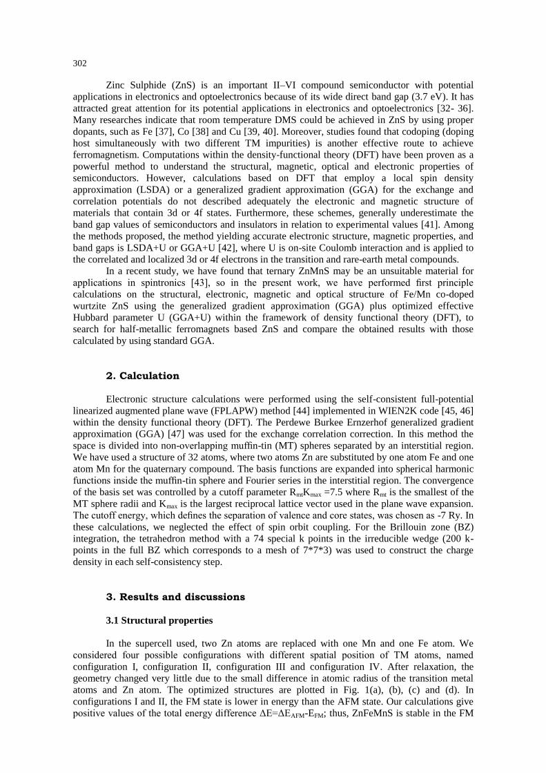
Zinc Sulphide (ZnS) is an important II–VI compound semiconductor with potential
applications in electronics and optoelectronics because of its wide direct band gap (3.7 eV). It has
attracted great attention for its potential applications in electronics and optoelectronics [32- 36].
Many researches indicate that room temperature DMS could be achieved in ZnS by using proper
dopants, such as Fe [37], Co [38] and Cu [39, 40]. Moreover, studies found that codoping (doping
host simultaneously with two different TM impurities) is another effective route to achieve
ferromagnetism. Computations within the density-functional theory (DFT) have been proven as a
powerful method to understand the structural, magnetic, optical and electronic properties of
semiconductors. However, calculations based on DFT that employ a local spin density
approximation (LSDA) or a generalized gradient approximation (GGA) for the exchange and
correlation potentials do not described adequately the electronic and magnetic structure of
materials that contain 3d or 4f states. Furthermore, these schemes, generally underestimate the
band gap values of semiconductors and insulators in relation to experimental values [41]. Among
the methods proposed, the method yielding accurate electronic structure, magnetic properties, and
band gaps is LSDA+U or GGA+U [42], where U is on-site Coulomb interaction and is applied to
the correlated and localized 3d or 4f electrons in the transition and rare-earth metal compounds.
In a recent study, we have found that ternary ZnMnS may be an unsuitable material for
applications in spintronics [43], so in the present work, we have performed first principle
calculations on the structural, electronic, magnetic and optical structure of Fe/Mn co-doped
wurtzite ZnS using the generalized gradient approximation (GGA) plus optimized effective
Hubbard parameter U (GGA+U) within the framework of density functional theory (DFT), to
search for half-metallic ferromagnets based ZnS and compare the obtained results with those
calculated by using standard GGA.
2. Calculation
Electronic structure calculations were performed using the self-consistent full-potential
linearized augmented plane wave (FPLAPW) method [44] implemented in WIEN2K code [45, 46]
within the density functional theory (DFT). The Perdewe Burkee Ernzerhof generalized gradient
approximation (GGA) [47] was used for the exchange correlation correction. In this method the
space is divided into non-overlapping muffin-tin (MT) spheres separated by an interstitial region.
We have used a structure of 32 atoms, where two atoms Zn are substituted by one atom Fe and one
atom Mn for the quaternary compound. The basis functions are expanded into spherical harmonic
functions inside the muffin-tin sphere and Fourier series in the interstitial region. The convergence
of the basis set was controlled by a cutoff parameter RmtKmax =7.5 where Rmt is the smallest of the
MT sphere radii and Kmax is the largest reciprocal lattice vector used in the plane wave expansion.
The cutoff energy, which defines the separation of valence and core states, was chosen as -7 Ry. In
these calculations, we neglected the effect of spin orbit coupling. For the Brillouin zone (BZ)
integration, the tetrahedron method with a 74 special k points in the irreducible wedge (200 k-
points in the full BZ which corresponds to a mesh of 7*7*3) was used to construct the charge
density in each self-consistency step.
3. Results and discussions
3.1 Structural properties
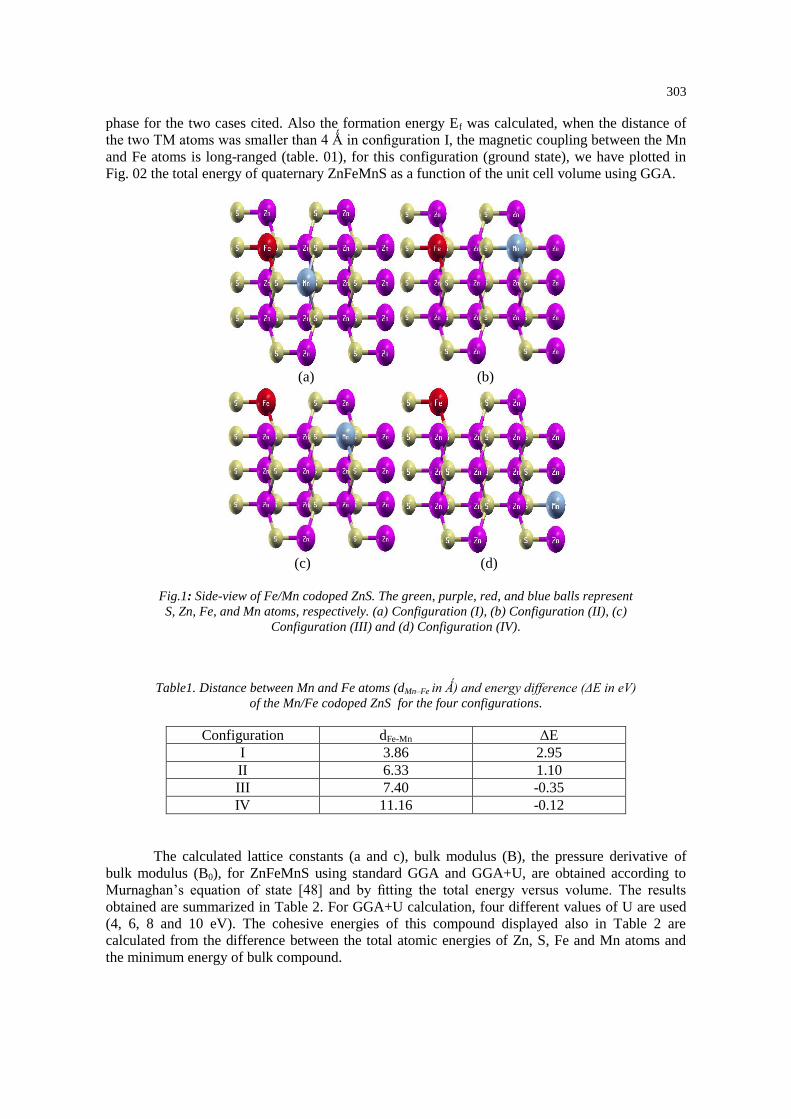
In the supercell used, two Zn atoms are replaced with one Mn and one Fe atom. We
considered four possible configurations with different spatial position of TM atoms, named
configuration I, configuration II, configuration III and configuration IV. After relaxation, the
geometry changed very little due to the small difference in atomic radius of the transition metal
atoms and Zn atom. The optimized structures are plotted in Fig. 1(a), (b), (c) and (d). In
configurations I and II, the FM state is lower in energy than the AFM state. Our calculations give
positive values of the total energy difference ΔE=ΔEAFM-EFM; thus, ZnFeMnS is stable in the FM
303
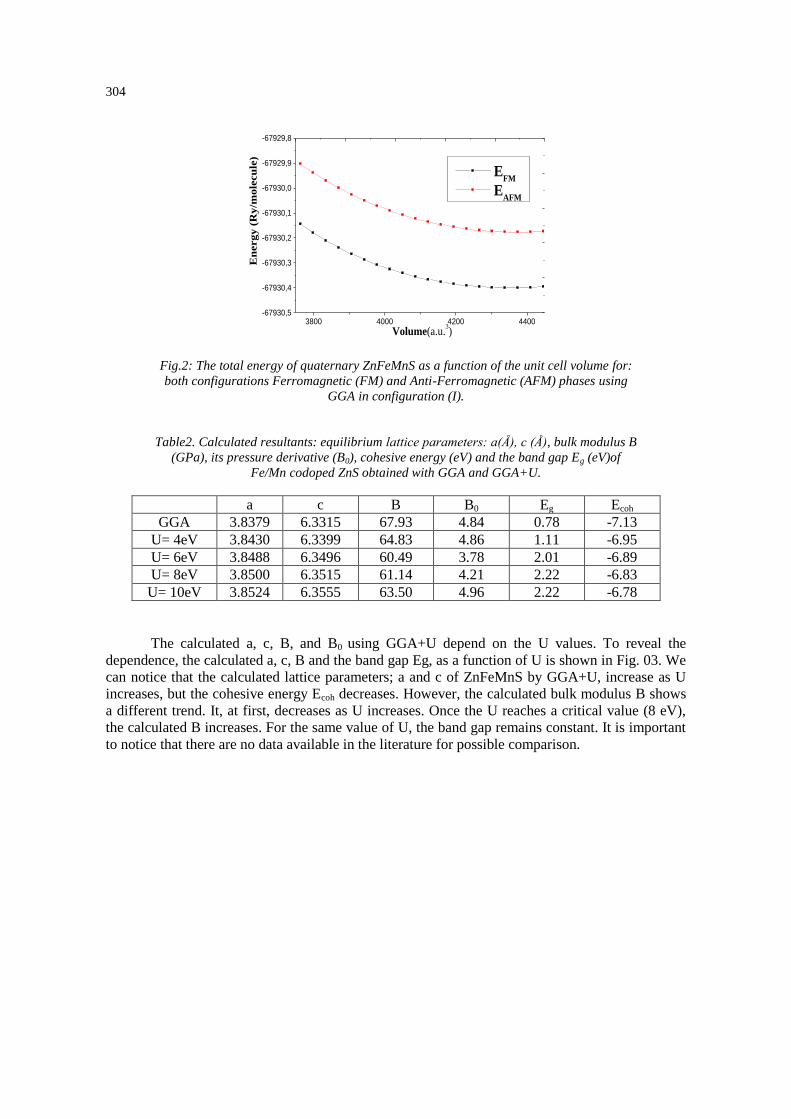
phase for the two cases cited. Also the formation energy Ef was calculated, when the distance of
the two TM atoms was smaller than 4 Ǻ in configuration I, the magnetic coupling between the Mn
and Fe atoms is long-ranged (table. 01), for this configuration (ground state), we have plotted in
Fig. 02 the total energy of quaternary ZnFeMnS as a function of the unit cell volume using GGA.
(a) (b)
(c) (d)
Fig.1: Side-view of Fe/Mn codoped ZnS. The green, purple, red, and blue balls represent
S, Zn, Fe, and Mn atoms, respectively. (a) Configuration (I), (b) Configuration (II), (c)
Configuration (III) and (d) Configuration (IV).
Table1. Distance between Mn and Fe atoms (dMn–Fe in Ǻ) and energy difference (ΔE in eV)
of the Mn/Fe codoped ZnS for the four configurations.
Configuration dFe-Mn ΔE
I 3.86 2.95
II 6.33 1.10
III 7.40 -0.35
IV 11.16 -0.12
The calculated lattice constants (a and c), bulk modulus (B), the pressure derivative of
bulk modulus (B0), for ZnFeMnS using standard GGA and GGA+U, are obtained according to
Murnaghan’s equation of state [48] and by fitting the total energy versus volume. The results
obtained are summarized in Table 2. For GGA+U calculation, four different values of U are used
(4, 6, 8 and 10 eV). The cohesive energies of this compound displayed also in Table 2 are
calculated from the difference between the total atomic energies of Zn, S, Fe and Mn atoms and
the minimum energy of bulk compound.
304
3800 4000 4200 4400-67930,5
-67930,4
-67930,3
-67930,2
-67930,1
-67930,0
-67929,9
-67929,8
EFM
EAFM
En
ergy
(R
y/m
ole
cu
le)
Volume(a.u.3)
Fig.2: The total energy of quaternary ZnFeMnS as a function of the unit cell volume for:
both configurations Ferromagnetic (FM) and Anti-Ferromagnetic (AFM) phases using
GGA in configuration (I).
Table2. Calculated resultants: equilibrium lattice parameters: a(Å), c (Å), bulk modulus B
(GPa), its pressure derivative (B0), cohesive energy (eV) and the band gap Eg (eV)of
Fe/Mn codoped ZnS obtained with GGA and GGA+U.
a c B B0 Eg Ecoh
GGA 3.8379 6.3315 67.93 4.84 0.78 -7.13
U= 4eV 3.8430 6.3399 64.83 4.86 1.11 -6.95
U= 6eV 3.8488 6.3496 60.49 3.78 2.01 -6.89
U= 8eV 3.8500 6.3515 61.14 4.21 2.22 -6.83
U= 10eV 3.8524 6.3555 63.50 4.96 2.22 -6.78
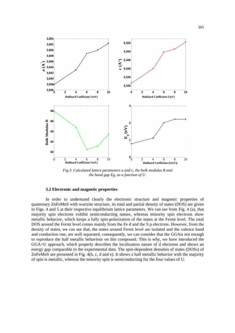
The calculated a, c, B, and B0 using GGA+U depend on the U values. To reveal the
dependence, the calculated a, c, B and the band gap Eg, as a function of U is shown in Fig. 03. We
can notice that the calculated lattice parameters; a and c of ZnFeMnS by GGA+U, increase as U
increases, but the cohesive energy Ecoh decreases. However, the calculated bulk modulus B shows
a different trend. It, at first, decreases as U increases. Once the U reaches a critical value (8 eV),
the calculated B increases. For the same value of U, the band gap remains constant. It is important
to notice that there are no data available in the literature for possible comparison.
305
0 2 4 6 8 103,836
3,838
3,840
3,842
3,844
3,846
3,848
3,850
3,852
3,854
a (
A° )
Hubbard Coefficient U(eV)
0 2 4 6 8 10
6,330
6,335
6,340
6,345
6,350
6,355
Hubbard Coefficient U(eV)
c (
A°)
0 2 4 6 8 10
60
62
64
66
68
Hubbard Coefficient U(eV)
Bu
lk M
od
ulu
s B
0 2 4 6 8 100
1
2
3
Hubbard Coefficient (U(eV))
Eg (
eV
)
Fig.3. Calculated lattice parameters a and c, the bulk modulus B and
the band gap Eg, as a function of U.
3.2 Electronic and magnetic properties
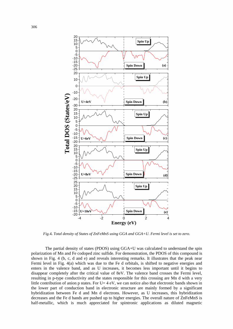
In order to understand clearly the electronic structure and magnetic properties of
quaternary ZnFeMnS with wurtzite structure, its total and partial density of states (DOS) are given
in Figs. 4 and 5 at their respective equilibrium lattice parameters. We can see from Fig. 4 (a), that
majority spin electrons exhibit semiconducting nature, whereas minority spin electrons show
metallic behavior, which keeps a fully spin-polarization of the states at the Fermi level. The total
DOS around the Fermi level comes mainly from the Fe d and the S p electrons. However, from the
density of states, we can see that, the states around Fermi level are isolated and the valence band
and conduction one, are well separated, consequently, we can consider that the GGAis not enough
to reproduce the half metallic behaviour on this compound. This is why, we have introduced the
GGA+U approach, which properly describes the localization nature of d electrons and shows an
energy gap comparable to the experimental data. The spin-dependent densities of states (DOSs) of
ZnFeMnS are presented in Fig. 4(b, c, d and e). It shows a half metallic behavior with the majority
of spin is metallic, whereas the minority spin is semiconducting for the four values of U.
306
-4 -2 0 2 4-20-15-10-505
10152025
(e)U=10eV
Spin Up
Spin Down
Energy (eV)
-25-20-15-10-505
101520
(d)U=8eV
Spin Up
-20
-15
-10
-5
0
5
10
15
20
(c)U=6eV Spin Down
Spin Up
To
tal
DO
S (
Sta
tes/
eV)
-30
-20
-10
0
10
20
(b)Spin Down
Spin Up
-25-20-15-10-505
101520
(a)
U=4eV
Spin Down
Spin Up
Spin Down
Fig.4. Total density of States of ZnFeMnS using GGA and GGA+U. Fermi level is set to zero.
The partial density of states (PDOS) using GGA+U was calculated to understand the spin
polarization of Mn and Fe codoped zinc sulfide. For demonstration, the PDOS of this compound is
shown in Fig. 4 (b, c, d and e) and reveals interesting remarks. It illustrates that the peak near
Fermi level in Fig. 4(a) which was due to the Fe d orbitals, is shifted to negative energies and
enters in the valence band, and as U increases, it becomes less important until it begins to
disappear completely after the critical value of 8eV. The valence band crosses the Fermi level,
resulting in p-type conductivity and the states responsible for this crossing are Mn d with a very
little contribution of anion p states. For U= 4 eV, we can notice also that electronic bands shown in
the lower part of conduction band in electronic structure are mainly formed by a significant
hybridization between Fe d and Mn d electrons. However, as U increases, this hybridization
decreases and the Fe d bands are pushed up to higher energies. The overall nature of ZnFeMnS is
half-metallic, which is much appreciated for spintronic applications as diluted magnetic
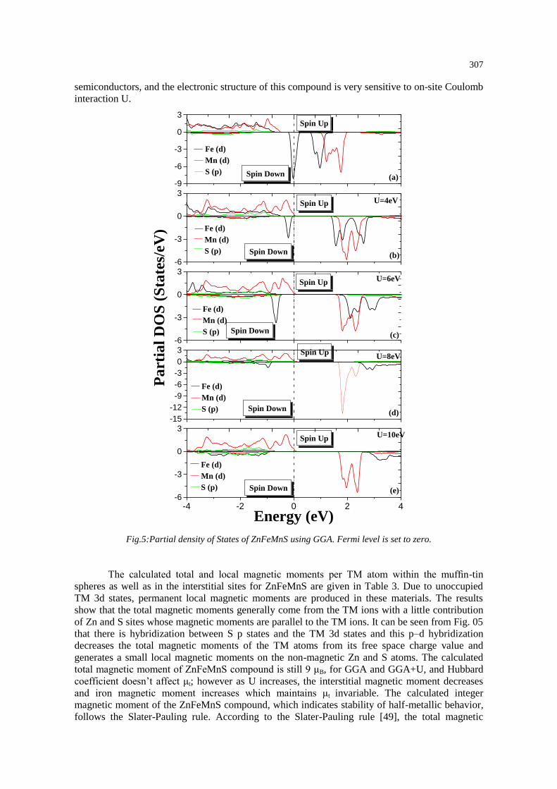
307
semiconductors, and the electronic structure of this compound is very sensitive to on-site Coulomb
interaction U.
-4 -2 0 2 4-6
-3
0
3U=10eV
(e)
Spin Up
Spin Down
Fe (d)
Mn (d)
S (p)
Energy (eV)
-15
-12
-9
-6
-3
0
3U=8eV
(d)Spin Down
Spin Up
Fe (d)
Mn (d)
S (p)
-6
-3
0
3U=6eV
(c)Spin Down
Spin Up
Fe (d)
Mn (d)
S (p)
Pa
rtia
l D
OS
(S
tate
s/eV
)
-6
-3
0
3U=4eV
(b)Spin Down
Spin Up
Fe (d)
Mn (d)
S (p)
-9
-6
-3
0
3
(a)Spin Down
Fe (d)
Mn (d)
S (p)
Spin Up
Fig.5:Partial density of States of ZnFeMnS using GGA. Fermi level is set to zero.
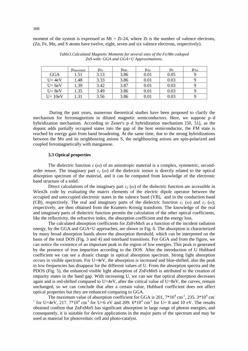
The calculated total and local magnetic moments per TM atom within the muffin-tin
spheres as well as in the interstitial sites for ZnFeMnS are given in Table 3. Due to unoccupied
TM 3d states, permanent local magnetic moments are produced in these materials. The results
show that the total magnetic moments generally come from the TM ions with a little contribution
of Zn and S sites whose magnetic moments are parallel to the TM ions. It can be seen from Fig. 05
that there is hybridization between S p states and the TM 3d states and this p–d hybridization
decreases the total magnetic moments of the TM atoms from its free space charge value and
generates a small local magnetic moments on the non-magnetic Zn and S atoms. The calculated
total magnetic moment of ZnFeMnS compound is still 9 μB, for GGA and GGA+U, and Hubbard
coefficient doesn’t affect μt; however as U increases, the interstitial magnetic moment decreases
and iron magnetic moment increases which maintains μt invariable. The calculated integer
magnetic moment of the ZnFeMnS compound, which indicates stability of half-metallic behavior,
follows the Slater-Pauling rule. According to the Slater-Pauling rule [49], the total magnetic
308
moment of the system is expressed as Mt = Zt-24, where Zt is the number of valence electrons,
(Zn, Fe, Mn, and S atoms have twelve, eight, seven and six valence electrons, respectively).
Table3.Calculated Magnetic Moments for several sites of the Fe/Mn codoped
ZnS with: GGA and GGA+U Approximations.
μinterstitial μFe μMn μZn μS μTot
GGA 1.51 3.13 3.86 0.01 0.05 9
U= 4eV 1.48 3.33 3.86 0.01 0.03 9
U= 6eV 1.39 3.42 3.87 0.01 0.03 9
U= 8eV 1.35 3.49 3.86 0.01 0.03 9
U= 10eV 1.31 3.56 3.86 0.01 0.03 9
During the past years, numerous theoretical studies have been proposed to clarify the
mechanism for ferromagnetism in diluted magnetic semiconductors. Here, we suppose p–d
hybridization mechanism. According to Zener's p–d hybridization mechanism [50, 51], as the
dopant adds partially occupied states into the gap of the host semiconductor, the FM state is
reached by energy gain from band broadening. At the same time, due to the strong hybridizations
between the Mn and its neighbouring anions S, the neighbouring anions are spin-polarized and
coupled ferromagnetically with manganese.
3.3 Optical properties
The dielectric function ε (ω) of an anisotropic material is a complex, symmetric, second-
order tensor. The imaginary part ε2 (ω) of the dielectric tensor is directly related to the optical
absorption spectrum of the material, and it can be computed from knowledge of the electronic
band structure of a solid.
Direct calculations of the imaginary part ε2 (ω) of the dielectric function are accessible in
Wien2k code by evaluating the matrix elements of the electric dipole operator between the
occupied and unoccupied electronic states in the valence band (VB), and in the conduction band
(CB), respectively. The real and imaginary parts of the dielectric function ε1 (ω) and ε2 (ω);
respectively, are then obtained from the Kramers–Kronig transform. The knowledge of the real
and imaginary parts of dielectric function permits the calculation of the other optical coefficients,
like the reflectivity, the refractive index, the absorption coefficient and the energy loss.
The calculated absorption coefficients for ZnFeMnS as a function of the incident radiation
energy, by the GGA and GGA+U approaches, are shown in Fig. 6. The absorption is characterized
by many broad absorption bands above the absorption threshold, which can be interpreted on the
basis of the total DOS (Fig. 3 and 4) and interband transitions. For GGA and from the figure, we
can notice the existence of an important peak in the region of low energies. This peak is generated
by the presence of iron impurities according to the DOS. After the introduction of U Hubbard
coefficient we can see a drastic change in optical absorption spectrum. Strong light absorption
occurs in visible spectrum. For U=4eV, the absorption is increased and blue-shifted, also the peak
in low frequencies has disappear for the different values of U. From the absorption spectra and the
PDOS (Fig. 5), the enhanced visible light absorption of ZnFeMnS is attributed to the creation of
impurity states in the band gap. With increasing U, we can see that optical absorption decreases
again and is red-shifted compared to U=4eV, after the critical value of U=8eV, the curves, remain
unchanged, so we can conclude that after a certain value, Hubbard coefficient does not affect
optical properties but they are enhanced comparing to GGA.
The maximum value of absorption coefficient for GGA is 201, 7*104 cm
-1, 235. 3*10
4 cm
-
1 for U=4eV, 217. 7*10
4 cm
-1 for U=6 eV and 209. 6*10
4 cm
-1 for U= 8 and 10 eV. The results
obtained confirm that ZnFeMnS has significant absorption in large range of photon energies, and
consequently, it is suitable for device applications in the major parts of the spectrum and may be
used as material for photovoltaic cell and photo-catalyst.

309
0 10 20 300
50
100
150
200
250
GGA
U=4eV
U=6eV
U=8eV
U=10eV
Ab
sorp
tion
Coef
fici
ent(
104 /c
m)
Energy (eV)
Fig.6.Absorption coefficient of ZnMnS and ZnFeMnS.
In Fig. 7 we plot the reflectivities of quaternary ZnFeMnS from the infrared spectral
region to the ultraviolet. We find the same trend found in the absorption. For the GGA, we see that
the reflectivity is very close to 43 % in the infrared, due to the peak caused by the absorption peak
which we have related to Fe impurities. The maximum of reflectivity occurs in the energy range 5
- 17 eV and arises from inter-band transition. For GGA+U the minimum of reflectivity occurs in
the energy range 1- 5 eV and is probably due to the collective plasma resonance. The depth of the
plasma resonance can be determined by the imaginary part of the dielectric function [52]. It is also
found that the shapes of the four curves for are very similar, and from the critical value of U=8eV,
the curves are superposed. The peaks of reflectivity curve are shifted to higher energy side
comparing to the GGA.
0 10 20 300,0
0,2
0,4
0,6
GGA
U=4eV
U=6eV
U=8eV
U=10eV
Ref
lect
ivit
y
Energy (eV)
Fig.7. Frequency dependent reflectivity of ZnFeMnS.
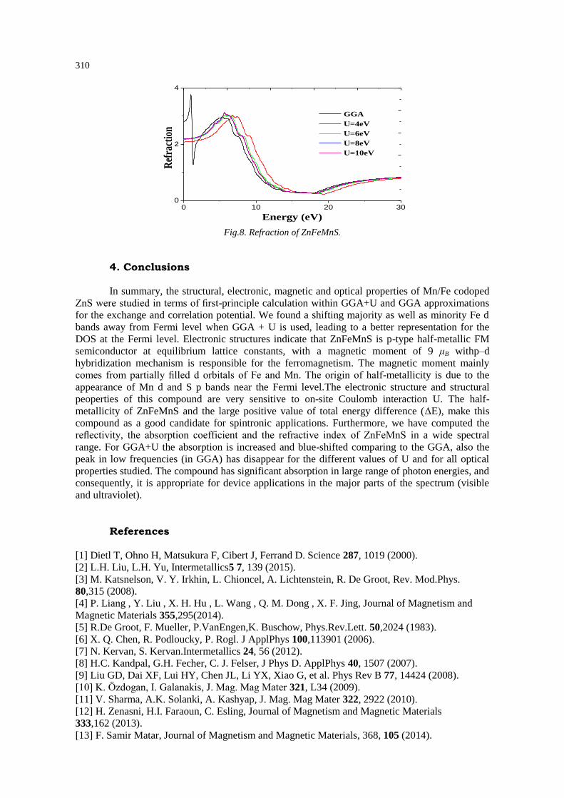
The calculated refractive index of ZnFeMnS using GGA and GGA+U is presented in Fig.
8. A broad spectrum over a wide energy and frequency is noted. We can notice the same trend as
for the other optical properties studied before. It is clear from the figure that the refractive index of
the material is blue-shifted with the increase of U coefficient. For GGA, a maximum can be
observed in the form of a bump in the spectrum at a particular energy. For GGA and GGA+U, and
at intermediate energies a few bumps appear and then the curves vanish at higher energies.
310
0 10 20 300
2
4
GGA
U=4eV
U=6eV
U=8eV
U=10eV
Ref
ract
ion
Energy (eV)
Fig.8. Refraction of ZnFeMnS.
4. Conclusions
In summary, the structural, electronic, magnetic and optical properties of Mn/Fe codoped
ZnS were studied in terms of first-principle calculation within GGA+U and GGA approximations
for the exchange and correlation potential. We found a shifting majority as well as minority Fe d
bands away from Fermi level when GGA + U is used, leading to a better representation for the
DOS at the Fermi level. Electronic structures indicate that ZnFeMnS is p-type half-metallic FM
semiconductor at equilibrium lattice constants, with a magnetic moment of 9 μB withp–d
hybridization mechanism is responsible for the ferromagnetism. The magnetic moment mainly
comes from partially filled d orbitals of Fe and Mn. The origin of half-metallicity is due to the
appearance of Mn d and S p bands near the Fermi level.The electronic structure and structural
peoperties of this compound are very sensitive to on-site Coulomb interaction U. The half-
metallicity of ZnFeMnS and the large positive value of total energy difference (ΔE), make this
compound as a good candidate for spintronic applications. Furthermore, we have computed the
reflectivity, the absorption coefficient and the refractive index of ZnFeMnS in a wide spectral
range. For GGA+U the absorption is increased and blue-shifted comparing to the GGA, also the
peak in low frequencies (in GGA) has disappear for the different values of U and for all optical
properties studied. The compound has significant absorption in large range of photon energies, and
consequently, it is appropriate for device applications in the major parts of the spectrum (visible
and ultraviolet).
References
[1] Dietl T, Ohno H, Matsukura F, Cibert J, Ferrand D. Science 287, 1019 (2000).
[2] L.H. Liu, L.H. Yu, Intermetallics5 7, 139 (2015).
[3] M. Katsnelson, V. Y. Irkhin, L. Chioncel, A. Lichtenstein, R. De Groot, Rev. Mod.Phys.
80,315 (2008).
[4] P. Liang , Y. Liu , X. H. Hu , L. Wang , Q. M. Dong , X. F. Jing, Journal of Magnetism and
Magnetic Materials 355,295(2014).
[5] R.De Groot, F. Mueller, P.VanEngen,K. Buschow, Phys.Rev.Lett. 50,2024 (1983).
[6] X. Q. Chen, R. Podloucky, P. Rogl. J ApplPhys 100,113901 (2006).
[7] N. Kervan, S. Kervan.Intermetallics 24, 56 (2012).
[8] H.C. Kandpal, G.H. Fecher, C. J. Felser, J Phys D. ApplPhys 40, 1507 (2007).
[9] Liu GD, Dai XF, Lui HY, Chen JL, Li YX, Xiao G, et al. Phys Rev B 77, 14424 (2008).
[10] K. Özdogan, I. Galanakis, J. Mag. Mag Mater 321, L34 (2009).
[11] V. Sharma, A.K. Solanki, A. Kashyap, J. Mag. Mag Mater 322, 2922 (2010).
[12] H. Zenasni, H.I. Faraoun, C. Esling, Journal of Magnetism and Magnetic Materials
333,162 (2013).
[13] F. Samir Matar, Journal of Magnetism and Magnetic Materials, 368, 105 (2014).
311
[14] A. Faisal Al-Agel, Esam Al-Arfaj, A. Ahmed Al-Ghamdi, YaroslavLosovyj, Lyudmila M.
Bronstein, Waleed E. Mahmoud, Journal of Magnetism and Magnetic Materials 360, 73 (2014).
[15] N. Hamdad, Superlattices and Microstructures76,425 (2014).
[16] A. F.Lamrani, M. Ouchri, M. Belaiche, A. El Kenz, M. Loulidi, A. Benyoussef, Thin Solid
Films, 570,45 (2014).
[17] Z. Szotek, W.M. Temmerman, A. Svane, L. Petit, G.M. Stocks, H. Winter, J Mag Mag Mater
1816,272 (2004).
[18] W. Song, J. Wang, Z. Wu, ChemPhys Lett 482, 246 (2009).
[19] S. Lv, H. Li, D. Han, Z. Wu, X. Liu , J. Meng, J. Mag. Mag. Mater 323, 416 (2011).
[20] Y. Zhang, W. Liu, H. Niu, Solid State Commun145, 590 (2008).
[21] Y. Saeed, S. Nazir, A. Shaukat, A.H. Reshak, J. Mag. Mag Mater 322, 3214 (2011).
[22] S. Kervan, N. Kervan, Journal of Magnetism and Magnetic Materials 382, 63 (2015).
[23] S. Hardev Saini, M. Singh, A.H. Reshak, K. Manish Kashyap, Journal of Magnetism and
Magnetic Materials 331,1 (2013).
[24] A. Suneela, B. Amin, A. Iftikhar, M. Maqbool, R. Ahmad, M. Haneef, N. Ikram, Current
Applied Physics 12, 184 (2012).
[25] M. El Amine Monir, H. Baltache, R. Khenata, G. Murtaza, SikanderAzam, A. Bouhemadou,
Y. Al-Douri, S. Bin Omran, R. Ali, Journal of Magnetism and Magnetic Materials 378,41 (2015).
[26] X.F. Li, J. Zhang, B. Xu, K.L. Yao, Journal of Magnetism and Magnetic Materials 324(4),
584 (2012).
[27] I. Galanakis, P. Mavropoulos, PhysRev B 67,104417 (2003).
[28] Y.Q. Xu, B.G. Liu, D.G. Pettifor, Physica B 1117, 329 (2003).
[29] K.L. Yao, G.Y. Gao, Z.L. Liu, L. Zhu, Solid State Commun133, 301 (2005).
[30] K.L. Yao, G.Y. Gao, Z.L. Liu, L. Zhu, Y.L. Li, Physica B 366, 62 (2005).
[31] X.F. Ge, Y.M. Zhang, Journal of Magnetism and Magnetic Materials 321,198 (2009).
[32] K. Deepa, K.C. Preetha, K.V. Murali, A.C. Dhanya, A.J. Ragina, T.L. Remadevi, Optik–
International Journal for Light and Electron Optics, 125(19), 5727 (2014).
[33] Z. Chen, X.X. Li, G. Du, Q. Yu, Bo. Li, X. Huang, Ceramics International 40(8), 13151
(2014).
[34] S. Zhou, Y. Li, Z. Chen, X.X. Li, N. Chen, G. Du, Ceramics International 39(6), 6763
(2013).
[35] R. Viswanath, H.S. BhojyaNaik, G.S. Yashavanth Kumar, P.N. Prashanth Kumar, K.N.
Harish, M.C. Prabhakara, Spectrochimica Acta Part A: Molecular and Biomolecular
Spectroscopy125, 222 (2014).
[36] J. Yuvaloshini, Ra. Shanmugavadivu, G. Ravi, Optik - International Journal for Light and
Electron Optics, 125(6), 1775 (2014).
[37] S. Sambasivama, D. P.Josephb, D. R.Reddya, B.K. Reddya, C.K. Jayasankara, Mater. Sci.
Eng. B 150(2), 125 (2008).
[38] S.P. Patel, J.C. Pivin, A.K. Chawla, R. Chandra, D. Kanjilal, L. Kumar, J. Magn. Magn.
Mater. 323(22), 2734 (2011).
[39] C.W. Zhang, S. S. Yan, J. Appl. Phys. 107(4), 043913 (2010).
[40] H.Y. Yan, Y.Q. Li, Y.R. Guo, Q.G. Song, Y.F. Chen, Phys. B: Condens. Matter 406(3), 545
(2011).
[41] A.J. Cohen, P. Mori-Sanchez, W. Yang, Science 321, 792 (2008).
[42] V.I. Anisimov, J. Zaanen, O.K. Andersen, Phys Rev B 44, 44943 (1991).
[43] A. Abbad, S. Bentata, H.A. Bentounes, W. Benstaali, B.Bouadjemi, Material Science in
Semiconductor Processing 16, 576 (2013).
[44] O.K. Andersen, Phys. Rev. B 12 (1975) 3060.
[45] K. Schwarz and P. Blaha Computational Materials Science 28, 259 (2003).
[46] P. Blaha, K. Schwarz, G. K. H. Madsen, D. Kvasnicka, J. Luitz, Techn. Universitat Wien,
Austria, 2001.
[47] J.P. Perdew, A. Ruzsinszky, I.G. Csonka, O.A. Vydrov, G.E. Scuseria, L.A. Constantin,
X. Zhou, K. Burke, Phys.Rev.Lett100, 136406 (2008).
[48] F.D. Murnaghan, Proc. Natl. Acad. Sci. USA 30, 5390 (1944).
[49] T. Graf, C. Felser, S.S.P. Parkin, Prog Solid State Chem 39, 391 (2011).

312
[50] H. Akai, Phys. Rev. Lett 81, 3002 (1998).
[51] K. Sato, P.H. Dederichs, H. Katayama-Yoshida, Europhys.Lett 61(3), 403 (2003).
[52] A. H. Reshak, Z. Charifi, H. Baaziz, Eur. Phys. J. B 60, 463 (2007).
Recommended