Products – 2011 1 / 57
Industrial Grade PCI DIO 96 Board
96 digital input/output lines
Support s all PPI Modes (Mode0, Mode 1 and Mode 2)
5 V TTL/CMOS
Compatible with NI DIO Card
2-wire handshaking capability
Known power-up states
Driver simplifies configuration and measurements
Operating Systems
Windows 2000/NT/XP, LabVIEW, Linux
Application
ATE
Data Acquisition System
Process Control Industries
Industrial Automation
Environmental Conditions
Operating Temperature: -40°C to +75°C
Storage Temperature: -40°C to +85°C
90% Relative Humidity (Non-condensing)

Products – 2011 2 / 57
PMC DIO Board
Features:
Bus Interface:- 32 Bit PCI Bus with PMC Interface
Speed of operation up to 66MHz
Spartan-3AN FPGA based design
128 channel digital I/O signal (64 I/O on PMC interface and 64 on Front panel interface)
Input/output ON state=3.5V to 5.0 max at -24mA
Input/output OFF state= 0.8max at 24mA
16 groups of 8 channels can be programmed as input/output
Driver interface for Windows2000/XP/VISTA and LINUX OS
Self Test future
Application
ATE
Data Acquisition System
Process Control Industries
Industrial Automation
Environmental Conditions
Operating Temperature: 0°C to 50°C
Storage Temperature: -40°C to +85°C
90% Relative Humidity (Non-condensing)

Products – 2011 3 / 57
RIO DIO AIO Board
Features:
Bus Interface:- 16 Bit Data bus, 8 Bit Address Bus
Spartan-3AN FPGA based design
Digital IO:
24 Channel digital I/O signal
Input/output ON state=3.5V to 5.0 max at -24mA
Input/output OFF state= 0.8max at 24mA
3 groups of 8 channels can be programmed as input/output
Analog Output:
24 channel single ended analog Output – (Replaceable with Analog Input Channel)
Unipolar or bipolar voltage output
Programmable output voltage: 0-5V, 0-10V, ±5V, ±10V
16 bit Resolution
Conversion time 10usec
Over current protection
Analog Input:
24 Single Ended Inputs – (Replaceable with Analog Output Channels)
Input Resolution:- 16 Bits
Input Range:- ± 10V
Sampling Rate up to 250Ks/S per channel
Application
ATE
Data Acquisition System
Process Control Industries
Industrial Automation

Products – 2011 4 / 57
PMC AO Board
Features
Bus Interface:- 32 Bit PCI Bus with PMC Interface
Speed of operation up to 66MHz
Spartan-3AN FPGA based design
32 channel single ended analog Output
Unipolar or bipolar voltage output
Programmable output voltage: 0-5V, 0-10V, 0-10.8V, ±5V, ±10V, ±10.8V and is capable of driving
up to +/-20mA
16 bit Resolution
Conversion time 10usec typ
Over current protection
Driver interface for Windows2000/XP/VISTA and LINUX OS
Self Test future
Application
ATE
Data Acquisition System
Process Control Industries
Industrial Automation
Environmental Conditions
Operating Temperature: 0°C to 50°C
Storage Temperature: -40°C to +85°C
90% Relative Humidity (Non-condensing)

Products – 2011 5 / 57
PMC High Speed Data Acquisition Board
Features
Bus Interface:- 64 Bit PCI Bus with PMC Interface
Virtex-4 FPGA based design
32 channel digital I/O signal
RS232 & RS485 Interface
32Mb Flash
2Mb Static RAM for data storage
Analog Inputs:- 2 Channel
Input Resolution:- 14 Bits
Sampling rate up to 125MSPS
Filter:- Low Pass Filter for all channels
Two Analog Outputs
14 bit Resolution
Driver interface for Windows2000/XP/VISTA and LINUX OS
Self Test future
Applications
ATE
Data Acquisition System
Process Control Industries
Industrial Automation
Environmental Conditions
Operating Temperature: 0°C to 50°C
Storage Temperature: -40°C to +85°C
90% Relative Humidity (Non-condensing)

Products – 2011 6 / 57
PMC ARINC 429 Board
Features
Bus Interface:- 32 Bit PCI Bus with PMC Interface
Speed of operation up to 66MHz
Spartan-3AN FPGA and Arinc429 controller based design
8 transmit and 8 receive independent channels
Driver interface for Windows2000/XP/VISTA and LINUX OS
Self Test future
Application
ATE
Data Acquisition System
Process Control Industries
Industrial Automation
Environmental Conditions
Operating Temperature: 0°C to 50°C
Storage Temperature: -40°C to +85°C
90% Relative Humidity (Non-condensing)

Products – 2011 7 / 57
PMC ARINC 717 Board
Features
Bus Interface:- 32 Bit PCI Bus with PMC Interface
Speed of operation up to 66MHz
Spartan-3AN FPGA with ARINC 717 IP Core
One Channel ARINC 717 Transmitter and Receiver
Generates all PCM telemetry signals like NRZ, Bi-Phase, Differential Bi-phase, DM
signals
Used to test all types of PCM based telemetry equipments
Configurable output signals format (parity, word length, Minor, Major frame, Bit
position)
User can configure the words and word positions in the frame
Driver interface for Windows2000/XP/VISTA and LINUX OS
Self Test future
Application
ATE
Data Acquisition System
Process Control Industries
Industrial Automation
Environmental Conditions
Operating Temperature: 0°C to 50°C
Storage Temperature: -40°C to +85°C
90% Relative Humidity (Non-condensing)

Products – 2011 8 / 57
PMC MIL1553B Board
Features:
Bus Interface:- 32 Bit PCI Bus with PMC Interface
Speed of operation up to 66MHz
1553B (DDC) controller based design
2 dual redundant channels
Driver interface for Windows2000/XP/VISTA and LINUX OS
Self Test future
Application
ATE
Data Acquisition System
Process Control Industries
Industrial Automation
Environmental Conditions
Operating Temperature: 0°C to 50°C
Storage Temperature: -40°C to +85°C
90% Relative Humidity (Non-condensing)

Products – 2011 9 / 57
3U CPCI MIL1553B Board
Features:
Bus Interface:- 32 Bit PCI Bus with 3 U Form factor
PCI to PCI Bridge Interface
Speed of operation up to 66MHz
1 1553B dual redundant channel
4 RS422 Channels
16 TTL I/O Channels
Message Storage Buffer
Driver interface for Windows2000/XP/VISTA and LINUX OS
Self Test future
Application
ATE
Data Acquisition System
Process Control Industries
Industrial Automation
Environmental Conditions
Operating Temperature: 0°C to 50°C
Storage Temperature: -40°C to +85°C
90% Relative Humidity (Non-condensing)

Products – 2011 10 / 57
3U CPCI ARINC 429 Board
Features:
Bus Interface:- 32 Bit PCI Bus with 3 U Form factor
PCI to PCI Bridge Interface
Speed of operation up to 66MHz
8 ARINC 429 TX and 16 ARINC 429 RX channels
4 RS422 Channels
16 TTL I/O Channels
Message Storage Buffer
Driver interface for Windows2000/XP/VISTA and LINUX OS
Self Test future
Application
ATE
Data Acquisition System
Process Control Industries
Industrial Automation
Environmental Conditions
Operating Temperature: 0°C to 50°C
Storage Temperature: -40°C to +85°C
90% Relative Humidity (Non-condensing)

Products – 2011 11 / 57
C012 Communication Board (Rear IO & M Module Interface)
Suitable for standard desktops
Four channel in single board
Up to 10 Mbits/sec operating speed
Low Cost solution
Standard INMOS link protocol
Communicates with transputers
Converts between serial link and parallel bus
Tristate bidirectional bus interface
Memory mapped registers
Interrupt capability
TTL compatibility
APPLICATIONS
Connecting microprocessors to transputers
High speed links between microprocessors
Inter-family microprocessor interfacing
Environmental Conditions
Operating Temperature: 0°C to 50°C
Storage Temperature: -40°C to +85°C
90% Relative Humidity (Non-condensing)

Products – 2011 12 / 57
One Wire Communication Board
Digital serial bus communication with low speed data over a single line, Both signaling and driving
power over a same single signal.
Protocol used in small inexpensive devices. Such as digital thermometer, weather instruments,
laptop sub module, authenticate system and some cell phone battery packs.
Always master only initiates the communication and in overall in charge of the network.
Bus communicates with master and slave at a low data rate of 12kbps.
All terminals in the network are communicating by half-duplex mode.
Maximum of 255 nodes in each 1-wire network
Each data transaction will start with 480micro second low RESET pulse.
Features of node:
Each 1-Wire slave has a unique 64-bit serial number that acts as its node address, which is
stored in its ROM the 64 bit serial number again divided in to 3 groups.
The first byte stores the 8-bit family codes that identify the device type, which can be master or
Slave.
The next six bytes store a customizable 48-bit individual address, device to be individually
selected from among many that can be connected to the same 1- wire bus.
The last byte, the most significant byte (MSB), contains a CRC of a value based on data of first
seven bytes.
All nodes will respond to a master on reception of RESET pulse.
Application
Elevators
Automobiles
Process Control Industries
Industrial Automation
Environmental Conditions
Operating Temperature: 0°C to 50°C
Storage Temperature: -40°C to +85°C
90% Relative Humidity (Non-condensing)

Products – 2011 13 / 57
PCI Carrier Board
Features
64 bit PCI edge connector
64 bit PMC connectors
Operated frequency up to 66MHz
Regulated 3.3v supply to module
Application
ATE
Data Acquisition System
Process Control Industries
Industrial Automation
Environmental Conditions
Operating Temperature: 0°C to 50°C
Storage Temperature: -40°C to +85°C
90% Relative Humidity (Non-condensing)

Products – 2011 14 / 57
Pulse Acquisition Board
Used to measure the amplitude of discrete pulses driving relay coils/motors
Programmable No. of samples acquisition with programmable trigger option
Converts sine wave to square wave for pulse measurement
Measures amplitude of sine wave
16 Bit ADC interface
16 Bit data bus host interface
FPGA based design with flexible configuration
1K FIFO Storage
Application
ATE
Data Acquisition System
Motor Control
Industrial Automation
Environmental Conditions
Operating Temperature: 0°C to +55°C
Storage Temperature: -40°C to +85°C
90% Relative Humidity (Non-condensing)

Products – 2011 15 / 57
3U and 6U CPCI CARRIER Board
Features
Bus Interface:- 32 Bit/64 bit PCI Bus with cPCI Interface
One / Two slots of 32/64 bit PMC connector interface
Speed of operation up to 66MHz
64 bit, 66MHz PCI Bridge based design
Self Test future
Application
ATE
Data Acquisition System
Process Control Industries
Industrial Automation
Environmental Conditions
Operating Temperature: 0°C to 50°C
Storage Temperature: -40°C to +85°C
90% Relative Humidity (Non-condensing)

Products – 2011 16 / 57
PCI to CPCI/PXI Extender Board
PCI to CPCI Extender card is used for extending the standard desktop PCI bus to compatible CPCI bus.
This will help to test all the CPCI and PXI cards without having a CPCI or PXI backplane. This card is very
low cost board and very use to interface with standard board. This board also facilitates to debug the
CPCI and PXI boards.
Features:
Suitable for standard desktops
No software or driver interface required
Suitable for CPCI and PXI boards
Supports 33MHZ and 66Mhz Clock
Supports 32Bit and 64Bit Bus
Low Cost solution
Enables easy debugging
Standard half size PCI form factor
Environmental Conditions
Operating Temperature: 0°C to 50°C
Storage Temperature: -40°C to +85°C
90% Relative Humidity (Non-condensing)

Products – 2011 17 / 57
PCI to PC104 Extender Board
PCI to PC104/EPIC Extender card is used for extending the standard desktop PCI bus to compatible
PC104 or EPIC bus. This will help to test all the PC104 cards through standard PC without any
embedded processors. This card is very low cost board and very use to interface with standard board.
This board also facilitates to debug the PC104 or EPIC boards.
Features:
Suitable for standard desktops
No software or driver interface required
Suitable for CPCI and PXI boards
Supports 33MHZ and 66Mhz Clock
Supports 32Bit and 64Bit Bus
Low Cost solution
Enables easy debugging
Standard half size PCI form factor
Environmental Conditions
Operating Temperature: 0°C to 50°C
Storage Temperature: -40°C to +85°C
90% Relative Humidity (Non-condensing)

Products – 2011 18 / 57
PCI to PCI Express Board
PCI to PCI Express card is used to extend PCI / PCI-X bus from one PCI system to another system over
an optical fiber medium up to 500meters or over a copper medium up to 7meters using a PCI express
interface. This card receives/transmit PCI signals from/to the Host System. These PCI signals are
converted into PCI Express using PCI / PCI-x to PCI Express cross bridge and vice versa. The PCI
Express signal is transmitted / received through the optical interface or copper interface.
Features
Bus Interface:- 32 Bit/64 bit PCI Bus
Speed of operation up to 66MHz
Converts PCI to PCI Express
Easy Plug and Play Installation
Easily fits into standard PC cases
PCI Express Specification Version 1.0 Compliant
PCI Specification Version 2.3 Compliant
OS support: Windows 2000/NT/2003/ XP/Vista/2008/Win7
SPECIFICATIONS:
Input (Board interface): PCI /PCI-X - 32 / 64 bit at 33 / 66 MHz
Output (Field interface): x1 (2.5Gbps) PCI Express Optical interface (500 meters)
x2 (5Gbps) PCI Express Optical interface (500 meters)
x4 (10Gbps) PCI Express Optical interface (500 meters) or x4 Copper interface (7 meters)
Form Factor: Short PCI Form Factor (167.64mm (W) x 106.68mm (H))
POWER REQUIREMENTS: Power consumption: 3.3V @ 3.33A (from the PCI slot)
MECHANICAL: Board Dimensions: 167.64mm (W) x 106.68mm (H)
Application
ATE
Data Acquisition System
Environmental Conditions
Operating Temperature: 0°C to 50°C
Storage Temperature: -40°C to +85°C
90% Relative Humidity (Non-condensing)

Products – 2011 19 / 57
PCI Express to CPCI Board
PCI Express to CPCI card is used to extend PCI / PCI-X bus from one PCI system to another system over
an optical fiber medium up to 500meters or over a copper medium up to 7meters using a PCI express
interface. This card receives/transmit cPCI signals from/to the Host System. These cPCI signals are
converted into PCI Express using cPCI / PCI-x to PCI Express cross bridge and vice versa. The PCI
Express signal is transmitted / received through the optical interface or copper interface.
Features
Bus Interface:- 32 Bit/64 bit PCI Bus
Speed of operation up to 66MHz
Converts PCI Express to CPCI
Easy Plug and Play Installation
Easily fits into standard CPCI / PXI chassis
PCI Express Specification Version 1.0 Compliant
PCI Specification Version 2.3 Compliant
OS support: Windows 2000/NT/2003/ XP/Vista/2008/Win7
SPECIFICATIONS:
Input (Board interface): PCI /PCI-X - 32 / 64 bit at 33 / 66 MHz
Output (Field interface): x1 (2.5Gbps) PCI Express Optical interface (500 meters)
x2 (5Gbps) PCI Express Optical interface (500 meters)
x4 (10Gbps) PCI Express Optical interface (500 meters) or x4 Copper interface (7 meters)
Form Factor: Short PCI Form Factor (167.64mm (W) x 106.68mm (H))
MECHANICAL: Board Dimensions: 160mm (W) x 100mm (H)
Application
ATE
Data Acquisition System
Environmental Conditions
Operating Temperature: 0°C to 50°C
Storage Temperature: -40°C to +85°C
90% Relative Humidity (Non-condensing)

Products – 2011 20 / 57
Dual Channel Digital Receiver Dual Channel Digital Receiver is a complete high−frequency dual−channel A/D converter capable of
sampling rates up to 210 MHz. It accepts two front panel analog inputs and delivers digital output
samples over four FPDP (Front Panel Data Port) connectors utilizing FPDP standards.
The Dual Channel Digital Receiver features two 12−bit Analog Devices AD9430 A/D Converters, and two
user−configurable Xilinx® Virtex−IV Series FPGAs. It also features a VME A64/D64 slave interface for
setting up operating modes and selectable A/D range, and optionally provides 32−bit access from the
VMEbus to the FPGAs. It is an ideal system as a high−speed data acquisition front end for real time
recording and digital signal processing systems.
Features
Two 215−MHz, 12−bit A/D converters
RF transformers supports 700 MHz input
Four FPDP front panel outputs
FIFO buffering for real−time recording
Advanced Xilinx® Virtex−IV FPGAs
Multi−board synchronization
Specifications
Front Panel Connectors
Analog Inputs: Two female SMA connectors
Sample Clock Input: One female SMA connector
Sync/Gate Bus: One 26−pin connector, with four gates, one sync, and one clock input/output
LVDS signals, plus one sync and one gate input TTL signals
FPDP Outputs: Two 80−pin FPDP connectors (A and B)
FPDP Outputs: Two 80−pin FPDP connectors(C and D)
Analog Signal Inputs
Quantity: 2 Front panel SMA connectors
Input Type: Single−ended, non−inverting
Coupling: AC
Input Impedance: 50Ω
Full Scale Input: + 8dBm (1.59 Volts p−p) or +2 dBm (0.796 Volts p−p)
Analog Input Transformers
Products – 2011 21 / 57
Quantity: 2
Type: Mini−Circuits ADT1−1WT
3 dB Passband: 400 kHz to 800 MHz (limited to 700 MHz by A/D)
Analog/Digital Converters
Quantity: 2
Device: Analog Devices AD9430
Sampling Rate: 60 MHz to 215 MHz
Resolution: 12 bits
Bandwidth: 700 MHz at full power
Coupling: Transformer coupled
Clock Source: On-board crystal oscillator or external clock
Internal Clock
Frequency: 210−MHz crystal oscillator (standard) 213.333−MHz crystal oscillator
External Clock Input
Source: Front panel SMA connector
Type: Single−ended, non−inverting, Sine Wave
Frequency: 60 MHz to 215 MHz
Impedance: 50Ω, AC coupled
Full−scale Input Voltage: 0 to +4 dBm
External Sync/Gate Inputs
LVDS Signals: Front panel LVDS Sync Bus inputs/outputs:
GATE A: 2 LVDS pins (1 differential pair)
GATE B: 2 LVDS pins (1 differential pair)
GATE C: 2 LVDS pins (1 differential pair)
GATE D: 2 LVDS pins (1 differential pair)
FPGA SYNC: 2 LVDS pins (1 differential pair)
CLK: 2 LVDS pins (1 differential pair)
TTL Signals: Front panel TTL inputs:
TTL GATE: 1 pin
TTL SYNC: 1 pin
Gate Disable: Each gate can be disabled; when disabled, FIFO writes default to enabled
Triggering: Each gate can be programmed as a trigger
Field−Programmable Gate Arrays
Quantity: Two

Products – 2011 22 / 57
Device: Xilinx Virtex−IV XC4VFX60,Xilinx Virtex−IV XC4VSX55
Programming: Factory programmed.
Memory
SDRAM
Quantity: Two, one per FPGA
Size: 256 MBytes (32M x 32) each
Note: Each FPGA bank contains four 16M x 16 chips, configured for a 32−bit wide data bus
Interface: Interfaced to FPGA
Flash
Quantity: Two, one per FPGA
Size: 16 MBytes each
Mapping: Programmable by the corresponding FPGA
Write Enable: With jumper
Additional Flash
Quantity: Two, one per FPGA
Size: 32 MBits each
Mapping: Programmable by the corresponding FPGA
Digital Outputs
Quantity: Standard: Two Front Panel Data Port (FPDP) connectors, each providing 32−bit output
Output Type: FPDP I, non−inverted configuration FPDP II, double the selected clock rate
Clock: On−board clock
FIFOs
Quantity: Four IDT72V3690 FIFOs, one for each FPDP port
Size: 32,768 x 36
Speed: FIFOs are capable of 166 MHz speed, but are run at one half of sample clock speed
VME Slave Interface
Type: Slave A.64 D64, A64/D64
Control: Operating modes, gate/trigger, FIFO reset, data packing, FPDP I or II, FPDP framing, time sync
command and status (read only)
Environmental − Commercial Applications
Operating Temperature: 0° to 50°C
Storage Temperature: −20° to 90°C
Relative Humidity: 0 to 95% non−condensing
VME Rack Exhaust Temp: 0° to 50°C
Environmental − Ruggedized Applications Cooling Method (operational): Forced Air

Products – 2011 23 / 57
PMC FPDP Board
Features
Four FPDP front panel outputs
FIFO buffering for real−time recording
FPDP Outputs: Two 80−pin FPDP connectors (A and B)
FPDP Outputs: Two 80−pin FPDP connectors(C and D)
Quantity: Standard: Two Front Panel Data Port (FPDP) connectors, each providing 32−bit output
Output Type: FPDP I, non−inverted configuration FPDP II, double the selected clock rate
Clock: On−board clock
FIFOs
Quantity: Four IDT72V3690 FIFOs, one for each FPDP port
Size: 32,768 x 36
Speed: FIFOs are capable of 166 MHz speed, but are run at one half of sample clock speed
Environmental − Commercial Applications
Operating Temperature: 0° to 50°C
Storage Temperature: −20° to 90°C
Relative Humidity: 0 to 95% non−condensing

Products – 2011 24 / 57
Advanced Programmable Mixed Data Acquisition & Control Board
Features:
32 Bit ARM9 LPC3250 Processor (256KB SRAM)
External memory (Flash – 2 MB, RAM - 512 KB, 8KB DPRAM)
10/100 MBPS Ethernet Interface
USB 2.0 Host/Device Interface
144 Digital IO Channels – (18 * 8 Configurable Ports)
64 Analog Inputs (16 Bit, 1MSPS)
16 Analog Outputs (16 Bit)
2 RS232 Serial Ports
High Speed Logic Device with 1 M bit in system flash, 54Kbit Block Ram and 11Kbit Distributed
Ram
Power, Analog and Digital signals Interface Connectors (J1, J2 and J3 - 96 Pin Euro)
Data acquisition of all analog & digital channels
External Bus through Add on module (15 bit address bus and 16 bit data bus)
Transmission of 1Kbytes at 400us through Ethernet
Power Requirements: +15V/2.5A, -15V/2.5A and +5V/6A
Board Dimension is 366.72mm x 150mm
Portable and 9U 19” chassis mountable
Board has interface connectors in rear side as well as in front side
J1, J2 and J3 96 Pin Euro connectors at rear side and Ethernet, JTAG, RS232, USB connectors at
front side
Application
ATE
Data Acquisition System
Industrial Automation
Environmental Conditions
Operating Temperature: 0°C to 50°C
Storage Temperature: -40°C to +85°C
90% Relative Humidity (Non-condensing)

Products – 2011 25 / 57
CPCI ARM Processor Board with ‘M’ Module Interface
32 Bit ARM LPC3250 Processor (256KB SRAM)
133MHz External Bus Speed and 266 MHz internal CPU Speed
32 Bit, 33MHz CPCI Bus, 6U Form Factor
External memory ( Flash – 2 MB, RAM - 512 KB, DPRAM – 128KB)
10/100 MBPS Ethernet Interface
USB 2.0 Host/Device Interface
2 RS232 Serial Ports, 4 RS422 Serial Ports
M Module Interface
6U board compatible with CPCI & PXI backplanes
High Speed Logic Device
Hot Swap Feature
Front Panel and Rear IO Interface
External Bus through Rear IO
Reception of 3Kbytes within 2ms through Ethernet
Board Dimension is 160mm x 233.35mm
Power Requirements: +3.3V, +5V and +/-12V
Board Dimension is 160mm x 233.35mm
Board has Rear IO interface
Ethernet, JTAG, RS232, USB connectors at front side
BSPs and Driver software for Windows and Linux OS
Application
ATE
Data Acquisition System
Process Control Industries
Industrial Automation
Environmental Conditions
Operating Temperature: 0°C to 50°C
Storage Temperature: -40°C to +85°C
90% Relative Humidity (Non-condensing)

Products – 2011 26 / 57
ARM LPC2364 Board
128KB On chip Flash
16*2 line LCD Module interface
Two CAN channel at 1MPBS
Ethernet interface which supports 10/100 MBPS
Full Modem RS232 interface
RS485 interface
RTC (Real Time Clock)
2048 bits serial EEPROM with data protect and sequential read.
24 ULN outputs of 12V level.
Eight 110V DC inputs interface.
Six digital inputs interface
Four on board keys interface
Power delay circuit for external use
ON board inspection circuit
Application
Elevators
Automobile
Process Control Industries
Industrial Automation
Environmental Conditions
Operating Temperature: 0°C to 50°C
Storage Temperature: -40°C to +85°C
90% Relative Humidity (Non-condensing)

Products – 2011 27 / 57
ARM LPC2468 Board
Features:
32 Bit ARM7 LPC2468 Processor (128KB SRAM, 512KB FLASH)
10/100 MBPS Ethernet Interface
USB 2.0 Host/Device Interface
2 RS232 Serial Ports
High Speed Logic Device
External Bus Interface (15 bit address bus and 16 bit data bus)
Application
ATE
Data Acquisition System
Industrial Automation
Environmental Conditions
Operating Temperature: 0°C to 50°C
Storage Temperature: -40°C to +85°C
90% Relative Humidity (Non-condensing)

Products – 2011 28 / 57
PowerPC 404 Board Specification:
Virtex 4 FPGA with Embedded PowerPC 405 (PPC405) Core
Up to 450 MHz operation
Tri-mode Ethernet Media Access Controller
A/D Converter Blocks (10-bit / 200 kilo samples per second)
Select IO Technology (Wide selections of I/O standards from 1.5V to 3.3V)
DDR2 SDRAM (256MByte)
Program Storage Flash Memory (8MByte)
Data Storage Flash Memory (8MByte)
Vertex-4 FPGA PROM (4MByte)
Features:
Ethernet Port –10/100/1000Mbps Ethernet 2 Channels
RS232/RS422 – 9 Channels
Two SPI interfaces configured in Master-mode
Synchro to Digital converter
JTAG – Flash Programming and Debugging
Applications
Embedded Applications

Products – 2011 29 / 57
SIM SWITCHER
SPECIFICATIONS ARM9 Microprocessor Based System
Contains 6 SIM card holders
SIM card holders of push to lock/unlock type
One LED indicator is placed for each SIM card to indicate the states – NO SIM,
SIM_FREE, SIM_BUSY
External power supply cord is attached to the system
Pins of the power cord is Universally usable
USB-in connectivity present to connect with PC
System has Insulated body
Stand alone application for SIM Switching
Customer application through API support
Supports all Phones and SIM systems
APPLICATIONS Automatic Phone Testing- Compatibility verification for different service provider.
Automatic Service Provider Testing –Compatibility verification for different phone types
INTERNET
Client N
Client 1
SERVER
SIM 1SIM 2
SIM 6
MOBILE PHONE 1
MOBILE PHONE 6
USB
SIM SWITCHER

Products – 2011 30 / 57
EVDO Switch
EVDO Switch will accept the data from USB modem and converts the data in to Ethernet format
and transfers to the router/PC and vice-versa
Connects USB IF wireless modems to multiple nodes (PCs)
Compatible with GSM / CDMA
No specific application software / driver. Runs with Browser
ARM9 (LPC3250 @262MHz) Core Processor based high speed device
Automatically establishes link with ISP and PC

Products – 2011 31 / 57
FM Token less Transmitter & Receiver
Transmitter and Receiver units are designed to work at 24V DC voltage (nominal) with variation between
19.2 V to 28.8V. The system is designed to work with carrier frequency 1800/2700 Hz and modulated
frequency 65Hz/85Hz. For 1800Hz Carrier Frequency RED border is used in Front Panel and for 2700Hz
Carrier Frequency BLUE border is used in Front Panel. Maximum power consumed by transmitter and
receiver are 1.2W and 8W, respectively. Sense level for receiver is less than –19 dBm and No sense level
for receiver is more than –22 dBm with 1mw (0 dBm) transmitter power. The equipment is designed to
work satisfactorily with temperature variation from 0°C to 55°C with relative humidity of 95% at 35°C.
Suitable test points are provided in the back of the equipment to monitor the necessary parameters.
Product Model:
Type Transmitter Frequency Receiver Frequency
1800 Type 1800 Hz 1800 Hz
2700 Type 2700 Hz 2700 Hz
Transmitter Specifications:
Item Rating Remarks
Transmission frequency 1800 Hz or 2700 Hz ±2%
Transmission output 1mW, 3mW, 5mW adjustable ±10 %, -5 %
Output Impedance 600 Ohm, 1120 Ohm adjustable ±10 %
Modulation System Frequency Modulation
Modulation Frequency 65 Hz or 85Hz ±1.5Hz
Power Consumption 1.2Watt or less At 24V DC
Input Power Supply 24V DC ±20 %
Shift Frequency 160Hz ±15 %

Products – 2011 32 / 57
Receiver Specification:
Item Rating Remarks
Receiving frequency 1800 Hz or 2700 Hz ±2%
Level Range 1 to 28 dB In steps of 2dB or less
Input Impedance 600 Ohm, 1120 Ohm adjustable ±10 %
Relay output voltage 24V DC or above 21V Min.
Power Consumption 8 Watt or less At 24V DC
Input Power Supply 24V DC ±20 %
Sense level for Receiving More than -19 dBm
No sense level for receiving Less than -22 dBm
Application
Railways
Environmental Conditions
Operating Temperature: -40°C to +75°C
Storage Temperature: -40°C to +85°C
90% Relative Humidity (Non-condensing)

Products – 2011 33 / 57
Transmission of Critical Happenings - “CATCH”
Features:
CATCH is a simple and reliable system and it improves loco availability/utilization
Helps to monitor loco health so as to manage maintenance and related operations
Critical data over web on real time anywhere
Trouble shooting personnel can proactively address many faults by scanning information and
can interrogate with loco, sending suitable instruction to loco pilot enroute
Train location via GPS and diagnose problems much quicker and prevent root failures
Improve asset utilization significantly
Real time SMS can be sent to the concerned people if the alarm/annunciation is not attended by
the loco pilot
The system will have its chargeable batteries and will transmit the data at the intended time even
when the loco is switched off
The integration of the system on the existing EM 2000 will be a seamless integration and simple
one, and does not require much time and cost
The proposed system will be provided with safety and protection features, so that its operation
will not affect the Loco performance in any way
This is modular and can acquire all the Four RS 232 ports and transmit the data. This also
provided with additional USB ports so that even for other than WDP4 engine, this system can be
used
LCD proactive response will be sent to loco pilot and critical error can be addressed
Isolated (protected) Keypad Simulation
Products – 2011 34 / 57
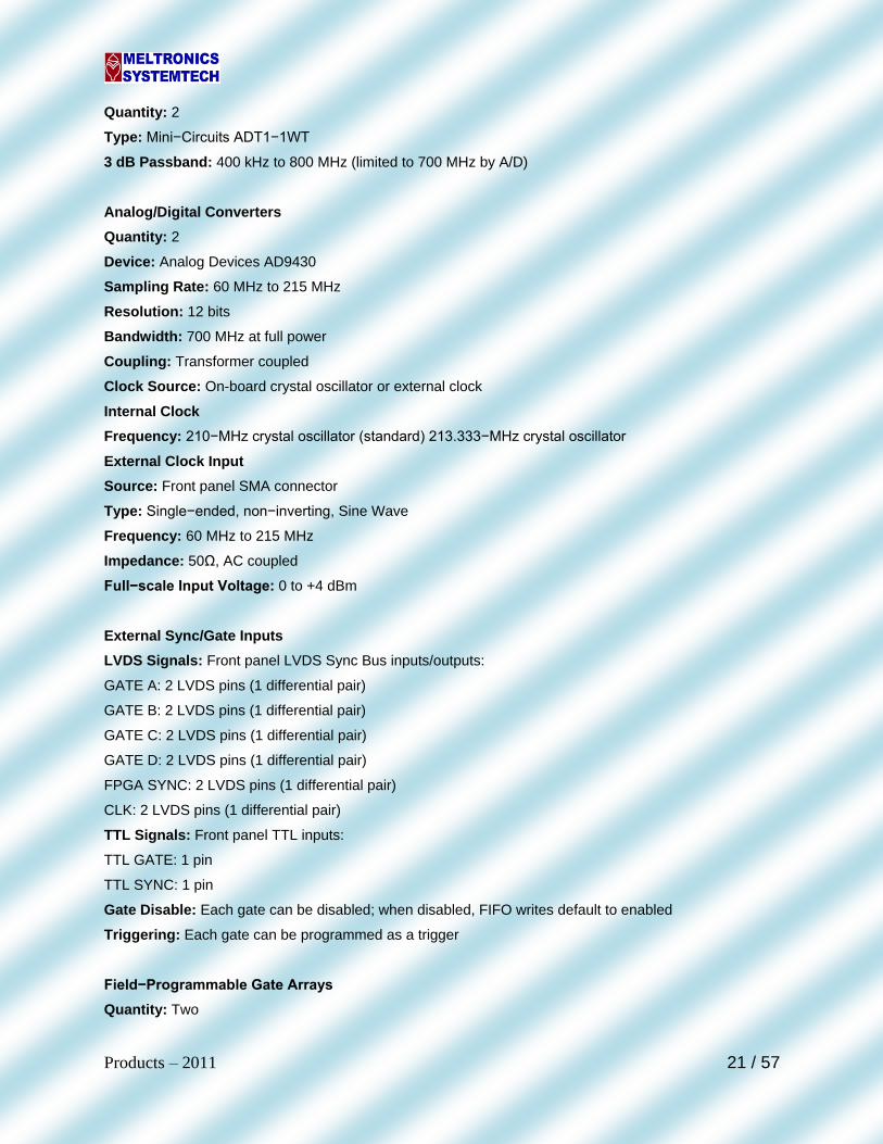
Elevator Controller System
The lift controller consists of powerful ARM LPC2364 controller chip having Enhanced Vectored Interrupt
Controller, Ethernet 10/100 MAC with DMA, USB 2.0 Full Speed Device Controller, CAN 2.0B with two
channels, General purpose DMA controller, Four UART, one with full modem interface, Three I2C serial
interfaces, Three SPI/SSP serial interfaces, I2S interface, 10-bit ADC with 6 channels, 10-bit DAC, Four
32-bit timers. The lift controller can capable latching 3 ports for Output port writing, it can read 6 Opto
input line and four internal Key inputs. Also can display all the Floor information on the 64*128 byte LCD
display module.
Also the main lift controller is communicating with other salve controller using powerful CAN channels,
which is best for its supporting distributed real-time control with a very high level of security for automotive
and industrial environments. The lift controller is used for services of general application as well as
commercial use. It supports all the functionality of Simplex as well as duplex qualities with reduced design
complexity.
FEATURES:
2 CAN channel powerful Communication interface with slaves.
Single Channel Configurable Ethernet communication for debug purpose.
Support both simplex as well as duplex terminology.
Hardware design has optimized.
4 UART channel for user communication while problem trace out.
Separate latches for both reading digital inputs and output ports.
Lift status information display on the 64*128 byte LCD display module.
Lift attends all call requests on interrupt basis so improved speed.
Power for the LPC 2364 board is drawn less power 3.3V.

Products – 2011 35 / 57
CAN BASED SYSTEM
Works with 2 wires, supplied with landing displays and communication with "CAN" processor
Provides field-proven performance, lifetime support commitment.
Remote communication with modem and suitable software enables user to download the system
history from remote location
Monitor and control elevators in real time-across campus or country.
Group Control Available up to 64floors and 6 cars.
Displays car and hall calls, waiting times and Data Log Information on a color screen.
Stores information during the working day.
Self learning call allocation, allows system to read day by day call history and respond to the
unexpected travel patterns from previous experience
CAN OR SERIAL BASED G + 64 DUPLEX & GROUP CONTROLLER:
Auto Learning for slow detection and easy commissioning.
Encoder signal for floor detection.
Detail diagnostic of individual components ensures safety and reliable operation
Attached ARD for each panel for rescue in case of power fail.
Intelligent algorithm to attend any calls within 10 seconds for standard configuration.
VIP option, Fireman switch, overload protection $ protection of all other standard interfaces
integrated.
Announciator is integrated with Gong bell.
Preferable selection of floor by user, software functional options, Delay times and important
configurations.
Error diagnosis by PC interfaces; elevator error history and services details make your
maintenance job very effective and efficient in time period.
Advantages:
One Wire Display
Floor displays and car display PCB systems in serial.
One magnet per floor and one door zone on car top for any
number of floors.
Incorporated up to G + 64, auto door with integrated ARD.
Floor displays and Car push switches through one wire interface.
Floor and car displays are 2 wired interfaced.

Products – 2011 36 / 57
CAN CONTROLLER:
The "CAN" Bus Interface for Hall Controllers and Car controller
On-board EEPROM and KEY inputs for user settings parameters
LCD Module Interface
Eight 110 VDC Opto input interface
Six inputs interface
(TINS, TUIB, TDIB, FIRE, FP, PRO-SW)
RS485 Interface and RS232 Interface (Optional)
Real time clock for Time Information
Advantages
Compact Board Size 200X230 mm
Easy to access screw terminals

Products – 2011 37 / 57
Encoder Decoder Unit for Lakshaya – II
Encoder Decoder Unit is used to interact with ground station through PCM interface.
Receives and transmits command/status information on Lakshya aircraft. Also provides real
time clock synchronization, latitude/longitude information and IRIG-B Time. System is a
digital, high speed FPGA controlled, intelligent unit to interact with various sub systems.
Features:
Virtex 4 based design
GPS Interface
PCM (QPSK) Interface
Interface with sub system: RS485
Power Supply : 28V DC
Application
UAV
ATE
Environmental Conditions
Operating Temperature: -40°C to +85°C
Storage Temperature: -40°C to +85°C
90% Relative Humidity (Non-condensing)

Products – 2011 38 / 57
ESI (Electronics Systems Integration Unit)
The ESI subsystem provides platform interfaces like Gyro and on board Radar Blanking. This unit
receives Analog and Digital GYRO inputs from ship and pre- trigger pulses from on board radars of the
ship. This unit measures and provides the ship heading data to VARUNA ESM system. It also provides
Heading, Roll and Pitch data to the ECM system. This unit also generates band wise composite ESM Rx.
Blanking gates and provides all the required interfaces to ESM receiver, ECM System and System
Controller units
Features:
One Gyro Interface through synchro or resolver (SDC):
Two SPI Interface:
Two Ethernet Ports (10/100/1000)
Nine Serial Links (RS232/422):
14 Analog Trigger Pulses:
7 TTL Trigger Pulses:
13 ESM Heading Data (Blanking):
Application
Aerospace, Ships
Data Acquisition System
Industrial Automation
Environmental Conditions
Operating Temperature: 0°C to 50°C
Storage Temperature: -40°C to +85°C
90% Relative Humidity (Non-condensing)

Products – 2011 39 / 57
Ground Test Equipment (ESI Test Jig)
This Test System designed to test the analog, discrete, Ethernet, RS232, RS422, Synchro /Resolver and
SPI Signals. It is standalone test equipment and has GUI ATP Software interface with laptop/PC through
RS232/Ethernet Interface.
Features:
o Processor: NXP LPC2468, @ 72 MHz – ARM7 Processor
On-chip Memory: 512Kbyte Flash, 98Kbyte SRAM.
o Memory: I2C EEPROM USB (16Kbyte), Flash 64Kbytes
o RS232 UART Port: One RS232 UART Port
o SPI Port: Two SPI Ports supporting slave-mode.
o Digital and Analog Outputs
o DSC Module: Digital to synchro converter
o Power: +12V, -12V, +5V, 3.3V
Application
ATE
Data Acquisition System
Process Control Industries
Industrial Automation
Environmental Conditions
Operating Temperature: 0°C to 50°C
Storage Temperature: -40°C to +85°C
90% Relative Humidity (Non-condensing)

Products – 2011 40 / 57
Infotainment
• Information, Communication, Entertainment and Commerce (ICEC) - Integrated
Solution • HDTV, Tablet PC, Camera, Set Top Box, etc. – Integrated to a limited extent
• Integrated solution for extraordinary experiences & changes
• It offers full range of e-Living solutions in smart-home, smart-community, smart connectivity, smart business and smart content
• Customers can experience & enjoy the luxuries of true e-Lifestyle • Convenience, Secure and Simple
• "Transform everyday living of extraordinary people into extraordinary living everyday."
• Well Informed, Well Connected & Well Entertained
Children Infotainment and Education E-Living for Ladies
E-Living for Gentlemen E-Living for Elders
Community Services Second Home Owner Services
Personalized Media Center PR/ PRO ASSISTANCE

Products – 2011 41 / 57
Feed Formulator
This software is developed for food manufacturing industries to optimize feed manufacturing
methods. This software optimize their animals' weight gains and maintain optimum health,
this software will gives the power to change feed formulas on a moment's notice, plus track
orders, formulas, and amounts. In Addition, software will automatically adjust ingredients to
achieve optimum costs. Software will store all information in database server. Software has
following features and also database design is compatible for any additional development
packages related to organization requirements. Software is designed on modular approach
so that the future up-gradation in case of any change requirements will have minimum
impact on the existing software
Requirements: Feed Formulation
Least-Cost Feed Formulation
Optimal ingredient allocation
Composing the best finished & complement feed, additives and premixes
Managing ingredients, nutrients, premixes and products etc.
Shall be equally useful for dairy, poultry, sheep, horses, dogs and cats etc.
Shall have power to handle unlimited number of Ingredients, Nutrients and Species.
Guarantees improved user experience and fast development of new features.
Guarantees user friendly Data Management
All functionalities shall be completely integrated and can easily be navigated.
Shall work in Linear Mode which is suitable for conventional feed formulation.
Shall have facility to Export the Report data to Excel and PDF
Shall have Parametric Analysis, Shadow Price, Marginal Price and Sensitivity analysis
Feed Formulation
The process of quantifying the amounts of feed ingredients to form a single mixture
supplies all of their nutrient requirements.
Least-Cost Feed Formulation:
Combining many feed ingredients in a certain proportion to provide the balanced
nutritional feed at the least possible cost.
This can be applied to

Products – 2011 42 / 57
Market simulations
Optimal ingredient allocation
Composing the best finished & complement feed, additives and premixes
Managing ingredients, nutrients, premixes and products etc.
Feed Formulator is an easy to use software for "Least Cost Feed Formulation“.
It is equally useful for dairy, poultry, sheep, horses, dogs and cats etc.
It has power to handle unlimited number of Ingredients, Nutrients and Species.
Guarantees improved user experience and fast development of new features.
Guarantees user friendly Data Management
All functionalities are completely integrated and can easily be navigated.
It works in Linear Mode which is suitable for conventional feed formulation.
We can Export the Report data to Excel and PDF.
Parametric Analysis, Shadow Price, Marginal Price and Sensitivity analysis are
available.

Products – 2011 43 / 57
Bill of Material & MDI
BOM (Bill of Materials) and MDI (Master Drawing Index) is client server configuration
software & it is used to assist/automate purchase and stores procedure in any organization.
Software has features like to raise materials indent, purchase order, to track purchase order
status, inward materials inspection, etc… Software will store all information in database
server. Software has following features and also database design is compatible for any
additional development packages related to organization requirements.
Features:
Vendor and supplier management
Materials Request features
Purchase Order, Enquiries, Quotations management
Comparative analysis
Budget planning with respect to project
Project and component cost calculation
Inward materials inspection management
Track status of purchase order
Provides Security to access the System
It maintains the transaction History of each item(s)
Generates the Report for Month, Year and Selected Period transaction
Provides the Option to Process BOM
Shall be compatible with Part Number System
Compatible for Windows XP, 2000, VISTA and 2003 Server

Products – 2011 44 / 57
School Note Book Management System:
School Note Book Management System is an automation tool and very useful tool for
education service providers (Notes, book and accessories shops). This software is based on
client server configuration & it is used to assist/automate purchase and stores procedure for
any class students. Software has features like to configuration for different syllabus and
different education system (like State board, CBSE, ICSE, etc…). Software will store all
information in database server. Software has following features and also database design is
compatible for any additional development packages related to organization requirements.
Features:
Easy Inventory Management & Maintenance
Configure and maintain the textbooks, notebooks and
miscellaneous items for individual classes
Sales Management
Students Management
Automated Invoice Generation
Various Report Generation and Customized Sales
Reports
Client Server Architecture enables to run in multiple
nodes
Low Cost Solution
Centralized Billing System
Flexible Configuration
Quick retrial of Bill / Invoice Number
Easy to get duplicate Bill / Invoice
One step solution to issue materials
Automatically quantity is deducted for each
Bill / Invoice

Products – 2011 45 / 57
Parent Corner
Parent Corner is a very useful tool for education service providers. It helps parents,
teachers/lectures/professors, students and institute management in interacted way. This
software is based on client server configuration & it is used to record/monitor/inform
student’s attendance, performance, extracurricular activities, interest through internet/email
to their parents. Students, Teachers and parents can provide their feedback to improve the
healthy relation and to improve the performance of student. Software will store all
information in database server. Software has following features and also database design is
compatible for any additional development packages related to organization requirements.
Features:
Attendance
Schedules
Results
Assignments
Parents Applause
Teachers Applause
Achievements
Fee Details
Teachers Details
Academic Calendar
Administration

Products – 2011 46 / 57
Students Performance Measurement System
Parent Corner is a very useful tool for education service providers. It helps parents,
teachers and students in analytical way. This software is based on client server
configuration & it is used to record/monitor/inform student’s performance and interest
through statistics. Tool measures his performance in subject wise, test wise, year wise and
represents his performance in graphical method which guides teachers and parents to take
preventive and corrective measures.
Students Management
Client Server Architecture enables to run in multiple nodes
Low Cost Solution
Ability to track & analyze the subject average by various combinations like Exam - wise & class -
wise.
Statistical reports like Student Mark Comparison.
Periodical Academic performance report
Report Generation
Single user / Multi user environment

Products – 2011 47 / 57
Drive By Wire System for BMP II Combat Vehicle
Drive by wire module is used to control and navigate a remote BMP II vehicle from a base BMP II vehicle
up to a specified speed (20KMPH) through controlling different actuators and associated electronic
control units. Using the drive by wire control system, the BMP II vehicle navigation will be controlled using
a wire (Ethernet) then it will be transformed to a wire-less (Wi-Fi) link without affecting the control system.
Motor Control Unit with Actuator:
Application
Mine Detection
Unmanned Applications
Biochemical analysis
Environmental Conditions
Operating Temperature: -20°C to +65°C
Storage Temperature: -40°C to +85°C
90% Relative Humidity (Non-condensing)

Products – 2011 48 / 57
Hybrid robot
Development of hybrid locomotion robot such as sliding by legs and crawling by tracks for antipersonnel
mine detection. Develop the hybrid locomotion robot mechanical system which consists of the locomotion
by means of legs and tracks. Control the robot motion dynamically through Ethernet wire and further
control the robot in specified path by programming the vehicle. The hybrid robot will have a manipulator
arm for carrying the antipersonnel mine detection sensor.
Application
Mine Detection
Unmanned Applications
Environmental Conditions
Operating Temperature: -20°C to +65°C
Storage Temperature: -40°C to +85°C
90% Relative Humidity (Non-condensing)

Products – 2011 49 / 57
Advanced ASCAN BIOMETER
Advanced ASCAN bio-meter is a versatile A-scan system for Biometry and IOL Power
Computation. This system is used for finding eye axial length; cornea thickness and
calculating the eye IOL power value. This system has capability of storing 1000 patient
records and downloading facility. System will work as an ASCAN BIOMETER or ASCAN /
PACHYMETER BIOMETER system. System consists of touch screen, color LCD, USB interface
for downloading and thermal printer interface. It is an ARM9 micro controller-based system.
This system uses ultrasound signal for measurements
Features:
Probe: A-scan solid tip probe is built to last for years. Frequency -10 MHz, built in Fixation LED with
flexible cable.
Display: Large 800x600 Pixel color display with Back light.
Measurement: Axial Length Measurement range from 15mm to 38mm.Simultaneously shows the axial
length, anterior chamber depth, lens thickness, and A-scan waveforms in real-time
Measurement Accuracy: + or - 0.1mm., Resolution : 0.01mm. Measurement: Auto / Manual. An audible
signal to the Operator indicates a valid measurement has been completed and stored in memory. Cursor
to measure the user desired waveform positions.
IOL Power Calculation Formulas: SRK T, SRK II, Binkhorst I, Holladay and Hoffer Q, AME
Printer: High speed Thermal printer.
USB Host Interface
Electrical Requirements: 230 V AC/ 50 Hz

Products – 2011 50 / 57
System on Module (ARM 9 SOM)
Features:
Processor: LPC3250 processor with ARM 9 core running at 266 MHz
SDRAM Memory: DDR2 256 MB (scalable to 512 MB)
Flash Memory: NAND flash 512 MB
Display & Graphics: Programmable color LCD controller supports up to a TFT interface
Touch screen: Integrated touch screen controller
Network Support: 10/100 Base-T Ethernet PHY
PC Interface: One USB 2.0 high-speed On-the-Go interface
Serial Interfaces: Up to four external UARTs
+ CAN 2.0B controller
+ Three I2C ports
+ Three SPI ports
GPIO: Programmable I/O depending on peripheral requirements
Mechanical: 60 mm wide x 60 mm long x 5.4 mm high
Application
ATE
Data Acquisition System
Process Control Industries
Industrial Automation
Environmental Conditions
Operating Temperature: 0°C to 50°C
Storage Temperature: -40°C to +85°C
90% Relative Humidity (Non-condensing)

Products – 2011 51 / 57
Signal Processor Board
Features:
Frequency coverage from 5 kHz to 30 MHz in 1-Hz steps
High dynamic range: +30 dBm 3rd-order intercept typical
Digital filtering provides 58 IFBWs from 56 Hz to 8.0 kHz with exceptional shape factors
AM, Synchronous AM, FM, CW, USB, LSB & ISB detection modes standard
Tunable notch filter
Fast, flexible scanning with 100 memory channels
Large readable LED displays & user-friendly controls
Noise blanking & pass band tuning
Internal switchable preamplifier & attenuator
Operator-selectable RS-232, RS-485, or
RS-422 remote control
Viretx 5 FPGA based design (Two virtex for image processing)
LPC2468 ARM 7 Processor based design
MIL1553B and RS485 Interface
Two High speed 14 bit ADC (125MSPS) for I & Q
Sampling
Direct sampling 2-30MHz
Audio CODEC
Conduction Cooled Board
Application
Digital Receivers
Communication Systems
RADAR
Environmental Conditions
Operating Temperature: -40°C to +85°C
Storage Temperature: -40°C to +85°C
90% Relative Humidity (Non-condensing)

Products – 2011 52 / 57
Motor Control (Motor Driver) Unit:
The MCU system is designed based on ARM 7 core LPC2917 Microcontrollers to drive two DC servo
motors (BLDC) independently. The unit consists of two LPC2917 micro controllers and each controlling
one motor. The each controller having two CAN Bus interface with for remote communication. The unit is
enclosed with rugged chassis with circular connector for CAN Bus communication and other interfaces.
The Motor Control Unit is controlled through CAN Bus. It receives command and generates PWM Outputs
to drive the motor. PWM is used to switch the motor voltage depends on the pulse width.
Supply voltage 24–48 V DC for operation at safety extra-low voltage level
CAN open inside with Position, Velocity and Homing modes and scaling of units by Factor Group
Resolver, Encoder and LVDT/RVDT feedback interface
Evaluation of encoders for precision positioning operations with backlash mechanism
Evaluation of multi-turn encoders for positioning operations without referencing
Sequenced driving set positioning with sequential job logic
Online position profile generator for real-time position profile generation with 250 µs fine
interpolation
PID runs on RTOS
Applications: This MCU controls a variety of low power, low voltage brushless (BLDC) motors. It can be
used in applications, such as:
Transportation power plants
Mobile equipment (off-highway)
Material handling equipment, electric vehicles
Industrial automation
Robotics
Environmental Conditions
Operating Temperature: -40°C to +85°C
Storage Temperature: -40°C to +85°C
90% Relative Humidity (Non-condensing)

Products – 2011 53 / 57
Universal Pylon Tester
A portable test equipment to check the electrical functionalities of pylons by simulating
various store types in aircraft. This system is able to simulate the functionalities of
different PIBs (IB/MB/CF, OB & Laser). The system provides facility to test two Pylons
in parallel. The tester provides aircraft specific AC &DC voltages and facility to inject
discrete inputs for checking output(s) viz firing voltages, fusing voltages. The system
provides four channels of RS422 and Two channels of 1553B communication. Portable
unit with caster wheels with all required hardware, power supplies, instruments,
connectors and laptop housed in it.

Products – 2011 54 / 57
EVISION (Obstacle Detector)
1. Android based Multifunctional AID application for visually impaired
2. Simplifies reading/writing
3. Simplifies location of public utilities
4. Simplifies mobile phone operations
5. E-notepad to take notes electronically
6. E-book to download soft copies of books from computer or from similar devices
7. Voice recorder to record speeches
8. Read normal books through optical character recognition system
9. Read Braille text written on plain paper
10. Computer data entry keyboard and screen reader
11. Locator to locate the device if misplaced
12. Personnel locater to locate friends in a crowded gathering
13. RFID based location of personal belongings / Designated places
14. Obstacle Warning System for alerting any obstacle while walking
Obstacle Detector is a distance-measuring system based on ultrasonic sound utilizing the
LPC2364FBD100. The system transmits a burst of ultrasonic sound waves towards the subject and then
receives the corresponding echo. The LPC2364FBD100 integrated analog comparator is used to detect
the arrival of the echo to the system. The time taken for the ultrasonic burst to travel the distance from the
system to the subject and back to the system is accurately measured by the LPC2364FBD100. Assuming
the speed of sound in air at room temperature to be 1100 ft/s, the LPC2364FBD100 computes the
distance between the system and the subject and gives the information to buzzer. The minimum distance
that this system can measure is eight inches and is limited by the transmitter’s transducer settling-time.
The maximum distance that can be measured is 2 meter. The amplitude of the echo depends on the
reflecting material, shape, and size. Sound-absorbing targets such as carpets and reflecting surfaces less
than two square feet in area reflect poorly. The maximum measurable range is lower for such subjects. If
the amplitude of the echo received by the system is so low that it is not detectable by the Comparator.
This system is mainly used to replace normal sticks for the visually impaired (blind) peoples. This unit has
standard USB 2.0 for mobile interface and has android application for user interface

Products – 2011 55 / 57
Airborne Video Delay Board
Features:
Spartan FPGA based Design
Customized design for delaying & switching video inputs to RF section
Interface with EW Signal Processor Unit
Two channel video inputs and control
Video Signal Delay from 1ns to 1ms
Over duty Indications
Inhibit Control
Discrete Interface
Application:
RADARS
Electronics Warfare Systems
Automatic Test Equipments
Environmental Conditions
Operating Temperature: -40°C to +85°C
Storage Temperature: -40°C to +85°C
90% Relative Humidity (Non-condensing)

Products – 2011 56 / 57
Ruggedized CPCI Processor Board Specifications:
Processor:
Pentium 1GHZ / PowerPC MPC8640 (1Ghz)
Memory
SDRAM (1024 MB)
FLASH PROM (8 GBMB)
Other Interface:
Audio Output
Virtex-4 FPGA for Reconfigurable I/O Capability
Communication Interface:
Ethernet Port – 2 Channel (1GBPS)
MIL1553B – 2 Channel (Dual redundancy)
USB – 2
RS232 – 4 Channels
RS422 – 4 Channels
JTAG – Flash Programming and Debugging
Specifications
Power Supply Input: 5V DC 40A
Operating Temperature: -40°C to 85°C
Storage Temperature: -50°C to +100°C
90% Relative Humidity (Non-condensing)
Application
Airborne
ATE
Data Acquisition System
Process Control Industries
Industrial Automation

Products – 2011 57 / 57
Instrumentation (Tacho) Amplifier
Instrumentation Amplifier is a customized unit to incorporate additional line filtering and spike suppression
so that the amplifiers can operate directly off the main aircraft 28 volt system and amplifies the input
signal according dynamic input configuration. This unit is capable of working without damage in both
under and over voltage conditions. Designed for general aircraft applications
Modular design
Complete electrical isolation
1 Watt to 20 Watt output
Form Factor: Stand Alone
Application
Avionics
Aerospace
ATE
Data Acquisition System
Recommended