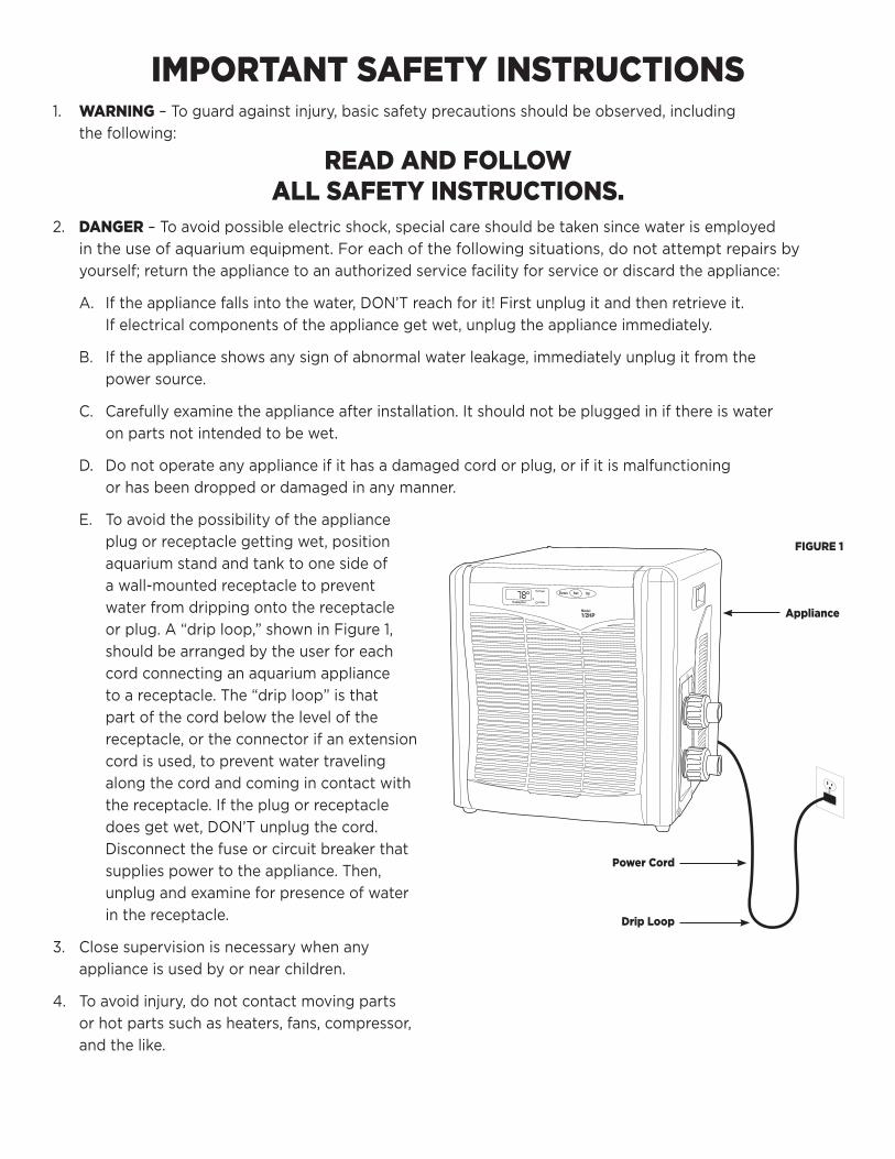
FIGURE 1
Appliance
Power Cord
Drip Loop
IMPORTANT SAFETY INSTRUCTIONS1. WARNING–Toguardagainstinjury,basicsafetyprecautionsshouldbeobserved,including
thefollowing:
READ AND FOLLOW ALL SAFETY INSTRUCTIONS.
2. DANGER–Toavoidpossibleelectricshock,specialcareshouldbetakensincewaterisemployed
intheuseofaquariumequipment.Foreachofthefollowingsituations,donotattemptrepairsby
yourself;returntheappliancetoanauthorizedservicefacilityforserviceordiscardtheappliance:
A. Iftheappliancefallsintothewater,DON’Treachforit!Firstunplugitandthenretrieveit.
Ifelectricalcomponentsoftheappliancegetwet,unplugtheapplianceimmediately.
B. Iftheapplianceshowsanysignofabnormalwaterleakage,immediatelyunplugitfromthe
powersource.
C. Carefullyexaminetheapplianceafterinstallation.Itshouldnotbepluggedinifthereiswater
onpartsnotintendedtobewet.
D. Donotoperateanyapplianceifithasadamagedcordorplug,orifitismalfunctioning
orhasbeendroppedordamagedinanymanner.
E. Toavoidthepossibilityoftheappliance
plugorreceptaclegettingwet,position
aquariumstandandtanktoonesideof
awall-mountedreceptacletoprevent
waterfromdrippingontothereceptacle
orplug.A“driploop,”showninFigure1,
shouldbearrangedbytheuserforeach
cordconnectinganaquariumappliance
toareceptacle.The“driploop”isthat
partofthecordbelowthelevelofthe
receptacle,ortheconnectorifanextension
cordisused,topreventwatertraveling
alongthecordandcomingincontactwith
thereceptacle.Iftheplugorreceptacle
doesgetwet,DON’Tunplugthecord.
Disconnectthefuseorcircuitbreakerthat
suppliespowertotheappliance.Then,
unplugandexamineforpresenceofwater
inthereceptacle.
3. Closesupervisionisnecessarywhenany
applianceisusedbyornearchildren.
4. Toavoidinjury,donotcontactmovingparts
orhotpartssuchasheaters,fans,compressor,
andthelike.
5. Alwaysunpluganappliancefromanoutletwhennotinuse,beforeputtingonortakingoffparts,
andbeforecleaning.Neveryankcordtopullplugfromoutlet.Grasptheplugandpulltodisconnect.
6. Donotuseanapplianceforotherthanintendeduse.Theuseofattachmentsnotrecommendedorsold
bytheappliancemanufacturermaycauseanunsafecondition.
7. Donotinstallorstoretheappliancewhereitwillbeexposedtotheweatherortotemperatures
belowfreezing.
8. Readandobservealltheimportantnoticesontheappliance.
9. Ifanextensioncordisnecessary,acordwithaproperratingshouldbeused.Acordratedforless
amperesorwattsthantheapplianceratingmayoverheat.Careshouldbetakentoarrangethecord
sothatitwillnotbetrippedoverorpulled.
10. Foraddedsafety,thefixturemustbepluggedintoareceptaclecontrolledbyaGFI(groundfault
interrupter)circuitbreaker.Devicemustbeproperlyconnectedtoagroundedthree-prongreceptacle.
11. Donotusethisapplianceinsuchawaythattheventsarerestrictedorblocked.Theseventsare
necessarytoavoidover-heatingandinsuresafeoperatingtemperature.
12. ThisapplianceisintendedFORHOUSEHOLDUSEONLY.
SAVE THESE INSTRUCTIONS!IMPORTANT SAFETY INFORMATION:Pleasereadthefollowingprecautionsbeforeuse!
1. Toreducetheriskofelectricshock,alwaysunplugthepumpandpowercordsbeforeperformingany
maintenance.Donotsubmersechiller.
2. Neverallowsmallchildrentotouch,climb-on,orplaywiththechiller.Adultsupervisionisrequired.
3. Neversetachilleronanunsturdyorunsupportedstructure,suchasthosewhichareunabletosupport
theweightofafilledchiller,aresuspended,canrockorsway,cansag,oronwheelsorallowsthechillerto
over-hang.Thesecouldcausethechillertoleak,crack,orevenfalloverifatopheavysituationiscreated.
4. Donotallowchillertooperatedryatanytime.
5. Alwaysobservepropermaintenancetoensureoptimaloperation.
HANDLE WITH CARE!Alwayshandlechillerwithcaretoavoidpersonalinjury.
1. Alwaysliftthechillerbythehandles.
2 Neverliftachillerwithwethands.
3 Chillersareheavyitemsandassistancemayberequiredtoliftthem.
CHILLER LOCATION
1. Forbestresults,placethechillerinalocationbestsuitedtosupportthetotalweightofthechiller.
2 Alwaysplacethechillerinaflatandlevelarea.
3. Keepchillerinawellventilatedareaandawayfromaheatingorcoolingvent.
4. Donotplacenearelectroniccomponentsandsystems(i.e.T.V,Stereosystems,etc...).
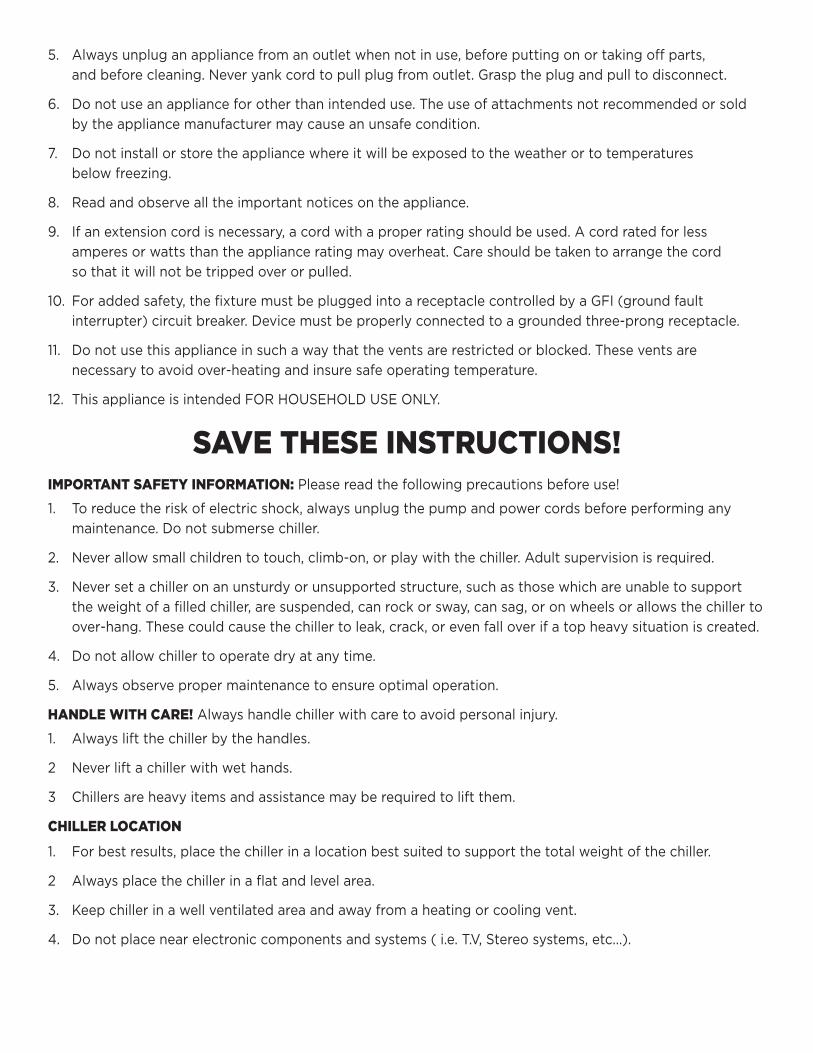
Rubber Compression Gasket (4)
Control Panel
Front Grill
Hose-Tubing Connector Elbow (2)
Compression Gasket Cap (2)
Metal HoseClamp (2)
FIGURE 2
This configuration used on 1/2 HP and 1 HP Aquarium Chillers
Outlet configuration used on 1/10 HP, 1/6 HP and 1/4 HP Aquarium Chillers
This configuration used on 1/10 HP, 1/6 HP and 1/4 HP Aquarium Chillers
Model 1/10 HP Aquarium Chiller 1/6 HP Aquarium Chiller 1/4 HP Aquarium Chiller 1/2 HP Aquarium Chiller 1 HP Aquarium Chiller
Recommended Size* Upto55gallonaquarium Upto90gallonaquarium Upto125gallonaquarium Upto250gallonaquarium Upto400gallonaquarium
Rated Voltage AC120V AC120V AC120V AC120V AC120V
Rated Cycle 60Hz 60Hz 60Hz 60Hz 60Hz
Fuse Size 10amp 15amp 15amp n/a n/a
Rated Power 1/10HP 1/6HP 1/4HP 1/2HP 1HP
Temperature Range 39°F-90°F 39°F-90°F 39°F-90°F 39°F-90°F 39°F-90°F
Temperature Deferential +/–2° +/–2° +/–2° +/–2° +/–2°
Preset Temperature 76°F 76°F 76°F 76°F 76°F
Refrigerant R134A R134A R134A R410A R410A
Recommended Flow Rate 200gph-300gph 325gph-550gph 475gph-800gph 750gph-1,500gph 1,000gph-2,000gph
Tubing Size Connectors** 5/8"or3/4"I.D.flexibletubing 5/8"or3/4"I.D.flexibletubing 5/8"or3/4"I.D.flexibletubing 3/4"or1"I.D.flexibletubing 3/4"or1"I.D.flexibletubing
** Basedona15°temperaturepulldownfromambientairtemperature.** Tubingnotincluded.
PARTS DIAGRAM
PRODUCT SPECIFICATIONS
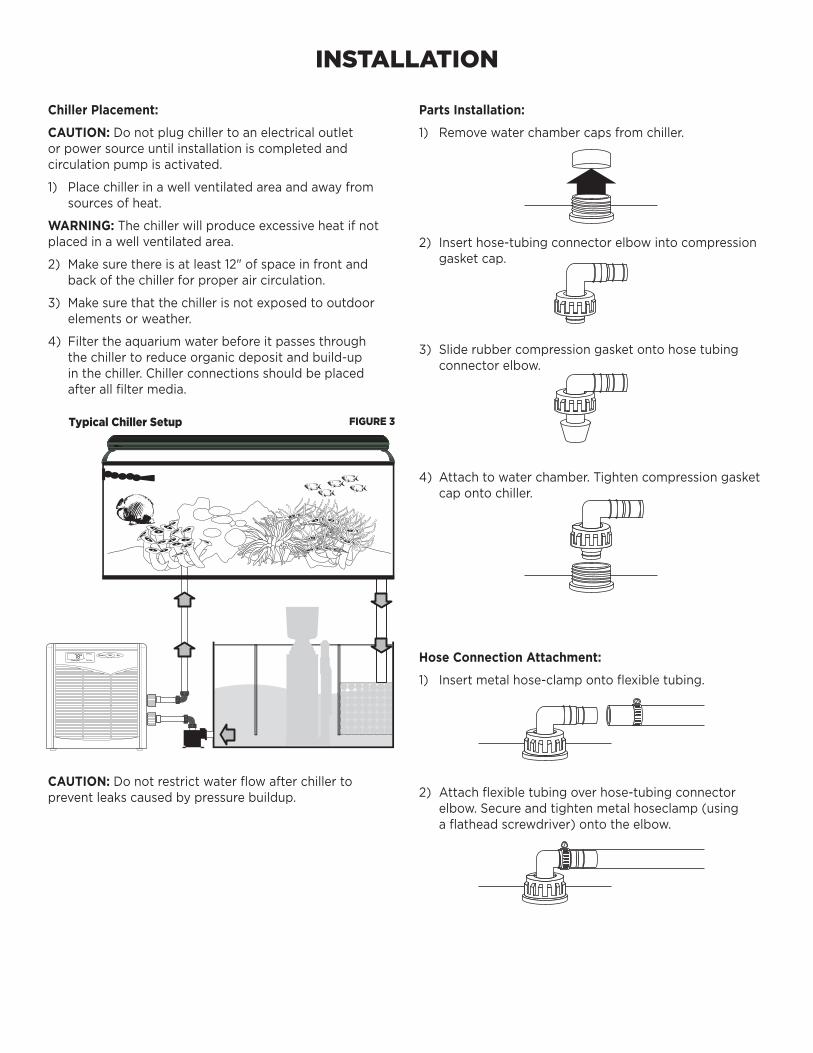
FIGURE 3Typical Chiller Setup
INSTALLATION
Chiller Placement:
CAUTION:Donotplugchillertoanelectricaloutletorpowersourceuntilinstallationiscompletedandcirculationpumpisactivated.
1) Placechillerinawellventilatedareaandawayfromsourcesofheat.
WARNING:Thechillerwillproduceexcessiveheatifnotplacedinawellventilatedarea.
2) Makesurethereisatleast12"ofspaceinfrontandbackofthechillerforproperaircirculation.
3) Makesurethatthechillerisnotexposedtooutdoorelementsorweather.
4) Filtertheaquariumwaterbeforeitpassesthroughthechillertoreduceorganicdepositandbuild-upinthechiller.Chillerconnectionsshouldbeplacedafterallfiltermedia.
CAUTION:Donotrestrictwaterflowafterchillertopreventleakscausedbypressurebuildup.
Parts Installation:
1) Removewaterchambercapsfromchiller.
2) Inserthose-tubingconnectorelbowintocompressiongasketcap.
3) Sliderubbercompressiongasketontohosetubingconnectorelbow.
4) Attachtowaterchamber.Tightencompressiongasketcapontochiller.
Hose Connection Attachment:
1) Insertmetalhose-clampontoflexibletubing.
2) Attachflexibletubingoverhose-tubingconnectorelbow.Secureandtightenmetalhoseclamp(usingaflatheadscrewdriver)ontotheelbow.
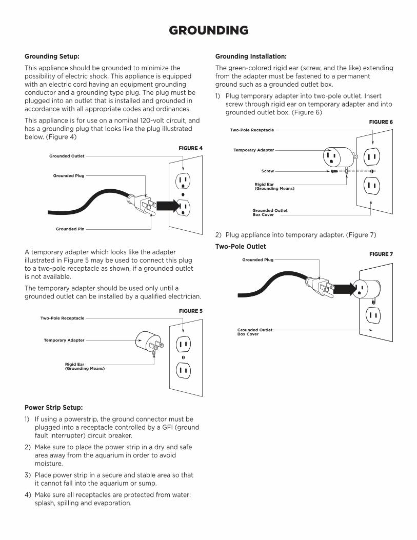
FIGURE 4
FIGURE 6
FIGURE 7
FIGURE 5
2) Plugapplianceintotemporaryadapter.(Figure7)
Two-Pole Outlet
Grounded OutletBox Cover
GROUNDING
Grounding Setup:
Thisapplianceshouldbegroundedtominimizethepossibilityofelectricshock.Thisapplianceisequippedwithanelectriccordhavinganequipmentgroundingconductorandagroundingtypeplug.Theplugmustbepluggedintoanoutletthatisinstalledandgroundedinaccordancewithallappropriatecodesandordinances.
Thisapplianceisforuseonanominal120-voltcircuit,andhasagroundingplugthatlooksliketheplugillustratedbelow.(Figure4)
Grounding Installation:
Thegreen-coloredrigidear(screw,andthelike)extendingfromtheadaptermustbefastenedtoapermanentgroundsuchasagroundedoutletbox.
1) Plugtemporaryadapterintotwo-poleoutlet.Insertscrewthroughrigidearontemporaryadapterandintogroundedoutletbox.(Figure6)
AtemporaryadapterwhichlooksliketheadapterillustratedinFigure5maybeusedtoconnectthisplugtoatwo-polereceptacleasshown,ifagroundedoutletisnotavailable.
Thetemporaryadaptershouldbeusedonlyuntilagroundedoutletcanbeinstalledbyaqualifiedelectrician.
Power Strip Setup:
1) Ifusingapowerstrip,thegroundconnectormustbepluggedintoareceptaclecontrolledbyaGFI(groundfaultinterrupter)circuitbreaker.
2) Makesuretoplacethepowerstripinadryandsafeareaawayfromtheaquariuminordertoavoidmoisture.
3) Placepowerstripinasecureandstableareasothatitcannotfallintotheaquariumorsump.
4) Makesureallreceptaclesareprotectedfromwater:splash,spillingandevaporation.
Grounded Outlet
Two-Pole Receptacle
Two-Pole Receptacle
Rigid Ear(Grounding Means)
Rigid Ear(Grounding Means)
Grounded OutletBox Cover
Temporary Adapter
Temporary Adapter
ScrewGrounded Plug
Grounded Plug
Grounded Pin
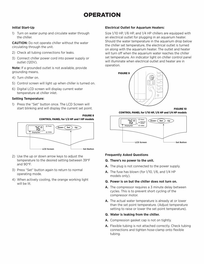
FIGURE 9
FIGURE 8CONTROL PANEL for 1/2 HP and 1 HP models
FIGURE 10CONTROL PANEL for 1/10 HP, 1/6 HP and 1/4 HP models
Set ButtonLCD Screen
Set ButtonLCD Screen
OPERATION
Initial Start-Up
1) Turnonwaterpumpandcirculatewaterthroughthechiller.
CAUTION:Donotoperatechillerwithoutthewatercirculatingthroughtheunit.
2) Checkalltubingconnectionsforleaks.
3) Connectchillerpowercordintopowersupplyoroutlet(120V).
Note:Ifagroundedoutletisnotavailable,providegroundingmeans.
4) Turnchilleron.
5) Controlscreenwilllightupwhenchilleristurnedon.
6) DigitalLCDscreenwilldisplaycurrentwatertemperatureatchillerinlet.
Setting Temperature:
1) Pressthe“Set”buttononce.TheLCDScreenwillstartblinkingandwilldisplaythecurrentsetpoint.
2) Usetheupordownarrowkeystoadjustthetemperaturetothedesiredsettingbetween39°Fand90°F.
3) Press“Set”buttonagaintoreturntonormaloperatingmode.
4) Whenactivelycooling,theorangeworkinglightwillbelit.
Frequently Asked Questions
Q. There’s no power to the unit.
A. Theplugisnotconnectedtothepowersupply.
A. Thefusehasblown(for1/10,1/6,and1/4HPmodelsonly).
Q. Power is on but the chiller does not turn on.
A. Thecompressorrequiresa3minutedelaybetweencycles.Thisistopreventshortcyclingofthecompressormotor.
A. Theactualwatertemperatureisalreadyatorlowerthanthesetpointtemperature.(Adjusttemperaturesettingtoraiseorlowerthesetpointtemperature).
Q. Water is leaking from the chiller.
A. Compressiongasketcapisnotontightly.
A. Flexibletubingisnotattachedcorrectly.Checktubingconnectionsandtightenhose-clampontoflexibletubing.
Electrical Outlet for Aquarium Heaters:
Size1/10HP,1/6HP,and1/4HPchillersareequippedwithanelectricaloutletforplugginginanaquariumheater.Shouldthewatertemperatureintheaquariumdropbelowthechillersettemperature,theelectricaloutletisturnedonalongwiththeaquariumheater.Theoutletandheaterwillturnoffwhentheaquariumwaterreachesthechillersettemperature.Anindicatorlightonchillercontrolpanelwillilluminatewhenelectricaloutletandheaterareinoperation.
MAINTENANCE
Note:Chillerhasnouserserviceableparts.
SAFETY:Alwaysunplugchillerfrompowersupplybeforeshuttingofftheflowofwater.
Monthly:
1) Checkwaterpumpandfiltersupplyingwatertochillertoensureproperwaterflow.
2) Cleanfrontgrillwithavacuumcleanertosuctionoffdustanddebris.
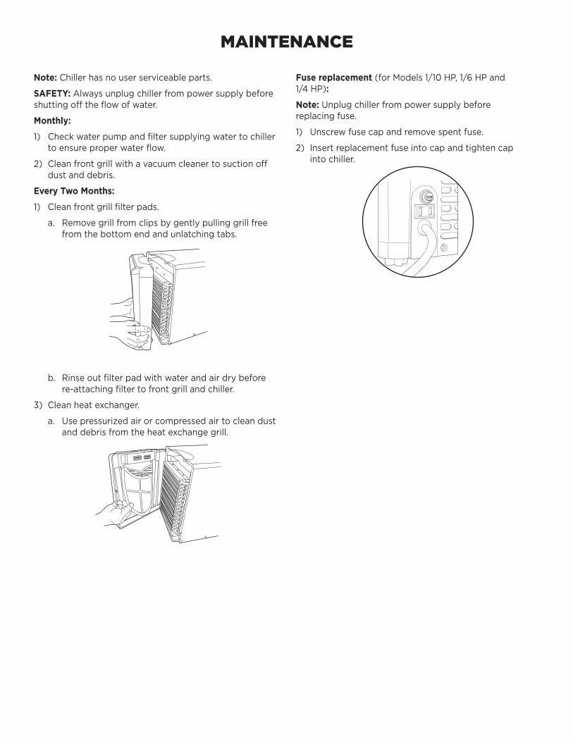
Every Two Months:
1) Cleanfrontgrillfilterpads.
a. Removegrillfromclipsbygentlypullinggrillfreefromthebottomendandunlatchingtabs.
b. Rinseoutfilterpadwithwaterandairdrybeforere-attachingfiltertofrontgrillandchiller.
3) Cleanheatexchanger.
a. Usepressurizedairorcompressedairtocleandustanddebrisfromtheheatexchangegrill.
Fuse replacement (forModels1/10HP,1/6HPand1/4HP):
Note:Unplugchillerfrompowersupplybeforereplacingfuse.
1) Unscrewfusecapandremovespentfuse.
2) Insertreplacementfuseintocapandtightencapintochiller.
WARRANTY
Coralifewarrantsthatthisproductshallbefreefromdefectiveelectricalcomponentsduetodefectsinmaterialsorworkmanshipforaperiodoftwelvemonthsfromthedateofpurchase.Ifadefectisshown,Coralifewill,atCoralife’ssolediscretion,eitherrepairorreplacetheproductwithoutcharge.Nocashrefundswillbemade.Thiswarrantyisprovidedsolelytotheoriginalconsumerpurchaseroftheproductandmaynotbetransferredorassigned.
Thiswarrantydoesnotapplytodamageresultingfromaccident,misuse,abuse,lackofreasonablecare,failuretofollowsafetyandinstallationinstructions,useoftheproductwithnon-standardelectricalservice,oranyotherdefectnotresultingfromdefectsintheelectricalcomponentsoftheproductordefectsinmaterialsorworkmanship.ThiswarrantywillnotbeeffectiveunlessanduntiltheCoralifeproductisshowntohavebeenusedinaccordancewiththesafetyandinstallationinstructionsaccompanyingtheproduct.
THISCONSTITUTESCORALIFE’SENTIREWARRANTYANDCORALIFEMAKESNOOTHERWARRANTIES,WHETHEREXPRESSORIMPLIED,WITHRESPECTTOTHEPRODUCT.CORALIFESPECIFICALLYDISCLAIMSANYANDALLIMPLIEDWARRANTIES,INCLUDING,WITHOUTLIMITATION,WARRANTIESOFMERCHANTABILITYANDFITNESSFORAPARTICULARPURPOSE.IFCORALIFECANNOTLAWFULLYDISCLAIMIMPLIEDWARRANTIESUNDERTHISLIMITEDWARRANTY,ALLSUCHWARRANTIES,INCLUDINGWARRANTIESOFMERCHANTABILITYANDFITNESSFORAPARTICULARPURPOSEARELIMITEDINDURATIONTOTHEDURATIONOFTHISWARRANTY.
CORALIFEISNOTRESPONSIBLEFORDIRECT,SPECIAL,INCIDENTALORCONSEQUENTIALDAMAGESRESULTINGFROMANYBREACHOFWARRANTYORCONDITION,ORUNDERANYOTHERLEGALTHEORY.CORALIFEEXPRESSLYDISCLAIMSALLALLEGEDDAMAGESFORLOSSOFAQUATICLIFE,PERSONALINJURY,AND/ORPROPERTYDAMAGE.Somestatesandprovincesdonotallowtheexclusionorlimitationofincidentalorconsequentialdamagesorexclusionsorlimitationsonthedurationofimpliedwarrantiesorconditions,sotheabovelimitationsorexclusionsmaynotapplytoyou.Thiswarrantygivesyouspecificlegalrights,andyoumayalsohaveotherrightsthatvarybystateorprovince.
CoralifeshallnothaveanyobligationsunderthiswarrantyunlesstheownernotifiesCoralifeinwritingofanyallegeddefect(s)within30daysofdiscoveryofthedefect(s).AnynoticetoCoralifemustbedeliveredbyUnitedStatesorelectronicmailtooneofthefollowingaddresses:
U.S.Mail:
CentralAquatics-Coralife5401WestOakwoodParkDriveFranklin,Wisconsin53132
ElectronicMail:[email protected]
CoralifeshallbeallowedareasonableperiodoftimetoinvestigateanywarrantyclaimandtoperformanytestingCoralifedeemsnecessarytodeterminethecauseofthedefect.ThiswarrantyshallbeinterpretedunderthelawsofthestateofWisconsin.
Foradditionalinformationregardingthislimitedwarranty,pleasecontactusattheaddressesabove,orcallusat888-255-4527.
Recommended