Aalborg Universitet
Hybrid PV-Wind, micro-grid development using quasi-Z-source inverter modeling andcontrolExperimental investigation
Priyadarshi, Neeraj; Padmanaban, Sanjeevikumar; Ionel, Dan M.; Mihet-Popa, Lucian; Azam,FarooquePublished in:Energies
DOI (link to publication from Publisher):10.3390/en11092277
Creative Commons LicenseCC BY 4.0
Publication date:2018
Document VersionPublisher's PDF, also known as Version of record
Link to publication from Aalborg University
Citation for published version (APA):Priyadarshi, N., Padmanaban, S., Ionel, D. M., Mihet-Popa, L., & Azam, F. (2018). Hybrid PV-Wind, micro-griddevelopment using quasi-Z-source inverter modeling and control: Experimental investigation. Energies, 11(9), 1-15. [2277]. https://doi.org/10.3390/en11092277
General rightsCopyright and moral rights for the publications made accessible in the public portal are retained by the authors and/or other copyright ownersand it is a condition of accessing publications that users recognise and abide by the legal requirements associated with these rights.
? Users may download and print one copy of any publication from the public portal for the purpose of private study or research. ? You may not further distribute the material or use it for any profit-making activity or commercial gain ? You may freely distribute the URL identifying the publication in the public portal ?
Take down policyIf you believe that this document breaches copyright please contact us at [email protected] providing details, and we will remove access tothe work immediately and investigate your claim.
energies
Article
Hybrid PV-Wind, Micro-Grid Development UsingQuasi-Z-Source Inverter Modeling andControl—Experimental Investigation
Neeraj Priyadarshi 1, Sanjeevikumar Padmanaban 2, Dan M. Ionel 3, Lucian Mihet-Popa 4,* ID andFarooque Azam 1
1 Department of Electrical Engineering, Millia Institute of Technology, Purnea 854301, India;[email protected] (N.P.); [email protected] (F.A.)
2 Department of Energy Technology, Aalborg University, 6700 Esbjerg, Denmark; [email protected] Power and Energy Institute Kentucky (PEIK), Department of Electrical and Computer Engineering,
University of Kentucky, 689 FPAT, Lexington, KY 40506-0046, USA; [email protected] Faculty of Engineering, Østfold University College, Kobberslagerstredet 5, 1671 Kråkeroy-Fredrikstad,
Norway* Correspondence: [email protected]; Tel.: +47-9227-1353
Received: 2 June 2018; Accepted: 21 August 2018; Published: 29 August 2018�����������������
Abstract: This research work deals with the modeling and control of a hybrid photovoltaic (PV)-Windmicro-grid using Quasi Z-source inverter (QZsi). This inverter has major benefits as it provides betterbuck/boost characteristics, can regulate the phase angle output, has less harmonic contents, doesnot require the filter and has high power performance characteristics over the conventional inverter.A single ended primary inductance converter (SEPIC) module used as DC-DC switched powerapparatus is employed for maximum power point tracking (MPPT) functions which provide highvoltage gain throughout the process. Moreover, a modified power ratio variable step (MPRVS) basedperturb & observe (P&O) method has been proposed, as part of the PV MPPT action, which forcesthe operating point close to the maximum power point (MPP). The proposed controller effectivelycorrelates with the hybrid PV, Wind and battery system and provides integration of distributedgeneration (DG) with loads under varying operating conditions. The proposed standalone microgrid system is applicable specifically in rural places. The dSPACE real-time hardware platform hasbeen employed to test the proposed micro grid system under varying wind speed, solar irradiation,load cutting and removing conditions etc. The experimental results based on a real-time digitalplatform, under dynamic conditions, justify the performance of a hybrid PV-Wind micro-grid withQuasi Z-Source inverter topology.
Keywords: PV; MPRVS; Quasi Z-source inverter; MPP; SEPIC converter
1. Introduction
Micro-grid comprises the combination of interconnected loads and distributed energy resources(DER), including energy storage devices and several active loads/prosumers which work as acontrolled unit to deliver the electric demand for miniature location. It supplies power generationwith tremendous reliability as well as an affirmation to varying loads [1–3]. Fossil fuels and nuclearsources are treated as the traditional energy sources, which provide electricity and are not locatedcloser to the load point. As the conventional energy sources are not environmentally friendly anddue to the long-distance transmission, there are considerable power losses that can occur. Therefore,nowadays, renewable energy sources have been given more attention by the researchers and industryto generating alternative power [4–12]. Distributed generating (DG) source such as solar, wind, fuel
Energies 2018, 11, 2277; doi:10.3390/en11092277 www.mdpi.com/journal/energies
Energies 2018, 11, 2277 2 of 15
cell, hydro, tidal, etc. are considered as the main renewable technology, which is highly flexible,expandable and has environmentally friendly behavior. The maximum power point tracking (MPPT)is the important constituent needed to achieve the maximum power point (MPP) as an operating pointwhich enables the utmost power extraction for renewable sources [13,14]. Several MPPT techniques,including Perturb & Observe (P&O), Incremental Conductance (INC), Fuzzy logic control (FLC),Artificial Neural Network (ANN), Particle swarm optimization (PSO), Ant Colony Optimization(ACO), Artificial Bee Colony (ABC), Firefly Algorithm (FA) etc. reviewed in the literature were unableto detect global peak point with partial shade situations [15–27].In this work, Modified Power RatioVariable Step (MPRVS) based on the P&O technique is proposed without the proportional-integral(PI)controller utilization, which reduces power oscillation near to MPP in comparison to a conventionalP&O algorithm and also provides the prevention to battery charging from voltage fluctuation.
To avoid multi reversal generation occurrence in a micro-grid system, in the current research,a Quasi Z-Source inverter is employed [28–33]. The DC-DC converter is a vital interface to achieve apeak power generation from PV modules. In this work, a high-quality tracking behavior is achieved byemploying single ended primary inductance converter (SEPIC), which provides high voltage gain withbetter buck/boost performance compared to other dc-dc switched power converters [34]. In this paper,an additional dc-dc converter (SEPIC converter) is used because it comprises buck/boost capabilities.Moreover, QZsi combines a boost converter and an inverter. The MPRVS based P&O MPPT iscontrolled through the SEPIC converter which provides MPP achievement and works effectively undervarying sun insolation and wind velocity. Moreover, the SEPIC converter works as an impedanceadapter between the PV panel and Z-source inverter. Jain et al. [35] have implemented QZsi based gridPV system using a predictive controller in which the active and reactive power have been regulated.However, this work is discussed only for the PV system which utilized the traditional INC MPPT with aclassical PI controller as a dc bus regulator. Liu et al. [36] have discussed QZsi based multilevel inverterfor grid PV power system, which provides precise MPPT and dc-link voltage regulation at the unitypower coefficient. However, during practical justification, voltage/current sensors and bulk resistormodels are required, which has a high cost. Nevertheless, this work only explains the performance ofQZsi based multilevel inverter for only the PV systems rather than the hybrid system. Amini et al. [37]have discussed the cloud computing applications in micro grid clusters. A real time digital simulatoris employed for the physical interpretation of power routing which can be utilized for electrical gridutility with the communication system. However, the application of the proposed scheme with hybridPV-Wind micro grid systems is missing in this research work. Ali et al. [38] have conferred gametheory structure for improvement of smart grid efficiency in which the Femtocell communicationsystem is employed. However, the main disadvantage of this proposed communication system isinterference in cross layer. Furthermore, the proposed game theory application with hybrid PV-Windmicro grid system has not been discussed in this research work. Vignesyn et al. [39] have discussed thehybrid micro grid for standalone/Grid mode operation with Z-source inverter. This paper discussesthe behavior of micro grid under varying loading conditions, solar insolation and wind speed usingsimulation environment (MATLAB) only. The real time implementation is missing in this researchwork. In this research work, to reduce multiple reverse conversions and for improving the efficiency ofthe micro grid, hybrid PV-Wind with Quasi Z-source inverter has been implemented. Furthermore,SEPIC converter acts as a dc link interface with MPPT functioning. This research work is organizedunder 3 main sections. Section 1 discusses the micro-grid system with an extensive literature review ofMPPT techniques, dc-dc converters with benefits of Z-source inverter. Section 2 presents the completestructure of the hybrid PV-Wind micro-grid system. It explains the PV generator modeling, windturbine model, MPRVS based MPPT algorithm, design specifications of SEPIC converter, batterymodel as well as the modes of operations of the Quasi Z-source inverter. Section 3 presents theexperimental results which validate the performance of the proposed hybrid PV-wind micro-gridsystem. The novelty of this research paper is MPRVS based advanced MPPT algorithm have neither
Energies 2018, 11, 2277 3 of 15
been dis-coursed nor been utilized before for the hybrid PV-wind micro-grid with Quasi Z-sourceinverter experimentally.
2. Hybrid PV-Wind Micro Grid Structure
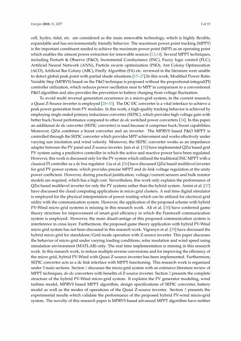
The proposed structure of the PV-Wind micro grid system is shown in Figure 1. The micro gridsystem contains a PV generator, a Wind Turbine, a battery system and the power electronic convertertopologies. To analyze the proposed system, the equivalent circuit with two diode models for thePV generator has been used because of its better power extraction capability when compared withthe single diode model. The rotor of the wind turbine is mechanically tied to a generator to produceelectrical power. A wind turbine is a complex system, but a reasonably simple representation is possibleby modeling the aerodynamic torque or power based on turbine characteristics (non-dimensionalcurves of the power coefficient). A battery solution is also necessary to balance the stochasticfluctuations of photovoltaic (PV) power and wind power injected to the grid/load. In this section,a short description about how these main components of the proposed micro grid system have beenmodeled are presented.
Energies 2018, 11, x 3 of 15
2. Hybrid PV‐Wind Micro Grid Structure
The proposed structure of the PV‐Wind micro grid system is shown in Figure 1. The micro grid
system contains a PV generator, a Wind Turbine, a battery system and the power electronic converter
topologies. To analyze the proposed system, the equivalent circuit with two diode models for the PV
generator has been used because of its better power extraction capability when compared with the
single diode model. The rotor of the wind turbine is mechanically tied to a generator to produce
electrical power. A wind turbine is a complex system, but a reasonably simple representation is
possible by modeling the aerodynamic torque or power based on turbine characteristics (non‐
dimensional curves of the power coefficient). A battery solution is also necessary to balance the
stochastic fluctuations of photovoltaic (PV) power and wind power injected to the grid/load. In this
section, a short description about how these main components of the proposed micro grid system
have been modeled are presented.
Figure 1. A block diagram with the structure of Hybrid PV‐Wind micro grid system.
2.1. PVG Mathematical Model
Figure 2 illustrates the basic PV cell schematic diagram, which is responsible for the
transformation of the solar energy into electric power using photoelectric effect which comprises
numerous cells. In this paper, the two‐diode model is considered to deliver better accuracy compared
to the single diode model.
The PV cell output current is expressed mathematically as:
(1)
Also, Photon current is evaluated mathematically as:
_ (2)
Diode saturation current can be expressed as:
_
_1
(3)
Figure 1. A block diagram with the structure of Hybrid PV-Wind micro grid system.
2.1. PVG Mathematical Model
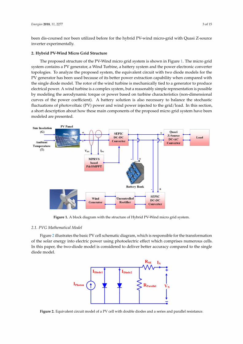
Figure 2 illustrates the basic PV cell schematic diagram, which is responsible for the transformationof the solar energy into electric power using photoelectric effect which comprises numerous cells.In this paper, the two-diode model is considered to deliver better accuracy compared to the singlediode model.Energies 2018, 11, x 4 of 15
Figure 2. Equivalent circuit model of a PV cell with double diodes and a series and parallel resistance.
2.2. Wind Turbine Modeling
A wind turbine is essentially a machine that converts the kinetic energy first into mechanical
energy at the turbine shaft, and then into electrical energy. The wind turbine power generation
depends mainly on wind velocity in which the rotors are mechanically linked to a generator. A simple
model can be achieved by using the power coefficient (CPR) as a function of tip speed ration and the
blade pitch angle. CPR (Performance/power coefficient) Vs tip speed (λT.S) curve is plotted for
different βP.B (Pitch blade angle) in Figure 3.
Figure 3. CPR (Performance coefficient) Vs tip speed (λT.S) curve is plotted for different βP.B (Pitch
blade angle).
Generated mechanical power output from the wind turbine can be written using Equation (4)
which is depending on wind velocity (VWind), RT (Turbine radius) and CPR (Performance coefficient) as:
12 . (4)
Also, the ratio of tip speed (λT.S) can be described mathematically which is correlated with an
angular velocity of the blade (ωA.V), VWind and RT as:
..
(5)
And coefficient of performance is expressed with λT.S and βP.B (Pitch blade angle) as:
. , . 0.72150
2 10 . 131 10 (6)
where,
1 1
. 8 10 .
35 101 .
(7)
. ƞ (8)
Figure 2. Equivalent circuit model of a PV cell with double diodes and a series and parallel resistance.
Energies 2018, 11, 2277 4 of 15
The PV cell output current is expressed mathematically as:
IN = IPhoton − IDiode1 − IDiode2 −(
VN + IN RSERParallel
)(1)
Also, Photon current is evaluated mathematically as:
IPhoton = [IPhoton_STC + KS(TC − TSTC)]×G
GSTC(2)
Diode saturation current can be expressed as:
IDiode1 = IDiode2 =IShort_STC + KS(TC − TSTC)
exp [(Vopen_STC+KVL(TC−TSTC))]
VThermal− 1
(3)
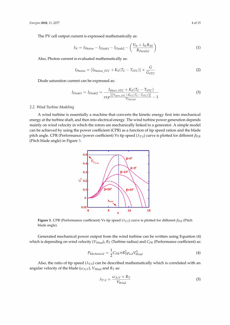
2.2. Wind Turbine Modeling
A wind turbine is essentially a machine that converts the kinetic energy first into mechanicalenergy at the turbine shaft, and then into electrical energy. The wind turbine power generation dependsmainly on wind velocity in which the rotors are mechanically linked to a generator. A simple modelcan be achieved by using the power coefficient (CPR) as a function of tip speed ration and the bladepitch angle. CPR (Performance/power coefficient) Vs tip speed (λT.S) curve is plotted for different βP.B(Pitch blade angle) in Figure 3.
Energies 2018, 11, x 4 of 15
Figure 2. Equivalent circuit model of a PV cell with double diodes and a series and parallel resistance.
2.2. Wind Turbine Modeling
A wind turbine is essentially a machine that converts the kinetic energy first into mechanical
energy at the turbine shaft, and then into electrical energy. The wind turbine power generation
depends mainly on wind velocity in which the rotors are mechanically linked to a generator. A simple
model can be achieved by using the power coefficient (CPR) as a function of tip speed ration and the
blade pitch angle. CPR (Performance/power coefficient) Vs tip speed (λT.S) curve is plotted for
different βP.B (Pitch blade angle) in Figure 3.
Figure 3. CPR (Performance coefficient) Vs tip speed (λT.S) curve is plotted for different βP.B (Pitch
blade angle).
Generated mechanical power output from the wind turbine can be written using Equation (4)
which is depending on wind velocity (VWind), RT (Turbine radius) and CPR (Performance coefficient) as:
12 . (4)
Also, the ratio of tip speed (λT.S) can be described mathematically which is correlated with an
angular velocity of the blade (ωA.V), VWind and RT as:
..
(5)
And coefficient of performance is expressed with λT.S and βP.B (Pitch blade angle) as:
. , . 0.72150
2 10 . 131 10 (6)
where,
1 1
. 8 10 .
35 101 .
(7)
. ƞ (8)
Figure 3. CPR (Performance coefficient) Vs tip speed (λT.S) curve is plotted for different βP.B (Pitchblade angle).
Generated mechanical power output from the wind turbine can be written using Equation (4)which is depending on wind velocity (VWind), RT (Turbine radius) and CPR (Performance coefficient) as:
PMechanical =12
CPRπR2Tρa.dV3
Wind (4)
Also, the ratio of tip speed (λT.S) can be described mathematically which is correlated with anangular velocity of the blade (ωA.V), VWind and RT as:
λT.S =ωA.V × RT
VWind(5)
Energies 2018, 11, 2277 5 of 15
And coefficient of performance is expressed with λT.S and βP.B (Pitch blade angle) as:
CPR(λT.S, βP.B) = 0.72
[150λj
− 2 × 10⁻³βP.B − 131 × 10−1
]e−185×10−1
λj (6)
where,1λj
=1
(λT.S + 8 × 10⁻²βP.B)− 35 × 10−3
1 + β3P.B
(7)
λT.S =ωG × RT
VWind × ηgear(8)
ηgear =ωGM × RTλT.SVWind
(9)
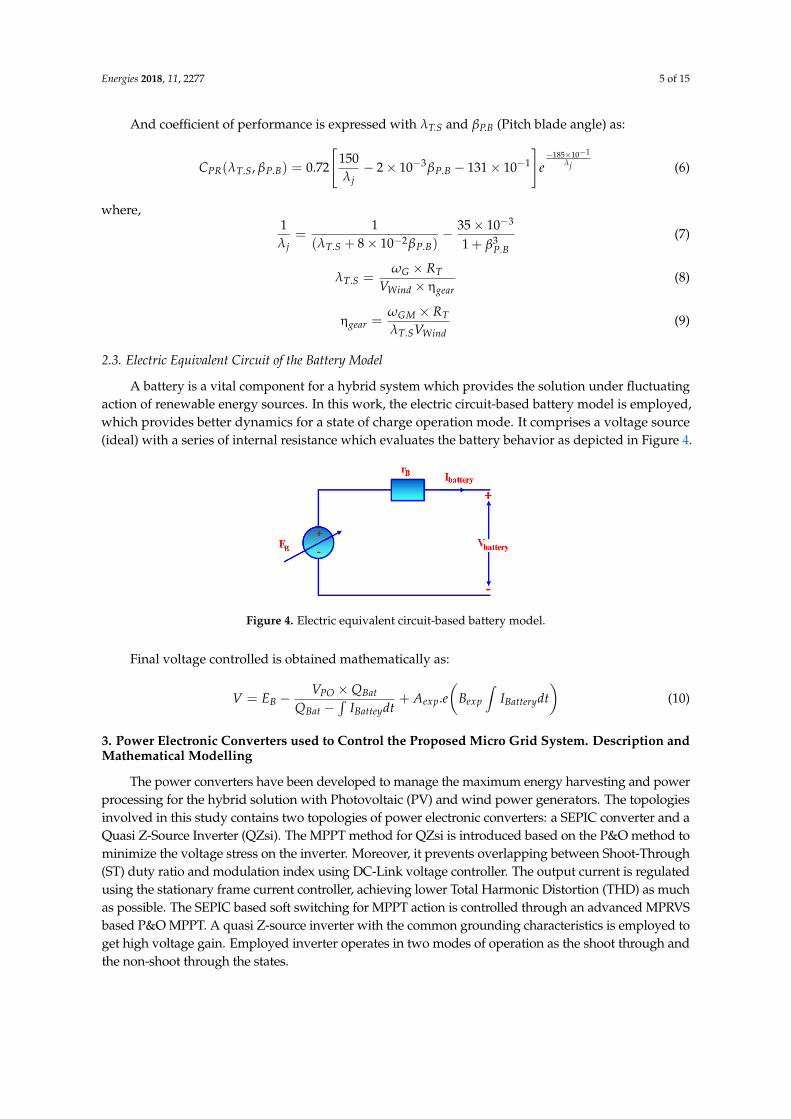
2.3. Electric Equivalent Circuit of the Battery Model
A battery is a vital component for a hybrid system which provides the solution under fluctuatingaction of renewable energy sources. In this work, the electric circuit-based battery model is employed,which provides better dynamics for a state of charge operation mode. It comprises a voltage source(ideal) with a series of internal resistance which evaluates the battery behavior as depicted in Figure 4.
Energies 2018, 11, x 5 of 15
ƞ.
(9)
2.3.Electric Equivalent Circuit of the Battery Model
A battery is a vital component for a hybrid system which provides the solution under fluctuating
action of renewable energy sources. In this work, the electric circuit‐based battery model is employed,
which provides better dynamics for a state of charge operation mode. It comprises a voltage source
(ideal) with a series of internal resistance which evaluates the battery behavior as depicted in Figure 4.
Figure 4. Electric equivalent circuit‐based battery model.
Final voltage controlled is obtained mathematically as:
. ( ) (10)
3. Power Electronic Converters used to Control the Proposed Micro Grid System. Description
and Mathematical Modelling
The power converters have been developed to manage the maximum energy harvesting and
power processing for the hybrid solution with Photovoltaic (PV) and wind power generators. The
topologies involved in this study contains two topologies of power electronic converters: a SEPIC
converter and a Quasi Z‐Source Inverter (QZsi). The MPPT method for QZsi is introduced based on
the P&O method to minimize the voltage stress on the inverter. Moreover, it prevents overlapping
between Shoot‐Through (ST) duty ratio and modulation index using DC‐Link voltage controller. The
output current is regulated using the stationary frame current controller, achieving lower Total
Harmonic Distortion (THD) as much as possible. The SEPIC based soft switching for MPPT action is
controlled through an advanced MPRVS based P&O MPPT. A quasi Z‐source inverter with the
common grounding characteristics is employed to get high voltage gain. Employed inverter operates
in two modes of operation as the shoot through and the non‐shoot through the states.
3.1. SEPIC Converter Model
Single ended primary inductor converter (SEPIC) is considered as an impedance adapter
between the PV module and the Z‐source inverter as it provides high gain throughout the operation,
better voltage performance and high voltage rating for lower/higher power requirements. When
boost converter combines with the additional inductor and the capacitor, a SEPIC converter is
developed. In contrast with the buck boost converter, the polarity of SEPIC is kept positively as it is
depicted in Figure 5. Table 1 portrays the employed SEPIC converter parameters during an
implementation.
1 (11)
∆ (12)
Figure 4. Electric equivalent circuit-based battery model.
Final voltage controlled is obtained mathematically as:
V = EB − VPO × QBat
QBat −∫
IBatteydt+ Aexp.e
(Bexp
∫IBatterydt
)(10)
3. Power Electronic Converters used to Control the Proposed Micro Grid System. Description andMathematical Modelling
The power converters have been developed to manage the maximum energy harvesting and powerprocessing for the hybrid solution with Photovoltaic (PV) and wind power generators. The topologiesinvolved in this study contains two topologies of power electronic converters: a SEPIC converter and aQuasi Z-Source Inverter (QZsi). The MPPT method for QZsi is introduced based on the P&O method tominimize the voltage stress on the inverter. Moreover, it prevents overlapping between Shoot-Through(ST) duty ratio and modulation index using DC-Link voltage controller. The output current is regulatedusing the stationary frame current controller, achieving lower Total Harmonic Distortion (THD) as muchas possible. The SEPIC based soft switching for MPPT action is controlled through an advanced MPRVSbased P&O MPPT. A quasi Z-source inverter with the common grounding characteristics is employed toget high voltage gain. Employed inverter operates in two modes of operation as the shoot through andthe non-shoot through the states.
Energies 2018, 11, 2277 6 of 15
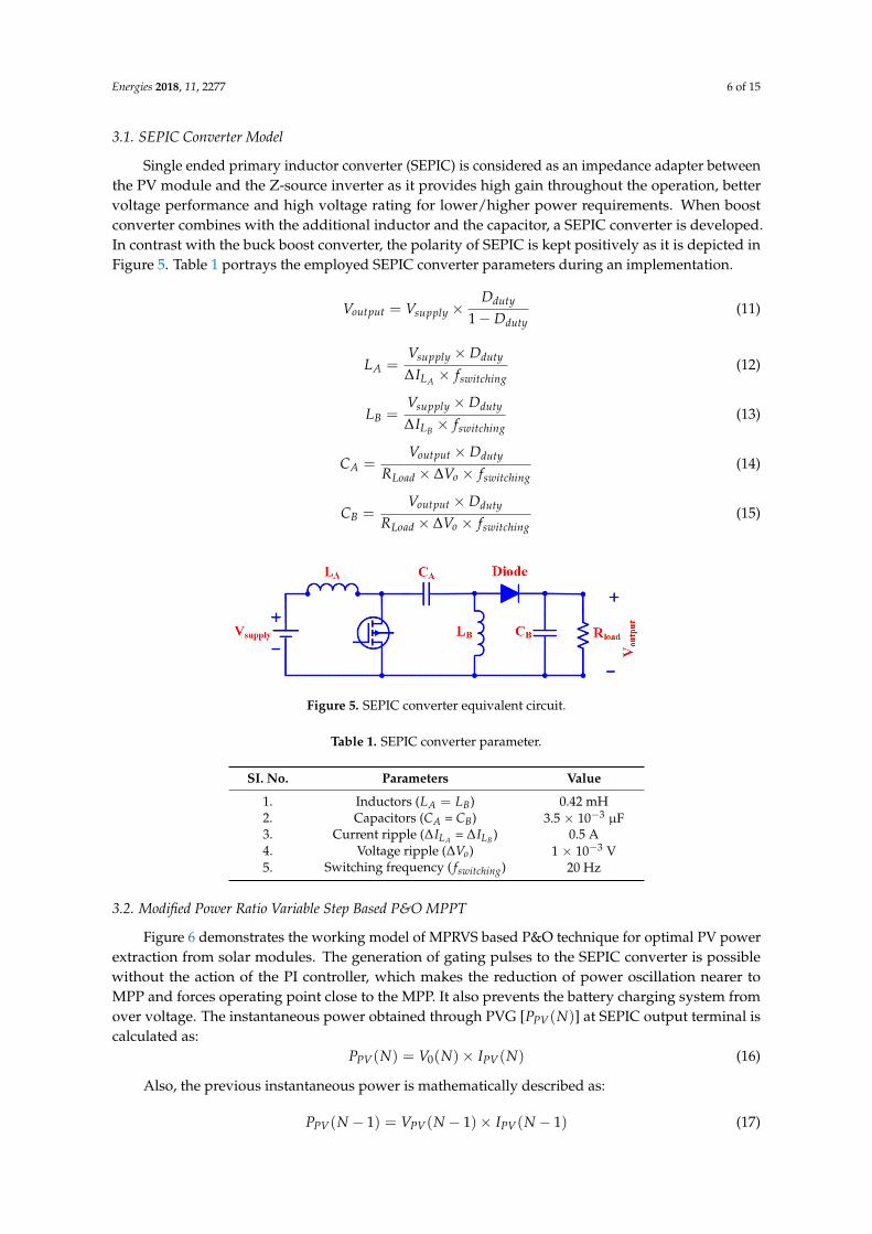
3.1. SEPIC Converter Model
Single ended primary inductor converter (SEPIC) is considered as an impedance adapter betweenthe PV module and the Z-source inverter as it provides high gain throughout the operation, bettervoltage performance and high voltage rating for lower/higher power requirements. When boostconverter combines with the additional inductor and the capacitor, a SEPIC converter is developed.In contrast with the buck boost converter, the polarity of SEPIC is kept positively as it is depicted inFigure 5. Table 1 portrays the employed SEPIC converter parameters during an implementation.
Voutput = Vsupply ×Dduty
1 − Dduty(11)
LA =Vsupply × Dduty
∆ILA × fswitching(12)
LB =Vsupply × Dduty
∆ILB × fswitching(13)
CA =Voutput × Dduty
RLoad × ∆Vo × fswitching(14)
CB =Voutput × Dduty
RLoad × ∆Vo × fswitching(15)
Energies 2018, 11, x 6 of 15
∆ (13)
∆ (14)
∆ (15)
Figure 5. SEPIC converter equivalent circuit.
Table 1. SEPIC converter parameter.
SI. No. Parameters Value
1. Inductors ( ) 0.42 mH
2. Capacitors ( = ) 3.5 × 10⁻³ μF
3. Current ripple (∆ =∆ ) 0.5 A
4. Voltage ripple (∆ ) 1 × 10⁻³ V
5. Switching frequency ( ) 20 Hz
3.2. Modified Power Ratio Variable Step Based P&O MPPT
Figure 6 demonstrates the working model of MPRVS based P&O technique for optimal PV
power extraction from solar modules. The generation of gating pulses to the SEPIC converter is
possible without the action of the PI controller, which makes the reduction of power oscillation nearer
to MPP and forces operating point close to the MPP. It also prevents the battery charging system from
over voltage. The instantaneous power obtained through PVG [ ] at SEPIC output terminal is
calculated as:
(16)
Also, the previous instantaneous power is mathematically described as:
1 1 1 (17)
And if
∆ 1 0, S = −1 (18)
& 1 0,S = +1 (19)
Again,
1 ∆ (20)
∆ = Step perturbation of duty ratio =
dT = Fixed step size
K = Variable power ratio
(21)
Figure 5. SEPIC converter equivalent circuit.
Table 1. SEPIC converter parameter.
SI. No. Parameters Value
1. Inductors (LA = LB) 0.42 mH2. Capacitors (CA = CB) 3.5 × 10⁻³ µF3. Current ripple (∆ILA = ∆ILB ) 0.5 A4. Voltage ripple (∆Vo) 1 × 10⁻³ V5. Switching frequency ( fswitching) 20 Hz
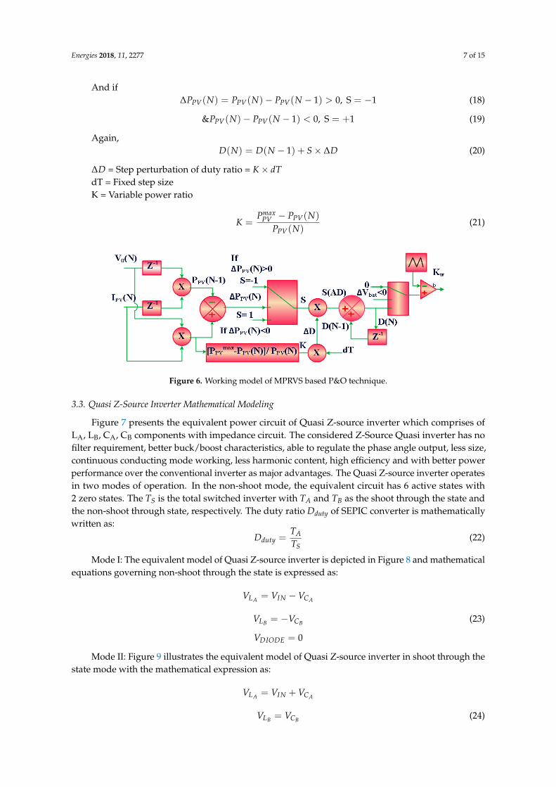
3.2. Modified Power Ratio Variable Step Based P&O MPPT
Figure 6 demonstrates the working model of MPRVS based P&O technique for optimal PV powerextraction from solar modules. The generation of gating pulses to the SEPIC converter is possiblewithout the action of the PI controller, which makes the reduction of power oscillation nearer toMPP and forces operating point close to the MPP. It also prevents the battery charging system fromover voltage. The instantaneous power obtained through PVG [PPV(N)] at SEPIC output terminal iscalculated as:
PPV(N) = V0(N)× IPV(N) (16)
Also, the previous instantaneous power is mathematically described as:
PPV(N − 1) = VPV(N − 1)× IPV(N − 1) (17)
Energies 2018, 11, 2277 7 of 15
And if∆PPV(N) = PPV(N)− PPV(N − 1) > 0, S = −1 (18)
&PPV(N)− PPV(N − 1) < 0, S = +1 (19)
Again,D(N) = D(N − 1) + S × ∆D (20)
∆D = Step perturbation of duty ratio = K × dTdT = Fixed step sizeK = Variable power ratio
K =Pmax
PV − PPV(N)
PPV(N)(21)
Energies 2018, 11, x 7 of 15
Figure 6. Working model of MPRVS based P&O technique.
3.3. Quasi Z‐Source Inverter Mathematical Modeling
Figure 7 presents the equivalent power circuit of Quasi Z‐source inverter which comprises of LA,
LB, CA, CB components with impedance circuit. The considered Z‐Source Quasi inverter has no filter
requirement, better buck/boost characteristics, able to regulate the phase angle output, less size,
continuous conducting mode working, less harmonic content, high efficiency and with better power
performance over the conventional inverter as major advantages. The Quasi Z‐source inverter
operates in two modes of operation. In the non‐shoot mode, the equivalent circuit has 6 active states
with 2 zero states. The TS is the total switched inverter with TA and TB as the shoot through the state
and the non‐shoot through state, respectively. The duty ratio Dduty of SEPIC converter is
mathematically written as:
(22)
Mode I: The equivalent model of Quasi Z‐source inverter is depicted in Figure 8 and
mathematical equations governing non‐shoot through the state is expressed as:
(23)
0
Mode II: Figure 9 illustrates the equivalent model of Quasi Z‐source inverter in shoot through
the state mode with the mathematical expression as:
(24)
Figure 7. Equivalent power circuit of Quasi Z‐source inverter.
Figure 6. Working model of MPRVS based P&O technique.
3.3. Quasi Z-Source Inverter Mathematical Modeling
Figure 7 presents the equivalent power circuit of Quasi Z-source inverter which comprises ofLA, LB, CA, CB components with impedance circuit. The considered Z-Source Quasi inverter has nofilter requirement, better buck/boost characteristics, able to regulate the phase angle output, less size,continuous conducting mode working, less harmonic content, high efficiency and with better powerperformance over the conventional inverter as major advantages. The Quasi Z-source inverter operatesin two modes of operation. In the non-shoot mode, the equivalent circuit has 6 active states with2 zero states. The TS is the total switched inverter with TA and TB as the shoot through the state andthe non-shoot through state, respectively. The duty ratio Dduty of SEPIC converter is mathematicallywritten as:
Dduty =TATS
(22)
Mode I: The equivalent model of Quasi Z-source inverter is depicted in Figure 8 and mathematicalequations governing non-shoot through the state is expressed as:
VLA = VIN − VCA
VLB = −VCB (23)
VDIODE = 0
Mode II: Figure 9 illustrates the equivalent model of Quasi Z-source inverter in shoot through thestate mode with the mathematical expression as:
VLA = VIN + VCA
VLB = VCB (24)
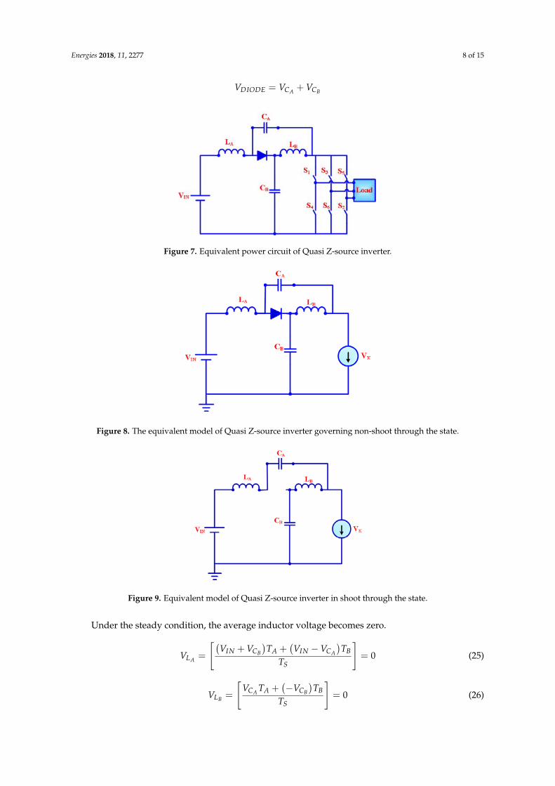
Energies 2018, 11, 2277 8 of 15
VDIODE = VCA + VCB
Energies 2018, 11, x 7 of 15
Figure 6. Working model of MPRVS based P&O technique.
3.3. Quasi Z‐Source Inverter Mathematical Modeling
Figure 7 presents the equivalent power circuit of Quasi Z‐source inverter which comprises of LA,
LB, CA, CB components with impedance circuit. The considered Z‐Source Quasi inverter has no filter
requirement, better buck/boost characteristics, able to regulate the phase angle output, less size,
continuous conducting mode working, less harmonic content, high efficiency and with better power
performance over the conventional inverter as major advantages. The Quasi Z‐source inverter
operates in two modes of operation. In the non‐shoot mode, the equivalent circuit has 6 active states
with 2 zero states. The TS is the total switched inverter with TA and TB as the shoot through the state
and the non‐shoot through state, respectively. The duty ratio Dduty of SEPIC converter is
mathematically written as:
(22)
Mode I: The equivalent model of Quasi Z‐source inverter is depicted in Figure 8 and
mathematical equations governing non‐shoot through the state is expressed as:
(23)
0
Mode II: Figure 9 illustrates the equivalent model of Quasi Z‐source inverter in shoot through
the state mode with the mathematical expression as:
(24)
Figure 7. Equivalent power circuit of Quasi Z‐source inverter. Figure 7. Equivalent power circuit of Quasi Z-source inverter.Energies 2018, 11, x 8 of 15
Figure 8. The equivalent model of Quasi Z‐source inverter governing non‐shoot through the state.
Figure 9. Equivalent model of Quasi Z‐source inverter in shoot through the state.
Under the steady condition, the average inductor voltage becomes zero.
0 (25)
0 (26)
On solving the above equations, capacitor voltage ( & ) is calculated mathematically as:
(27)
(28)
Maximum voltage across DC‐link = (29)
Putting Equations (26) and (27) in (28) we get
Maximum DC‐link voltage = (30)
4. Experimental Setup Description and Results
4.1. Description of the Experimental Setup
The considered hybrid PV‐Wind micro grid is tested using MPRVS based P&O MPPT with
employed Z‐source inverter. Figure 10 depicts the developed practical structure of the proposed
hybrid micro grid based on a real‐time platform, dSPACE. The SEPIC converter is controlled through
the MPRVS based P&O based MPPT, in which LV‐25P and LA‐25P, current and voltage sensors are
Figure 8. The equivalent model of Quasi Z-source inverter governing non-shoot through the state.
Energies 2018, 11, x 8 of 15
Figure 8. The equivalent model of Quasi Z‐source inverter governing non‐shoot through the state.
Figure 9. Equivalent model of Quasi Z‐source inverter in shoot through the state.
Under the steady condition, the average inductor voltage becomes zero.
0 (25)
0 (26)
On solving the above equations, capacitor voltage ( & ) is calculated mathematically as:
(27)
(28)
Maximum voltage across DC‐link = (29)
Putting Equations (26) and (27) in (28) we get
Maximum DC‐link voltage = (30)
4. Experimental Setup Description and Results
4.1. Description of the Experimental Setup
The considered hybrid PV‐Wind micro grid is tested using MPRVS based P&O MPPT with
employed Z‐source inverter. Figure 10 depicts the developed practical structure of the proposed
hybrid micro grid based on a real‐time platform, dSPACE. The SEPIC converter is controlled through
the MPRVS based P&O based MPPT, in which LV‐25P and LA‐25P, current and voltage sensors are
Figure 9. Equivalent model of Quasi Z-source inverter in shoot through the state.
Under the steady condition, the average inductor voltage becomes zero.
VLA =
[(VIN + VCB
)TA +
(VIN − VCA
)TB
TS
]= 0 (25)
VLB =
[VCA TA +
(−VCB
)TB
TS
]= 0 (26)
Energies 2018, 11, 2277 9 of 15
On solving the above equations, capacitor voltage (VCA &VCB ) is calculated mathematically as:
VCA =
(TB
TB − TA
)× VIN (27)
VCB =
(TA
TB − TA
)× VIN (28)
Maximum voltage across DC-link = VCA + VCB (29)
Putting Equations (26) and (27) in (28) we get
Maximum DC-link voltage =
∣∣∣∣∣ 1
1 − 2 TATS
∣∣∣∣∣VIN = K × VIN (30)
4. Experimental Setup Description and Results
4.1. Description of the Experimental Setup
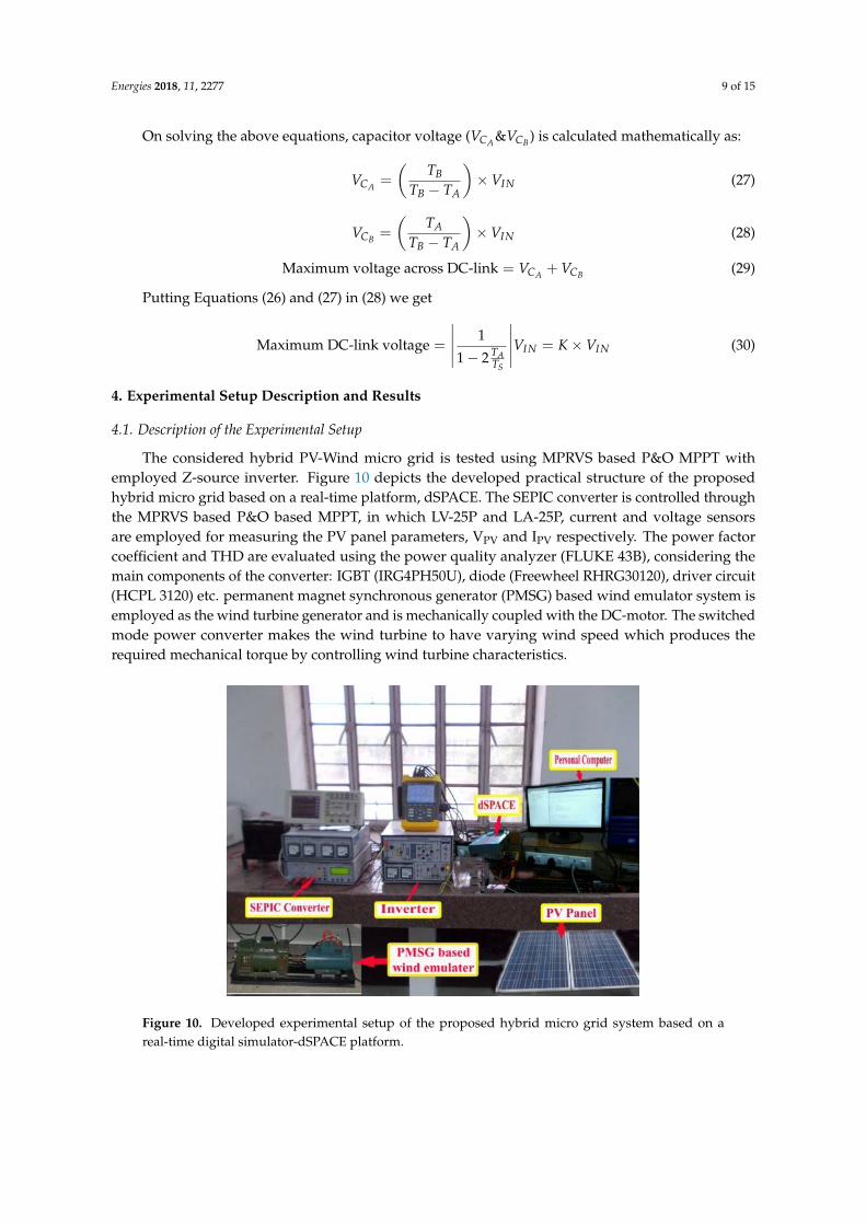
The considered hybrid PV-Wind micro grid is tested using MPRVS based P&O MPPT withemployed Z-source inverter. Figure 10 depicts the developed practical structure of the proposedhybrid micro grid based on a real-time platform, dSPACE. The SEPIC converter is controlled throughthe MPRVS based P&O based MPPT, in which LV-25P and LA-25P, current and voltage sensorsare employed for measuring the PV panel parameters, VPV and IPV respectively. The power factorcoefficient and THD are evaluated using the power quality analyzer (FLUKE 43B), considering themain components of the converter: IGBT (IRG4PH50U), diode (Freewheel RHRG30120), driver circuit(HCPL 3120) etc. permanent magnet synchronous generator (PMSG) based wind emulator system isemployed as the wind turbine generator and is mechanically coupled with the DC-motor. The switchedmode power converter makes the wind turbine to have varying wind speed which produces therequired mechanical torque by controlling wind turbine characteristics.
Energies 2018, 11, x 9 of 15
employed for measuring the PV panel parameters, VPV and IPV respectively. The power factor
coefficient and THD are evaluated using the power quality analyzer (FLUKE 43B), considering the
main components of the converter: IGBT (IRG4PH50U), diode (Freewheel RHRG30120), driver circuit
(HCPL 3120) etc. permanent magnet synchronous generator (PMSG) based wind emulator system is
employed as the wind turbine generator and is mechanically coupled with the DC‐motor. The
switched mode power converter makes the wind turbine to have varying wind speed which produces
the required mechanical torque by controlling wind turbine characteristics.
Figure 10. Developed experimental setup of the proposed hybrid micro grid system based on a real‐
time digital simulator‐dSPACE platform.
4.2. Experimental Results and Scenarious Development
The accuracy of the proposed MPRVS based P&O MPPT has been tested with changing wind
operating condition depicted in Figure 11a. The employed controller works in MPP area and provides
optimal tracking of wind power under the sudden changes of wind velocity shown in Figure 11b.The
corresponding duty ratio of SEPIC converter is shown in Figure 11c. Furthermore, the capability of
proposed MPPT tracker is examined under the first scenarios with step varying solar irradiation.
Figure 12 demonstrates that the PV array has obtained parameters under the step‐changes in solar
irradiation and the propped system has proved high accuracy and effective PV tracking in MPP
region. The obtained experimental results in Figure 13a illustrate that the performance of the
proposed hybrid micro grid under the second scenarios by varying wind velocity and constant solar
irradiation. Also, Figure 13b demonstrates the behavior responses of the hybrid micro grid under
varying solar irradiance and constant wind velocity with MPRVS based P&O MPPT employed. The
performance of the hybrid micro grid is also tested under the third proposed scenarios in the absence
of wind velocity and during this operation: the load is connected/disconnected to the utility grid,
which is shown in Figure 14a under the load cutting condition, and in Figure 14b, under the load
removing conditions. The performance of the wind generator is evaluated under
disconnecting/reconnecting operating conditions to the micro grid, which are depicted in Figures 15
and 16 and reveal that the accurate performance of the proposed hybrid micro grid in varying
operating situations (disconnecting operating conditions to the micro grid and reconnecting
operating conditions to the micro grid), respectively.
Figure 10. Developed experimental setup of the proposed hybrid micro grid system based on areal-time digital simulator-dSPACE platform.
Energies 2018, 11, 2277 10 of 15
4.2. Experimental Results and Scenarious Development
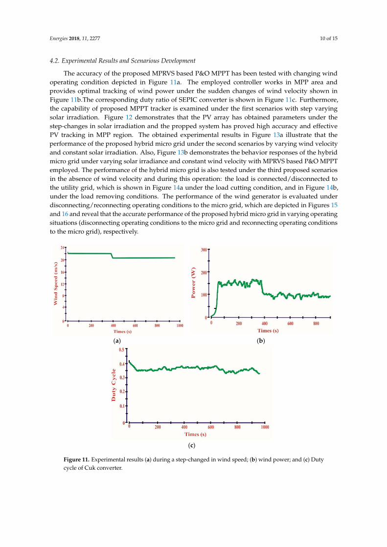
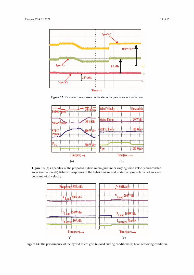
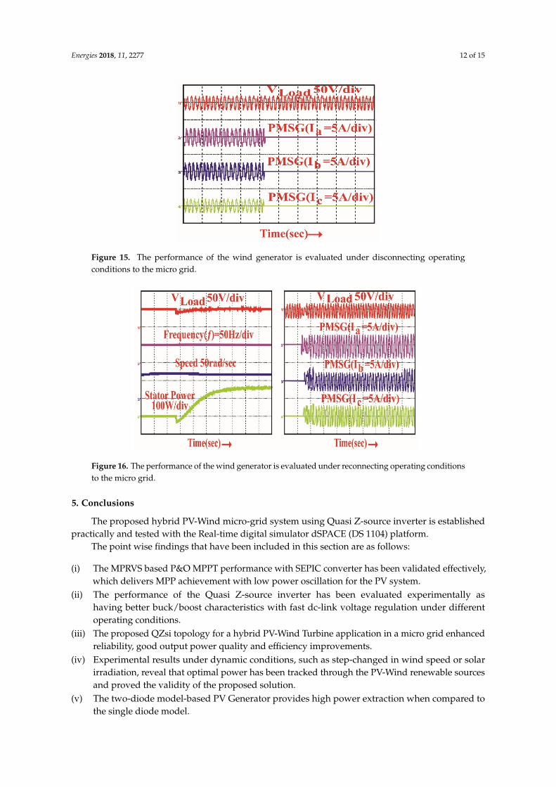
The accuracy of the proposed MPRVS based P&O MPPT has been tested with changing windoperating condition depicted in Figure 11a. The employed controller works in MPP area andprovides optimal tracking of wind power under the sudden changes of wind velocity shown inFigure 11b.The corresponding duty ratio of SEPIC converter is shown in Figure 11c. Furthermore,the capability of proposed MPPT tracker is examined under the first scenarios with step varyingsolar irradiation. Figure 12 demonstrates that the PV array has obtained parameters under thestep-changes in solar irradiation and the propped system has proved high accuracy and effectivePV tracking in MPP region. The obtained experimental results in Figure 13a illustrate that theperformance of the proposed hybrid micro grid under the second scenarios by varying wind velocityand constant solar irradiation. Also, Figure 13b demonstrates the behavior responses of the hybridmicro grid under varying solar irradiance and constant wind velocity with MPRVS based P&O MPPTemployed. The performance of the hybrid micro grid is also tested under the third proposed scenariosin the absence of wind velocity and during this operation: the load is connected/disconnected tothe utility grid, which is shown in Figure 14a under the load cutting condition, and in Figure 14b,under the load removing conditions. The performance of the wind generator is evaluated underdisconnecting/reconnecting operating conditions to the micro grid, which are depicted in Figures 15and 16 and reveal that the accurate performance of the proposed hybrid micro grid in varying operatingsituations (disconnecting operating conditions to the micro grid and reconnecting operating conditionsto the micro grid), respectively.Energies 2018, 11, x 10 of 15
(a) (b)
(c)
Figure 11. Experimental results (a) during a step‐changed in wind speed; (b) wind power; and(c) Duty
cycle of Cuk converter.
Figure 12. PV system responses under step‐changes in solar irradiation.
Figure 11. Experimental results (a) during a step-changed in wind speed; (b) wind power; and (c) Dutycycle of Cuk converter.
Energies 2018, 11, 2277 11 of 15
Energies 2018, 11, x 10 of 15
(a) (b)
(c)
Figure 11. Experimental results (a) during a step‐changed in wind speed; (b) wind power; and(c) Duty
cycle of Cuk converter.
Figure 12. PV system responses under step‐changes in solar irradiation. Figure 12. PV system responses under step-changes in solar irradiation.Energies 2018, 11, x 11 of 15
(a) (b)
Figure 13. (a) Capability of the proposed hybrid micro grid under varying wind velocity and constant
solar irradiation; (b) Behavior responses of the hybrid micro grid under varying solar irradiance and
constant wind velocity.
(a) (b)
Figure 14. The performance of the hybrid micro grid (a) load cutting condition; (b) Load removing
condition.
Figure 15. The performance of the wind generator is evaluated under disconnecting operating
conditions to the micro grid.
Figure 13. (a) Capability of the proposed hybrid micro grid under varying wind velocity and constantsolar irradiation; (b) Behavior responses of the hybrid micro grid under varying solar irradiance andconstant wind velocity.
Energies 2018, 11, x 11 of 15
(a) (b)
Figure 13. (a) Capability of the proposed hybrid micro grid under varying wind velocity and constant
solar irradiation; (b) Behavior responses of the hybrid micro grid under varying solar irradiance and
constant wind velocity.
(a) (b)
Figure 14. The performance of the hybrid micro grid (a) load cutting condition; (b) Load removing
condition.
Figure 15. The performance of the wind generator is evaluated under disconnecting operating
conditions to the micro grid.
Figure 14. The performance of the hybrid micro grid (a) load cutting condition; (b) Load removing condition.
Energies 2018, 11, 2277 12 of 15
Energies 2018, 11, x 11 of 15
(a) (b)
Figure 13. (a) Capability of the proposed hybrid micro grid under varying wind velocity and constant
solar irradiation; (b) Behavior responses of the hybrid micro grid under varying solar irradiance and
constant wind velocity.
(a) (b)
Figure 14. The performance of the hybrid micro grid (a) load cutting condition; (b) Load removing
condition.
Figure 15. The performance of the wind generator is evaluated under disconnecting operating
conditions to the micro grid. Figure 15. The performance of the wind generator is evaluated under disconnecting operatingconditions to the micro grid.Energies 2018, 11, x 12 of 15
Figure 16. The performance of the wind generator is evaluated under reconnecting operating
conditions to the micro grid.
5. Conclusions
The proposed hybrid PV‐Wind micro‐grid system using Quasi Z‐source inverter is established
practically and tested with the Real‐time digital simulator dSPACE (DS 1104) platform.
The point wise findings that have been included in this section are as follows:
(i) The MPRVS based P&O MPPT performance with SEPIC converter has been validated
effectively, which delivers MPP achievement with low power oscillation for the PV system.
(ii) The performance of the Quasi Z‐source inverter has been evaluated experimentally as having
better buck/boost characteristics with fast dc‐link voltage regulation under different operating
conditions.
(iii) The proposed QZsi topology for a hybrid PV‐Wind Turbine application in a micro grid enhanced
reliability, good output power quality and efficiency improvements.
(iv) Experimental results under dynamic conditions, such as step‐changed in wind speed or solar
irradiation, reveal that optimal power has been tracked through the PV‐Wind renewable sources
and proved the validity of the proposed solution.
(v) The two‐diode model‐based PV Generator provides high power extraction when compared to
the single diode model.
As a future work, the paper can be extended by using the multilevel inverter with the application
of advanced intelligent MPPT algorithms viz. Jaya DE, hybrid ANFIS‐ABC methods.
Author Contributions: All authors contributed equally and formulated the research work to present in current
version as full research article.
Funding: No funding addressed to this research activities.
Conflicts of Interest: The authors declare no conflict of interest.
Nomenclature
RSE Resistance in series
RParallel Resistance in parallel
TSTC Temperature at STC (Standard Test Condition)
GSTC Solar irradiance at STC
KS Coefficient of short circuit current
_ Photo current at STC
Ambient temperature
G Solar irradiation
IShort_STC Short circuit current at STC
Vopen_STC Open circuit current at STC
Figure 16. The performance of the wind generator is evaluated under reconnecting operating conditionsto the micro grid.
5. Conclusions
The proposed hybrid PV-Wind micro-grid system using Quasi Z-source inverter is establishedpractically and tested with the Real-time digital simulator dSPACE (DS 1104) platform.
The point wise findings that have been included in this section are as follows:
(i) The MPRVS based P&O MPPT performance with SEPIC converter has been validated effectively,which delivers MPP achievement with low power oscillation for the PV system.
(ii) The performance of the Quasi Z-source inverter has been evaluated experimentally ashaving better buck/boost characteristics with fast dc-link voltage regulation under differentoperating conditions.
(iii) The proposed QZsi topology for a hybrid PV-Wind Turbine application in a micro grid enhancedreliability, good output power quality and efficiency improvements.
(iv) Experimental results under dynamic conditions, such as step-changed in wind speed or solarirradiation, reveal that optimal power has been tracked through the PV-Wind renewable sourcesand proved the validity of the proposed solution.
(v) The two-diode model-based PV Generator provides high power extraction when compared tothe single diode model.

Energies 2018, 11, 2277 13 of 15
As a future work, the paper can be extended by using the multilevel inverter with the applicationof advanced intelligent MPPT algorithms viz. Jaya DE, hybrid ANFIS-ABC methods.
Author Contributions: All authors contributed equally and formulated the research work to present in currentversion as full research article.
Funding: No funding addressed to this research activities.
Conflicts of Interest: The authors declare no conflict of interest.
Nomenclature
RSE Resistance in seriesRParallel Resistance in parallelTSTC Temperature at STC (Standard Test Condition)GSTC Solar irradiance at STCKS Coefficient of short circuit currentIPhoton_STC Photo current at STCTC Ambient temperatureG Solar irradiationIShort_STC Short circuit current at STCVopen_STC Open circuit current at STCVThermal Diode thermal voltageKVL Voltage temperature coefficientρa,d Air density ρa,dωG Speed of generatorωGM Peak allowed generator speedηgear Gear ratioEB Battery fixed voltageVPO Polarized voltageQBat Capacity of batteryIBattery Battery currentAexp Amplitude of exponential zoneBexp Inverse time constant exponential zone∆ILA = ILB Current ripple∆V0 Ripple voltagefswitching Switched frequencyV0(N)&IPV(N) Sensed voltage and current∆D Step perturbation of duty ratiodT Fixed step sizeK Variable power ratioPI Proportional Integral
References
1. Tiwari, S.K.; Singh, B.; Goel, P.K. Design and Control of Micro-Grid fed by Renewable Energy GeneratingSources. IEEE Trans. Ind. Appl. 2018, 54, 2041–2050. [CrossRef]
2. Mi, Y.; Zhang, H.; Tian, Y.; Yang, Y.; Li, J.; Li, J.; Wang, L. Control and Operation of Hybrid Solar/WindIsolated DC Micro grid. In Proceedings of the IEEE Conference and Expo Transportation ElectrificationAsia-Pacific (ITEC Asia-Pacific), Beijing, China, 31 August–3 September 2014; pp. 1–5.
3. Shastry, A.; Suresh, K.V.; Vinayaka, K.U. Hybrid Wind-Solar Systems using Cuk-Sepic Fused Converter withQuasi-Z-Source Inverter. In Proceedings of the IEEE Power, Communication and Information TechnologyConference (PCITC), Bhubaneswar, India, 15–17 October 2015; pp. 856–861.
4. Kassem, A.M.; Zaid, S.A. Optimal Control of a Hybrid Renewable Wind/Fuel Cell Energy in Micro GridApplication. In Proceedings of the Nineteenth International Middle East Power Systems Conference (MEPCON),Shibin El Kom, Egypt, 19–21 December 2017; pp. 84–90.

Energies 2018, 11, 2277 14 of 15
5. Tiwari, S.K.; Singh, B.; Goel, P.K. Design and Control of Micro-Grid fed by Renewable Energy GeneratingSources. In Proceedings of the IEEE 6th International Conference on Power Systems (ICPS), New Delhi,India, 4–6 March 2016; pp. 1–6.
6. Ahmed, J.; Salam, Z. An Enhanced Adaptive P&O MPPT for Fast and Efficient Tracking under VaryingEnvironmental Conditions. IEEE Trans. Sustain. Energy 2018, 9, 1487–1496.
7. Vavilapalli, V.; Umashankar, S.; Sanjeevikumar, P.; Ramachandramurthy, V.K. Design and Real-TimeSimulation of an AC Voltage Regulator based Battery Charger for Large-Scale PV-Grid Energy StorageSystems. IEEE Access 2017, 5, 25158–25170. [CrossRef]
8. Hussain, S.; Alammari, R.; Jafarullah, M.; Iqbal, A.; Sanjeevikumar, P. Optimization of Hybrid RenewableEnergy System Using Iterative Filter Selection Approach. IET Renew. Power Gen. 2017, 11, 1440–1445.[CrossRef]
9. Dramohan, K.; Padmanaban, S.; Kalyanasundaram, R.; Bhaskar, M.S.; Mihet-Popa, L. Grid Synchronizationof a Seven-Phase Wind Electric Generator Using d-q PLL. Energies 2017, 10, 926. [CrossRef]
10. Szeidert, I.; Prostean, O.; Filip, I.; Vasar, C.; Mihet-Popa, L. Issues regarding the modeling and simulation ofwind energy conversion system’s components. In Proceedings of the International Conference on Automation,Quality & Testing, Robotics (AQTR 2008), Cluj-Napoca, Romania, 22–25 May 2008; pp. 225–228.
11. Mihet-Popa, L.; Bindner, H. Simulation models developed for voltage control in a distribution networkusing energy storage systems for PV penetration. In Proceedings of the 39th Annual Conference of the IEEEIndustrial Electronics Society, Vienna, Austria, 10–13 November 2013; pp. 7487–7492.
12. Maheswaran, G.; Hidayathullah, M.; Ismail, B.C.; Mihet-Popa, L.; Sanjeevikumar, P. Energy ManagementStrategy for Rural Communities’ DC Micro Grid power system structure with Maximum Penetration ofRenewable Energy Sources. Appl. Sci. 2018, 11, 585. [CrossRef]
13. Priyadarshi, N.; Kumar, V.; Yadav, K.; Vardia, M. An Experimental Study on Zeta buck-boost converterfor Application in PV system. In Handbook of Distributed Generation; Springer: Cham, Switzerland, 2017;pp. 393–406.
14. Priyadarshi, N.; Anand, A.; Sharma, A.K.; Azam, F.; Singh, V.K.; Sinha, R.K. An Experimental Implementationand Testing of GA based Maximum Power Point Tracking for PV System under Varying Ambient ConditionsUsing dSPACE DS 1104 Controller. Int. J. Renew. Energy Res. 2017, 7, 255–265.
15. Kumar, N.; Hussain, I.; Singh, B.; Panigrahi, B.K. Framework of Maximum Power Extraction from Solar PVPanel using Self Predictive Perturb and Observe Algorithm. IEEE Trans. Sustain. Energy 2017, 9, 895–903.[CrossRef]
16. Elgendy, M.A.; Zahawi, B.; Atkinson, D.J. Assessment of the Incremental Conductance Maximum PowerPoint Tracking Algorithm. IEEE Trans. Sustain. Energy 2013, 4, 108–117. [CrossRef]
17. Zamora, A.C.; Vazquez, G.; Sosa, J.M.; Rodriguez, P.R.M.; Juarez, M.A. Efficiency Based ComparativeAnalysis of Selected Classical MPPT Methods. In Proceedings of the IEEE International Autumn Meeting onPower, Electronics and Computing, Ixtapa, Mexico, 8–10 November 2017; pp. 1–6.
18. Abu-Rub, H.; Iqbal, A.; Ahmed, S.K.M.; Peng, F.Z.; Li, Y.; Baoming, G. Quasi-Z-Source Inverter-BasedPhotovoltaic Generation System with Maximum Power Tracking Control Using ANFIS. IEEE Trans.Sustain. Energy 2013, 4, 11–20. [CrossRef]
19. Mohamed, A.A.S.; Berzoy, A.; Mohammed, O. Design and Hardware Implementation of FL-MPPT Control ofPV Systems Based on GA and Small-Signal Analysis. IEEE Trans. Sustain. Energy 2017, 8, 279–290. [CrossRef]
20. Wang, L.; Singh, C. Population-Based Intelligent Search in Reliability Evaluation of Generation Systems withWind Power Penetration. IEEE Trans. Power Syst. 2008, 23, 1336–1345. [CrossRef]
21. Koad, R.B.A.; Zobaa, A.F.; El-Shahat, A. A Novel MPPT Algorithm Based on Particle Swarm Optimisationfor Photovoltaic Systems. IEEE Trans. Sustain. Energy 2017, 8, 468–476. [CrossRef]
22. Priyadarshi, N.; Sharma, A.K.; Azam, F. A Hybrid Firefly-Asymmetrical Fuzzy Logic Controller based MPPTfor PV-Wind-Fuel Grid Integration. Int. J. Renew. Energy Res. 2017, 7, 1546–1560.
23. Sundareswaran, K.; Sankar, P.; Nayak, P.S.R.; Simon, S.P.; Palani, S. Enhanced Energy Output from a PVSystem Under Partial Shaded Conditions Through Artificial Bee Colony. IEEE Trans. Sustain. Energy 2015, 6,18–209. [CrossRef]
24. Kalaam, R.N.; Muyeen, S.M.; Al-Durra, A.; Hasanien, H.N.; Al-Wahedi, K. Optimisation of controllerparameters for grid tied photovoltaic system at faulty network using artificial neural network-based cuckoosearch algorithm. IET Renew. Power Gen. 2017, 11, 1517–1526. [CrossRef]

Energies 2018, 11, 2277 15 of 15
25. Priyadarshi, N.; Padmanaban, S.; Mihet-Popa, L.; Blaabjerg, F.; Azam, F. Maximum Power Point Tracking forBrushless DC Motor-Driven Photovoltaic Pumping Systems Using a Hybrid ANFIS-FLOWER PollinationOptimization Algorithm. Energies 2018, 11, 1067. [CrossRef]
26. Priyadarshi, N.; Padmanaban, S.; Maroti, P.K.; Sharma, A. An Extensive Practical Investigation of FPSO-BasedMPPT for Grid Integrated PV System Under Variable Operating Conditions with Anti-Islanding Protection.IEEE Syst. J. 2018, PP, 1–11. [CrossRef]
27. Priyadarshi, N.; Padmanaban, S.; Bhaskar, M.S.; Blaabjerg, F.; Sharma, A. A Fuzzy SVPWM Based InverterControl Realization of Grid Integrated PV-Wind System with FPSO MPPT Algorithm for a Grid-ConnectedPV/Wind Power Generation System: Hardware Implementation. IET Electr. Power Appl. 2018, 12, 962–971.[CrossRef]
28. Alanisamy, R.; Mutawakkil, A.U.; Selvakumar, K.; Karthikeyan, D. Modelling and simulation of z sourceinverter based grid connected PV system. In Proceedings of the 2014 IEEE International Conference onComputational Intelligence and Computing Research, Coimbatore, India, 18–20 December 2014; pp. 1–4.
29. Kumaran, B.A.; Sekhar, C.S.A.; Bala, V. PV Powered Quasi Z-Source Inverter for Agricultural Water PumpingSystem. In Proceedings of the Third International Conference on Science Technology Engineering & Management(ICONSTEM), Chennai, India, 23–24 March 2017; pp. 544–549.
30. Haji-Esmaeili, M.M.; Babaei, E.; Sabahi, M. High Step-Up Quasi-Z Source DC-DC Converter. IEEE Trans.Power Electron. 2018, 1. [CrossRef]
31. Zhou, Y.; Liu, L.; Li, H. A High-Performance Photovoltaic Module-Integrated Converter (MIC) Based onCascaded Quasi-Z-Source Inverters (qZSI) Using eGaN FETs. IEEE Trans. Power Electron. 2013, 28, 2727–2738.[CrossRef]
32. Kayiranga, T.; Li, H.; Lin, X.; Shi, Y.; Li, H. Abnormal Operation State Analysis and Control of AsymmetricImpedance Network-Based Quasi-Z-Source PV Inverter (AIN-qZSI). IEEE Trans. Power Electron. 2016, 31,7642–7650. [CrossRef]
33. AsSakka, A.O.; Hassan, M.A.M.; Senjyn, T. Small signal modeling and control of PV based QZSI for gridconnected applications. In Proceedings of the 2017 International Conference on Modern Electrical andEnergy Systems (MEES), Kremenchuk, Ukraine, 15–17 November 2017. [CrossRef]
34. Tey, K.S.; Mekhilef, S.; Seyedmahmoudian, M.; Horan, B.; Oo, A.T.; Stojcevski, A. Improved DifferentialEvolution-based MPPT Algorithm using SEPIC for PV Systems under Partial Shading Conditions and LoadVariation. IEEE Trans. Ind. Inform. 2018, 1. [CrossRef]
35. Jain, S.; Shadmand, M.B.; Balog, R.S. Decoupled Active and Reactive PowerPredictive Control for PVApplications using a Grid-tied Quasi-Z-Source Inverter. IEEE J. Emerg. Sel. Top. Power Electron. 2018, 1.[CrossRef]
36. Liu, Y.; Ge, B.; Abu-Rub, H. Modelling and controller design of quasi-Z-sourcecascaded multilevelinverter-based three-phase grid-tie photovoltaic power system. IET Renew. Power Gen. 2014, 8, 925–936.[CrossRef]
37. Amini, M.H.; Broojeni, K.G.; Dragicevic, T.; Nejadpak, A.; Iyengar, S.S.; Blaabjerg, F. Application of CloudComputing in Power Routing for Clusters of MicrogridsUsing Oblivious Network Routing Algorithm.In Proceedings of the 19th European Conference on Power Electronics and Applications (EPE’17 ECCEEurope), Warsaw, Poland, 11–14 September 2017; pp. P.1–P.11.
38. Mohammadi, A.; Dehghani, M.J.; Ghazizadeh, E. Game Theoretic Spectrum Allocation in Femtocell Networksfor Smart Electric Distribution Grids. Energies 2018, 11, 1635. [CrossRef]
39. Vigneysh, T.; Kumarappan, N. Operation and Control of Hybrid Microgrid Using ZSource Converter in GridTied Mode. In Proceedings of the 2nd International Conference on Applied and T heoretical Computing andCommunication Technology (iCATccT), Bangalore, India, 21–23 July 2016; pp. 318–323.
© 2018 by the authors. Licensee MDPI, Basel, Switzerland. This article is an open accessarticle distributed under the terms and conditions of the Creative Commons Attribution(CC BY) license (http://creativecommons.org/licenses/by/4.0/).
Recommended