______________________________________________________________
14500 Coy Drive, Grass Lake, Michigan 49240
734-475-2200 E-mail: [email protected]
www.coylab.com
Humidity Control Glove
Box
Instruction Manual
Humidity Control Glove Box Instruction Manual 1
INDEX
Page #
Warranty 2
Warnings 3
1.0 Introduction
1.1 Glove Box Components Overview 4
2.0 Glove Box Assembly 7
2.1 Arm Port Plugs 8
2.2 Installation of Tubing to glove box fittings 9
2.3 Automatic Humidity Controller Assembly 9
2.4 Dehumidification Apparatus Assembly 10
2.5 Humidification Apparatus Assembly 12
2.6 Dry Nitrogen Purge System Assembly 15
3.0 Operation of Components
3.1 Automatic Humidity Controller 17
3.2 Dehumidification System (Desiccant) 18
3.3 Dry Nitrogen Purge System 19
3.4 Humidification System 19
4.0 Care and Cleaning
4.1 Care & Cleaning Dehumidification System 21
4.2 Care & Cleaning Humidification System 21
4.3 Care & Cleaning of Glove Box 22
4.4 Care of Gloveless Sleeves & Gloves 23
Humidity Control Glove Box Instruction Manual 2
WARRANTY
This product is warranted against defects in material and workmanship during the first 12 months
after original date of shipment.
The factory will, at its option, repair or replace defective material within this period at no charge
for parts and labor.
All returns or exchanges must first be authorized by COY LABORATORY PRODUCTS, INC.
PHONE: 734-475-2200
FAX: 734-475-1846
E.MAIL: [email protected]
COY LABORATORY PRODUCTS, INC.
14500 COY DRIVE
GRASS LAKE, MI 49240
The responsibility of COY LABORATORY PRODUCTS, INC., is limited to the purchase price
of this product, and COY LABORATORY PRODUCTS, INC., will not be responsible for any
Consequential damages.
This warranty does not cover damage in shipment or damages as a result of improper use or
maintenance of this product. This warranty does not cover damages caused by excessive line
transients on the AC supply line.
Humidity Control Glove Box Instruction Manual 3
WARNINGS
1. If the Glove Box is used with any type of gas purge, the
pressure regulator must not be set higher than 15 psi. Flow
Rates greater than 15 psi may damage the glove box and void
the warranty.
2. Never obstruct gas flow in or out of the Pressure Relief Valves.
3. The Polymer & Aluminum Glove Box styles are not intended
for vacuum or high pressure operation.
4. Running the humidity apparatus dry will damage the pump and void the factory warranty.
5. To improve the life expectancy of each apparatus
(humidification/dehumidification) the user should turn off the
apparatus not in use at the time with the Automatic Humidity
Controller. For example, when dehumidifying the chamber, or
when the desired set point is below ambient humidity levels,
turn the humidification switch off.
6. Only distilled water should be used with the humidification apparatus to prolong product life.
7. Never pull a vacuum on Polymer or Aluminum Glove Box.
This could crack/damage the glove box and void the warranty.
Humidity Control Glove Box Instruction Manual 4
1.0 Introduction
This Glove Box is designed for humidity control applications where there is a need to control
the humidity either below and/or above ambient conditions. It can be used in either Automatic
or Manual Control mode.
The Humidity Controller provides automatic monitoring and control of the relative humidity.
It activates the necessary system when the moisture level deviates from the adjustable set point.
The safety relief/bleed valves provide pressure relief with the control system and also
function as check valves, ensuring no moisture or contaminants enter the Glove Box in the event
of a system failure causing negative pressure.
The Manual Control requires an operator's periodic check with the supplied Hygrometer to be
sure the humidity is as desired. Then, turning the appropriate equipment pump switch "ON" or
"OFF" will control the desired level.
1.1 Glove Box Components Overview
Standard Equipment Includes:
1. ¼” Ball Valve 7. Automatic Humidity Controller
2. Pressure Relief Valve 8. Dehumidification Apparatus
3. Plug Strip 9. Added Capacity Dryer
4. Diaphragm Top (2 person units only)
5. Gloveless Sleeves & Arm Port Plugs 10. Humidification Apparatus
6. Large Side Door 11. Circulation Fan
¼” NPT Ball Valve
This ball valve located on the upper right side of the glove box (see
figure #1 page 7) can be used for purging operations. The ball valve is
equipped with a ¼” o.d. Quick Disconnect female and male fittings for
Tygon tubing. See section 2.2 (page 9) for installation of tubing and
Quick Disconnect Fittings
Never purge the glove box at a higher rate than 15 psi (with ¼” o.d. Tubing).
Doing so could over pressurize and damage the glove box.
NOTE: Damage from over pressurizing the glove box will void the warranty.
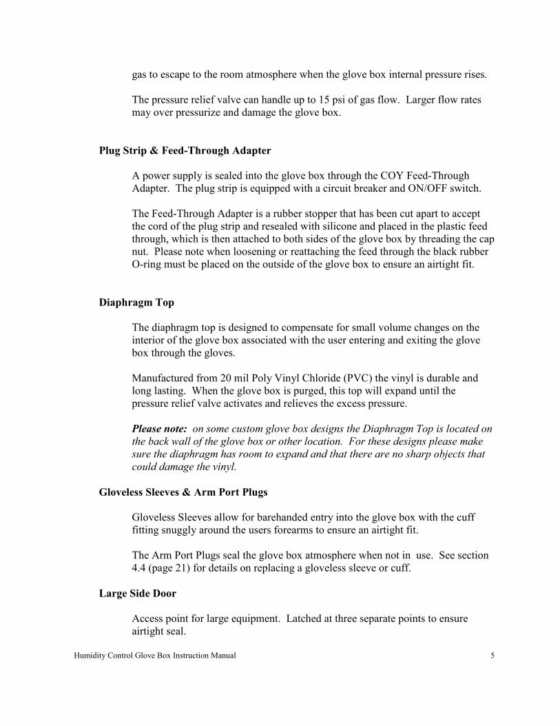
Pressure Relief Valve
The pressure relief valve relieves the glove box of large internal pressure changes
associated with gas purges. The valve is an automatic system that simply allows
Humidity Control Glove Box Instruction Manual 5
gas to escape to the room atmosphere when the glove box internal pressure rises.
The pressure relief valve can handle up to 15 psi of gas flow. Larger flow rates
may over pressurize and damage the glove box.
Plug Strip & Feed-Through Adapter
A power supply is sealed into the glove box through the COY Feed-Through
Adapter. The plug strip is equipped with a circuit breaker and ON/OFF switch.
The Feed-Through Adapter is a rubber stopper that has been cut apart to accept
the cord of the plug strip and resealed with silicone and placed in the plastic feed
through, which is then attached to both sides of the glove box by threading the cap
nut. Please note when loosening or reattaching the feed through the black rubber
O-ring must be placed on the outside of the glove box to ensure an airtight fit.
Diaphragm Top
The diaphragm top is designed to compensate for small volume changes on the
interior of the glove box associated with the user entering and exiting the glove
box through the gloves.
Manufactured from 20 mil Poly Vinyl Chloride (PVC) the vinyl is durable and
long lasting. When the glove box is purged, this top will expand until the
pressure relief valve activates and relieves the excess pressure.
Please note: on some custom glove box designs the Diaphragm Top is located on
the back wall of the glove box or other location. For these designs please make
sure the diaphragm has room to expand and that there are no sharp objects that
could damage the vinyl.
Gloveless Sleeves & Arm Port Plugs
Gloveless Sleeves allow for barehanded entry into the glove box with the cuff
fitting snuggly around the users forearms to ensure an airtight fit.
The Arm Port Plugs seal the glove box atmosphere when not in use. See section
4.4 (page 21) for details on replacing a gloveless sleeve or cuff.
Large Side Door
Access point for large equipment. Latched at three separate points to ensure
airtight seal.
Humidity Control Glove Box Instruction Manual 6
Automatic Humidity Controller
Measures and controls the humidity levels inside the glove box by turning on and
off the pumps that run the Humidification and Dehumidification Apparatus. All
based on the set-point chosen by the user. Controller is placed outside the glove
box in a convenient location for the user.
Dehumidification Apparatus
Consist of the Desiccant Cartridges mounted on the rear of the chamber and the
pump that circulates air from the glove box through the desiccant and back into
the glove box.
Added capacity dryer
Added desiccant capsules to increase time between desiccant regeneration.
Standard on all 2 person (5 & 6 ft) glove boxes. Optional on all other glove box
sizes.
Humidification Apparatus
Consist of mounted water chamber on the interior of the chamber, water reservoir
and water pump located on the exterior of the glove box. This unit adds moisture
to the glove box when pump is operational. Excess water is drained back to the
reservoir through the large drain tube.
Circulation Fan or Heated circulation fan
Circulates glove box atmosphere ensuring proper humidity mix throughout the
glove box. This unit should always be plugged in and working.
Dry Gas Purge System
An alternative means to drying the glove box by using any inert dry gas to lower
humidity levels. This automatic system has adjustable flow meters to control
drying times. The Electronic selonoid is triggered by the Automatic Controller to
allowing gas to flow into the glove box. The Automatic Pressure Relief valves
vent excess pressure. System can be used on tandem with Dehumidification
System.
Humidity Control Glove Box Instruction Manual 7
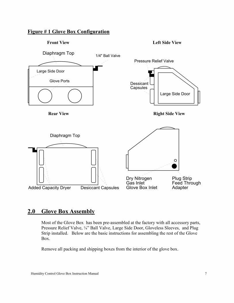
Figure # 1 Glove Box Configuration
Front View Left Side View
1/4" Ball ValveDiaphragm Top
Glove Ports
Large Side Door
Large Side Door
DessicantCapsules
Pressure Relief Valve
Rear View Right Side View
Diaphragm Top
Added Capacity Dryer Desiccant Capsules
Dry Nitrogen Plug StripFeed ThroughAdapter
Gas Inlet Glove Box Inlet
2.0 Glove Box Assembly
Most of the Glove Box has been pre-assembled at the factory with all accessory parts,
Pressure Relief Valve, ¼” Ball Valve, Large Side Door, Gloveless Sleeves, and Plug
Strip installed. Below are the basic instructions for assembling the rest of the Glove
Box.
Remove all packing and shipping boxes from the interior of the glove box.
Humidity Control Glove Box Instruction Manual 8
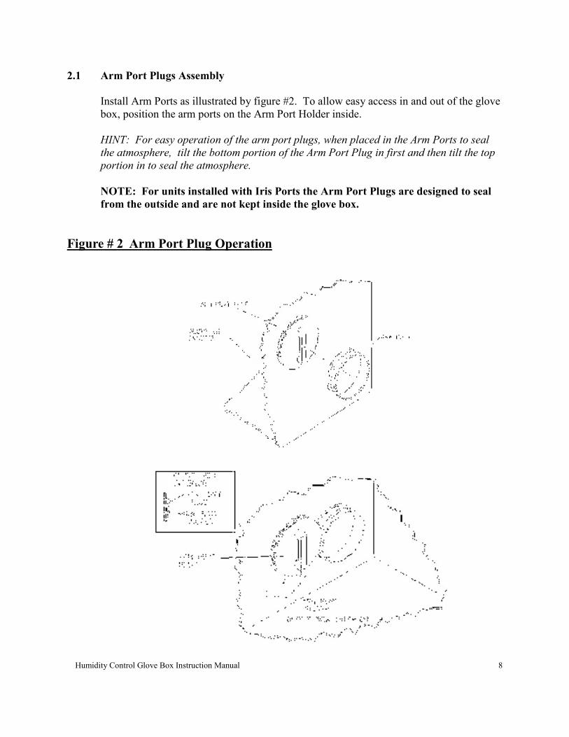
2.1 Arm Port Plugs Assembly
Install Arm Ports as illustrated by figure #2. To allow easy access in and out of the glove
box, position the arm ports on the Arm Port Holder inside.
HINT: For easy operation of the arm port plugs, when placed in the Arm Ports to seal
the atmosphere, tilt the bottom portion of the Arm Port Plug in first and then tilt the top
portion in to seal the atmosphere.
NOTE: For units installed with Iris Ports the Arm Port Plugs are designed to seal
from the outside and are not kept inside the glove box.
Figure # 2 Arm Port Plug Operation
Humidity Control Glove Box Instruction Manual 9
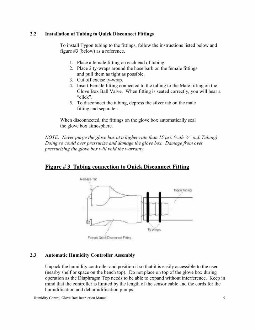
2.2 Installation of Tubing to Quick Disconnect Fittings
To install Tygon tubing to the fittings, follow the instructions listed below and
figure #3 (below) as a reference.
1. Place a female fitting on each end of tubing. 2. Place 2 ty-wraps around the hose barb on the female fittings and pull them as tight as possible.
3. Cut off excise ty-wrap. 4. Insert Female fitting connected to the tubing to the Male fitting on the Glove Box Ball Valve. When fitting is seated correctly, you will hear a
“click”.
5. To disconnect the tubing, depress the silver tab on the male fitting and separate.
When disconnected, the fittings on the glove box automatically seal
the glove box atmosphere.
NOTE: Never purge the glove box at a higher rate than 15 psi. (with ¼” o.d. Tubing)
Doing so could over pressurize and damage the glove box. Damage from over
pressurizing the glove box will void the warranty.
Figure # 3 Tubing connection to Quick Disconnect Fitting
2.3 Automatic Humidity Controller Assembly
Unpack the humidity controller and position it so that it is easily accessible to the user
(nearby shelf or space on the bench top). Do not place on top of the glove box during
operation as the Diaphragm Top needs to be able to expand without interference. Keep in
mind that the controller is limited by the length of the sensor cable and the cords for the
humidification and dehumidification pumps.
Humidity Control Glove Box Instruction Manual 10
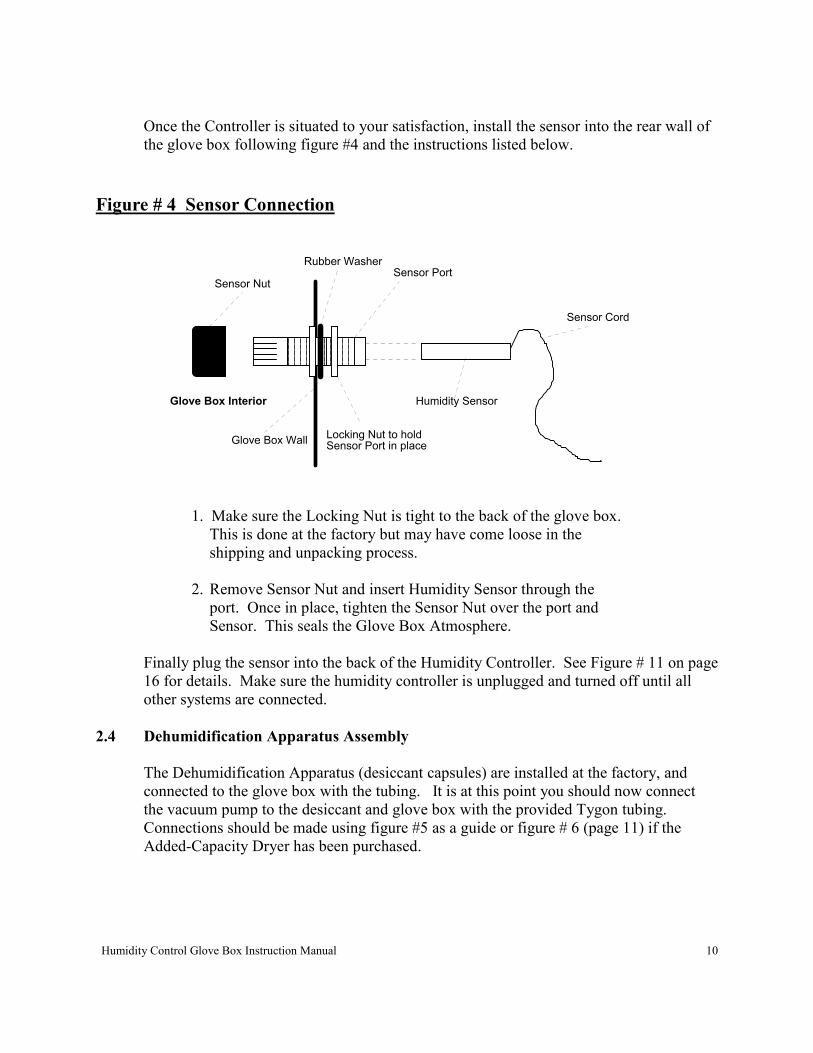
Once the Controller is situated to your satisfaction, install the sensor into the rear wall of
the glove box following figure #4 and the instructions listed below.
Figure # 4 Sensor Connection
Glove Box Wall
Sensor Cord
Humidity Sensor
Locking Nut to holdSensor Port in place
Sensor PortSensor Nut
Glove Box Interior
Rubber Washer
1. Make sure the Locking Nut is tight to the back of the glove box.
This is done at the factory but may have come loose in the
shipping and unpacking process.
2. Remove Sensor Nut and insert Humidity Sensor through the
port. Once in place, tighten the Sensor Nut over the port and
Sensor. This seals the Glove Box Atmosphere.
Finally plug the sensor into the back of the Humidity Controller. See Figure # 11 on page
16 for details. Make sure the humidity controller is unplugged and turned off until all
other systems are connected.
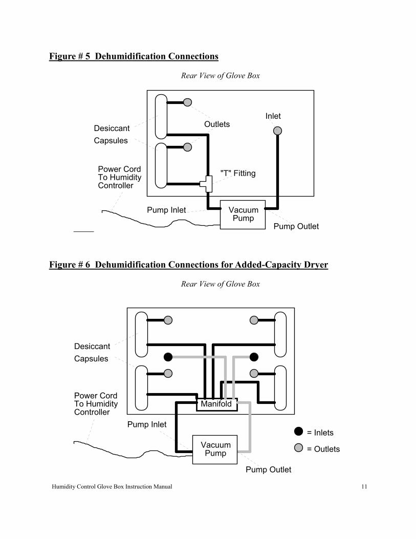
2.4 Dehumidification Apparatus Assembly
The Dehumidification Apparatus (desiccant capsules) are installed at the factory, and
connected to the glove box with the tubing. It is at this point you should now connect
the vacuum pump to the desiccant and glove box with the provided Tygon tubing.
Connections should be made using figure #5 as a guide or figure # 6 (page 11) if the
Added-Capacity Dryer has been purchased.
Humidity Control Glove Box Instruction Manual 11
Figure # 5 Dehumidification Connections
Rear View of Glove Box
Desiccant
Capsules
VacuumPump
OutletsInlet
"T" Fitting
Pump Inlet
Pump Outlet
To HumidityController
Power Cord
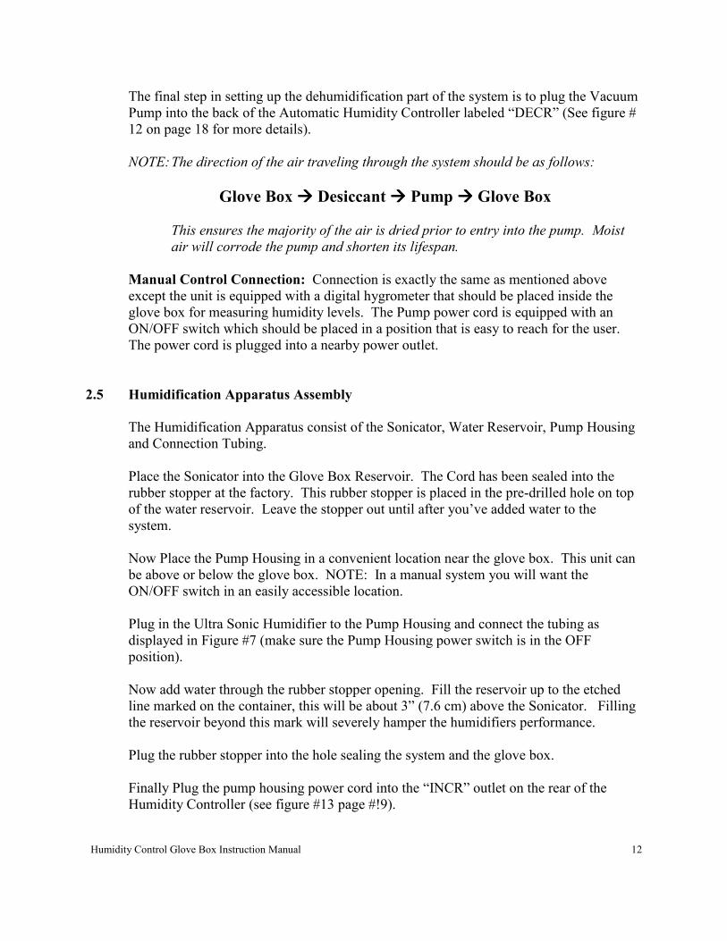
Figure # 6 Dehumidification Connections for Added-Capacity Dryer
Rear View of Glove Box
Desiccant
Capsules
Manifold
= Inlets
= OutletsVacuumPump
Pump Inlet
Pump Outlet
To HumidityController
Power Cord
Humidity Control Glove Box Instruction Manual 12
The final step in setting up the dehumidification part of the system is to plug the Vacuum
Pump into the back of the Automatic Humidity Controller labeled “DECR” (See figure #
12 on page 18 for more details).
NOTE: The direction of the air traveling through the system should be as follows:
Glove Box ���� Desiccant ���� Pump ���� Glove Box
This ensures the majority of the air is dried prior to entry into the pump. Moist
air will corrode the pump and shorten its lifespan.
Manual Control Connection: Connection is exactly the same as mentioned above
except the unit is equipped with a digital hygrometer that should be placed inside the
glove box for measuring humidity levels. The Pump power cord is equipped with an
ON/OFF switch which should be placed in a position that is easy to reach for the user.
The power cord is plugged into a nearby power outlet.
2.5 Humidification Apparatus Assembly
The Humidification Apparatus consist of the Sonicator, Water Reservoir, Pump Housing
and Connection Tubing.
Place the Sonicator into the Glove Box Reservoir. The Cord has been sealed into the
rubber stopper at the factory. This rubber stopper is placed in the pre-drilled hole on top
of the water reservoir. Leave the stopper out until after you’ve added water to the
system.
Now Place the Pump Housing in a convenient location near the glove box. This unit can
be above or below the glove box. NOTE: In a manual system you will want the
ON/OFF switch in an easily accessible location.
Plug in the Ultra Sonic Humidifier to the Pump Housing and connect the tubing as
displayed in Figure #7 (make sure the Pump Housing power switch is in the OFF
position).
Now add water through the rubber stopper opening. Fill the reservoir up to the etched
line marked on the container, this will be about 3” (7.6 cm) above the Sonicator. Filling
the reservoir beyond this mark will severely hamper the humidifiers performance.
Plug the rubber stopper into the hole sealing the system and the glove box.
Finally Plug the pump housing power cord into the “INCR” outlet on the rear of the
Humidity Controller (see figure #13 page #!9).
Humidity Control Glove Box Instruction Manual 13
Refilling the Water Reservoir in a Sealed Atmosphere
Some units will be used where the user does not want to compromise the glove box
atmosphere (clean or N2 environments for example). For these applications a Refill
Reservoir has been provided with tubing and a quick disconnect fitting.
To operate place the Refill Reservoir above the Water Reservoir, and fill with water.
Disconnect the tubing from the Pump Hosing Outlet and connect to the tubing from the
Refill Reservoir. Once connected the water will begin to flow into the Water Reservoir.
To stop the flow simply disconnect the tubing. Running the unit with water levels less
than ½” (1.27 cm) may damage the unit.
Glove box atmosphere is maintained as the quick disconnect tubing is self sealing when
disconnected.
NOTE: Distilled water will prolong equipment life but is not necessary for the operation
of the system.
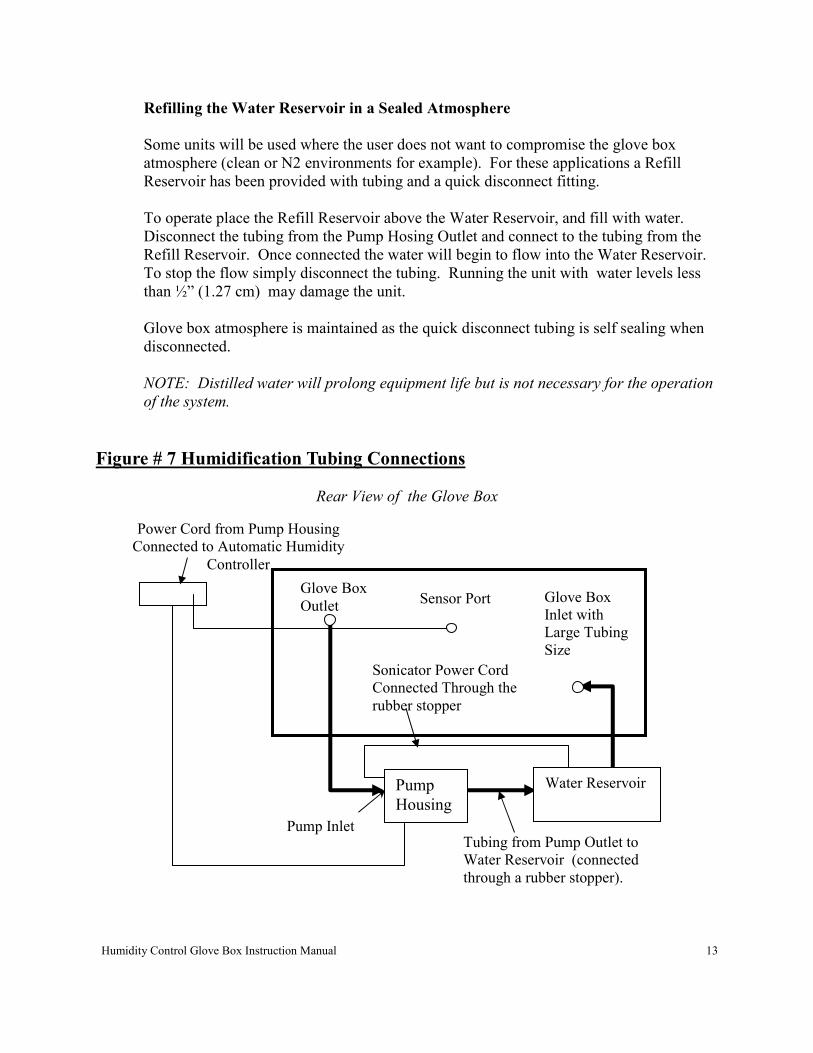
Figure # 7 Humidification Tubing Connections
Rear View of the Glove Box
Power Cord from Pump Housing
Connected to Automatic Humidity
Controller
Glove Box
Outlet
Pump Inlet
Sonicator Power Cord
Connected Through the
rubber stopper
Tubing from Pump Outlet to
Water Reservoir (connected
through a rubber stopper).
Pump
Housing
Glove Box
Inlet with
Large Tubing
Size
Water Reservoir
Sensor Port

Humidity Control Glove Box Instruction Manual 14
2.51 Humidification Apparatus Assembly for Heated Units ONLY.
Note: If you have purchased a glove box with heating options the placement of the Water
Reservoir is located inside the glove box for optimal efficiency at elevated temperatures.
Use the following instructions for set-up, operating instructions remain the same.
The Humidification Apparatus has had the Glove Box Water Reservoir installed from the
factory on the interior. All other items have to be installed and connected by the user.
Start by placing the Ultra Sonic Humidifier into the Glove Box Water Reservoir. The
cord has already been sealed in the rubber stopper which is placed in the pre-drilled hole
on the back of the glove box. Place the Sonic Humidifier in a corner of the water
reservoir, failure to do so could result in water splashing through the humidifier glove
box opening.
Next place the Pump Housing in a convenient location near the glove box. This unit can
be above or below the glove box. Plug the Ultra Sonic Humidifier to the Pump Housing,
and connect the tubing as displayed in Figure #8 and 9 (make sure the Pump Housing
power switch is in the OFF position. It is important to connect the inlet and outlet tubing
properly. The pump outlet has to connect to the Glove Box Water Reservoir.
Now the system is ready to have water added to it. For this operation place the Water
Refill Reservoir (clear box with quick disconnect fitting) above the Glove Box Reservoir.
Fill the Refill Reservoir with water then connect the tubing to the Glove Box Reservoir.
Once the quick disconnect fitting is connected the water will flow into the Glove Box
Reservoir. Fill the Glove Box Reservoir up to the bottom of the rubber stopper. To stop
the flow of water simply disconnect the tubing. A latch has been provided on the
reservoir to secure tubing when not in use.
NOTE: Distilled water will prolong equipment life but is not necessary for operation of
the system.
Humidity Control Glove Box Instruction Manual 15
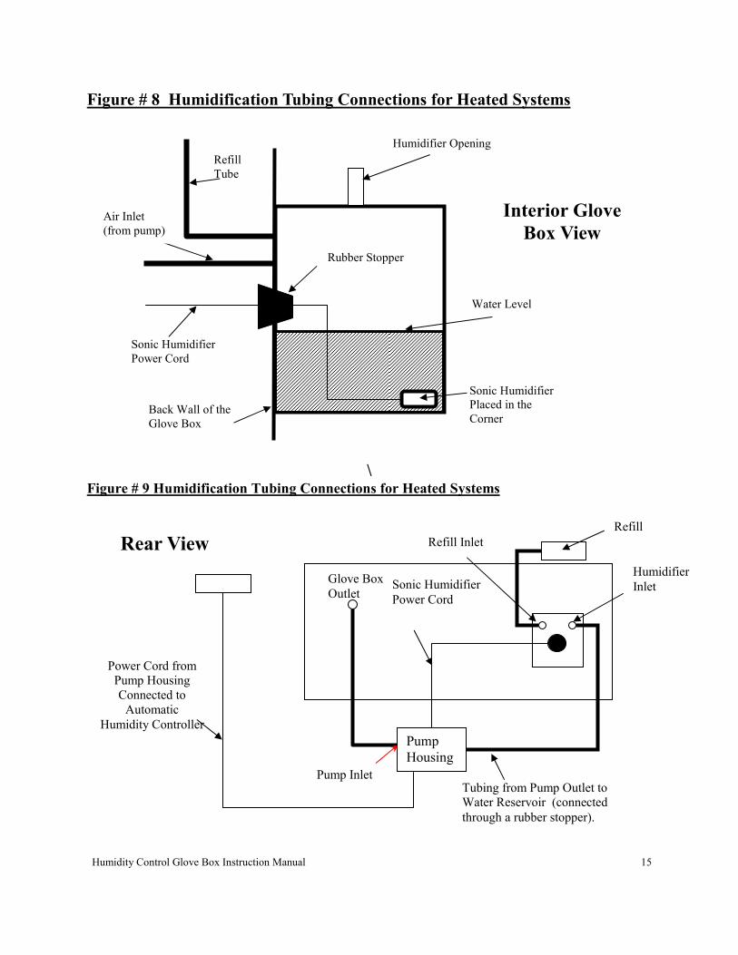
Figure # 8 Humidification Tubing Connections for Heated Systems
\
Figure # 9 Humidification Tubing Connections for Heated Systems
Power Cord from
Pump Housing
Connected to
Automatic
Humidity Controller
Glove Box
Outlet
Pump Inlet Tubing from Pump Outlet to
Water Reservoir (connected
through a rubber stopper).
Pump
Housing
Refill
Reservoi
Humidifier
Inlet Sonic Humidifier
Power Cord
Refill Inlet Rear View
Sonic Humidifier
Placed in the
Corner
Water Level
Back Wall of the
Glove Box
Rubber Stopper
Sonic Humidifier
Power Cord
Refill
Tube
Humidifier Opening
Interior Glove
Box View Air Inlet
(from pump)
Humidity Control Glove Box Instruction Manual 16
Manual Humidification Set Up: Exactly as stated above except unit includes Digital
Hygrometer to monitor humidity levels (% Rh). This should be placed inside so that it
can easily be monitored. The plug strip’s ON/OFF switch turns the humidification
system “ON” and “OFF” therefore this plug strip should be located within easy access for
the user.
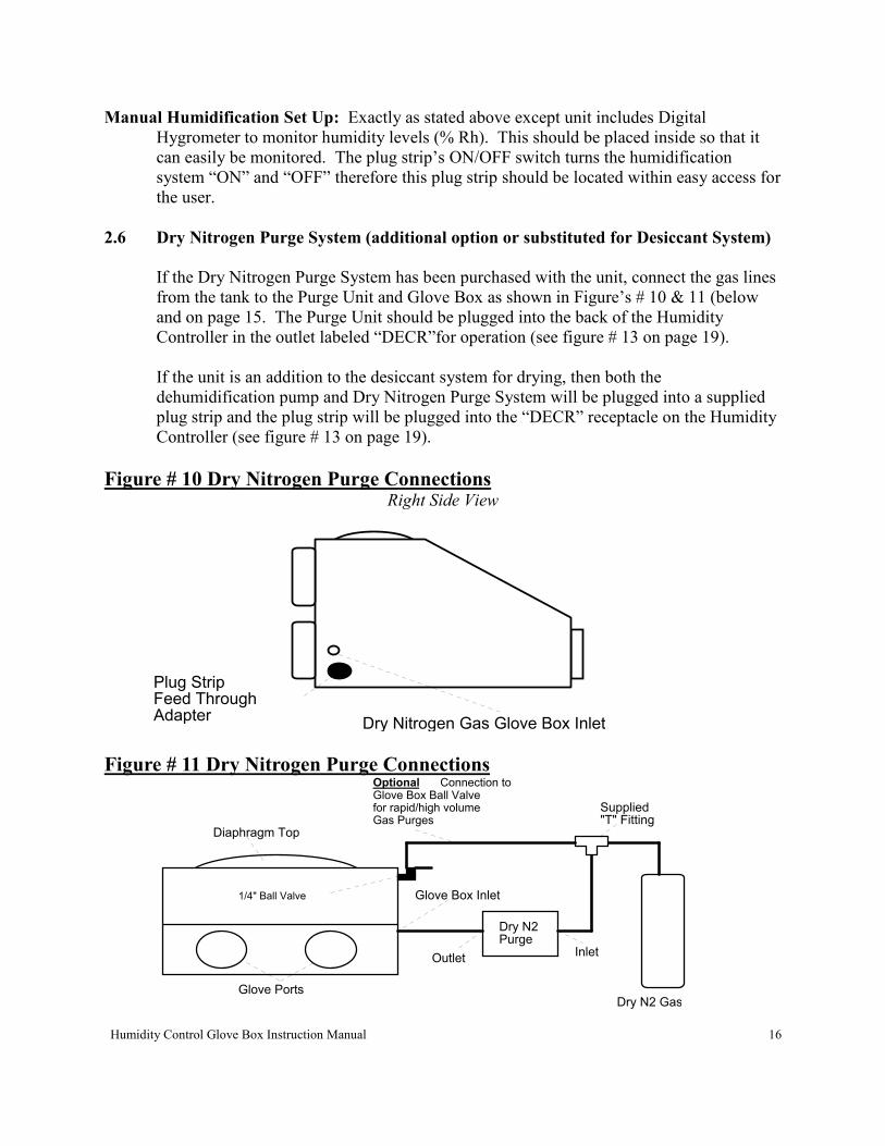
2.6 Dry Nitrogen Purge System (additional option or substituted for Desiccant System)
If the Dry Nitrogen Purge System has been purchased with the unit, connect the gas lines
from the tank to the Purge Unit and Glove Box as shown in Figure’s # 10 & 11 (below
and on page 15. The Purge Unit should be plugged into the back of the Humidity
Controller in the outlet labeled “DECR”for operation (see figure # 13 on page 19).
If the unit is an addition to the desiccant system for drying, then both the
dehumidification pump and Dry Nitrogen Purge System will be plugged into a supplied
plug strip and the plug strip will be plugged into the “DECR” receptacle on the Humidity
Controller (see figure # 13 on page 19).
Figure # 10 Dry Nitrogen Purge Connections Right Side View
Dry Nitrogen Gas Glove Box Inlet
Plug StripFeed ThroughAdapter
Figure # 11 Dry Nitrogen Purge Connections
1/4" Ball Valve
Diaphragm Top
Glove Ports
Dry N2 Purge
Supplied "T" Fitting
OptionalGlove Box Ball Valvefor rapid/high volume Gas Purges
Dry N2 Gas
InletOutlet
Glove Box Inlet
Connection to
Humidity Control Glove Box Instruction Manual 17
PID Heated Fan Set point
To adjust temperature press release the ups and down arrow keys in the direction you
desire. The temperature will increase or decrease by 0.1 C. Hold the arrow key and the
temperature will change at a faster rate. Release the button when you reached the proper
set point.
Calibration
Press and release the advance key until you come to CAL use the up or down keys to
calibrate.
Increasing this number will increase your process value.
** Warning
Do not change any other setting in the menu setting. Doing so could cause the
controller to malfunction.
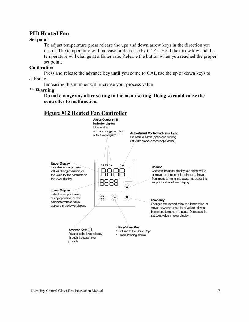
Figure #12 Heated Fan Controller
Infinity/Home Key:
* Returns to the Home Page
* Clears latching alarms.
Auto-Manual Control Indicator Light:
On: Manual Mode (open-loop control)
Off: Auto Mode (closed-loop Control)
Advance Key:
Advances the lower display
through the parameter
prompts
Upper Display:
Indicates actual process
values during operation, or
the value for the parameter in
the lower display.
Lower Display:
Indicates set point value
during operation, or the
parameter whose value
appears in the lower display.
321 %
Active Output (1-3)
Indicator Lights:
Lit when the
corresponding controller
output is energizes
Down Key:
Changes the upper display to a lower value, or
moves down through a list of values. Moves
from menu to menu in a page. Decreases the
set point value in lower display.
Up Key:
Changes the upper display to a higher value,
or moves up through a list of values. Moves
from menu to menu in a page. Increases the
set point value in lower display
Humidity Control Glove Box Instruction Manual 18
Operation of Components
3.1 Automatic Humidity Controller
Use Figures #13 & 14 as a reference
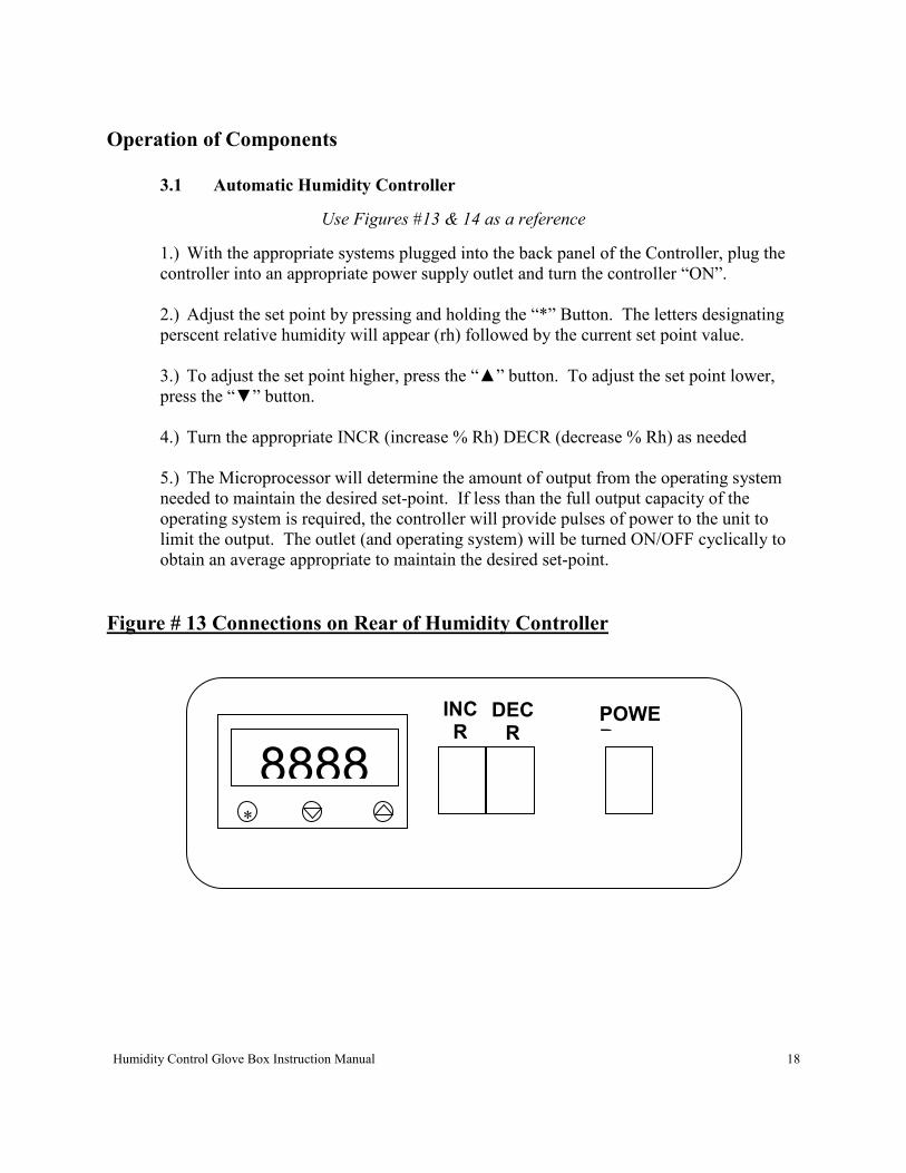
1.) With the appropriate systems plugged into the back panel of the Controller, plug the
controller into an appropriate power supply outlet and turn the controller “ON”.
2.) Adjust the set point by pressing and holding the “*” Button. The letters designating
perscent relative humidity will appear (rh) followed by the current set point value.
3.) To adjust the set point higher, press the “▲” button. To adjust the set point lower,
press the “▼” button.
4.) Turn the appropriate INCR (increase % Rh) DECR (decrease % Rh) as needed
5.) The Microprocessor will determine the amount of output from the operating system
needed to maintain the desired set-point. If less than the full output capacity of the
operating system is required, the controller will provide pulses of power to the unit to
limit the output. The outlet (and operating system) will be turned ON/OFF cyclically to
obtain an average appropriate to maintain the desired set-point.
Figure # 13 Connections on Rear of Humidity Controller
8888 *
INCR
DECR
POWER
Humidity Control Glove Box Instruction Manual 19
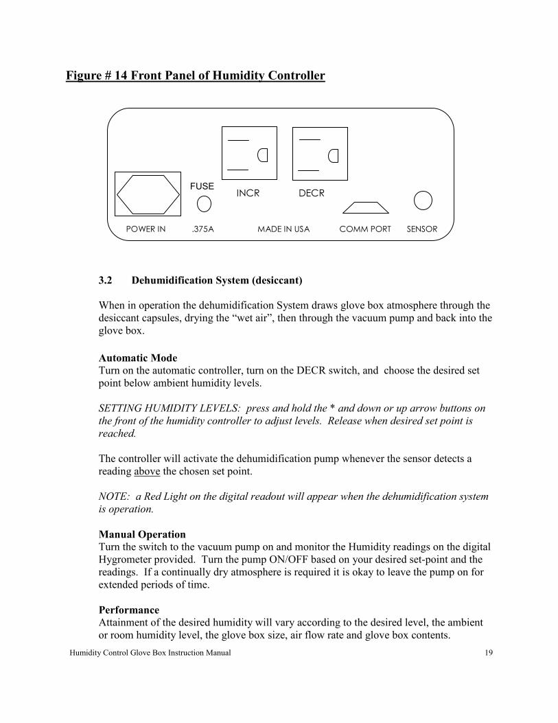
Figure # 14 Front Panel of Humidity Controller
3.2 Dehumidification System (desiccant)
When in operation the dehumidification System draws glove box atmosphere through the
desiccant capsules, drying the “wet air”, then through the vacuum pump and back into the
glove box.
Automatic Mode Turn on the automatic controller, turn on the DECR switch, and choose the desired set
point below ambient humidity levels.
SETTING HUMIDITY LEVELS: press and hold the * and down or up arrow buttons on
the front of the humidity controller to adjust levels. Release when desired set point is
reached.
The controller will activate the dehumidification pump whenever the sensor detects a
reading above the chosen set point.
NOTE: a Red Light on the digital readout will appear when the dehumidification system
is operation.
Manual Operation Turn the switch to the vacuum pump on and monitor the Humidity readings on the digital
Hygrometer provided. Turn the pump ON/OFF based on your desired set-point and the
readings. If a continually dry atmosphere is required it is okay to leave the pump on for
extended periods of time.
Performance Attainment of the desired humidity will vary according to the desired level, the ambient
or room humidity level, the glove box size, air flow rate and glove box contents.
POWER IN .375A MADE IN USA COMM PORT SENSOR
INCR DECR FUSE
Humidity Control Glove Box Instruction Manual 20
Frequency of door activity and room humidity levels will thereafter determine the
systems ability to maintain the desired level.
By way of reference, tests at the factory indicate the humidity level in a 3 ft. wide (10 cu.
ft.) Polymer Glove Box will drop from 70% Rh to <5% in approximately 1.5 hours. The
test glove box had 2 desiccant capsules and the pump was at its maximum flow rate of
1.25 cubic feet per hour (CFH).
HINT: To achieve optimum performance at low levels you may need to place a cuff
length glove on the gloveless sleeves.
Regeneration of Desiccant Indicating Desiccant displays the moisture saturation level by a color change (blue to
pink). To rejuvenate the desiccant, spread in thin layers on a pan or cookie sheet in an
oven and bake for 1-2 hours at 200° C. Allow desiccant to cool, and then return to
acrylic capsule.
3.3 Dehumidification System (dry N2 purge)
When in operation, the Dry Nitrogen Purge System pumps in the desired gas through the
installed distribution tube. The dry air pushes out moist air in the glove box through the
pressure relief valve.
SETTING HUMIDITY LEVELS: press and hold the * and down or up arrow buttons on
the front of the humidity controller to adjust levels. Release when desired set point is
reached.
To operate, turn “ON” the Dry Gas Purge unit, turn “ON” the DECR switch and then
choose a desired set point. The controller will purge gas in automatically based on the
chosen set point and the measured humidity readings.
The controller will activate the Dry Gas Purge whenever the sensor detects a reading
above the chosen set point.
NOTE: a Red Light on the digital readout will appear when the dehumidification system
is operation.
Performance Attainment of the desired humidity will vary according to the desired level, moisture
content of gas being purged into the glove box, the ambient or room humidity level, the
glove box size, air flow rate and glove box contents. Frequency of door activity and
room humidity levels will thereafter determine the systems ability to maintain the desired
level.
Humidity Control Glove Box Instruction Manual 21
Test Data: 5 ft. Glove Box (25 cubic ft.) was used for the test at the factory with the
nitrogen gas regulator set at 15 psi and the Dry N2 Purge System set at 100 scfh. From
71% Rh to 12% Rh took 54 minutes, and used 1025 psi of gas.
3.4 Humidification System
If you have the Manual Control Version, plug the Pump Housing into an appropriate
power outlet. Use the Pump Housing Switch to manually control the operation of the
Pump and Sonic Humidifier. If you have the automatic system, plug the Pump Housing
into the rear of the Controller. In both cases the inline Pump switch must be “ON”.
Automatic Mode: Turn on the automatic controller, turn on the INCR switch, and
choose the desired set point above ambient humidity levels.
SETTING HUMIDITY LEVELS: press and hold the * and down or up arrow buttons on
the front of the humidity controller to adjust levels. Release when desired set point is
reached.
The controller will activate the humidification pump whenever the sensor detects a
reading below the chosen set point.
NOTE: a Green Light on the digital readout will appear when the dehumidification
system is operation..
Manual Mode: Exactly as above except monitoring is done with the digital Hygrometer
and Pump Housing is plugged into a suitable power supply.
Sonic Humidifier Care & Warnings:
� Be careful of the water level sensor switch, do not grab/hold this to lift the unit up or scratch/drop it, doing so can damage the sensor
� Do not move the unit or handle the cable when in operation. Do not place your finger on the ceramic disc while in operation as the vibration will hurt but is not an electric
shock.
� Do not operate the humidifier when there is not enough water in the reservoir or dry. This will cause the sonicator to not function correctly and will shorten it’s life. For
proper operating never let the water levels drop below 1/2 “ above the sonicator
Sonic Humidifier Maintenance & Service:
� Clean the ceramic disc and the surface of the mister with a soft cloth in clean water.
Humidity Control Glove Box Instruction Manual 22
Do not use abrasive cleaners to clean any part of the Sonic Humidifier.
� If the unit can not generate mist after running for a long time, check water levels in the Water Reservoir. If the LED lamp is also off, check the power connection.
� If the unit can not generate mist, but only water spray then the Sonic Humidifier is good but the water is dirty and needs to be replaced. To do this remove the rubber
stopper on the Reservoir and tilt the glove box back until the old water drains out of
the opening. Replace the Sonic Humidifier and refill with fresh water.
� After running for approximately 3000 hours the mist generated will be noticeably reduced, this is an indication that a new ceramic disc is needed. Please contact COY
Labs for part number and current pricing.
4.0 Care and Cleaning
4.1 Care and Cleaning (Dehumidification System)
Periodically the Desiccant will need to be rejuvenated. This can be done by pouring the
desiccant out of the capsule and placing it in an oven to dry. The drying time is 1-2 hours
at 200° C. Allow the desiccant to cool completely prior to returning it to the acrylic
capsules. Desiccant should be replaced once a year based on average use.
4.2 Care and Cleaning (Humidifier)
The Humidifier must be cleaned regularly to maintain peak performance. Ordinary tap
water contains many minerals and chemical which can leave deposits and affect the
absorbency of the wick. COY recommends using only distilled water because of this.
When cleaning is necessary, unplug the electrical cord and carefully remove the Fan
Assembly from the black rubber Feed Thru adaptor. With a soft cloth and vinegar, wipe
the whole assembly to remove any dirt and mineral deposits. Thoroughly rinse with
clean water and allow drying before reconnecting electrical power.
Do not clean any part of the system with solvents or with water hotter than 100° C. If
you do not intend to use the system for an extended time, empty all water from the
system and clean with vinegar. This will help prevent a buildup of mineral deposits and
bacterial growth.
Humidity Control Glove Box Instruction Manual 23
4.3 Care and Cleaning of the Glove Box
Care of Polycarbonate material There are several precautions you can take to prolong the life of your glove box.
Precautions you should carefully follow are:
1. Do not use abrasive cleaners at any time on the Polycarbonate portions of the glove
box
2. Do not use any solvent like liquids to clean the plastic. Isopropyl alcohol is
acceptable as well as a mild bleach solution (5-10%).
3. Keep equipment and shelving units within easy reach so you do not stretch the
chamber sleeves.
4. Rings and jewelry should be removed prior to using the glove box so as the
polycarbonate is not scratched or the sleeves and gloves are not torn. Finger nails
should also be clipped short.
5. Protect the glove box from organic solvent fumes and nearby painting and plastering.
If splashed, wipe immediately while wet with a soft cloth.
Cleaning the Polycarbonate
Dust and clean with a soft cloth or chamois having first sprayed on a plastic cleaner.
(COY part no. 1600-480) The use of a mild soap or detergent and plenty of water is
good. Dry with a soft cloth or chamois.
Minor scratches can be removed by hand polishing. Polishes are best applied with a soft
cloth dampened with water first. Several applications may be necessary, but most minor
scratches can be reduced and the clarity improved in a short time.
4.4 Care of Sleeves and Gloves
The arm length gloves are made of neoprene rubber and are susceptible to
punctures and tears. Wear cotton gloves when working with sharp objects. Remove
jewelry. If a hole is punctured in the glove, it must be replaced. Do not use the glove
box until the damaged gloves have been replaced.
Gloveless Sleeves are standard with the Humidity Control Glove Box but Sleeve
Length Gloves may be substituted for these.
The arm length gloves and gloveless sleeves are made of neoprene rubber and are
susceptible to punctures and tears. Wear cotton gloves when working with sharp objects.
Humidity Control Glove Box Instruction Manual 24
Remove jewelry. If a hole is punctured in the glove/sleeve, it must be replaced. Do not
use the glove box until the damaged gloves have been replaced.
Butyl and Hypalon Gloves are also available.
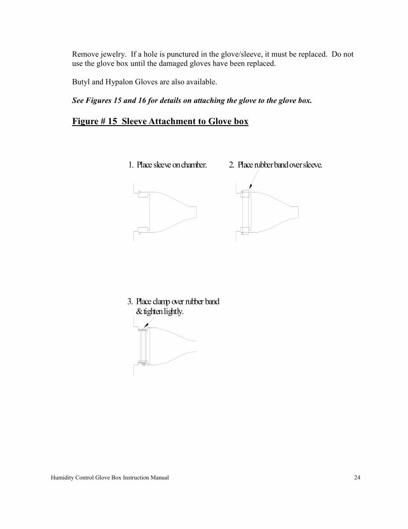
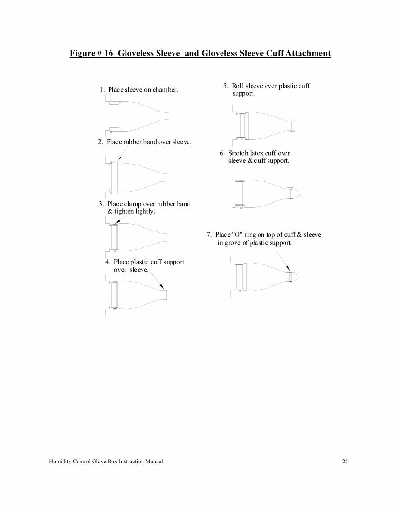
See Figures 15 and 16 for details on attaching the glove to the glove box.
Figure # 15 Sleeve Attachment to Glove box
1. Place sleeve on chamber. 2. Place rubber band over sleeve.
3. Place clamp over rubber band & tighten lightly.
Humidity Control Glove Box Instruction Manual 25
Figure # 16 Gloveless Sleeve and Gloveless Sleeve Cuff Attachment
1. Place sleeve on chamber.
2. Place rubber band over sleeve.
3. Place clamp over rubber band & tighten lightly.
4. Place plastic cuff support over sleeve.
5. Roll sleeve over plastic cuff support.
6. Stretch latex cuff over sleeve & cuff support.
7. Place "O" ring on top of cuff & sleeve in grove of plastic support.
Humidity Control Glove Box Instruction Manual 26
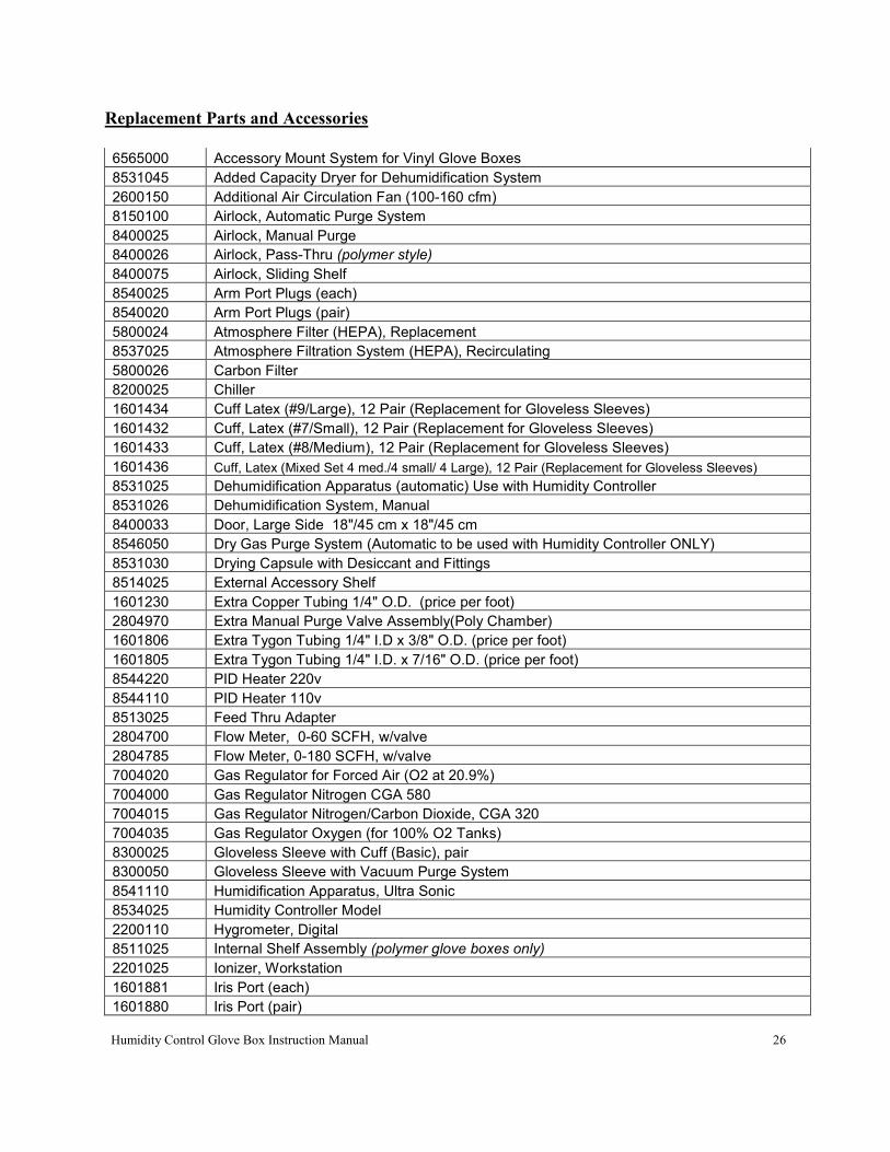
Replacement Parts and Accessories
6565000 Accessory Mount System for Vinyl Glove Boxes
8531045 Added Capacity Dryer for Dehumidification System
2600150 Additional Air Circulation Fan (100-160 cfm)
8150100 Airlock, Automatic Purge System
8400025 Airlock, Manual Purge
8400026 Airlock, Pass-Thru (polymer style)
8400075 Airlock, Sliding Shelf
8540025 Arm Port Plugs (each)
8540020 Arm Port Plugs (pair)
5800024 Atmosphere Filter (HEPA), Replacement
8537025 Atmosphere Filtration System (HEPA), Recirculating
5800026 Carbon Filter
8200025 Chiller
1601434 Cuff Latex (#9/Large), 12 Pair (Replacement for Gloveless Sleeves)
1601432 Cuff, Latex (#7/Small), 12 Pair (Replacement for Gloveless Sleeves)
1601433 Cuff, Latex (#8/Medium), 12 Pair (Replacement for Gloveless Sleeves)
1601436 Cuff, Latex (Mixed Set 4 med./4 small/ 4 Large), 12 Pair (Replacement for Gloveless Sleeves)
8531025 Dehumidification Apparatus (automatic) Use with Humidity Controller
8531026 Dehumidification System, Manual
8400033 Door, Large Side 18"/45 cm x 18"/45 cm
8546050 Dry Gas Purge System (Automatic to be used with Humidity Controller ONLY)
8531030 Drying Capsule with Desiccant and Fittings
8514025 External Accessory Shelf
1601230 Extra Copper Tubing 1/4" O.D. (price per foot)
2804970 Extra Manual Purge Valve Assembly(Poly Chamber)
1601806 Extra Tygon Tubing 1/4" I.D x 3/8" O.D. (price per foot)
1601805 Extra Tygon Tubing 1/4" I.D. x 7/16" O.D. (price per foot)
8544220 PID Heater 220v
8544110 PID Heater 110v
8513025 Feed Thru Adapter
2804700 Flow Meter, 0-60 SCFH, w/valve
2804785 Flow Meter, 0-180 SCFH, w/valve
7004020 Gas Regulator for Forced Air (O2 at 20.9%)
7004000 Gas Regulator Nitrogen CGA 580
7004015 Gas Regulator Nitrogen/Carbon Dioxide, CGA 320
7004035 Gas Regulator Oxygen (for 100% O2 Tanks)
8300025 Gloveless Sleeve with Cuff (Basic), pair
8300050 Gloveless Sleeve with Vacuum Purge System
8541110 Humidification Apparatus, Ultra Sonic
8534025 Humidity Controller Model
2200110 Hygrometer, Digital
8511025 Internal Shelf Assembly (polymer glove boxes only)
2201025 Ionizer, Workstation
1601881 Iris Port (each)
1601880 Iris Port (pair)
Recommended