Embed Size (px)
Citation preview
Model Programming Choices
1F95-1291 7 Day 5/1/1 Day Non-Programmable
www.white-rodgers.com
Big Blue Humidity Universal Thermostat with Humidity/Dehumidity Control and
Automatic Heat/Cool Changeover Option
PART NO. 37-6914DReplaces 37-6914C
0905
Single Stage, Multi-Stage, Heat PumpInstallation and Operating Instructions
APPLICATIONS1F95-1291 Humidity Control Touchscreen Thermostat
SPECIFICATIONS
Save these instructions for future use!
FAILURE TO READ AND FOLLOW ALL INSTRUCTIONS CAREFULLY BEFORE INSTALLING OR OPERATING THIS CONTROL COULD CAUSE PERSONAL INJURY AND/OR PROPERTY DAMAGE.
THERMOSTAT APPLICATION GUIDE
Thermostat Confi guration Options
Thermostat Applications
Maximum Stages
Heat/Cool
Single Stage 1No Heat Pump (SS1)
Gas, Oil, Electric, Heat Only, Cool Only or Heat/Cool
Systems, 2 or 3 wire Hydronic Zone (Hot Water or Steam) Systems, 24 Volt or Millivolt
1/1
Multi Stage 2No Heat Pump (MS2) 2/2
Heat Pump 1Single Stage Compressor
Heat Pump (HP1)
Single Stage Compressor Heat Pump Systems - up to 2 Stages Aux./Emergency Heat
3/1
Heat Pump 2Two Stage or Two
Compressor Heat Pump (HP2)
Two Stage or Two Compressor Heat Pump systems - up to 2 Stages Aux./Emergency Heat
4/2
ATTENTION: MERCURY NOTICEThis product does not contain mercury. However, this prod-uct may replace a product that contains mercury.
Mercury and products containing mercury must not be discarded in household trash. Do not touch any spilled mercury. Wearing non-absorbent gloves, clean up any spilled mercury and place in a sealed container. For proper disposal of a product containing mercury or a sealed container of spilled mercury, place it in a suitable shipping container. Refer to www.white-rodgers.com for location to send the product containing mercury.
Index PageInstallation 2Wiring Diagrams 3Thermostat Quick Reference 5Installer Confi guration Menu 6Operating Your Thermostat 10Programming 12Troubleshooting 16
Electrical Rating: Battery Power . . . . . . . . . . . . . . . . . . . . . . . . . . mV to 30 VAC, NEC Class II, 50/60 Hz or DC Input-Hardwire . . . . . . . . . . . . . . . . . . . . . . . . . 20 to 30 VACTerminal Load . . . . . . . . . . . . . . . . . . . . . . . . . . . . . 1.5A per terminal, 2.5A maximum all terminals combinedSetpoint Range . . . . . . . . . . . . . . . . . . . . . . . . . . . . 45 to 99°F (7 to 32°C)Differential (Single Stage) . . . . . . . . . . . . . . . . . . . . Heat 0.6°F; Cool 1.2°FDifferential (Multi-Stage) . . . . . . . . . . . . . . . . . . . . . Heat 0.6°F; Cool 1.2°FDifferential (Heat Pump) . . . . . . . . . . . . . . . . . . . . . Heat 1.2°F; Cool 1.5°FOperating Ambient. . . . . . . . . . . . . . . . . . . . . . . . . . 32°F to +105°F (0 to +41°C)Operating Humidity . . . . . . . . . . . . . . . . . . . . . . . . . 90% non-condensing max.Shipping Temperature Range . . . . . . . . . . . . . . . . . -40 to +150°F (-40 to +65°C)Dimensions Thermostat. . . . . . . . . . . . . . . . . . . . . . 4.6"H x 5.9"W x 1.2"D
To prevent electrical shock and/or equipment damage, disconnect electric power to system at main fuse or circuit breaker box until installation is complete.
CAUTION!
2
Remove Old ThermostatBefore removing wires from old thermostat, mark wires for terminal identifi cation so the proper connections will be made to the new thermostat.
Installing New Thermostat1. Pull the thermostat body off the thermostat base. Forcing
or prying on the thermostat will cause damage to the unit.
2. Place base over hole in wall and mark mounting hole locations on wall using base as a template.
3. Move base out of the way. Drill mounting holes. If you are using existing mounting holes and the holes drilled are too large and do not allow you to tighten base snugly, use plastic screw anchors to secure the base.
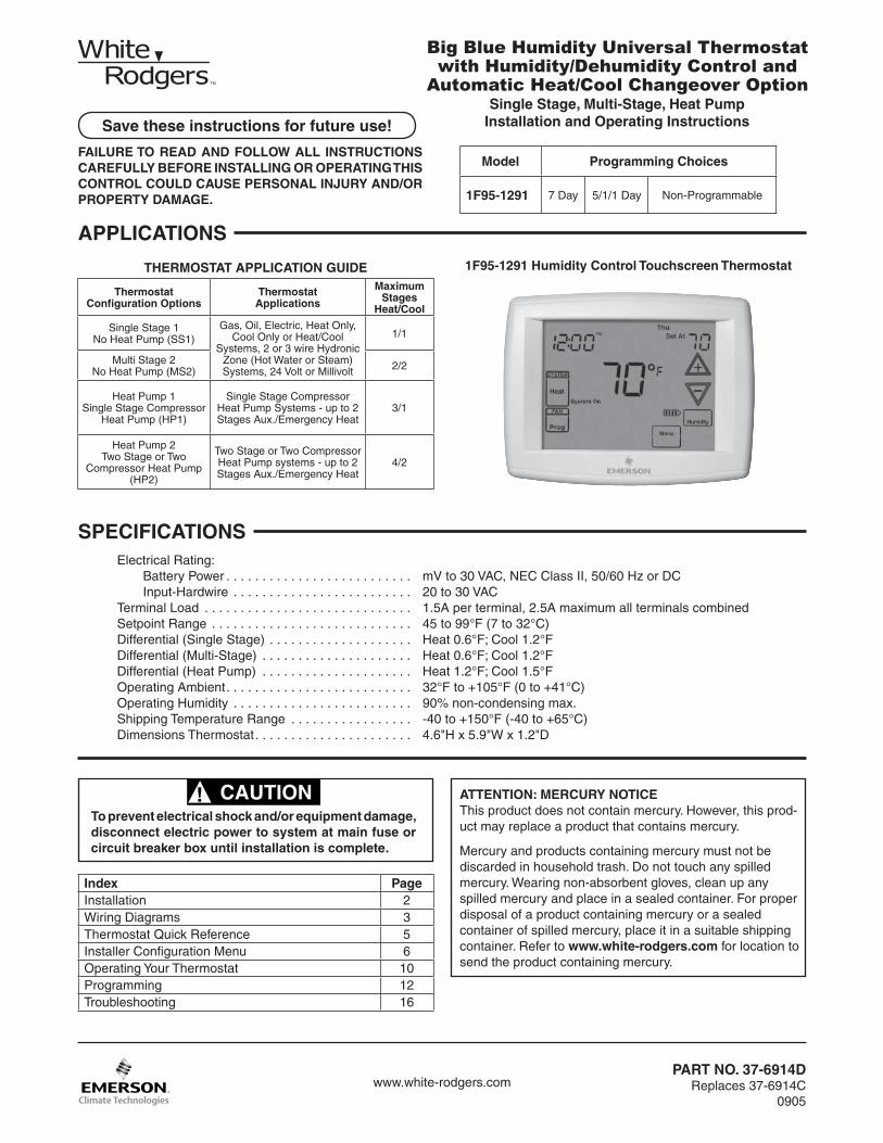
4. Fasten base snugly to wall using mounting holes shown in Figure 1 and two mounting screws. Leveling is for appearance only and will not affect thermostat operation.
5. Connect wires to terminal block on base using appropriate wiring schematic.
6. Push excess wire into wall and plug hole with a fi re resis-tant material (such as fi berglass insulation) to prevent drafts from affecting thermostat operation.
7. Carefully line the thermostat up with the base and snap into place.
Battery Location2 "AA" alkaline batteries are included in the thermostat at the factory with a battery tag to prevent power drainage. Remove the battery tag to engage the batteries.To replace batteries, set system to OFF, remove thermostat from wall and install the batteries in the rear along the top of the thermostat (see Figure 1). For best results, use a premi-um brand "AA" alkaline battery such as Duracell® or Ener-gizer®. If the home is going to be unoccupied for an extended period (over 3 months) and is displayed, the batteries should be replaced before leaving.
Power Stealing SwitchesThe Power Stealing Switches (Fig. 1) should be left in the "On" position for most systems. The information in the following table details the thermostat power method and switch options.
WARNING!Thermostat installation and all components of the control system shall conform to Class II circuits per the NEC code.
INSTALLATION
Figure 1 – Thermostat Base Multi-Stage 1F95-1291
2 "AA" Batteries
Power Stealing Switches
Stack PowerStealing Switch
MountingHole
MountingHole
Place Levelacross Mounting Tabs(for appearance only)
Place Levelacross Mounting Tabs (for appearance only)
+
S
HM
-
W/E
6
DHM
Y2
O/BL
YW2
Rear view of thermostat
Thermostat Power Method Switch Position/Description
Battery Powered, no 24 Volt system power available.
Switches "On", thermostat runs on batteries.
Hardwired with Battery Back-up, for 24 Volt systems with common connection from transformer to "C" terminal on thermostat.
Switches "On", thermostat runs on power directly from transformer with battery back-up.
*Battery Powered with Power Stealing Assist, for 24 Volt systems with no common connection from transformer to "C" terminal on thermostat.
Switches "On", thermostat runs on batteries and supplemental power drawn through the heat or cool circuit.
*Power Stealing Assist is very reliable to increase battery life, but on a small number of heating or cooling systems with high impedance electronic modules you may observe one of the following conditions:
1. The furnace draft inducer motor may run with no call for heat.
2. The furnace fan may turn on with no call for heat or may not turn off.
3. The furnace may not turn off when the call for heat ends.
4. The air conditioner may not turn off when the call for cool ends.
If the Power Stealing Assist method is not compatible with your system, place the Power Stealing Switches to "Off". This cancels Power Stealing Assist, operates the thermostat on batteries and corrects the condition.
3
WIRING DIAGRAMS
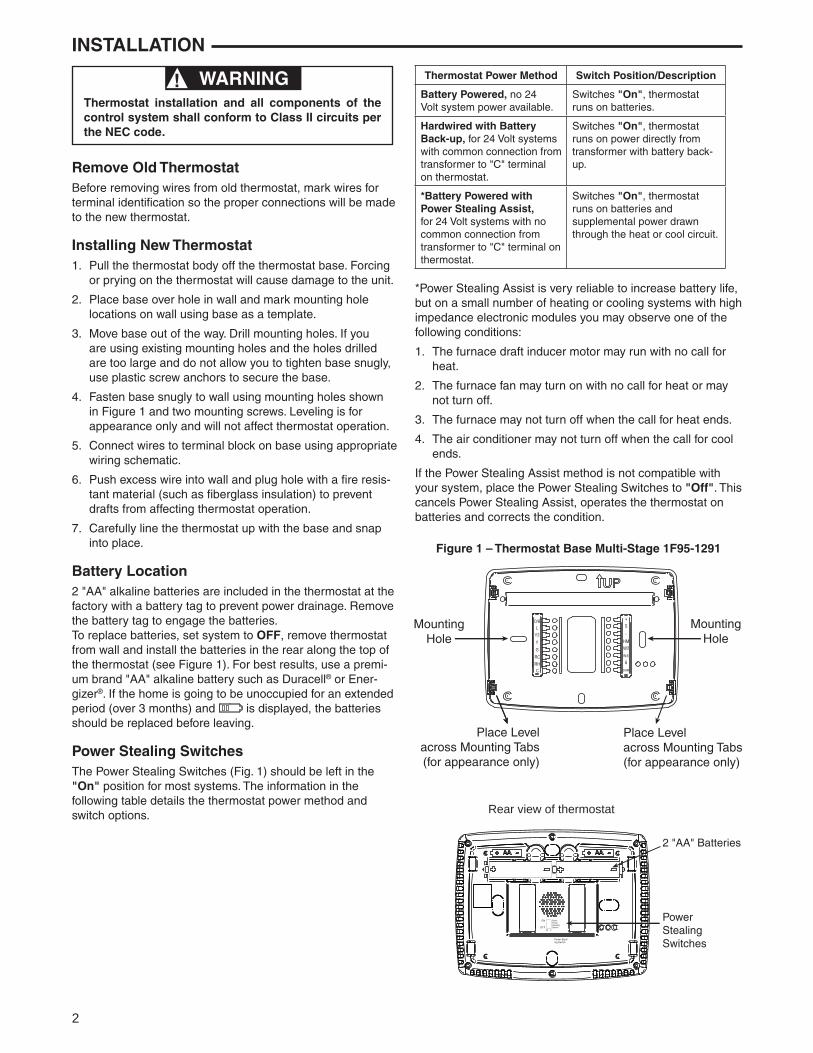
Figure 2 – Single Stage or Multi-Stage System(No Heat Pump) with Single Transformer
Single Stage 1(SS1)
Multi Stage 2(MS2)
System RC RH C Y Y2 W/E W2 G O/B 6 L
CLASS IITRANSFORMER
HOT
24VAC
NEUTRAL
120VAC
Call for heat
Heat mode-1ststage
Heat mode-2ndstage
No output
24 volt power for cooling
24 volt power for heating
Cool mode-2ndstage
24 volt common (optional
for system operation, required
for remote sensor)
Call for cool No Output
Cool mode-1ststage
Blower/Circulator fanenergized on a call for cool or Fan On(also energized in
heating if configuredfor Electric Heat)
InstallerConfigurationMenu selects “O” or “B” for changeoverfunction. Set
to “O” terminalenergized in Cool& Off mode. Set to “B” terminalenergized in
Heat & mergency mode
Power closedconnection forSPDT 3-wirezone valve
Fault or SystemMalfunctionIndicator for Heat Pumps
with “L” terminalconnection.
Original production 1F95-1291’s
do not have this connection
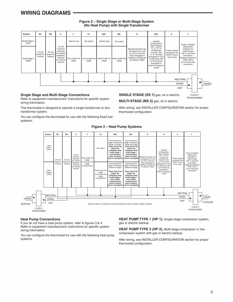
Figure 3 – Heat Pump Systems
Heat Pump ConnectionsIf you do not have a heat pump system, refer to fi gures 3 & 4.Refer to equipment manufacturers’ instructions for specifi c system wiring information.
You can confi gure the thermostat for use with the following heat pump systems.
Single Stage and Multi-Stage ConnectionsRefer to equipment manufacturers’ instructions for specifi c system wiring information.
This thermostat is designed to operate a single-transformer or two-transformer system.
You can confi gure the thermostat for use with the following fossil fuel systems:
HeatPump 1(HP1)
Heat Pump 2(HP2)
System RC RH C Y Y2 *W/E *W2 G O 6 L
CLASS IITRANSFORMER
HOT
24VAC
NEUTRAL
120VAC
Heat mode-2ndstage, Emergency
Mode-1st stage*Note: Dual Fuel
option de-energizes Heatmode stage 1(compressor)when auxiliary
heat is energized
Heat mode-3rdstage, Emergency
Mode-1st stage
*Note: Dual Fueloption de-
energizes Heatmode stages 1
and 2 (bothcompressors)when auxiliary
heat is energized
Heat mode-4thstage, EmergencyMode-2nd stage
*Note: Dual Fueloption de-
energizes Heatmode stages 1
and 2 (bothcompressors)when auxiliary
heat is energized
Heat mode-3rdstage, EmergencyMode-2nd stage*Note: Dual Fuel
option de-energizes Heatmode stage 1(compressor)when auxiliary
heat is energized24 volt
power for cooling
24 volt power for heating
Heat mode-2nd stage,
Cool mode-2nd stage,
(Compressor)
No Output
24 volt common (optional
for system operation, required
for remote sensor)
Heat mode-1ststage,
Cool mode-1ststage,
(Compressor)
Blower/Circulator fanenergized on a call for cool or Fan On(also energized in
heating if configuredfor Electric Heat)
InstallerConfigurationMenu selects “O” or “B” for changeoverfunction. Set
to “O” terminalenergized in Cool& Off mode. Set to “B” terminalenergized in
Heat & mergency mode
Power closedconnection forSPDT 3-wirezone valve
Fault or SystemMalfunctionIndicator for Heat Pumps
with “L” terminalconnection.
Original production 1F95-1291’s
do not have this connection
COOLING
CLASS IITRANSFORMER
HOT
24VAC
NEUTRAL
120VAC
HEATING
120VAC
*Dual fuel option, if selected turns off compressor(s) when Auxiliary stages energize.
SINGLE STAGE (SS 1) gas, oil or electric.
MULTI-STAGE (MS 2) gas, oil or electric.
After wiring, see INSTALLER CONFIGURATION section for proper thermostat confi guration.
HEAT PUMP TYPE 1 (HP 1). Single stage compressor system; gas or electric backup.
HEAT PUMP TYPE 2 (HP 2). Multi-stage compressor or two compressor system with gas or electric backup.
After wiring, see INSTALLER CONFIGURATION section for proper thermostat confi guration.

4
If you have a single stage compressor system see the dia-gram below. A relay (customer provided) should be installed as shown in Fig 7 to switch the fan speed to the next lower speed on a call for dehumidifi cation from the thermostat. The reduction in air fl ow allows the coil to remove more humidity from the air. The relay should be rated for blower motor load. Since this confi guration reduces the air fl ow in cooling, the
WIRING DIAGRAMS
anti-freeze-up control (White-Rodgers CAFC) or equivalent is recommended. The CAFC prevents the air conditioning coil from freezing due to low air fl ow, dirty fi lters, low refrigerant pressure, etc. The CAFC snaps onto the suction line close to the evaporator coil as possible and breaks the compressor circuit when the suction line drops below 38 °F and re-make the circuit at 46°F.
HOT
NEUTRAL 120 VAC
24 VAC
Relay90-290Qor equivalent
HOT
NEUTRAL 120 VAC
TRANSFORMER
RHM
Humidifier System
Figure 6 – Typical Wiring for 120V Humidifi er System
HOT
NEUTRAL 120 VAC
TRANSFORMER
HM
24 VAC
Humidifier System
R
Figure 7 – Typical Wiring for 24V Humidifi er System
Dehumidifi cation wiring without an electronically controlled variable speed blower system for single stage compressor system only.
HM DHM
Humidification Terminal, Energizes on call for
heat if Humidity setpoint is above room humidity.
Can also be used to provide humidification
independent of a call for heat and/or in cooling
mode if Automatic Humidification is
selected in Configura-tion Menu item #34
De-energizes on call for Dehumidification to lower the fan speed. The DHM terminal is only used on systems
with a compatible dehumidification feature that have the required terminal connection on the contol module or
have a relay installed to lower the fan speed
+ S -
Supply voltage to remote
temperaturesensor
Remote temperature sensor signal
Supply voltage to remote
temperaturesensor
Figure 4 – Humidity and Sensors
Relay 90-293Q or equivalent
No
NC
“Heat Fan Output”
N
DehumSpeed Fan
Med
DHM
N
Low
Normal High
“Cool Fan Output”
1
2
Normal Cool speed position (DHM energized)
Dehum speed mode (DHM de-energized)
1
2
Figure 5 – Typical Wiring for Dehumidifi er System

5
Programming and Confi guration Items
1 Displays and "Keypad Lockout" when in keypadlockout mode.Displays and "Temperature Limit" and "KeypadLockout" when limited range is activated and locked.Displays only "Temperature Limit" when limited rangeis activated.
2 Indicates period of day being programmed.
3 RUN SCHEDULE (run program) key.
4 SET TIME key or HOLD temperature key.
5 Displays "Change Filter"/"Change Pad"/"Change UV Lamp" when the system has run for the programmed fi lter/humidity pad/UV lamp time period as a reminder to change or clean your fi lter/humidity pad or to replace UV lamp.
6 COPY key or INSTALLER CONFIG key.
7 CLEAN DISPLAY key allows 30 seconds to wipe offthe display or ADVANCE DAY key for programming.
8 Used in programming to set time and in confi gurationmenu to change selections.
9 "Hold Until" indicates the time when a temporary holdperiod will end.
10 "Hours" and "Days" displays during steps in installerconfi guration.
11 The words "Hold At" are displayed when the thermostat is in the HOLD mode. "Temporary Hold At" is displayed when the thermostat is in a temporary HOLD mode.
12 "Humidity" indicates that the "Set At" display is Hu-midity setpoint.
13 "System On" indicates when heating or cooling stage is energized. "+2" indicates when a second stage is energized.
14 "Copy" indicates the copy program feature is beingused during programming.
Figure 9 – Programming & Confi guration Items
7
15
6 5
1 2 3 4 5 6 7 8 9 10
11
12
13
14
15
16
17
18
19
20
21
22
23
24
25
26
27
28
29
30
31
32
33
34
35
36
37
38
39
3
20
2
1
11 121016 17
9
8
18
14
13
419
15 A steady "Cool Savings" display indicates the featureis enabled in the installer menu. A fl ashing "CoolSavings" display indicates the feature is active.
16 "Remote" indicates that the indoor remote temperaturesensor, is being accessed. "Outdoor Remote" indi-cates the outdoor remote temperature sensor is beingaccessed.
17 Display time, remote temperature or humidity.
18 "Heat Pump" displays when the system confi guration is set in HP1/HP2.
19 "Call for Service" indicates a fault in the heating/cooling
systems. It does not indicate a fault in the thermostat.
20 Auto Schedule key for Auto Schedule function or Humidity key to display current Humidity and Humidity setpoint.
THERMOSTAT QUICK REFERENCEHome Screen Description
Time of Day
Day of WeekRoomTemperature
SystemSwitch
FanSwitch
Indicates whenthermostat is callingfor Heat or Cool
Battery Level IndicatorIndicating the current power levelof the 2 “AA” batteries. Full power remaining. Half power remaining.Change The batteries should be replaced at this time.
Menu key for enteringdifferent modes such asCleaning, Configuration, SetTime and Set Schedule
Press to view Humidity setpoint
TemperatureUP/Down used formodifying setpointas well as tonavigating the menus
Set Temperature/Humidity
Note: If is displayed, thethermostat is battery powered.When battery power remainingis approximately half, willbe displayed. If the home isgoing to be unoccupied for anextended period (over 3 months)and is displayed, the batteriesshould be replaced before leaving.
Figure 8 – Home Screen Display
6
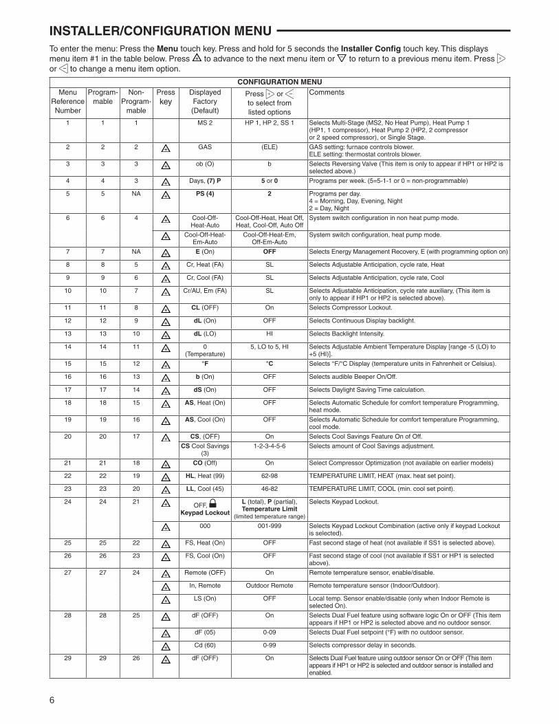
INSTALLER/CONFIGURATION MENUTo enter the menu: Press the Menu touch key. Press and hold for 5 seconds the Installer Confi g touch key. This displays menu item #1 in the table below. Press to advance to the next menu item or to return to a previous menu item. Press or to change a menu item option.
CONFIGURATION MENUMenu
ReferenceNumber
Program-mable
Non-Program-
mable
Press key
Displayed Factory (Default)
Press or to select from listed options
Comments
1 1 1 MS 2 HP 1, HP 2, SS 1 Selects Multi-Stage (MS2, No Heat Pump), Heat Pump 1 (HP1, 1 compressor), Heat Pump 2 (HP2, 2 compressor or 2 speed compressor), or Single Stage.
2 2 2 GAS (ELE) GAS setting: furnace controls blower. ELE setting: thermostat controls blower.
3 3 3 ob (O) b Selects Reversing Valve (This item is only to appear if HP1 or HP2 is selected above.)
4 4 3 Days, (7) P 5 or 0 Programs per week. (5=5-1-1 or 0 = non-programmable)
5 5 NA PS (4) 2 Programs per day. 4 = Morning, Day, Evening, Night 2 = Day, Night
6 6 4 Cool-Off-Heat-Auto
Cool-Off-Heat, Heat Off, Heat, Cool-Off, Auto Off
System switch confi guration in non heat pump mode.
Cool-Off-Heat-Em-Auto
Cool-Off-Heat-Em, Off-Em-Auto
System switch confi guration, heat pump mode.
7 7 NA E (On) OFF Selects Energy Management Recovery, E (with programming option on)
8 8 5 Cr, Heat (FA) SL Selects Adjustable Anticipation, cycle rate, Heat
9 9 6 Cr, Cool (FA) SL Selects Adjustable Anticipation, cycle rate, Cool
10 10 7 Cr/AU, Em (FA) SL Selects Adjustable Anticipation, cycle rate auxiliary, (This item is only to appear if HP1 or HP2 is selected above).
11 11 8 CL (OFF) On Selects Compressor Lockout.
12 12 9 dL (On) OFF Selects Continuous Display backlight.
13 13 10 dL (LO) HI Selects Backlight Intensity.
14 14 11 0(Temperature)
5, LO to 5, HI Selects Adjustable Ambient Temperature Display [range -5 (LO) to +5 (HI)].
15 15 12 °F °C Selects °F/°C Display (temperature units in Fahrenheit or Celsius).
16 16 13 b (On) OFF Selects audible Beeper On/Off.
17 17 14 dS (On) OFF Selects Daylight Saving Time calculation.
18 18 15 AS, Heat (On) OFF Selects Automatic Schedule for comfort temperature Programming, heat mode.
19 19 16 AS, Cool (On) OFF Selects Automatic Schedule for comfort temperature Programming, cool mode.
20 20 17 CS, (OFF) On Selects Cool Savings Feature On of Off.
CS Cool Savings(3)
1-2-3-4-5-6 Selects amount of Cool Savings adjustment.
21 21 18 CO (Off) On Select Compressor Optimization (not available on earlier models)
22 22 19 HL, Heat (99) 62-98 TEMPERATURE LIMIT, HEAT (max. heat set point).
23 23 20 LL, Cool (45) 46-82 TEMPERATURE LIMIT, COOL (min. cool set point).
24 24 21OFF,
Keypad Lockout
L (total), P (partial), Temperature Limit
(limited temperature range)
Selects Keypad Lockout.
000 001-999 Selects Keypad Lockout Combination (active only if keypad Lockoutis selected).
25 25 22 FS, Heat (On) OFF Fast second stage of heat (not available if SS1 is selected above).
26 26 23 FS, Cool (On) OFF Fast second stage of cool (not available if SS1 or HP1 is selected above).
27 27 24 Remote (OFF) On Remote temperature sensor, enable/disable.
In, Remote Outdoor Remote Remote temperature sensor (Indoor/Outdoor).
LS (On) OFF Local temp. Sensor enable/disable (only when Indoor Remote is selected On).
28 28 25 dF (OFF) On Selects Dual Fuel feature using software logic On or OFF (This item appears if HP1 or HP2 is selected above and no outdoor sensor.
dF (05) 0-09 Selects Dual Fuel setpoint (°F) with no outdoor sensor.
Cd (60) 0-99 Selects compressor delay in seconds.
29 29 26 dF (OFF) On Selects Dual Fuel feature using outdoor sensor On or OFF (This item appears if HP1 or HP2 is selected and outdoor sensor is installed and enabled.
7
INSTALLER/CONFIGURATION MENU
1. This control can be confi gured for: MS2 – Multi-Stage System (2 heat/2 cool) HP1 – Heat Pump with one stage of compressor (2
heat/1 cool) HP2 – Heat Pump with two stage compressor or two compressor system, Gas or Electric backup; (Dual Fuel see menu item 28) (4 heat/2 cool) SS1 – Single Stage System (3 wire zone see wiring diagrams.
2. GAS or Electric (ELE) fan operation. If the heating system requires the thermostat to energize the fan, select ELE. Select GAS if the heating system energizes the fan on a call for heat. Note: Resetting the thermostat switches the option to GAS.
3. O/B Terminal selection – Selects the operation of the reversing valve (when item 1 is set to HP1 or HP2 only). When set to "O" the changeover valve will be energized in COOL to accommodate the majority of heat applica-tions. If the heat pump requires the changeover valve to energize in HEAT, select "B".
4. Programs per week – This control can be confi gured for 7 independent day or 5/1/1 day programming or nonpro-grammable modes. Default is 7-day mode. The display indicates "7 Days" as default. Other options "5 Days" or "0 Days" can be selected. If "0 Days" is selected for non-programmable mode, the step for EMR will be skipped, as this feature will not be available in this mode.
5. Program Steps per day – This control can be confi gured for 4 or 2 program steps per day. Default is "4 PS" and can be toggled between 4 PS and 2 PS.
6. System Switch Confi guration (MS2/SS1) – This ther-mostat is confi gured for Heat and Cool with Auto change-over default (Cool-Off-Heat-Auto). It can be confi gured as Heat & Cool (Cool-Off-Heat), or Heat Only (Off-Heat), or Cool Only (Cool-Off).
When the control is in heat pump confi guration (HP1/ HP2), the system switch confi guration will have an additional mode available namely, Em for Emergency Mode.
7. Energy Management Recovery (EMR) – (this step is skipped if confi gured as non-programmable). When set to "On" causes the thermostat to start heating or cooling early to make the building temperature reach the program setpoint at the time you specify.
Example: The heating program is 65°F at night and 70° at 7 AM. If the building temperature is 65°F, the difference is 5°F. Allowing 5 minutes per °F rise, the thermostat set-point will change to 70° at 6:35 AM. Cooling allows more time per °F, because it takes longer to reach temperature.
8, 9 & 10. Cycle Rate Selection – The factory default setting is fast cycle (FA Cr) in all modes (Heat, Cool, Em). To change to slow cycling (SL, Cr), press touch keys or
toggle between FA & SL. The cycle rates are below:
Mode Fast rate Slow rate Heat 0.6°F 1.2°F Cool 1.2°F 1.7°F Em 1.2°F 1.7°F
11. Select Compressor Lockout (CL) – Selecting (CL On) will cause the thermostat to wait 5 minutes between cool-ing cycles. This is intended to help protect the compressor from short cycling. Some of the newer compressors have a time delay built in and do not require this feature to be activated in the thermostat. Your compressor manufactur-er can tell you if this lockout feature is already present in their system. When the thermostat compressor time delay is activated, it will fl ash the set point for up to fi ve minutes.
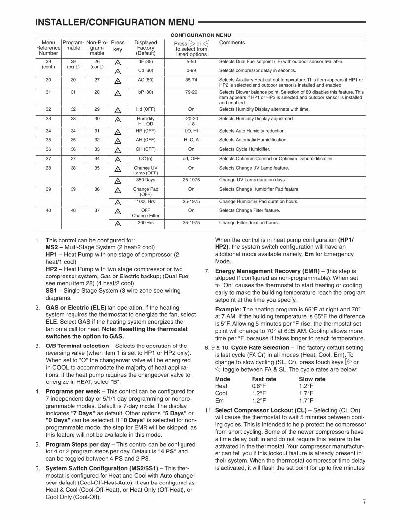
CONFIGURATION MENUMenu
ReferenceNumber
Program-mable
Non-Pro-gram-mable
Press key
Displayed Factory (Default)
Press or to select from listed options
Comments
29(cont.)
29(cont.)
26(cont.)
dF (35) 5-50 Selects Dual Fuel setpoint (°F) with outdoor sensor available.
Cd (60) 0-99 Selects compressor delay in seconds.
30 30 27 AO (80) 35-74 Selects Auxiliary Heat cut out temperature. This item appears if HP1 or HP2 is selected and outdoor sensor is installed and enabled.
31 31 28 bP (80) 79-20 Selects Blower balance point. Selection of 80 disables this feature. This item appears if HP1 or HP2 is selected and outdoor sensor is installed and enabled.
32 32 29 Hd (OFF) On Selects Humidity Display alternate with time.
33 33 30 Humidity H1, OD
-20-20-18
Selects Humidity Display adjustment.
34 34 31 HR (OFF) LO, HI Selects Auto Humidity reduction.
35 35 32 AH (OFF) H, C, A Selects Automatic Humidifi cation.
36 36 33 CH (OFF) On Selects Cycle Humidifi er.
37 37 34 OC (o) od, OFF Selects Optimum Comfort or Optimum Dehumidifi cation.
38 38 35 Change UV Lamp (OFF)
On Selects Change UV Lamp feature.
350 Days 25-1975 Change UV Lamp duration days.
39 39 36 Change Pad (OFF)
On Selects Change Humidifi er Pad feature.
1000 Hrs 25-1975 Change Humidifi er Pad duration hours.
40 40 37 OFFChange Filter
On Selects Change Filter feature.
200 Hrs 25-1975 Change Filter duration hours.
8
12. Select Continuous Backlight – In low lighting condi-tions, display backlight improves the display contrast. When C terminal is connected, selecting dL On will turn the backlight on continuously. Selecting dL Off will turn the backlight on momentarily after any key is pressed. When C terminal is not powered (battery only), dL On enables the momentary backlight whenever a key is pressed.
13. Select Backlight Intensity – This thermostat has the ability to provide two selectable intensities of the back-light: HI and LO. You can toggle the selection between HI and LO.
14. Select Temperature Display Adjustment 5 LO to 5 HI This allows you to adjust the room temperature display by -5°F to +5°F in 1° steps. Your thermostat was accu-rately calibrated at the factory, however you have the option to change the display temperature value to match the previous thermostat, if you so prefer.
15. Select °F or °C Readout – Changes the display readout to Celsius or Fahrenheit as required.
16. Select Audio Prompting (Beeper) On or Off – Factory default setting is b, On. If you wish to turn off the beeper select OFF.
17. Select Daylight Saving Time Calculation – This feature will allow the thermostat to calculate the DST automati-cally and apply it to the Real Time Clock display. Default is On.
18 & 19. Select Automatic Schedule – This feature allows programming a “Comfort Temperature” into all program periods with the Auto Schedule key. When Heat AS (for Heat mode) or Cool AS (for Cool mode) is selected On, the Auto Schedule feature is ready to be set. Off indicates that the feature is not ready to be used or a “Comfort Temperature" is already set. See Auto Schedule in Programming section.
20. Select Cool Savings™: Cool Savings allows you to select a temperature offset (from 1-6 degrees). When the compressor runs for long periods, the thermostat will internally slowly/gradually adjust the room temperature display lower, subtracting a maximum of the number of degrees you select.
This energy saving feature is based on the principal that long compressor run times lower indoor humidity and make a slightly higher temperature feel comfortable. Cool Savings operates only when the compressor runs 20 minutes or longer, normally on the hottest summer days. When Cool Savings is operating the thermostat will fl ash "Cool Savings" to indicate it is slowly adjusting the display temperature lower.
21. Compressor Optimization – (Not available on earlier models) CO provides a delay in circulator fan operation after the compressor turns on or off. With CO selected ON, when the compressor turns on (for a call for heat in heat pump or a call for cool) the fan will be delayed for fi ve seconds before turning on to allow the air to be heated or cooled. After the compressor turns off for call for cool, the fan will continue to run for 20 seconds to capture additional cooling from the system. If CO is set to OFF, there will be no delay in fan operation.
22. Heat Temperature Limit Range – This feature adjusts the highest setpoint temperature for heat. The default set-
ting is 99°F. It can be changed to a setting between 62°F and 98°F. The "temperature limit" icon will be displayed to the left of your setpoint temperature when using this feature. The "temperature limit" icon will fl ash if an attempt is made to adjust the temperature beyond the range selected.
23. Cool Temperature Limit Range – This feature adjusts the lowest setpoint temperature for cool. The default setting is 45°F. It can be changed to a setting between 46°F and 82°F. The "temperature limit" icon will be dis-played to the left of your setpoint temperature when using this feature. The "temperature limit" icon will fl ash if an attempt is made to adjust the temperature beyond the range selected.
24. Keypad Lockout – This step allows you to select the type of lockout or limited range security required. If no lockout or limited range security is required, press to advance the menu.
Three security settings are available in this menu item. Use the or keys to select the lockout desired. Lockout selections are:
"Keypad Lockout and L" = Total Lockout. Total Lockout locks all keys.
"Keypad Lockout and P" = Partial Lockout. Partial Lock-out allows only the or keys to operate within your set temperature limits.
"Temperature Limit/Keypad Lockout" prevents chang-ing the temperature limits in the Confi guration Menu.
After the type of lockout is selected, press .
Keypad Lockout Combination Number Selection Display will read "000" "Keypad Lockout".
Skip this step and continue through the remainder of the confi guration menu if you require an Air Filter Change out indicator or Humidifi er Pad Change out indicator by pressing the key to advance.
Return to this point when you are ready to start your selected lock-out and continue by:
Pressing or keys to select your keypad lockout combination number. Note: "000" is not a valid combina-tion choice.
Record the number you select for future use.
Press to exit the menu. The security feature you select will start in 10 seconds. The system key will remain active for 10 seconds to allow setting Heat, Off, Cool or Auto.
To unlock the keypad, press Menu, then press Installer Confi g. Display will show "000" and keypad lock. Enter the code used to lock the keypad and press .
25 & 26. Select Fast Second Stage, ON or OFF – Selecting FA ON forces additional heat stages to come on quickly when is used to raise the temperature a few degrees above the room. Select this setting if you want the heat to increase quickly when you manually raise the temperature.
Selecting FA OFF allows the thermostat to calculate an optimal time to bring on additional stages of heat. When the is used to raise the setting above the room tem-perature additional heat stages may come on very quickly or very slowly (up to 30 minutes later) depending on recent system performance. Select this setting if you do not require the additional heat stages to come on quickly
INSTALLER/CONFIGURATION MENU
9
when you manually raise the setting and want to allow the thermostat to stage based on recent system performance.
The Fast Cool feature operates the cooling stages in the same manner as Fast Heat, On or Off when the tempera-ture is lowered below the room setting.
27. Select Remote Temperature Sensor – Allows one wired remote temperature sensor (indoor, F145-1328, or outdoor, F145-1378) be connected to it and indicates the measured temperature in clock digits. This item allows you to select the remote sensor and also confi gure it as indoor or outdoor temperature sensor. Factory default is off. Select Remote On and Remote in (for indoor) or Outdoor Remote.
Local Temperature Sensor disable – This is applicable only when indoor remote temperature sensor is enabled. Factory default is On LS. You can make it Off LS if de-sired by using or touch keys. Then, only the indoor remote temperature reading will be used for control.
28. Select Dual Fuel Feature With No Outdoor Sensor (dF) – This feature is applicable only in heat pump modes and with no outdoor sensor. When selected ON, the thermostat will use software logic to determine when to switch to gas heat and shut down the compressor.
Select DF setting (dF) – With DF selected On and no outdoor sensor, select the dF setting from 01-09. Fac-tory default is 05. The dF setting infl uences when second stage comes on. The factory default creates a separation of approximately 1oF between stages. Increasing the set-ting decreases the separation between stages. Decreas-ing the value increases stage separation. This adjust-ment allows a small change in the operation of your heat pump system versus your auxiliary system relative to the thermostat adjustment. The higher the number the sooner the auxiliary stage energizes. The lower the number the longer period of time before auxiliary is energized.
Note: This setting is not minutes or degrees. It is numeric setting that will infl uence the internal thermostat calcula-tion for staging.
Select Compressor Delay (Cd) – After the auxiliary heat is turned on, the compressor(s) shut down is delayed for the time selected (in seconds). This delay is factory set to 60, but can be set in the range of 0 to 99.
29. Select Dual Fuel Feature Using Outdoor Sensor (dF) – This feature is applicable only in heat pump modes and with an outdoor sensor installed and enabled in step 27. When selected ON, the thermostat will use the outdoor sensor temperature to determine when to switch to gas heat and shut down the compressor.
Select DF setting (dF) – With DF selected ON, select the setting for outdoor temperature. When the outdoor tem-perature goes below the selected temperature, the gas heat will begin. Default is 35°, but can be set in the range of 5° to 50°.
Select Compressor Delay (Cd) – After the auxiliary heat is turned on, the compressor(s) shut down is delayed for the time selected (in seconds). This delay is factory set to 60, but can be set in the range of 0 to 99.
30. Select Auxiliary Off (AO) – Select the temperature that will inhibit the auxiliary heating stage. As long as the out-door temperature is above the selected temperature, the auxiliary heat will not turn on. The default setting is 60°, but can be set in the range of 35 ° to 80°.
INSTALLER/CONFIGURATION MENU31. Select Programmable Blower Balance Point (bP) – Re-
quires DHM connection from thermostat to heat pump system. This feature de-energizes the DHM terminal to operate the blower at a slower speed for fi rst stage heat when the outdoor temperature is below the temperature selected. This circulates warmer air than the higher fan speed. The default is 80o (disabled), but can be set from 20o to 79o. Select an outdoor temperature where the air coming out of the ducts begins to feel cool and the ther-mostat will lower the fan speed to circulate warmer air.
32. Humidity Display (Hd) – Selecting HD On enables the display to alternately show the current time and the hu-midity. If HD is selected OFF, the display will not show the humidity.
33. Adjustable Humidity Display – The display will show the ambient humidity and 00 (default). The setting can be changed from -20 and LO to 20 and HI. The displayed humidity will change as the offset is changed. In Run mode, the displayed humidity will be the ambient humidity adjusted by the setting selected.
34. Auto Humidity Reduction (HR) – This feature au-tomatically lowers humidity setting when the outside temperature drops to prevent the interior windows/walls from reaching the dew point where water condenses on surfaces. This feature default is OFF. It can be changed to select LO (low humidity reduction) or HI. To achieve automatic humidity reduction, the thermostat lowers the humidity when furnace cycles are long. When the outside temperature rises, it increases humidity. "LO" indicates a low amount of humidity reduction.
35. Automatic Humidifi cation (AH) – This feature if enabled allows for humidifi cation independent of a call for heating – useful in arid climates where addition humidifi cation in heating and/or cooling is desired. If enabled, will energize the humidifi er and circulator blower (“G” terminal and the “HM” terminal) if the actual humidity is below the humid-ity set point. The display indicates AH. Pressing the key will cycle the display from OFF to H (feature enabled in Heat mode) to C (feature enabled in Cool mode) to A (feature enabled to Auto mode) and back to OFF.
36. Cycle Humidifi er (CH) – This feature provides an op-tion that reduces the water usage by up to 50% when a fl ow-through humidifi er is controlled by the thermostat. It is recommended for use on fl ow-through humidifi ers only. The display indicates CH (Cycle Humidifi er) with the de-fault indicating OFF. Pressing the or keys will toggle the display from OFF to On and back to OFF. When CH is enabled, the humidifi er will cycle to turn off for 10 minutes after it has run for 10 minutes. The blower and/or furnace will continue to run during the humidifi er off period.
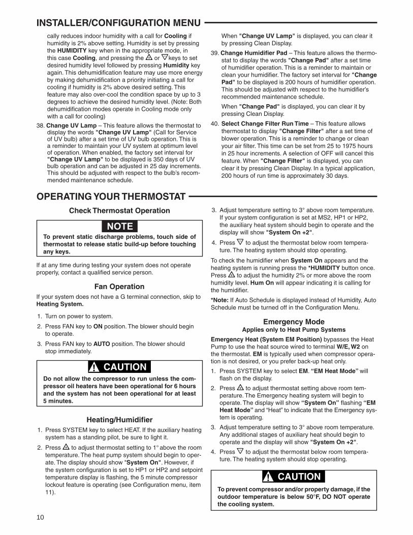
37. Programmable Dehumidifi cation Optimal Comfort Mode (OC) or Optimal Dehumidifi cation (Od) – This item can be selected to OC (Optimal Comfort mode), Od (Optimal Dehumidifi cation), or OFF. When Optimal Com-fort (OC) is enabled, this feature automatically reduces indoor humidity with a call for Cooling if humidity is 2% above humidity setpoint. Humidity is set by pressing the Humidity key when in the appropriate mode, in this case Cooling, and pressing the or keys to set desired humidity (range 40% to 95%) level followed by pressing Humidity key again. This dehumidifi cation feature uses less energy by maintaining temperature and dehumidify-ing only when a call for Cooling is required. Optimal De-humidifi cation (Od) when enabled, this feature automati-
10
cally reduces indoor humidity with a call for Cooling if humidity is 2% above setting. Humidity is set by pressing the HUMIDITY key when in the appropriate mode, in this case Cooling, and pressing the or keys to set desired humidity level followed by pressing Humidity key again. This dehumidifi cation feature may use more energy by making dehumidifi cation a priority initiating a call for cooling if humidity is 2% above desired setting. This feature may also over-cool the condition space by up to 3 degrees to achieve the desired humidity level. (Note: Both dehumidifi cation modes operate in Cooling mode only with a call for cooling)
38. Change UV Lamp – This feature allows the thermostat to display the words "Change UV Lamp" (Call for Service of UV bulb) after a set time of UV bulb operation. This is a reminder to maintain your UV system at optimum level of operation. When enabled, the factory set interval for "Change UV Lamp" to be displayed is 350 days of UV bulb operation and can be adjusted in 25 day increments. This should be adjusted with respect to the bulb’s recom-mended maintenance schedule.
INSTALLER/CONFIGURATION MENU When "Change UV Lamp" is displayed, you can clear it
by pressing Clean Display.
39. Change Humidifi er Pad – This feature allows the thermo-stat to display the words "Change Pad" after a set time of humidifi er operation. This is a reminder to maintain or clean your humidifi er. The factory set interval for "Change Pad" to be displayed is 200 hours of humidifi er operation. This should be adjusted with respect to the humidifi er’s recommended maintenance schedule.
When "Change Pad" is displayed, you can clear it by pressing Clean Display.
40. Select Change Filter Run Time – This feature allows thermostat to display "Change Filter" after a set time of blower operation. This is a reminder to change or clean your air fi lter. This time can be set from 25 to 1975 hours in 25 hour increments. A selection of OFF will cancel this feature. When "Change Filter" is displayed, you can clear it by pressing Clean Display. In a typical application, 200 hours of run time is approximately 30 days.
OPERATING YOUR THERMOSTAT
If at any time during testing your system does not operate properly, contact a qualifi ed service person.
Fan OperationIf your system does not have a G terminal connection, skip to Heating System.
1. Turn on power to system.
2. Press FAN key to ON position. The blower should begin to operate.
3. Press FAN key to AUTO position. The blower should stop immediately.
To prevent static discharge problems, touch side of thermostat to release static build-up before touching any keys.
NOTE
Check Thermostat Operation
Do not allow the compressor to run unless the com-pressor oil heaters have been operational for 6 hours and the system has not been operational for at least 5 minutes.
CAUTION!
Heating/Humidifi er1. Press SYSTEM key to select HEAT. If the auxiliary heating
system has a standing pilot, be sure to light it.
2. Press to adjust thermostat setting to 1° above the room temperature. The heat pump system should begin to oper-ate. The display should show "System On". However, if the system confi guration is set to HP1 or HP2 and setpoint temperature display is fl ashing, the 5 minute compressor lockout feature is operating (see Confi guration menu, item 11).
3. Adjust temperature setting to 3° above room temperature. If your system configuration is set at MS2, HP1 or HP2, the auxiliary heat system should begin to operate and the display will show "System On +2".
4. Press to adjust the thermostat below room tempera-ture. The heating system should stop operating.
To check the humidifi er when System On appears and the heating system is running press the *HUMIDITY button once. Press to adjust the humidity 2% or more above the room humidity level. Hum On will appear indicating it is calling for the humidifi er.
*Note: If Auto Schedule is displayed instead of Humidity, Auto Schedule must be turned off in the Confi guration Menu.
Emergency ModeApplies only to Heat Pump Systems
Emergency Heat (System EM Position) bypasses the Heat Pump to use the heat source wired to terminal W/E, W2 on the thermostat. EM is typically used when compressor opera-tion is not desired, or you prefer back-up heat only.
1. Press SYSTEM key to select EM. “EM Heat Mode” will fl ash on the display.
2. Press to adjust thermostat setting above room tem-perature. The Emergency heating system will begin to operate. The display will show “System On” fl ashing “EM Heat Mode” and “Heat” to indicate that the Emergency sys-tem is operating.
3. Adjust temperature setting to 3° above room temperature. Any additional stages of auxiliary heat should begin to operate and the display will show "System On +2".
4. Press to adjust the thermostat below room tempera-ture. The heating system should stop operating.
To prevent compressor and/or property damage, if the outdoor temperature is below 50°F, DO NOT operate the cooling system.
CAUTION!

11
Choose the System Setting(Cool, Off, Heat, Em, Auto)Press the SYSTEM key to select:Cool: Thermostat controls only the cooling system.
Off: Heating and Cooling systems are off.
Heat: Thermostat controls only the heating system.
Em: Setting is available only when the thermostat is confi g-ured in HP1 or HP2 mode.
Auto: Auto Changeover is used in areas where both heating and cooling may be required on the same day. AUTO allows the thermostat to automatically select heating or cooling depending on the indoor temperature and the selected heat and cool temperatures. When using AUTO, be sure to set the Cooling temperatures more than 1° Fahrenheit higher than the heating temperature.
Manual Operation forNon-Programmable ModePress the SYSTEM key to select "Heat" or "Cool" and usethe keys to adjust the temperature to your desired setting. After selecting your desired settings you can also press the SYSTEM key to select AUTO to allow the thermostat to auto-matically change between "Heat" and "Cool".
Manual Operation (Bypassing the Program)Programmable ModeManual operation will bypass the program and allow you to adjust the temperature as you desire. The temperature you set in Hold will be maintained indefi nitely. Press or to adjust the temperature. The HOLD key will appear. Press the HOLD key. "Hold At" will appear next to the setpoint tem-perature and the thermostat will maintain the new setpoint temperature until Run Schedule is pressed to resume pro-gram operation.
Program Override (Temporary Override)Press or keys to adjust the temperature. This will over-ride the temperature setting for a (default) four hour override period. The override period can be shortened by pressing or lengthened by pressing . Program Override period can range from 15 minutes to 7 days.
Example: If you turn up the heat during the morning program, it will be automatically lowered later, when the temporary hold period ends. To cancel the temporary setting at any time and return to the program, press Run Schedule.
If the SYSTEM key is pressed to select AUTO thethermostat will change to "Heat" or "Cool", whichever ran last. If it switches to "Heat", but you want "Cool", or it changes to "Cool", but you want "Heat", press both keys simultaneously to change to the other mode.
OPERATING YOUR THERMOSTATCooling/Dehumidifi er
1. Press SYSTEM to select "Cool".
2. Press to adjust the thermostat setting below room tem-perature. The blower should come on immediately on high speed, followed by cold air circulation. The display should show "System On". If the setpoint temperature display is fl ashing, the compressor lockout feature is operating (see Confi guration menu, item 5).
3. Adjust temperature setting to 3° below room temperature. The second stage cooling should begin to operate and the display should show "System On +2".
4. Press to adjust the temperature setting above room temperature. The cooling system should stop operating.
To check the dehumidifi er when System On appears and the cooling system is running press *HUMIDITY button once. Press to adjust the humidity 2% or more below the room humidity level. DeHum On will appear indicating it is calling for the dehumidifi cation.
If the room humidity is lower than the adjustment range, press to 40% and hold it for four seconds. This will force the
DeHum On for one complete cooling cycle to test the dehu-midifi cation equipment.
After adjusting the humidity setting the display will return to temperature in approximately 10 seconds. To switch the dis-play back to temperature immediately after adjusting humidity setting press HUMIDITY again.
*Note: If Auto Schedule is displayed instead of Humidity, Auto Schedule must be turned off in the Confi guration Menu.
Choose the Fan Setting (Auto or On or Prog)There are three fan features on the 1F95-1291:
1. Fan Auto/On – Traditional Fan Settings Press Fan to select Auto or On. The most commonly
used setting is Auto. Fan Auto runs the fan only when the heating or cooling system is operating. Selecting Fan On runs the fan continuously for increased air circulation or to allow additional air cleaning if the system is equipped with an Electronic Air Cleaner.
2. FAN Prog – Comfort Circulating Fan Feature Pressing FAN until FAN Prog appears activates the Com-
fort Circulating Fan Option. This causes the thermostat to cycle the fan on for 10 minutes and off for 20 minutes if the thermostat has not called for heat or cool during the past 60 minutes. This assures moderate air circulation even when the heating and cooling equipment is not cycling.
3. FAN On Prog. – Programmable Fan FAN On Prog indicates that a time period has FAN Prog
selected in the Set Schedule mode (see Programmable Fan Option). The fan will run continuously through the pe-riod until the next period begins. To override FAN On Prog, press the FAN key to select Auto for the fan to run only when the heating or cooling system is operating.
Tip: Running the fan more frequently will increase your energy consumption. Most systems use a 1/2 or 1/3 HP electric motor to power the fan.
12
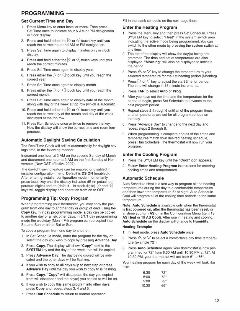
PROGRAMMINGSet Current Time and Day1. Press Menu key to enter installer menu. Then press Set Time once to indicate hour & AM or PM designation
in clock display.
2. Press and hold either the or touch key until you reach the correct hour and AM or PM designation.
3. Press Set Time again to display minutes only in clock display.
4. Press and hold either the or touch keys until you reach the correct minutes.
5. Press Set Time once again to display year.
6. Press either the or touch key until you reach the correct year.
7. Press Set Time once again to display month.
8. Press either the or touch key until you reach the correct month.
9. Press Set Time once again to display date of the month along with day of the week at top row (which is automatic).
10. Press and hold either the or touch key until you reach the correct day of the month and day of the week displayed at the top row.
11. Press Run Schedule once or twice to remove the key. Now the display will show the correct time and room tem-perature.
Automatic Daylight Saving CalculationThe Real Time Clock will adjust automatically for daylight sav-ings time, in the following manner:
Increment one hour at 2 AM on the second Sunday of March and decrement one hour at 2 AM on the fi rst Sunday of No-vember. (New DST effective 2007).
The daylight saving feature can be enabled or disabled in installer confi guration menu. Default is DS ON (enabled).After entering installer confi guration mode, momentarilypress touch key until the display indicates dS (in actual tem-perature digits) and on (default – in clock digits). and keys will toggle display and operation from on to OFF.
Programming Tip: Copy ProgramWhen programming your thermostat, you may copy the pro-gram from one day to another day or group of days using the Copy key. In 7 day programming mode, a day can be copied to another day or all six other days. In 5/1/1 day programming mode the weekday (Mon – Fri) program can be copied into Sat and Sun or either Sat or Sun.
To copy a program from one day to another:
1. In Set Schedule mode, enter the program for the day or select the day you wish to copy by pressing Advance Day.
2. Press Copy. The display will show “Copy” next to the SYSTEM key and the day of the week that will be copied.
3. Press Advance Day. The day being copied will be indi-cated and the other days will be fl ashing.
4. If you wish to copy to all days skip to next step or press Advance Day until the day you wish to copy to is fl ashing.
5. Press Copy. “Copy” will disappear, the day you copied from will disappear and the day(s) you copied to will be on.
6. If you wish to copy this same program into other days, press Copy and repeat steps 3, 4 and 5.
7. Press Run Schedule to return to normal operation.
Fill in the blank schedule on the next page then:
Enter the Heating Program1. Press the Menu key and then press Set Schedule. Press
SYSTEM key to select "Heat" in the system switch area indicating the active mode being programmed. You can switch to the other mode by pressing the system switch at any time.
2. The top of the display will show the day(s) being pro-grammed. The time and set at temperature are also displayed. "Morning" will also be displayed to indicate the period.
3. Press or key to change the temperature to your selected temperature for the 1st heating period (Morning).
4. Press or key to adjust the start time for period. The time will change in 15 minute increments.
5. Press FAN to select Auto or Prog.
6. After you have set the time and the temperature for the period to begin, press Set Schedule to advance to the next program period.
7. Repeat steps 2 through 6 until all of the program times and temperatures are set for all program periods on that day.
8. Press "Advance Day" to change to the next day and repeat steps 2 through 8.
9. When programming is complete and all of the times and temperatures match your desired heating schedule, press Run Schedule. The thermostat will now run your program.
Enter the Cooling Program1. Press the SYSTEM key until the "Cool" icon appears.
2. Follow Enter Heating Program instructions for entering cooling times and temperatures.
Automatic ScheduleAuto Schedule Heat is a fast way to program all the heating temperatures during the day to a comfortable temperature and then lower the temperature 6° at night. Auto Schedule Cool will program all of the cooling time periods to the same temperature.
Note: Auto Schedule is available only when the thermostat is fi rst powered on, after the thermostat has been reset, or anytime you turn AS on in the Confi guration Menu (item 18 AS Heat or 19 AS Cool). After use in heating and cooling, Auto Schedule on the display will change to Humidity.
Heating Example:
1. In Heat mode, press Auto Schedule once.
2. Press or to select a comfortable day time tempera-ture (example 72°).
3. Press Auto Schedule again. Your thermostat is now pro-grammed for 72° from 6:30 AM until 10:30 PM at 72°. At 10:30 PM, your thermostat will set back 6° to 66°.
Your heating program for each day of the week will look like this:
6:30 72° 8:00 72° 5:00 72° 10:30 66°
13
PROGRAMMING
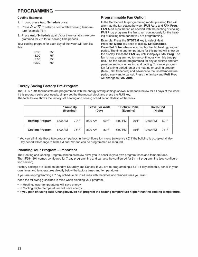
Planning Your Program – ImportantThe Heating and Cooling Program schedules below allow you to pencil in your own program times and temperatures.The 1F95-1291 comes confi gured for 7 day programming and can also be confi gured for 5+1+1 programming (see confi gura-tion section).
Factory settings are listed on Monday, Saturday and Sunday. If you are re-programming a 5+1+1 day schedule, pencil in your own times and temperatures directly below the factory times and temperatures.
If you are re-programming a 7 day schedule, fi ll in all lines with the times and temperatures you want.
Keep the following guidelines in mind when planning your program.
• In Heating, lower temperatures will save energy.• In Cooling, higher temperatures will save energy.• If you plan on using Auto Changeover, do not program the heating temperature higher than the cooling temperature.
Energy Saving Factory Pre-ProgramThe 1F95-1291 thermostats are programmed with the energy saving settings shown in the table below for all days of the week. If this program suits your needs, simply set the thermostat clock and press the RUN key.The table below shows the factory set heating and cooling schedule for all days of the week.
* You can eliminate these two program periods in the confi guration menu (reference #5) if the building is occupied all day. Day period will change to 6:00 AM and 70° and can be programmed as required.
* Wake Up(Morning)
Leave For Work(Day)
* Return Home(Evening)
Go To Bed (Night)
Heating Program 6:00 AM 70°F 8:00 AM 62°F 5:00 PM 70°F 10:00 PM 62°F
Cooling Program 6:00 AM 75°F 8:00 AM 83°F 5:00 PM 75°F 10:00 PM 78°F
Programmable Fan OptionIn the Set Schedule (programming mode) pressing Fan will alternate the fan setting between FAN Auto and FAN Prog. FAN Auto runs the fan as needed with the heating or cooling. FAN Prog programs the fan to run continuously for the heat-ing or cooling time period you are programming.
Example: Press the SYSTEM key to select Heat.Press the Menu key once to display Set Schedule.Press Set Schedule once to display the 1st heating program period. The time and temperature for this period will show on the display. Press the FAN key until it displays FAN Prog. The fan is now programmed to run continuously for this time pe-riod. The fan can be programmed for any or all time and tem-perature settings in heating and cooling. To cancel program fan for a time period, enter the heating or cooling program (Menu, Set Schedule) and advance to the time/temperature period you want to cancel. Press the fan key and FAN Prog will change to FAN Auto.
Cooling Example:
1. In cool, press Auto Schedule once.
2. Press or to select a comfortable cooling tempera-ture (example 75°).
3. Press Auto Schedule again. Your thermostat is now pro-grammed for 75° for all cooling time periods.
Your cooling program for each day of the week will look like this:
6:30 75° 8:00 75° 5:00 75° 10:30 75°
14
PROGRAMMING
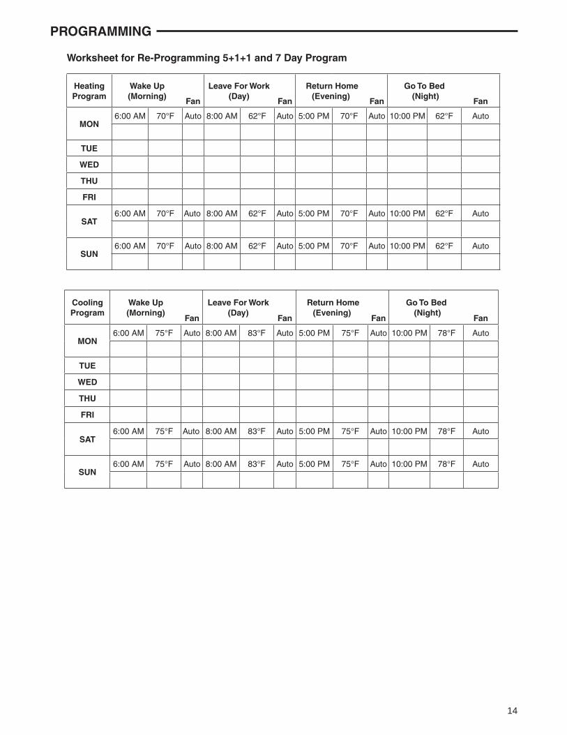
CoolingProgram
Wake Up(Morning)
Fan
Leave For Work(Day)
Fan
Return Home(Evening)
Fan
Go To Bed (Night)
Fan
MON6:00 AM 75°F Auto 8:00 AM 83°F Auto 5:00 PM 75°F Auto 10:00 PM 78°F Auto
TUE
WED
THU
FRI
SAT6:00 AM 75°F Auto 8:00 AM 83°F Auto 5:00 PM 75°F Auto 10:00 PM 78°F Auto
SUN6:00 AM 75°F Auto 8:00 AM 83°F Auto 5:00 PM 75°F Auto 10:00 PM 78°F Auto
Worksheet for Re-Programming 5+1+1 and 7 Day Program
HeatingProgram
Wake Up(Morning)
Fan
Leave For Work(Day)
Fan
Return Home(Evening)
Fan
Go To Bed (Night)
Fan
MON6:00 AM 70°F Auto 8:00 AM 62°F Auto 5:00 PM 70°F Auto 10:00 PM 62°F Auto
TUE
WED
THU
FRI
SAT6:00 AM 70°F Auto 8:00 AM 62°F Auto 5:00 PM 70°F Auto 10:00 PM 62°F Auto
SUN6:00 AM 70°F Auto 8:00 AM 62°F Auto 5:00 PM 70°F Auto 10:00 PM 62°F Auto
15
Wired Remote Temperature SensingOne remote temperature sensor can be installed indoor or outdoor and connected to the thermostat by a maximum cable length of 100 meters (300 feet). Terminals +, S and - on the terminal block allow connection of the remote sensor. The thermostat must have 24 VAC Common connection to terminal C for the remote sensor to operate. The remote sen-sor can be enabled or disabled in the Installer/Confi guration menu, item 27.
When remote sensor, Remote, is selected Off (factory de-fault), no remote sensor is enabled. When remote sensor is selected On, the next step is to select the remote as indoor, Remote In, or outdoor, Remote Outdoor. If the remote is se-lected as Remote In, an additional step will be to select if the temperature shown on the display will be from the thermostat, LS On, or the remote sensor LS Off.
In normal operation, when a remote sensor is enabled the time digits of the display will alternate between the time and the remote temperature for three seconds each. Above the remote temperature will be Remote, for indoor sensor or Outdoor Remote, for outdoor sensor. If the remote sensor is an indoor sensor and the local display has been disabled, the temperature displayed as the room temperature will be the remote sensor temperature.
Sensing Range: Outdoor temperature range is -40oF to 140oF Indoor temperature range is 32oF to 99 oF
Averaging or Weighting Remote SensorsThe thermostat will weight or average the temperature of the indoor remote sensor with the local sensor in the thermostat for each program period. The averaging will be active only when the local sensor and the indoor remote sensor are both functional and enabled in the Installer/Confi guration menu.
When the thermostat is in the Set Schedule mode, the weight of the indoor sensor will be shown in the current temperature digits of the display. The weight will show as A2 (average and default), H4 (high) or L1 (low). Pressing the and keys at the same time will change the weight for the program period. The weight of the thermostat sensor is fi xed.
In normal operation of the thermostat, the current tempera-ture displayed will be the weighted average of the local sensor and the remote sensor using the formula (local sensor weight x local sensor temperature) + (remote sensor weight x remote sensor temperature) / (local sensor weight + remote sensor weight).
Example: Local sensor temperature is 80° and the remote sensor is 70°. If weight is selected H4, the averaged temperature of 72° will be displayed.(1 x 80) + (4 x 70) / 5 = 72°
If weight is selected A2, the average temperature of 73° will be displayed.(1 x 80) + (2 x 70) / 3 = 73.3°
If weight is selected L1, the average temperature of 75° will be displayed.(1 x 80) + (1 x 70) / 2 = 75°
PROGRAMMINGThe example shows that the weight selected would prioritize the overall averaged temperature between the two sensors. The high weight selection caused the remote sensor to have a higher infl uence in the calculated temperature average than the local sensor and the low weight selection caused the remote sensor to have less infl uence.
Dual Fuel Temperature SetpointWhen the thermostat is confi gured for Heat Pump mode and the Dual Fuel feature is selected on, the thermostat can moni-tor the outside temperature using remote sensor F145-1378 or use software logic to determine when to switch to gas heat and shut down the compressor. This eliminates the need for a fossil fuel kit.
The user selectable temperature is called the dual fuel tem-perature setpoint, dF and is set in the Installer/Confi guration menu, items 28 or 29. With outdoor remote sensor installed and enabled, the dual fuel temperature setpoint (menu item 29) can be set to a temperature of 5° through 50°. When outdoor remote sensor is not installed, a software logic based dual fuel number (menu item 28) from 01 to 09 can be selected.
After the dual fuel temperature setpoint is set and is pressed, a delay, Cd, can be set for compressor shutdown after the auxiliary stage is energized. This delay can be set from 0 seconds to 99 seconds to minimize the time that the system may blow cooler air until the alternate source of heat comes on. Default setting for delay is 60. When setting the delay, if the or keys are held depressed, the setpoint will increase or decrease at the rate of one degree every half second for the fi rst three seconds and double the speed after three seconds.
Blower Balance Point for HeatingRequires DHM connection from thermostat to heat pump system. Air to air heat pumps use a fast fan speed to circu-late warm air for fi rst stage heating. As outdoor temperatures drop, the heat pump produces less heat and a high fan speed makes the air from the ducts feel cooler. Blower Balance Point allows you to select an outdoor temperature to slow the fan speed so the air from the duct feels warmer. Select an out-door temperature where the air from the ducts starts to feel cool (Installer Confi guration Menu item 31). When the outdoor temperature drops to the selected temperature, the thermo-stat will slow the fan speed so the outlet air feels warmer.
16www.white-rodgers.com
White-Rodgers is a divisionof Emerson Electric Co.
The Emerson logo is a trademark and service markof Emerson Electric Co.
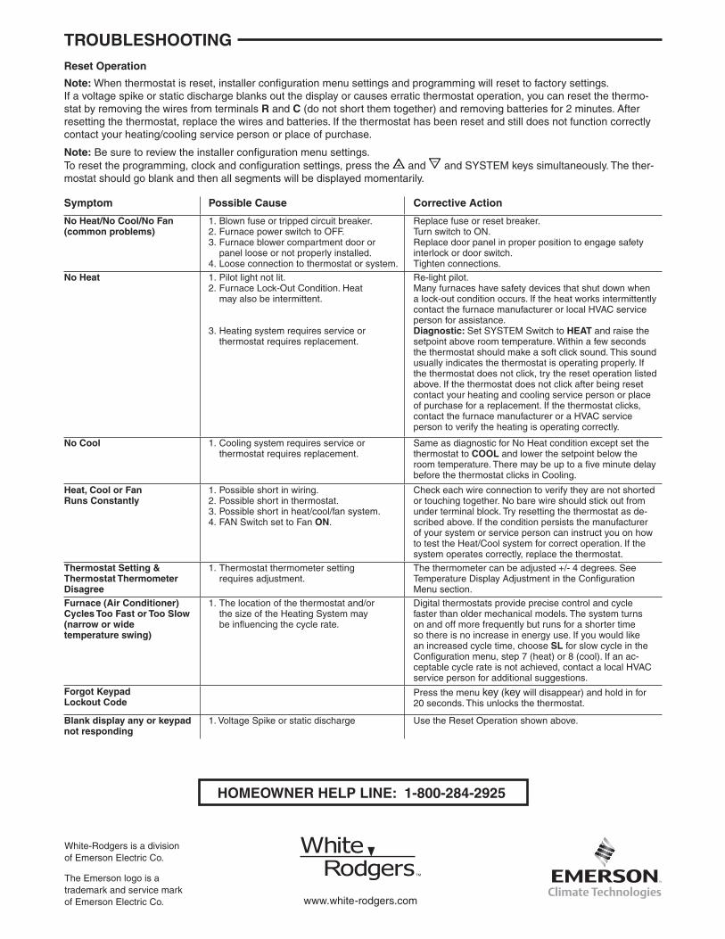
HOMEOWNER HELP LINE: 1-800-284-2925
TROUBLESHOOTING
Symptom Possible Cause Corrective Action
No Heat/No Cool/No Fan(common problems)
1. Blown fuse or tripped circuit breaker.2. Furnace power switch to OFF.3. Furnace blower compartment door or panel loose or not properly installed.4. Loose connection to thermostat or system.
Replace fuse or reset breaker.Turn switch to ON.Replace door panel in proper position to engage safety interlock or door switch.Tighten connections.
No Heat 1. Pilot light not lit.2. Furnace Lock-Out Condition. Heat may also be intermittent.
3. Heating system requires service or thermostat requires replacement.
Re-light pilot.Many furnaces have safety devices that shut down when a lock-out condition occurs. If the heat works intermittently contact the furnace manufacturer or local HVAC service person for assistance.Diagnostic: Set SYSTEM Switch to HEAT and raise the setpoint above room temperature. Within a few seconds the thermostat should make a soft click sound. This sound usually indicates the thermostat is operating properly. If the thermostat does not click, try the reset operation listed above. If the thermostat does not click after being reset contact your heating and cooling service person or place of purchase for a replacement. If the thermostat clicks, contact the furnace manufacturer or a HVAC service person to verify the heating is operating correctly.
No Cool
1. Cooling system requires service or thermostat requires replacement.
Same as diagnostic for No Heat condition except set the thermostat to COOL and lower the setpoint below the room temperature. There may be up to a fi ve minute delay before the thermostat clicks in Cooling.
Heat, Cool or FanRuns Constantly
1. Possible short in wiring.2. Possible short in thermostat.3. Possible short in heat/cool/fan system.4. FAN Switch set to Fan ON.
Check each wire connection to verify they are not shorted or touching together. No bare wire should stick out from under terminal block. Try resetting the thermostat as de-scribed above. If the condition persists the manufacturer of your system or service person can instruct you on how to test the Heat/Cool system for correct operation. If the system operates correctly, replace the thermostat.
Thermostat Setting &Thermostat Thermometer Disagree
1. Thermostat thermometer setting requires adjustment.
The thermometer can be adjusted +/- 4 degrees. See Temperature Display Adjustment in the Confi guration Menu section.
Furnace (Air Conditioner)Cycles Too Fast or Too Slow (narrow or wide temperature swing)
1. The location of the thermostat and/or the size of the Heating System may be infl uencing the cycle rate.
Digital thermostats provide precise control and cycle faster than older mechanical models. The system turns on and off more frequently but runs for a shorter time so there is no increase in energy use. If you would like an increased cycle time, choose SL for slow cycle in the Confi guration menu, step 7 (heat) or 8 (cool). If an ac-ceptable cycle rate is not achieved, contact a local HVAC service person for additional suggestions.
Forgot KeypadLockout Code
Press the menu key (key will disappear) and hold in for 20 seconds. This unlocks the thermostat.
Blank display any or keypad not responding
1. Voltage Spike or static discharge Use the Reset Operation shown above.
Reset Operation
Note: When thermostat is reset, installer confi guration menu settings and programming will reset to factory settings.If a voltage spike or static discharge blanks out the display or causes erratic thermostat operation, you can reset the thermo-stat by removing the wires from terminals R and C (do not short them together) and removing batteries for 2 minutes. After resetting the thermostat, replace the wires and batteries. If the thermostat has been reset and still does not function correctly contact your heating/cooling service person or place of purchase.
Note: Be sure to review the installer confi guration menu settings.To reset the programming, clock and confi guration settings, press the and and SYSTEM keys simultaneously. The ther-mostat should go blank and then all segments will be displayed momentarily.