How can I … Select PlantStruxure reference
architectures?
Design Your architecture
System Technical Note
PlantStruxure reference architecture

© 2012 Schneider Electric All Rights Reserved
3
Important Information
People responsible for the application, implementation and use of this document must make sure
that all necessary design considerations have been taken into account and that all laws, safety
and performance requirements, regulations, codes, and applicable standards have been obeyed
to their full extent.
Schneider Electric provides the resources specified in this document. These resources can be
used to minimize engineering efforts, but the use, integration, configuration, and validation of the
system is the user’s sole responsibility. Said user must ensure the safety of the system as a
whole, including the resources provided by Schneider Electric through procedures that the user
deems appropriate.
Notice
This document is not comprehensive for any systems using the given architecture and does not
absolve users of their duty to uphold the safety requirements for the equipment used in their
systems, or compliance with both national or international safety laws and regulations.
Readers are considered to already know how to use the products described in this document.
This document does not replace any specific product documentation.
The following special messages may appear throughout this documentation or on the equipment
to warn of potential hazards or to call attention to information that clarifies or simplifies a
procedure.
The addition of this symbol to a Danger or Warning safety label indicates that an
electrical hazard exists, which will result in personal injury if the instructions are not
followed.
This is the safety alert symbol. It is used to alert you to potential personal injury hazards.
Obey all safety messages that follow this symbol to avoid possible injury or death.
DANGER
DANGER indicates an imminently hazardous situation which, if not avoided, will result in death
or serious injury.
Failure to follow these instructions will result in death or serious injury.
© 2012 Schneider Electric All Rights Reserved
4
WARNING
WARNING indicates a potentially hazardous situation which, if not avoided, can result in death
or serious injury.
Failure to follow these instructions can cause death, serious injury or equipment
damage.
CAUTION
CAUTION indicates a potentially hazardous situation which, if not avoided, can result in minor
or moderate injury.
Failure to follow these instructions can result in injury or equipment damage.
NOTICE
NOTICE is used to address practices not related to physical injury.
Failure to follow these instructions can result in equipment damage.
Note: Electrical equipment should be installed, operated, serviced, and maintained only by
qualified personnel. No responsibility is assumed by Schneider Electric for any consequences
arising out of the use of this material.
A qualified person is one who has skills and knowledge related to the construction, operation and
installation of electrical equipment, and has received safety training to recognize and avoid the
hazards involved.
Before You Begin
This automation equipment and related software is used to control a variety of industrial
processes. The type or model of automation equipment suitable for each application will vary
depending on factors such as the control function required, degree of protection required,
production methods, unusual conditions and government regulations etc. In some applications
more than one processor may be required when backup redundancy is needed.
Only the user can be aware of all the conditions and factors present during setup, operation and
maintenance of the solution. Therefore only the user can determine the automation equipment
and the related safeties and interlocks which can be properly used. When selecting automation
and control equipment and related software for a particular application, the user should refer to
© 2012 Schneider Electric All Rights Reserved
5
the applicable local and national standards and regulations. The National Safety Council’s
Accident Prevention Manual also provides much useful information.
Ensure that appropriate safeties and mechanical/electrical interlocks protection have been
installed and are operational before placing the equipment into service. All mechanical/electrical
interlocks and safeties protection must be coordinated with the related automation equipment and
software programming.
Note: Coordination of safeties and mechanical/electrical interlocks protection is outside the scope
of this document.
START UP AND TEST
Following installation but before using electrical control and automation equipment for regular
operation, the system should be given a start up test by qualified personnel to verify the correct
operation of the equipment. It is important that arrangements for such a check be made and that
enough time is allowed to perform complete and satisfactory testing.
WARNING
EQUIPMENT OPERATION HAZARD
Follow all start up tests as recommended in the equipment documentation.
Store all equipment documentation for future reference.
Software testing must be done in both simulated and real environments.
Failure to follow these instructions can cause death, serious injury or equipment
damage.
Verify that the completed system is free from all short circuits and grounds, except those grounds
installed according to local regulations (according to the National Electrical Code in the USA, for
example). If high-potential voltage testing is necessary, follow recommendations in the equipment
documentation to prevent accidental equipment damage.
Before energizing equipment:
Remove tools, meters, and debris from equipment
Close the equipment enclosure door
Remove ground from incoming power lines
Perform all start-up tests recommended by the manufacturer
© 2012 Schneider Electric All Rights Reserved
6
OPERATION AND ADJUSTMENTS
The following precautions are from NEMA Standards Publication ICS 7.1-1995 (English version
prevails):
Regardless of the care exercised in the design and manufacture of equipment or in the selection
and rating of components; there are hazards that can be encountered if such equipment is
improperly operated.
It is sometimes possible to misadjust the equipment and thus produce unsatisfactory or unsafe
operation. Always use the manufacturer’s instructions as a guide for functional adjustments.
Personnel who have access to these adjustments should be familiar with the equipment
manufacturer’s instructions and the machinery used with the electrical equipment.
Only those operational adjustments actually required by the operator should be accessible to the
operator. Access to other controls should be restricted to prevent unauthorized changes in
operating characteristics.
WARNING
UNEXPECTED EQUIPMENT OPERATION
Only use software tools approved by Schneider Electric for use with this equipment.
Update your application program every time you change the physical hardware
configuration.
Failure to follow these instructions can cause death, serious injury or equipment
damage.
INTENTION
This document is intended to provide a quick introduction to the described system. It is not
intended to replace any specific product documentation, nor any of your own design
documentation. On the contrary, it offers information additional to the product documentation on
installation, configuration and implementing the system.
The architecture described in this document is not a specific product in the normal commercial
sense. It describes an example of how Schneider Electric and third-party components may be
integrated to fulfill an industrial application.
A detailed functional description or the specifications for a specific user application is not part of
this document. Nevertheless, the document outlines some typical applications where the system
might be implemented.
© 2012 Schneider Electric All Rights Reserved
7
The architecture described in this document has been fully tested in our laboratories using all the
specific references you will find in the component list near the end of this document. Of course,
your specific application requirements may be different and will require additional and/or different
components. In this case, you will have to adapt the information provided in this document to
your particular needs. To do so, you will need to consult the specific product documentation of the
components that you are substituting in this architecture. Pay particular attention in conforming to
any safety information, different electrical requirements and normative standards that would apply
to your adaptation.
It should be noted that there are some major components in the architecture described in this
document that cannot be substituted without completely invalidating the architecture,
descriptions, instructions, wiring diagrams and compatibility between the various software and
hardware components specified herein. You must be aware of the consequences of component
substitution in the architecture described in this document as substitutions may impair the
compatibility and interoperability of software and hardware.
CAUTION
EQUIPMENT INCOMPATIBILITY OR INOPERABLE EQUIPMENT
Read and thoroughly understand all hardware and software documentation before attempting
any component substitutions.
Failure to follow these instructions can result in injury or equipment damage.
© 2012 Schneider Electric All Rights Reserved
8
This document is intended to describe classes of reference architecture for PlantStruxure. These
classes of architecture can be used for multiple vertical applications.
DANGER
HAZARD OF ELECTRIC SHOCK, BURN OR EXPLOSION
Only qualified personnel familiar with low and medium voltage equipment are to perform
work described in this set of instructions. Workers must understand the hazards involved in
working with or near low and medium voltage circuits.
Perform such work only after reading and understanding all of the instructions contained in
this bulletin.
Turn off all power before working on or inside equipment.
Use a properly rated voltage sensing device to confirm that the power is off.
Before performing visual inspections, tests, or maintenance on the equipment, disconnect
all sources of electric power. Assume that all circuits are live until they have been
completely de-energized, tested, grounded, and tagged. Pay particular attention to the
design of the power system. Consider all sources of power, including the possibility of back
feeding.
Handle this equipment carefully and install, operate, and maintain it correctly in order for it
to function properly. Neglecting fundamental installation and maintenance requirements
may lead to personal injury, as well as damage to electrical equipment or other property.
Beware of potential hazards, wear personal protective equipment and take adequate safety
precautions.
Do not make any modifications to the equipment or operate the system with the interlocks
removed. Contact your local field sales representative for additional instruction if the
equipment does not function as described in this manual.
Carefully inspect your work area and remove any tools and objects left inside the
equipment.
Replace all devices, doors and covers before turning on power to this equipment.
All instructions in this manual are written with the assumption that the customer has taken
these measures before performing maintenance or testing.
Failure to follow these instructions will result in death or serious injury.
© 2012 Schneider Electric All Rights Reserved
9
The STN Collection
The implementation of an automation project includes five main phases: Selection, Design,
Configuration, Implementation and Operation. To help you develop a project based on these
phases, Schneider Electric has created the Tested, Validated, Documented Architecture and
System Technical Note.
A Tested, Validated, Documented Architecture (TVDA) provides technical guidelines and
recommendations for implementing technologies to address your needs and requirements, This
guide covers the entire scope of the project life cycle, from the Selection to the Operation phase,
providing design methodologies and source code examples for all system components.
A System Technical Note (STN) provides a more theoretical approach by focusing on a particular
system technology. These notes describe complete solution offers for a system, and therefore
support you in the Selection phase of a project. The TVDAs and STNs are related and
complementary. In short, you will find technology fundamentals in an STN and their
corresponding applications in one or several TVDAs.
Development Environment
Each TVDA or STN has been developed in one of our solution platform labs using a typical
PlantStruxure architecture.
PlantStruxure, the process automation system from Schneider Electric, is a collaborative
architecture that allows industrial and infrastructure companies to meet their automation needs
while at the same time addressing their growing energy efficiency requirements. In a single
environment, measured energy and process data can be analyzed to yield a holistically optimized
plant.

© 2012 Schneider Electric All Rights Reserved
10
© 2012 Schneider Electric All Rights Reserved
11
Table of Contents
1. Introduction 13
1.1. Purpose 13
1.2. Customer challenges 14
1.3. PlantStruxure architecture overview 14
1.4. PlantStruxure reference architecture principles 16
1.5. Glossary 16
2. Selection 17
2.1. Reference architecture description 17
2.2. PlantStruxure technological axis 18
2.3. PlantStruxure functional axis 20
2.4. Application axis 21
2.5. PlantStruxure Libraries 21
3. PlantStruxure global reference architecture 23
3.1. Global reference architecture structuring 23
3.2. Overall network architecture 23
3.3. PlantStruxure centralized architecture 25
3.4. PlantStruxure modular architecture 26
3.5. PlantStruxure large process architecture 29
3.6. PlantStruxure global architecture selection summary 32
4. Control room reference architectures 33
4.1. Control room architecture structuring 33
4.2. PlantStruxure compact control room 34
4.3. PlantStruxure process control room 35
4.4. PlantStruxure plant operation center 36
4.5. Control room architecture selection summary 38
5. Functional unit reference architectures 39
5.1. Functional unit architecture structuring 39
5.2. PlantStruxure traditional functional unit 43
5.3. PlantStruxure optimized functional unit 45
5.4. PlantStruxure high service functional unit 48
© 2012 Schneider Electric All Rights Reserved
12
6. PlantStruxure reference architecture examples 55
7. Appendix 59
7.1. Glossary 59
7.2. Graphics 60
1 – Introduction
© 2012 Schneider Electric All Rights Reserved
13
1. Introduction
1.1. Purpose
The intent of this system technical note is to provide guidelines and recommendations to assist in
selecting the PlantStruxure reference architecture that corresponds to the process or project
requirements.
PlantStruxure, the Process Automation System from Schneider Electric, is a collaborative system
that:
Allows industrial and infrastructure companies to meet their automation needs
Delivers on growing energy management requirements
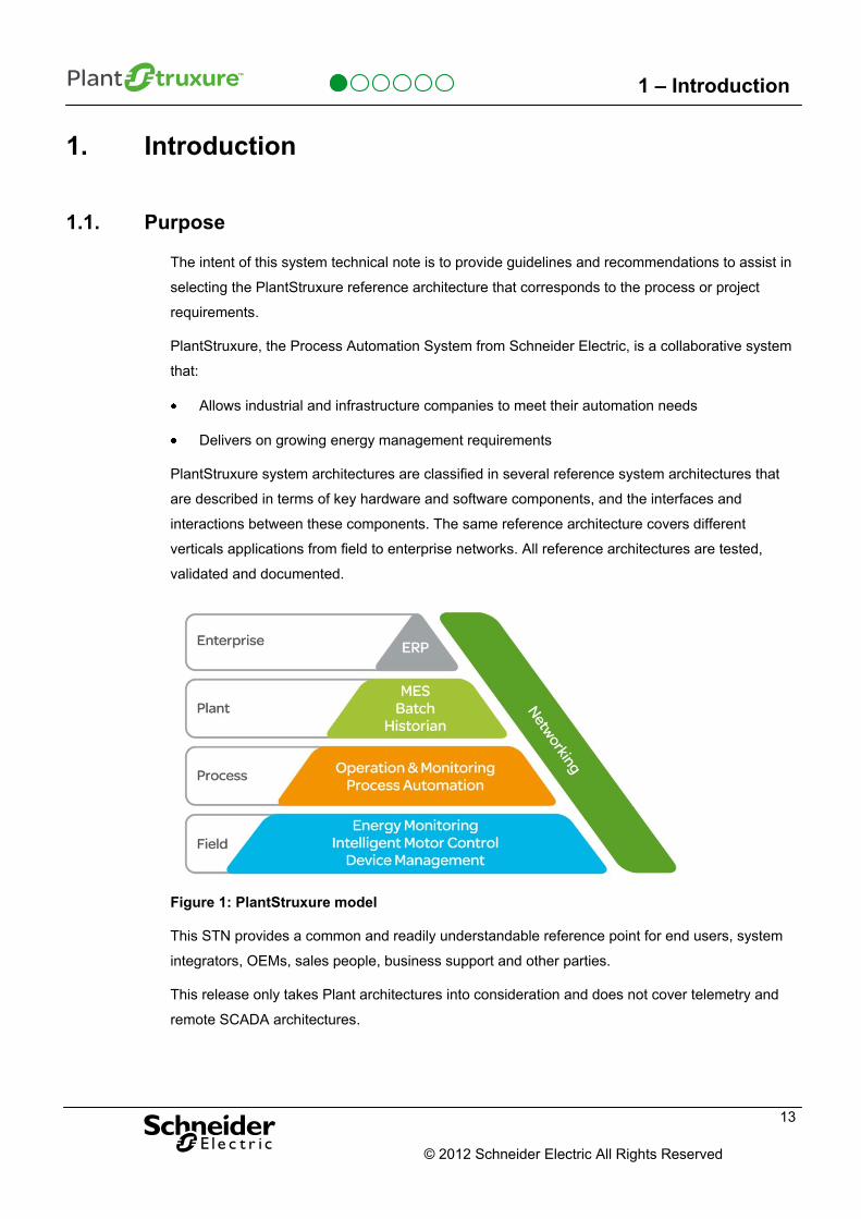
PlantStruxure system architectures are classified in several reference system architectures that
are described in terms of key hardware and software components, and the interfaces and
interactions between these components. The same reference architecture covers different
verticals applications from field to enterprise networks. All reference architectures are tested,
validated and documented.
Figure 1: PlantStruxure model
This STN provides a common and readily understandable reference point for end users, system
integrators, OEMs, sales people, business support and other parties.
This release only takes Plant architectures into consideration and does not cover telemetry and
remote SCADA architectures.
1 – Introduction
© 2012 Schneider Electric All Rights Reserved
14
1.2. Customer challenges
For sales and pre-sales forces, the main objective is to provide guidance about the features and
size of a system. The goals are:
To convince customers
To influence consultants for suitable solutions
The main objective of the SAE is to reuse a documented reference architecture to control the
limits of the system.
For Engineering (internal or system integrator) the goal is to:
Provide a system benchmark to guide design and implementation
Reuse a pre-defined architecture and therefore reduce engineering time
1.3. PlantStruxure architecture overview
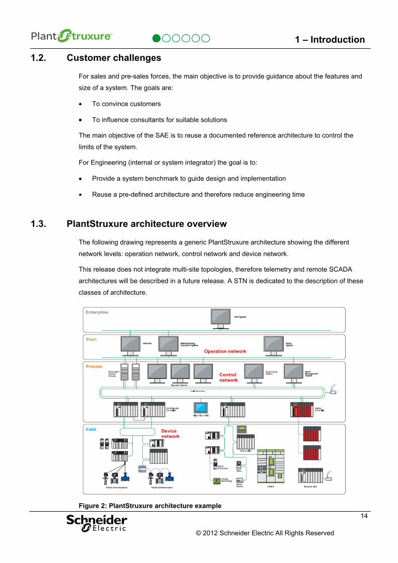
The following drawing represents a generic PlantStruxure architecture showing the different
network levels: operation network, control network and device network.
This release does not integrate multi-site topologies, therefore telemetry and remote SCADA
architectures will be described in a future release. A STN is dedicated to the description of these
classes of architecture.
Figure 2: PlantStruxure architecture example
Operation network
Control network
Devicenetwork
1 – Introduction
© 2012 Schneider Electric All Rights Reserved
15
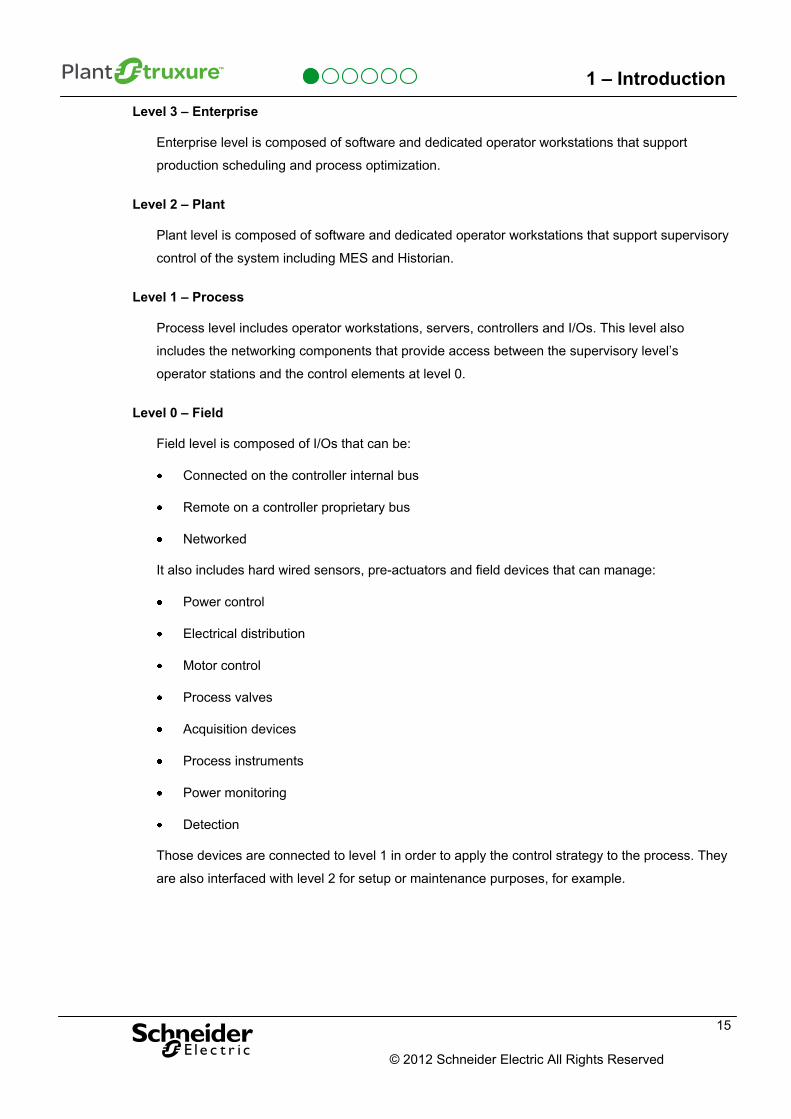
Level 3 – Enterprise
Enterprise level is composed of software and dedicated operator workstations that support
production scheduling and process optimization.
Level 2 – Plant
Plant level is composed of software and dedicated operator workstations that support supervisory
control of the system including MES and Historian.
Level 1 – Process
Process level includes operator workstations, servers, controllers and I/Os. This level also
includes the networking components that provide access between the supervisory level’s
operator stations and the control elements at level 0.
Level 0 – Field
Field level is composed of I/Os that can be:
Connected on the controller internal bus
Remote on a controller proprietary bus
Networked
It also includes hard wired sensors, pre-actuators and field devices that can manage:
Power control
Electrical distribution
Motor control
Process valves
Acquisition devices
Process instruments
Power monitoring
Detection
Those devices are connected to level 1 in order to apply the control strategy to the process. They
are also interfaced with level 2 for setup or maintenance purposes, for example.
1 – Introduction
© 2012 Schneider Electric All Rights Reserved
16
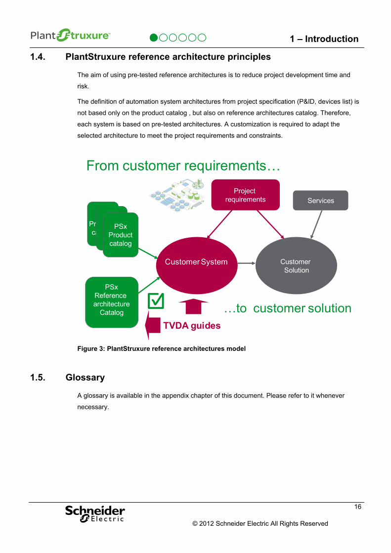
1.4. PlantStruxure reference architecture principles
The aim of using pre-tested reference architectures is to reduce project development time and
risk.
The definition of automation system architectures from project specification (P&ID, devices list) is
not based only on the product catalog , but also on reference architectures catalog. Therefore,
each system is based on pre-tested architectures. A customization is required to adapt the
selected architecture to meet the project requirements and constraints.
Figure 3: PlantStruxure reference architectures model
1.5. Glossary
A glossary is available in the appendix chapter of this document. Please refer to it whenever
necessary.
From customer requirements…
PsX
Products
catalog
Project
requirements
Customer System
Services
Customer
Solution
…to customer solution
PSx
Product
catalog
PSx
Reference
architecture
Catalog
TVDA guides
2 – Selection
© 2012 Schneider Electric All Rights Reserved
17
2. Selection
2.1. Reference architecture description
PlantStruxure automation system provides a solution for process applications such as water
plant, cement plant, mining plant, or food and beverage plant.
Customers’ systems are designed using reference architectures. Some are designed for the
overall control systems and some are designed for more specific elements such as the control
room or the functional units.
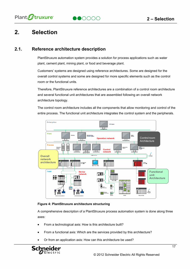
Therefore, PlantStruxure reference architectures are a combination of a control room architecture
and several functional unit architectures that are assembled following an overall network
architecture topology.
The control room architecture includes all the components that allow monitoring and control of the
entire process. The functional unit architecture integrates the control system and the peripherals.
Figure 4: PlantStruxure architecture structuring
A comprehensive description of a PlantStruxure process automation system is done along three
axes:
From a technological axis: How is this architecture built?
From a functional axis: Which are the services provided by this architecture?
Or from an application axis: How can this architecture be used?
Control roomArchitecture
Functional
unitArchitecture
Overallnetworkarchitecture
Operation network
Control network
Devicenetwork
2 – Selection
© 2012 Schneider Electric All Rights Reserved
18
2.2. PlantStruxure technological axis
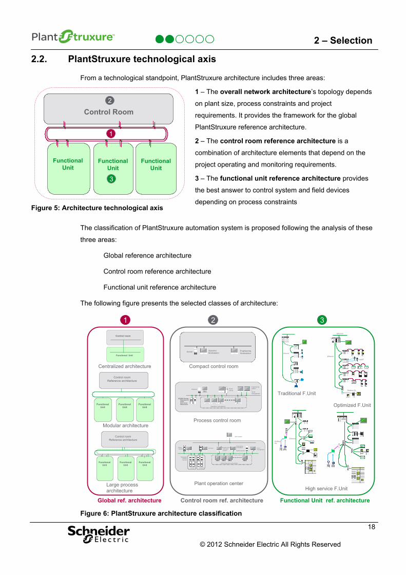
From a technological standpoint, PlantStruxure architecture includes three areas:
Figure 5: Architecture technological axis
1 – The overall network architecture’s topology depends
on plant size, process constraints and project
requirements. It provides the framework for the global
PlantStruxure reference architecture.
2 – The control room reference architecture is a
combination of architecture elements that depend on the
project operating and monitoring requirements.
3 – The functional unit reference architecture provides
the best answer to control system and field devices
depending on process constraints
The classification of PlantStruxure automation system is proposed following the analysis of these
three areas:
Global reference architecture
Control room reference architecture
Functional unit reference architecture
The following figure presents the selected classes of architecture:
Figure 6: PlantStruxure architecture classification
Control Room
Functional
UnitFunctional
Unit
Functional
Unit
1
2
3
Control room
Reference architecture
Functional
Unit
Functional
Unit
Functional
Unit
Control room
Reference architecture
Functional
Unit
Functional
Unit
Functional
Unit
1 2 3
Global ref. architecture Control room ref. architecture Functional Unit ref. architecture
Optimized F.Unit
Traditional F.Unit
High service F.Unit
Centralized architecture
Modular architecture
Large process
architecture
Compact control room
Process control room
Plant operation center
Control room
Functional Unit
Engineering StationServers
Operator Clients
Engineering Workstation
ServerOperator Workstation
Engineering StationServers
Operator Clients
Engineering Workstation
ServerOperator Workstation
Engineering Station/Asset management
SCADA ServersRedundant I/O server,alarm servertrends server
SCADA ServersRedundant I/O server,alarm servertrends server
Operators workstations
Historian Batchserver
Engineering Workstation/System servers
Assetmanagement
RedundantSCADAServers
BatchSystem
HistorianManufacturing
ExecutionSystem
ERP System
Global Operators workstations
Cluster 1 Cluster 2
Ethernet
Ethernet
HART
Ethernet
Modbus SL
PAC
Ethernet
Profibus
PA
2 – Selection
© 2012 Schneider Electric All Rights Reserved
19
Three classes of global reference architecture are selected:
A centralized automation system that targets mainly small process installations
A modular automation system that covers various medium size applications that require a
distributed architecture
A large process automation system that answers to the most complex systems, offering a
high level of service
Three classes of control room reference architecture are selected:
Compact control room architecture to deliver a standalone SCADA system to monitor a
small installation
Process control room architecture to offer a multi-client and server architecture, with
Historian capabilities
Plant operation center architecture to answer to the most complex architectures with
several levels of server and process optimization
Three classes of functional unit are defined:
A traditional functional unit to propose a hardwired solution for small process or for a plant
with a low level of knowledge within the operation and maintenance teams
An optimized functional unit to deliver a distributed architecture with a cost driven solution
and with easy installation
A high service functional unit to offer a service driven architecture based on Ethernet
providing high level of device management, energy management, advanced process control
and so on
2 – Selection
© 2012 Schneider Electric All Rights Reserved
20
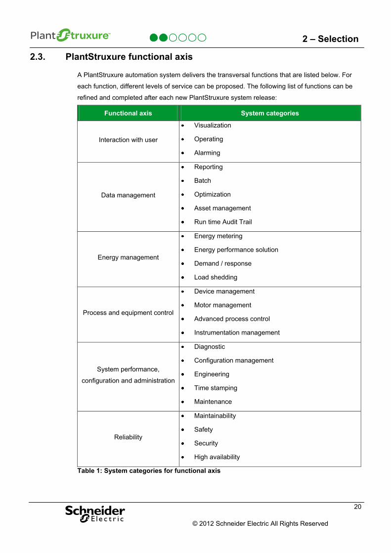
2.3. PlantStruxure functional axis
A PlantStruxure automation system delivers the transversal functions that are listed below. For
each function, different levels of service can be proposed. The following list of functions can be
refined and completed after each new PlantStruxure system release:
Functional axis System categories
Interaction with user
Visualization
Operating
Alarming
Data management
Reporting
Batch
Optimization
Asset management
Run time Audit Trail
Energy management
Energy metering
Energy performance solution
Demand / response
Load shedding
Process and equipment control
Device management
Motor management
Advanced process control
Instrumentation management
System performance,
configuration and administration
Diagnostic
Configuration management
Engineering
Time stamping
Maintenance
Reliability
Maintainability
Safety
Security
High availability
Table 1: System categories for functional axis
2 – Selection
© 2012 Schneider Electric All Rights Reserved
21
2.4. Application axis
PlantStruxure architecture is used in multiple segments such as mining, mineral and metal, water,
electrical energy, oil and gas, and food and beverage. Typical and validated architectures are
proposed for dedicated applications based on PlantStruxure reference architectures. Application
libraries are also delivered to reduce the development time and to improve the robustness of the
implementation.
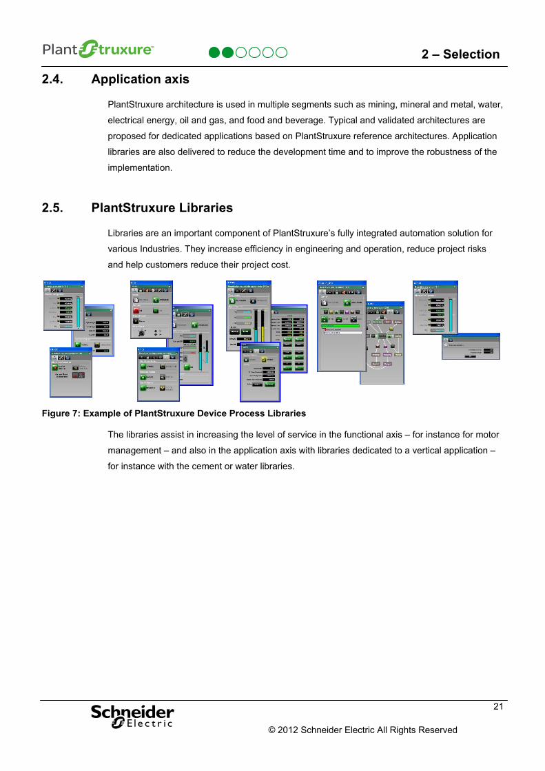
2.5. PlantStruxure Libraries
Libraries are an important component of PlantStruxure’s fully integrated automation solution for
various Industries. They increase efficiency in engineering and operation, reduce project risks
and help customers reduce their project cost.
Figure 7: Example of PlantStruxure Device Process Libraries
The libraries assist in increasing the level of service in the functional axis – for instance for motor
management – and also in the application axis with libraries dedicated to a vertical application –
for instance with the cement or water libraries.

2 – Selection
© 2012 Schneider Electric All Rights Reserved
22
3 – Global ref. archi.
© 2012 Schneider Electric All Rights Reserved
23
3. PlantStruxure global reference architecture
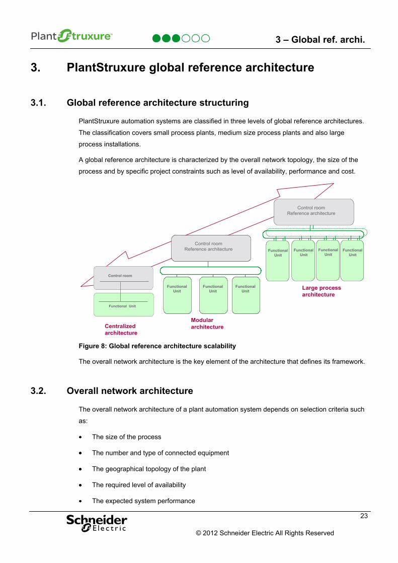
3.1. Global reference architecture structuring
PlantStruxure automation systems are classified in three levels of global reference architectures.
The classification covers small process plants, medium size process plants and also large
process installations.
A global reference architecture is characterized by the overall network topology, the size of the
process and by specific project constraints such as level of availability, performance and cost.
Figure 8: Global reference architecture scalability
The overall network architecture is the key element of the architecture that defines its framework.
3.2. Overall network architecture
The overall network architecture of a plant automation system depends on selection criteria such
as:
The size of the process
The number and type of connected equipment
The geographical topology of the plant
The required level of availability
The expected system performance
Control room
Reference architecture
Functional
Unit
Functional
Unit
Functional
Unit
Control room
Reference architecture
Functional
Unit
Functional
Unit
Functional
UnitFunctional
Unit
Centralized
architecture
Modular
architecture
Large process
architecture
Control room
Functional Unit
3 – Global ref. archi.
© 2012 Schneider Electric All Rights Reserved
24
Two types of plant network architecture are usually proposed and supported by PlantStruxure
networking system:
Flat network architecture: The plant, the control and the device networks are physically and
logically on the same network. This network architecture is a good fit for a compact or small
automation system. The centralized PlantStruxure reference architecture uses this type of
network.
Layered network architecture: It splits the topology into different levels. A separation between
the plant network, the control network and the field network is proposed in this case. This
network architecture is a good fit for a medium or large automation system and is covered by
PlantStruxure modular and large process reference architectures.
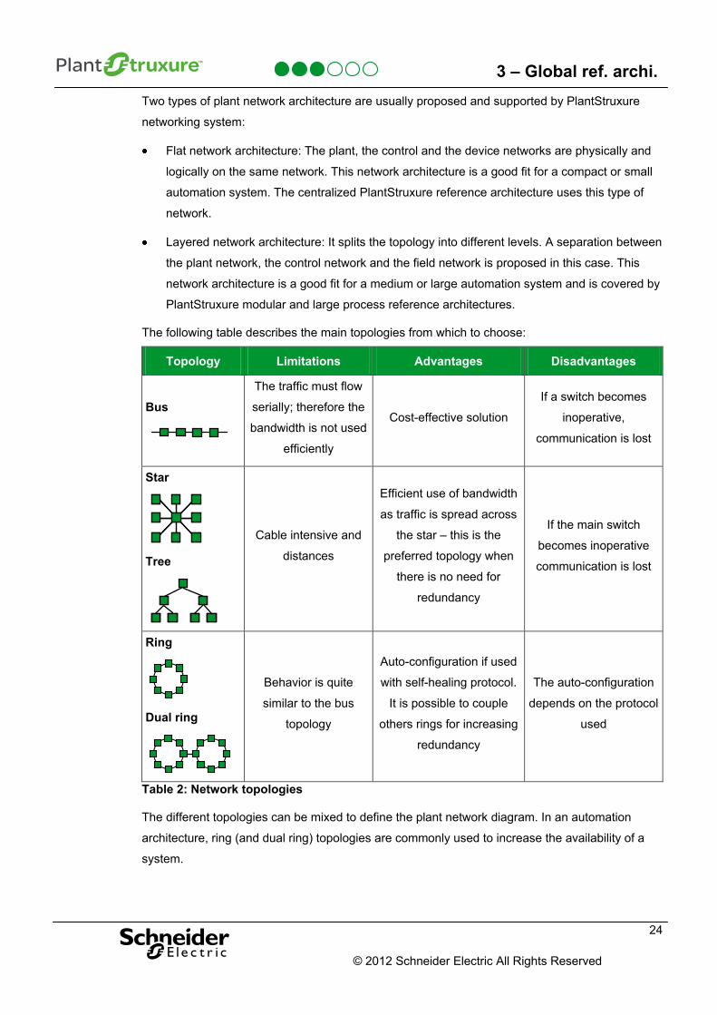
The following table describes the main topologies from which to choose:
Topology Limitations Advantages Disadvantages
Bus
The traffic must flow
serially; therefore the
bandwidth is not used
efficiently
Cost-effective solution
If a switch becomes
inoperative,
communication is lost
Star
Tree
Cable intensive and
distances
Efficient use of bandwidth
as traffic is spread across
the star – this is the
preferred topology when
there is no need for
redundancy
If the main switch
becomes inoperative
communication is lost
Ring
Dual ring
Behavior is quite
similar to the bus
topology
Auto-configuration if used
with self-healing protocol.
It is possible to couple
others rings for increasing
redundancy
The auto-configuration
depends on the protocol
used
Table 2: Network topologies
The different topologies can be mixed to define the plant network diagram. In an automation
architecture, ring (and dual ring) topologies are commonly used to increase the availability of a
system.
3 – Global ref. archi.
© 2012 Schneider Electric All Rights Reserved
25
3.3. PlantStruxure centralized architecture
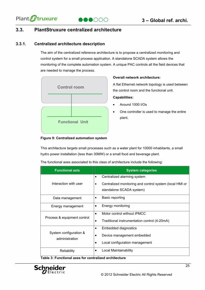
3.3.1. Centralized architecture description
The aim of the centralized reference architecture is to propose a centralized monitoring and
control system for a small process application. A standalone SCADA system allows the
monitoring of the complete automation system. A unique PAC controls all the field devices that
are needed to manage the process.
Figure 9: Centralized automation system
Overall network architecture:
A flat Ethernet network topology is used between
the control room and the functional unit.
Capabilities:
Around 1000 I/Os
One controller is used to manage the entire
plant.
This architecture targets small processes such as a water plant for 10000 inhabitants, a small
hydro power installation (less than 30MW) or a small food and beverage plant.
The functional axes associated to this class of architecture include the following:
Functional axis System categories
Interaction with user
Centralized alarming system
Centralized monitoring and control system (local HMI or
standalone SCADA system)
Data management Basic reporting
Energy management Energy monitoring
Process & equipment control Motor control without iPMCC
Traditional instrumentation control (4-20mA)
System configuration &
administration
Embedded diagnostics
Device management embedded
Local configuration management
Reliability Local Maintainability
Table 3: Functional axes for centralized architecture
Control room
Functional Unit
3 – Global ref. archi.
© 2012 Schneider Electric All Rights Reserved
26
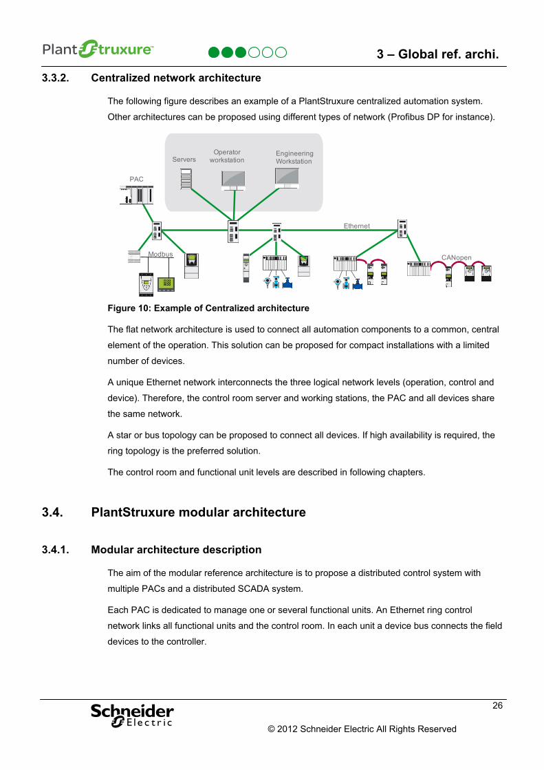
3.3.2. Centralized network architecture
The following figure describes an example of a PlantStruxure centralized automation system.
Other architectures can be proposed using different types of network (Profibus DP for instance).
Figure 10: Example of Centralized architecture
The flat network architecture is used to connect all automation components to a common, central
element of the operation. This solution can be proposed for compact installations with a limited
number of devices.
A unique Ethernet network interconnects the three logical network levels (operation, control and
device). Therefore, the control room server and working stations, the PAC and all devices share
the same network.
A star or bus topology can be proposed to connect all devices. If high availability is required, the
ring topology is the preferred solution.
The control room and functional unit levels are described in following chapters.
3.4. PlantStruxure modular architecture
3.4.1. Modular architecture description
The aim of the modular reference architecture is to propose a distributed control system with
multiple PACs and a distributed SCADA system.
Each PAC is dedicated to manage one or several functional units. An Ethernet ring control
network links all functional units and the control room. In each unit a device bus connects the field
devices to the controller.
Engineering WorkstationServers
Operator workstation
PAC
CANopen
Ethernet
Modbus
3 – Global ref. archi.
© 2012 Schneider Electric All Rights Reserved
27
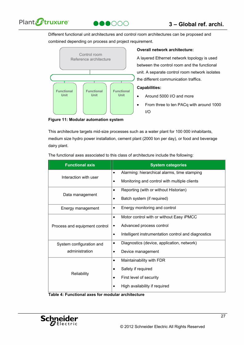
Different functional unit architectures and control room architectures can be proposed and
combined depending on process and project requirement.
Figure 11: Modular automation system
Overall network architecture:
A layered Ethernet network topology is used
between the control room and the functional
unit. A separate control room network isolates
the different communication traffics.
Capabilities:
Around 5000 I/O and more
From three to ten PACq with around 1000
I/O
This architecture targets mid-size processes such as a water plant for 100 000 inhabitants,
medium size hydro power installation, cement plant (2000 ton per day), or food and beverage
dairy plant.
The functional axes associated to this class of architecture include the following:
Functional axis System categories
Interaction with user Alarming: hierarchical alarms, time stamping
Monitoring and control with multiple clients
Data management Reporting (with or without Historian)
Batch system (if required)
Energy management Energy monitoring and control
Process and equipment control
Motor control with or without Easy iPMCC
Advanced process control
Intelligent instrumentation control and diagnostics
System configuration and
administration
Diagnostics (device, application, network)
Device management
Reliability
Maintainability with FDR
Safety if required
First level of security
High availability if required
Table 4: Functional axes for modular architecture
Control room
Reference architecture
Functional
Unit
Functional
Unit
Functional
Unit
3 – Global ref. archi.
© 2012 Schneider Electric All Rights Reserved
28
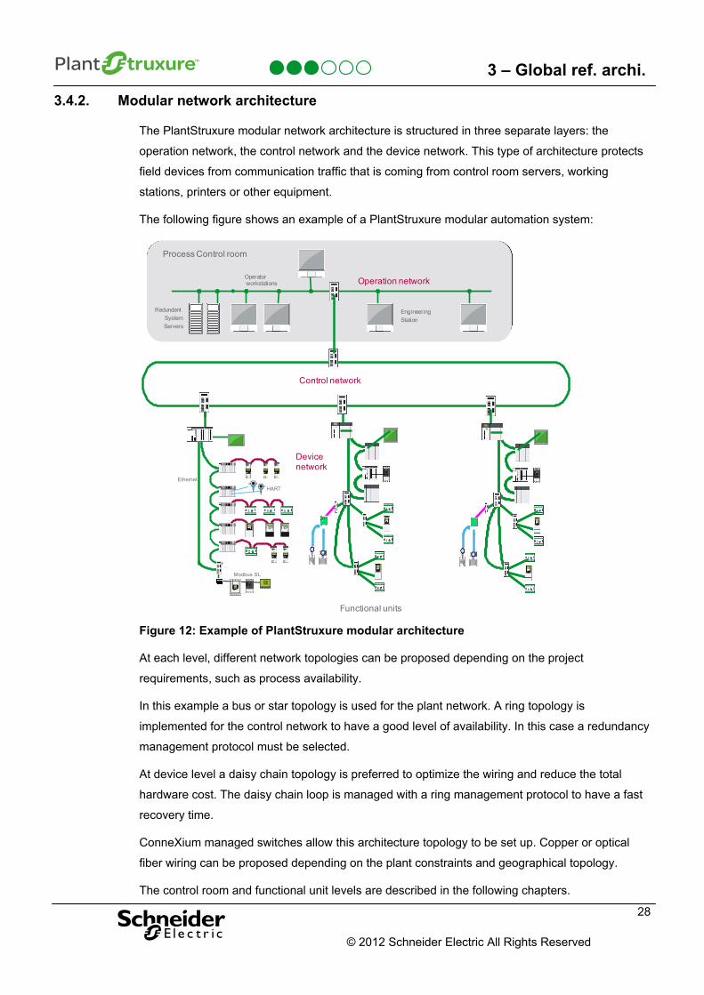
3.4.2. Modular network architecture
The PlantStruxure modular network architecture is structured in three separate layers: the
operation network, the control network and the device network. This type of architecture protects
field devices from communication traffic that is coming from control room servers, working
stations, printers or other equipment.
The following figure shows an example of a PlantStruxure modular automation system:
Figure 12: Example of PlantStruxure modular architecture
At each level, different network topologies can be proposed depending on the project
requirements, such as process availability.
In this example a bus or star topology is used for the plant network. A ring topology is
implemented for the control network to have a good level of availability. In this case a redundancy
management protocol must be selected.
At device level a daisy chain topology is preferred to optimize the wiring and reduce the total
hardware cost. The daisy chain loop is managed with a ring management protocol to have a fast
recovery time.
ConneXium managed switches allow this architecture topology to be set up. Copper or optical
fiber wiring can be proposed depending on the plant constraints and geographical topology.
The control room and functional unit levels are described in the following chapters.
Engineering
Station
Redundant
System
Servers
H is tor ian
Engineering
Station
Redundant
System
Servers
Process Control room
Control network
Devicenetwork
Operation network Operatorworkstations
Functional units
Ethernet
HART
Modbus SL
3 – Global ref. archi.
© 2012 Schneider Electric All Rights Reserved
29
3.5. PlantStruxure large process architecture
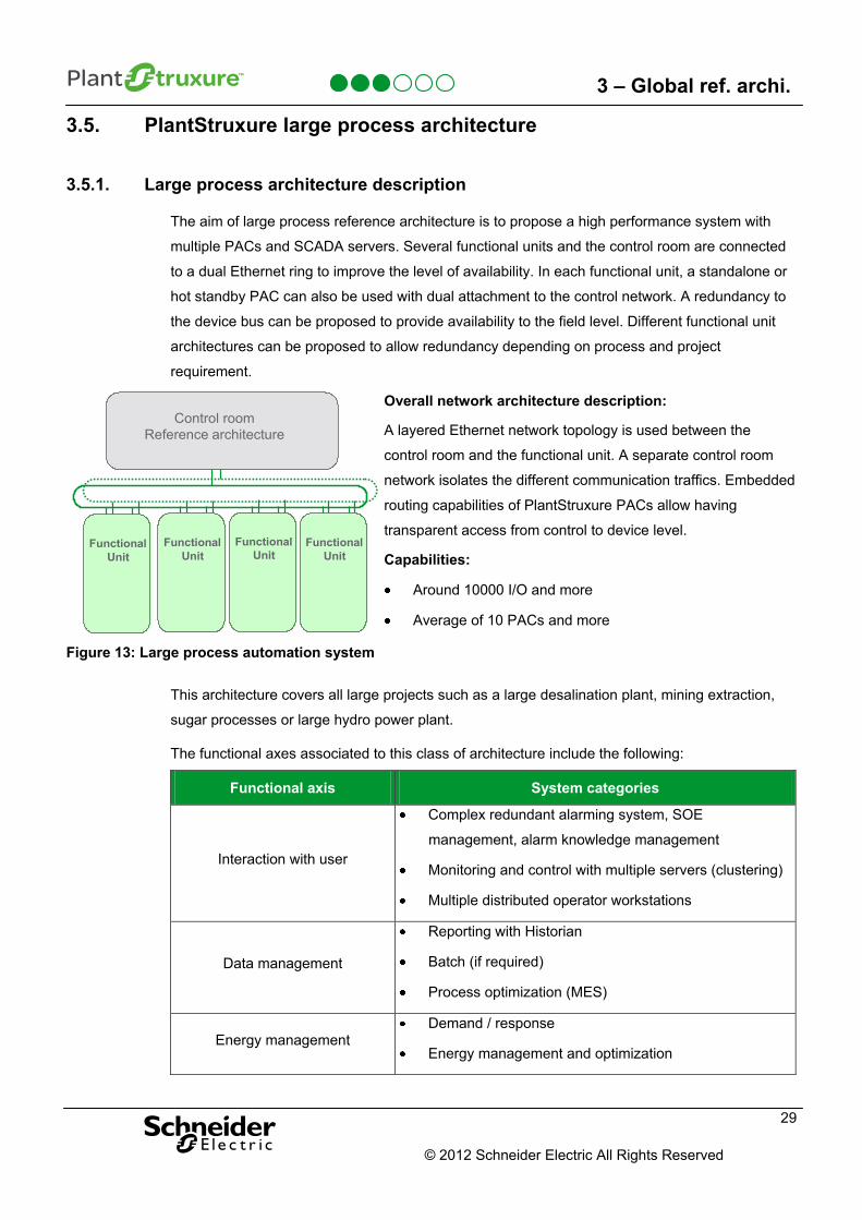
3.5.1. Large process architecture description
The aim of large process reference architecture is to propose a high performance system with
multiple PACs and SCADA servers. Several functional units and the control room are connected
to a dual Ethernet ring to improve the level of availability. In each functional unit, a standalone or
hot standby PAC can also be used with dual attachment to the control network. A redundancy to
the device bus can be proposed to provide availability to the field level. Different functional unit
architectures can be proposed to allow redundancy depending on process and project
requirement.
Figure 13: Large process automation system
Overall network architecture description:
A layered Ethernet network topology is used between the
control room and the functional unit. A separate control room
network isolates the different communication traffics. Embedded
routing capabilities of PlantStruxure PACs allow having
transparent access from control to device level.
Capabilities:
Around 10000 I/O and more
Average of 10 PACs and more
This architecture covers all large projects such as a large desalination plant, mining extraction,
sugar processes or large hydro power plant.
The functional axes associated to this class of architecture include the following:
Functional axis System categories
Interaction with user
Complex redundant alarming system, SOE
management, alarm knowledge management
Monitoring and control with multiple servers (clustering)
Multiple distributed operator workstations
Data management
Reporting with Historian
Batch (if required)
Process optimization (MES)
Energy management Demand / response
Energy management and optimization
Control room
Reference architecture
Functional
Unit
Functional
Unit
Functional
UnitFunctional
Unit
3 – Global ref. archi.
© 2012 Schneider Electric All Rights Reserved
30
Functional axis System categories
Process and equipment control
Motor control with high dependability iPMCC
Advanced process control
Intelligent instrumentation
System configuration and
administration
Maintainability with FDR
Full diagnostics (application, network and device)
Tool-based device management
Configuration management
Reliability
Safety if required
High availability
Secure control room and functional unit
Table 5: Functional axis for large process architecture
3.5.2. Large process network architecture
The large process network architecture is the same as the PlantStruxure modular architecture;
three separate network layers structure the plant network diagram.
A large process automation system often requires a highly available solution at all levels of the
architecture.
The system architecture drawn below shows the various layers where redundancy capabilities
are proposed:
At the plant level, which includes redundancy of multiple SCADA servers and operator
clients, as well as redundancy of network interfaces
At the control network level, which includes dual ring capabilities using an effective
redundancy management protocol
At the functional unit level, which includes redundancy of the control system and the field
network
3 – Global ref. archi.
© 2012 Schneider Electric All Rights Reserved
31
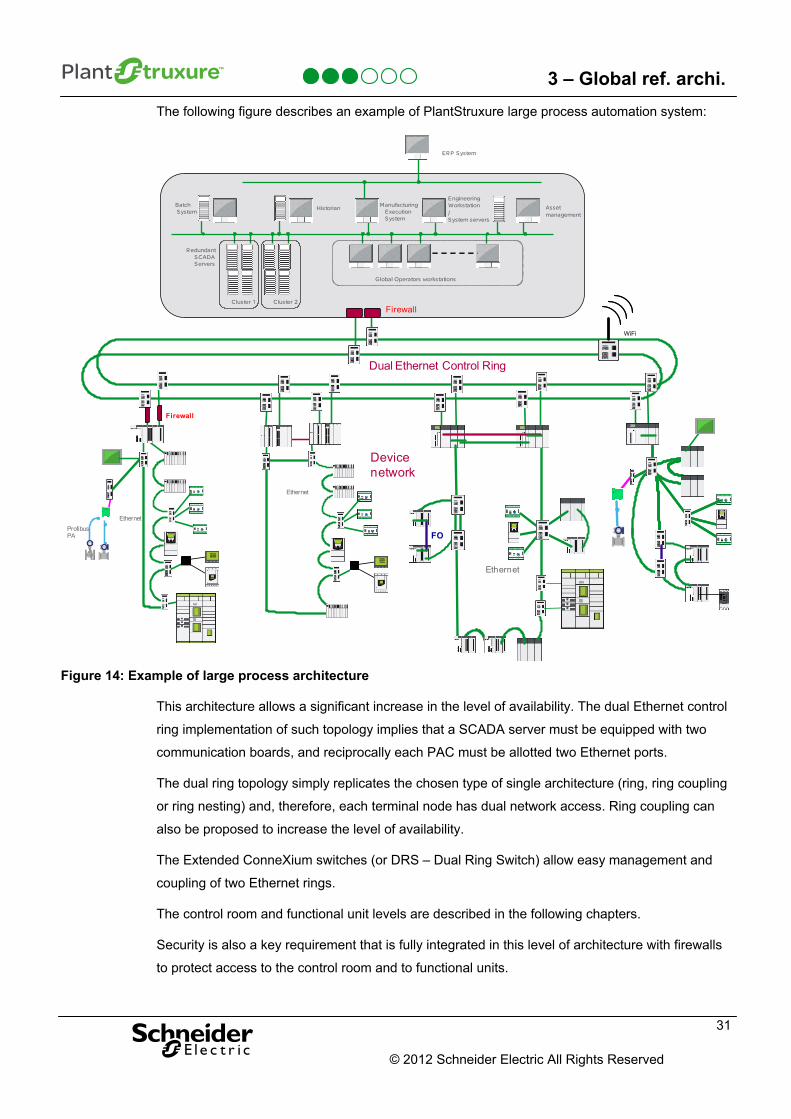
The following figure describes an example of PlantStruxure large process automation system:
Figure 14: Example of large process architecture
This architecture allows a significant increase in the level of availability. The dual Ethernet control
ring implementation of such topology implies that a SCADA server must be equipped with two
communication boards, and reciprocally each PAC must be allotted two Ethernet ports.
The dual ring topology simply replicates the chosen type of single architecture (ring, ring coupling
or ring nesting) and, therefore, each terminal node has dual network access. Ring coupling can
also be proposed to increase the level of availability.
The Extended ConneXium switches (or DRS – Dual Ring Switch) allow easy management and
coupling of two Ethernet rings.
The control room and functional unit levels are described in the following chapters.
Security is also a key requirement that is fully integrated in this level of architecture with firewalls
to protect access to the control room and to functional units.
Dual Ethernet Control Ring
Device
network
WiFi
Firewall
PACPAC
FO
Ethernet
PAC
Ethernet
Engineering Workstation/System servers
Assetmanagement
RedundantSCADAServers
BatchSystem
HistorianManufacturing
ExecutionSystem
ERP System
Global Operators workstations
Cluster 1 Cluster 2
Firewall
PAC
Ethernet
ProfibusPA
3 – Global ref. archi.
© 2012 Schneider Electric All Rights Reserved
32
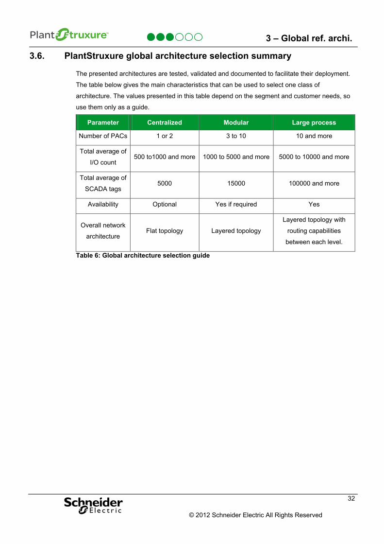
3.6. PlantStruxure global architecture selection summary
The presented architectures are tested, validated and documented to facilitate their deployment.
The table below gives the main characteristics that can be used to select one class of
architecture. The values presented in this table depend on the segment and customer needs, so
use them only as a guide.
Parameter Centralized Modular Large process
Number of PACs 1 or 2 3 to 10 10 and more
Total average of
I/O count 500 to1000 and more 1000 to 5000 and more 5000 to 10000 and more
Total average of
SCADA tags 5000 15000 100000 and more
Availability Optional Yes if required Yes
Overall network
architecture Flat topology Layered topology
Layered topology with
routing capabilities
between each level.
Table 6: Global architecture selection guide
4 – Control room ref. archi.
© 2012 Schneider Electric All Rights Reserved
33
4. Control room reference architectures
4.1. Control room architecture structuring
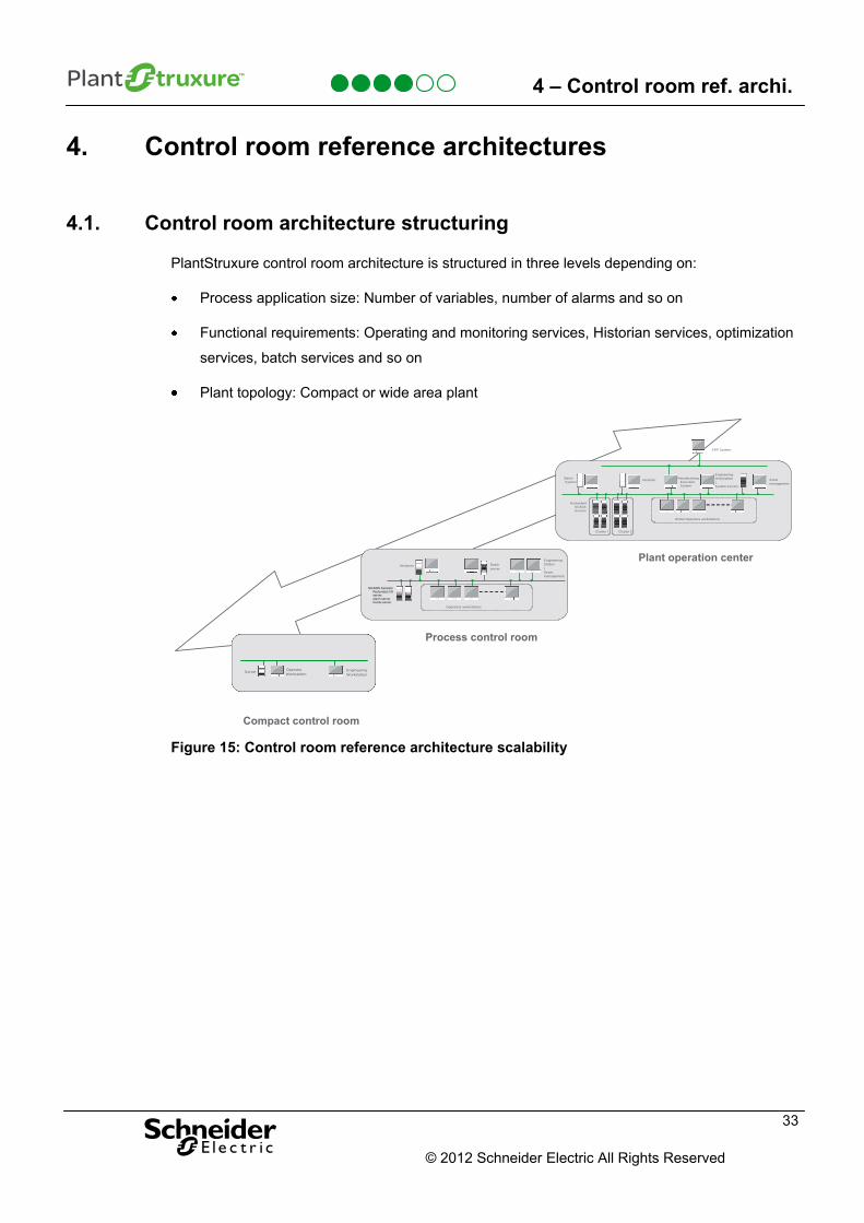
PlantStruxure control room architecture is structured in three levels depending on:
Process application size: Number of variables, number of alarms and so on
Functional requirements: Operating and monitoring services, Historian services, optimization
services, batch services and so on
Plant topology: Compact or wide area plant
Figure 15: Control room reference architecture scalability
Compact control room
Process control room
Plant operation center
Engineering StationServers
Operator Clients
Engineering Workstation
ServerOperator Workstation
Engineering StationServers
Operator Clients
Engineering Workstation
ServerOperator Workstation
Engineering Station/Asset management
SCADA ServersRedundant I/O server,alarm servertrends server
SCADA ServersRedundant I/O server,alarm servertrends server
Operators workstations
Historian Batchserver
Engineering Workstation/System servers
Assetmanagement
RedundantSCADAServers
BatchSystem
HistorianManufacturing
ExecutionSystem
ERP System
Global Operators workstations
Cluster 1 Cluster 2
4 – Control room ref. archi.
© 2012 Schneider Electric All Rights Reserved
34
4.2. PlantStruxure compact control room
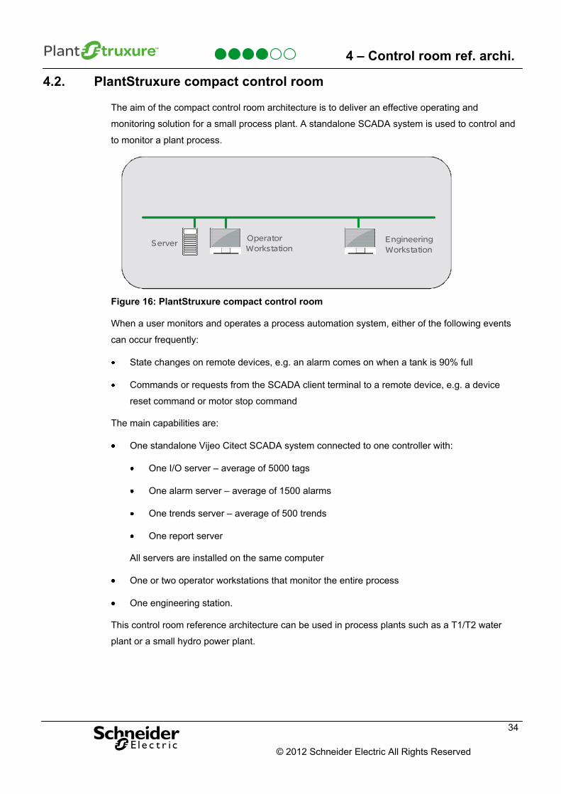
The aim of the compact control room architecture is to deliver an effective operating and
monitoring solution for a small process plant. A standalone SCADA system is used to control and
to monitor a plant process.
Figure 16: PlantStruxure compact control room
When a user monitors and operates a process automation system, either of the following events
can occur frequently:
State changes on remote devices, e.g. an alarm comes on when a tank is 90% full
Commands or requests from the SCADA client terminal to a remote device, e.g. a device
reset command or motor stop command
The main capabilities are:
One standalone Vijeo Citect SCADA system connected to one controller with:
One I/O server – average of 5000 tags
One alarm server – average of 1500 alarms
One trends server – average of 500 trends
One report server
All servers are installed on the same computer
One or two operator workstations that monitor the entire process
One engineering station.
This control room reference architecture can be used in process plants such as a T1/T2 water
plant or a small hydro power plant.
Engineering StationServers
Operator Clients
Engineering Workstation
ServerOperator Workstation
Engineering StationServers
Operator Clients
Engineering Workstation
ServerOperator Workstation
4 – Control room ref. archi.
© 2012 Schneider Electric All Rights Reserved
35
4.3. PlantStruxure process control room
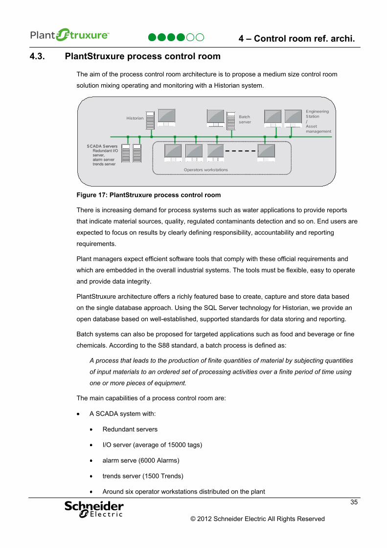
The aim of the process control room architecture is to propose a medium size control room
solution mixing operating and monitoring with a Historian system.
Figure 17: PlantStruxure process control room
There is increasing demand for process systems such as water applications to provide reports
that indicate material sources, quality, regulated contaminants detection and so on. End users are
expected to focus on results by clearly defining responsibility, accountability and reporting
requirements.
Plant managers expect efficient software tools that comply with these official requirements and
which are embedded in the overall industrial systems. The tools must be flexible, easy to operate
and provide data integrity.
PlantStruxure architecture offers a richly featured base to create, capture and store data based
on the single database approach. Using the SQL Server technology for Historian, we provide an
open database based on well-established, supported standards for data storing and reporting.
Batch systems can also be proposed for targeted applications such as food and beverage or fine
chemicals. According to the S88 standard, a batch process is defined as:
A process that leads to the production of finite quantities of material by subjecting quantities
of input materials to an ordered set of processing activities over a finite period of time using
one or more pieces of equipment.
The main capabilities of a process control room are:
A SCADA system with:
Redundant servers
I/O server (average of 15000 tags)
alarm serve (6000 Alarms)
trends server (1500 Trends)
Around six operator workstations distributed on the plant
Engineering Station/Asset management
SCADA ServersRedundant I/O server,alarm servertrends server
SCADA ServersRedundant I/O server,alarm servertrends server
Operators workstations
Historian Batchserver
4 – Control room ref. archi.
© 2012 Schneider Electric All Rights Reserved
36
Historian server
Batch server (if required, e.g. food and beverage)
Asset management
From three to five PACs
Engineering stations with multiple workstations
CNM (ConneXium Network Management)
This control room reference architecture can be used in mid-size process applications such as a
T3 water application, C2 cement plant or medium size mining plant.
4.4. PlantStruxure plant operation center
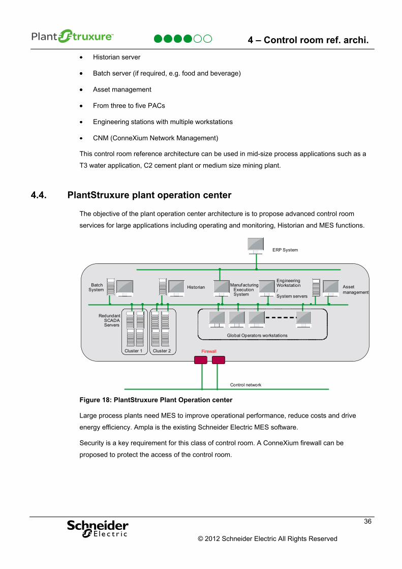
The objective of the plant operation center architecture is to propose advanced control room
services for large applications including operating and monitoring, Historian and MES functions.
Figure 18: PlantStruxure Plant Operation center
Large process plants need MES to improve operational performance, reduce costs and drive
energy efficiency. Ampla is the existing Schneider Electric MES software.
Security is a key requirement for this class of control room. A ConneXium firewall can be
proposed to protect the access of the control room.
Engineering Workstation
/
System servers
Asset
management
RedundantSCADAServers
BatchSystem
HistorianManufacturing
ExecutionSystem
ERP System
Global Operators workstations
Cluster 1 Cluster 2
Control network
Firewall
4 – Control room ref. archi.
© 2012 Schneider Electric All Rights Reserved
37
The main capabilities of the plant operation center include:
SCADA system with:
Redundant servers with clustering
Several I/O servers (average of 100000 and more)
Several alarm servers (15000 alarms and more)
Several trends servers (5000 trends and more)
More than six operator workstations distributed on the plant
Historian server
MES with Ampla
Batch server (if required, e.g. for food and beverage)
Asset management
Configuration server
Firewall
Potential link to business system
Optional backup control room
From five to ten PACs and more
Multiple engineering workstations
CNM (ConneXium network management)
This control room reference architecture can be used in large and complex process applications
such as oil and gas, desalination plants or large mining installations.
4 – Control room ref. archi.
© 2012 Schneider Electric All Rights Reserved
38
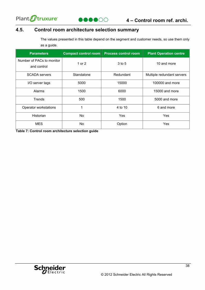
4.5. Control room architecture selection summary
The values presented in this table depend on the segment and customer needs, so use them only
as a guide.
Parameters Compact control room Process control room Plant Operation centre
Number of PACs to monitor
and control 1 or 2 3 to 5 10 and more
SCADA servers Standalone Redundant Multiple redundant servers
I/O server tags 5000 15000 100000 and more
Alarms 1500 6000 15000 and more
Trends 500 1500 5000 and more
Operator workstations 1 4 to 10 6 and more
Historian No Yes Yes
MES No Option Yes
Table 7: Control room architecture selection guide
5 – Func. unit ref. archi.
© 2012 Schneider Electric All Rights Reserved
39
5. Functional unit reference architectures
5.1. Functional unit architecture structuring
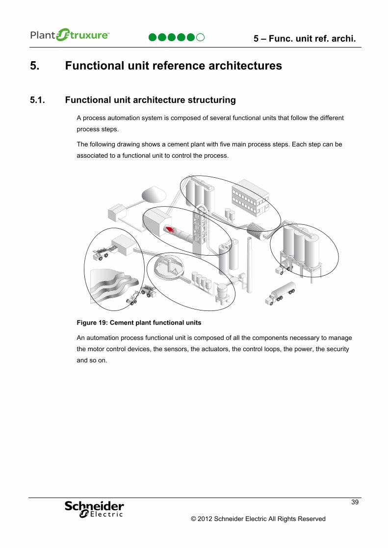
A process automation system is composed of several functional units that follow the different
process steps.
The following drawing shows a cement plant with five main process steps. Each step can be
associated to a functional unit to control the process.
Figure 19: Cement plant functional units
An automation process functional unit is composed of all the components necessary to manage
the motor control devices, the sensors, the actuators, the control loops, the power, the security
and so on.
5 – Func. unit ref. archi.
© 2012 Schneider Electric All Rights Reserved
40
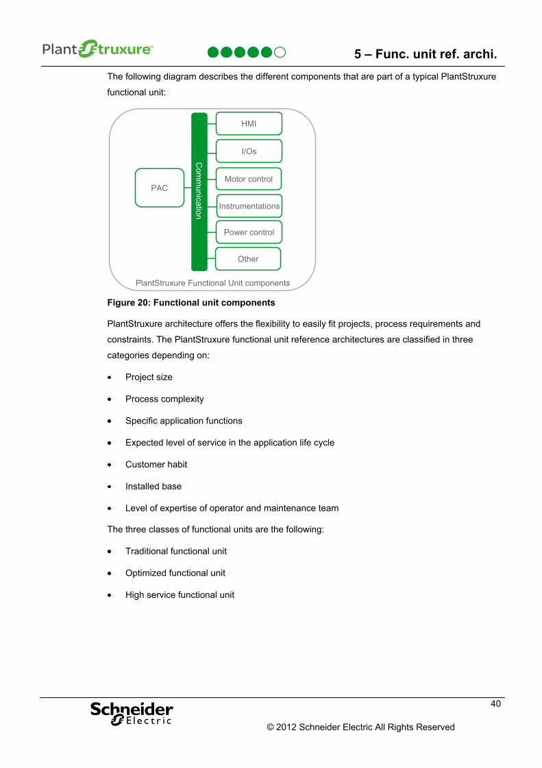
The following diagram describes the different components that are part of a typical PlantStruxure
functional unit:
Figure 20: Functional unit components
PlantStruxure architecture offers the flexibility to easily fit projects, process requirements and
constraints. The PlantStruxure functional unit reference architectures are classified in three
categories depending on:
Project size
Process complexity
Specific application functions
Expected level of service in the application life cycle
Customer habit
Installed base
Level of expertise of operator and maintenance team
The three classes of functional units are the following:
Traditional functional unit
Optimized functional unit
High service functional unit
Com
munic
atio
n
I/Os
Motor control
Instrumentations
Power control
Other
PAC
HMI
PlantStruxure Functional Unit components
5 – Func. unit ref. archi.
© 2012 Schneider Electric All Rights Reserved
41
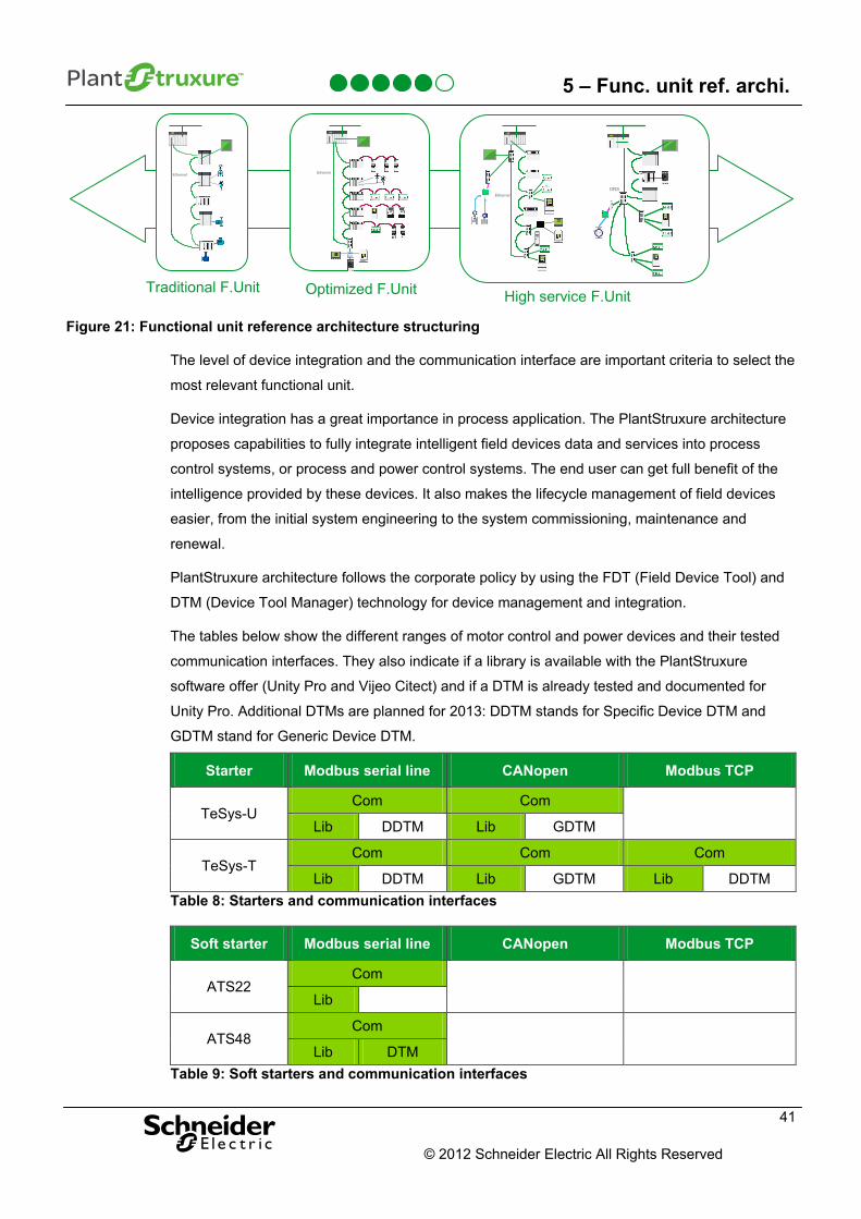
Figure 21: Functional unit reference architecture structuring
The level of device integration and the communication interface are important criteria to select the
most relevant functional unit.
Device integration has a great importance in process application. The PlantStruxure architecture
proposes capabilities to fully integrate intelligent field devices data and services into process
control systems, or process and power control systems. The end user can get full benefit of the
intelligence provided by these devices. It also makes the lifecycle management of field devices
easier, from the initial system engineering to the system commissioning, maintenance and
renewal.
PlantStruxure architecture follows the corporate policy by using the FDT (Field Device Tool) and
DTM (Device Tool Manager) technology for device management and integration.
The tables below show the different ranges of motor control and power devices and their tested
communication interfaces. They also indicate if a library is available with the PlantStruxure
software offer (Unity Pro and Vijeo Citect) and if a DTM is already tested and documented for
Unity Pro. Additional DTMs are planned for 2013: DDTM stands for Specific Device DTM and
GDTM stand for Generic Device DTM.
Starter Modbus serial line CANopen Modbus TCP
TeSys-U Com Com
Lib DDTM Lib GDTM
TeSys-T Com Com Com
Lib DDTM Lib GDTM Lib DDTM
Table 8: Starters and communication interfaces
Soft starter Modbus serial line CANopen Modbus TCP
ATS22 Com
Lib
ATS48 Com
Lib DTM
Table 9: Soft starters and communication interfaces
Optimized F.UnitTraditional F.UnitHigh service F.Unit
EthernetEthernet
PAC
Ethernet
DRS
5 – Func. unit ref. archi.
© 2012 Schneider Electric All Rights Reserved
42
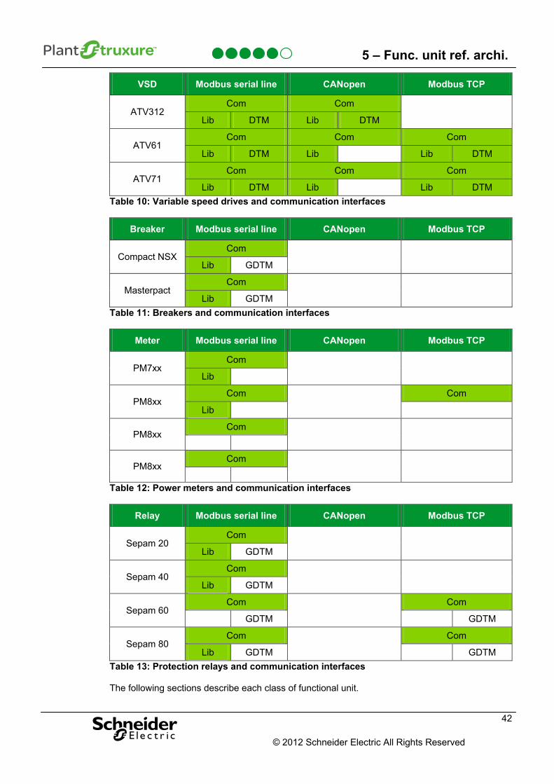
VSD Modbus serial line CANopen Modbus TCP
ATV312 Com Com
Lib DTM Lib DTM
ATV61 Com Com Com
Lib DTM Lib
Lib DTM
ATV71 Com Com Com
Lib DTM Lib
Lib DTM
Table 10: Variable speed drives and communication interfaces
Breaker Modbus serial line CANopen Modbus TCP
Compact NSX Com
Lib GDTM
Masterpact Com
Lib GDTM
Table 11: Breakers and communication interfaces
Meter Modbus serial line CANopen Modbus TCP
PM7xx Com
Lib
PM8xx Com
Com
Lib
PM8xx Com
PM8xx Com
Table 12: Power meters and communication interfaces
Relay Modbus serial line CANopen Modbus TCP
Sepam 20 Com
Lib GDTM
Sepam 40 Com
Lib GDTM
Sepam 60 Com
Com
GDTM
GDTM
Sepam 80 Com
Com
Lib GDTM
GDTM
Table 13: Protection relays and communication interfaces
The following sections describe each class of functional unit.
5 – Func. unit ref. archi.
© 2012 Schneider Electric All Rights Reserved
43
5.2. PlantStruxure traditional functional unit
5.2.1. Functional unit description
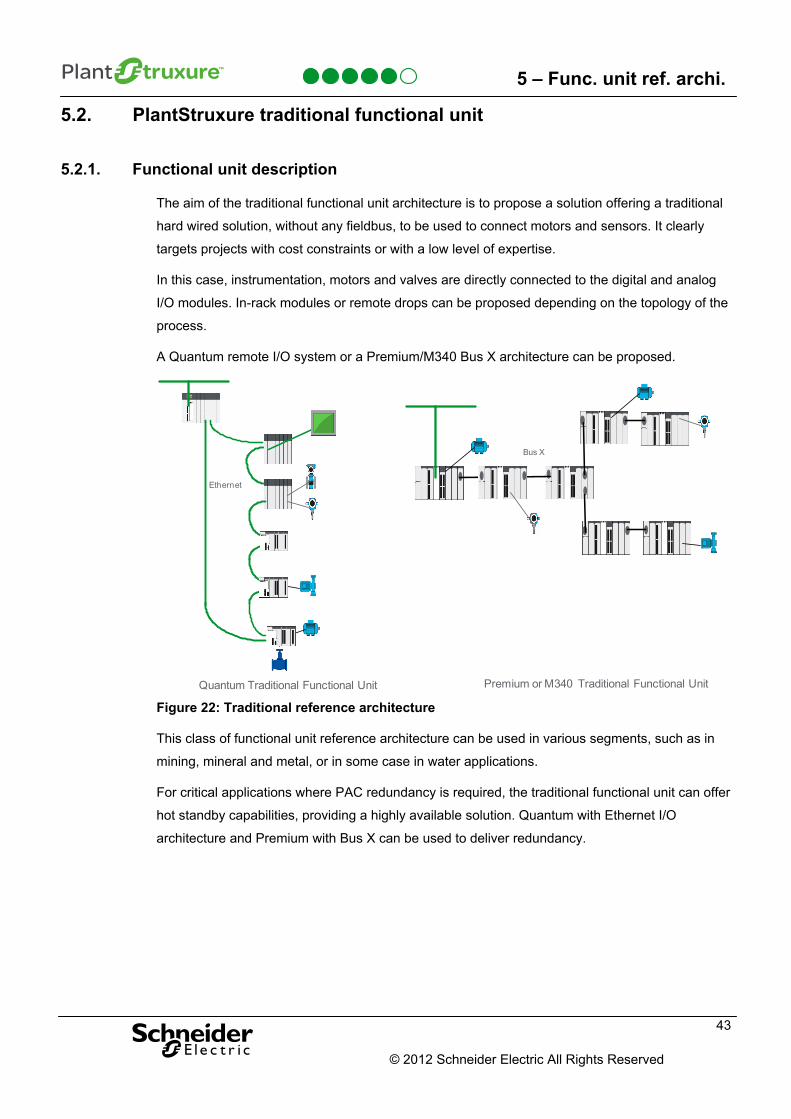
The aim of the traditional functional unit architecture is to propose a solution offering a traditional
hard wired solution, without any fieldbus, to be used to connect motors and sensors. It clearly
targets projects with cost constraints or with a low level of expertise.
In this case, instrumentation, motors and valves are directly connected to the digital and analog
I/O modules. In-rack modules or remote drops can be proposed depending on the topology of the
process.
A Quantum remote I/O system or a Premium/M340 Bus X architecture can be proposed.
Figure 22: Traditional reference architecture
This class of functional unit reference architecture can be used in various segments, such as in
mining, mineral and metal, or in some case in water applications.
For critical applications where PAC redundancy is required, the traditional functional unit can offer
hot standby capabilities, providing a highly available solution. Quantum with Ethernet I/O
architecture and Premium with Bus X can be used to deliver redundancy.
Ethernet
Quantum Traditional Functional Unit Premium or M340 Traditional Functional Unit
Bus X
5 – Func. unit ref. archi.
© 2012 Schneider Electric All Rights Reserved
44
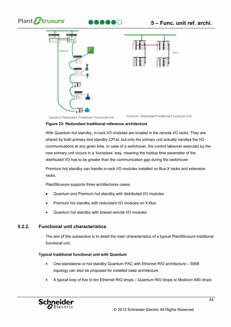
Figure 23: Redundant traditional reference architecture
With Quantum hot standby, in-rack I/O modules are located in the remote I/O racks. They are
shared by both primary and standby CPUs, but only the primary unit actually handles the I/O
communications at any given time. In case of a switchover, the control takeover executed by the
new primary unit occurs in a ‘bumpless’ way, meaning the holdup time parameter of the
distributed I/O has to be greater than the communication gap during the switchover.
Premium hot standby can handle in-rack I/O modules installed on Bus-X racks and extension
racks.
PlantStruxure supports three architectures cases:
Quantum and Premium hot standby with distributed I/O modules
Premium hot standby with redundant I/O modules on X-Bus
Quantum hot standby with shared remote I/O modules
5.2.2. Functional unit characteristics
The aim of this subsection is to detail the main characteristics of a typical PlantStruxure traditional
functional unit.
Typical traditional functional unit with Quantum
One standalone or hot standby Quantum PAC with Ethernet RIO architecture – S908
topology can also be proposed for installed base architecture
A typical loop of five to ten Ethernet RIO drops – Quantum RIO drops or Modicon X80 drops
Ethernet
Quantum Redundant Traditional Functional Unit Premium RedundantTraditional Functional Unit
Bus X
5 – Func. unit ref. archi.
© 2012 Schneider Electric All Rights Reserved
45
Total of 1000 I/O -1500 I/O:
256 I/O per drop
70% digital / 30% analog ( 4-20mA)
Option : ERT module for time stamping
Direct wiring for motor management and for instrumentation
Optionally a local HMI connected to one CRA drop or connected to the control network
Traditional functional unit with Premium
One standalone or hot standby Premium PAC with extended Bus-X racks
A typical configuration with five to six racks
Total of 600 I/O -1000 I/O
70% digital / 30% analog ( 4-20mA)
Direct wiring for motor management and for instrumentation
Traditional functional unit with Modicon M340 PAC
One standalone M340 PAC with extended Bus-X racks
A typical configuration with one to three racks
Total of 300 I/O -600 I/O
70% digital / 30% analog ( 4-20mA)
Direct wiring for motor management and for instrumentation
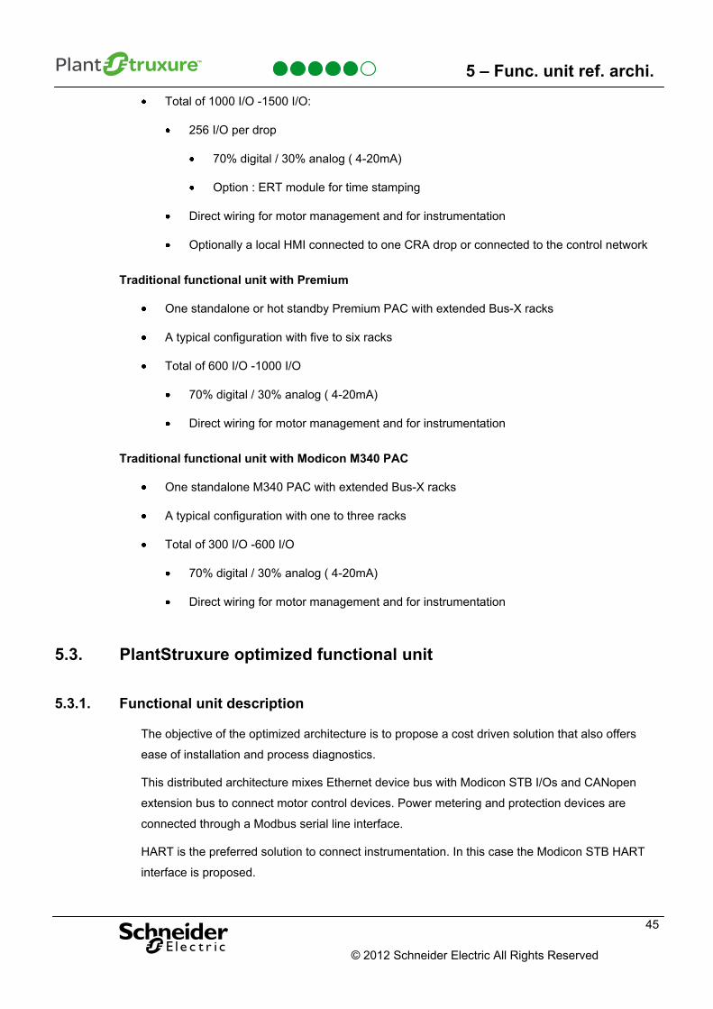
5.3. PlantStruxure optimized functional unit
5.3.1. Functional unit description
The objective of the optimized architecture is to propose a cost driven solution that also offers
ease of installation and process diagnostics.
This distributed architecture mixes Ethernet device bus with Modicon STB I/Os and CANopen
extension bus to connect motor control devices. Power metering and protection devices are
connected through a Modbus serial line interface.
HART is the preferred solution to connect instrumentation. In this case the Modicon STB HART
interface is proposed.
5 – Func. unit ref. archi.
© 2012 Schneider Electric All Rights Reserved
46
The three PAC platforms can be used in this class of architecture, even if M340 is the preferred
solution to deliver a cost driven architecture.
Figure 24: Optimized functional unit reference architecture
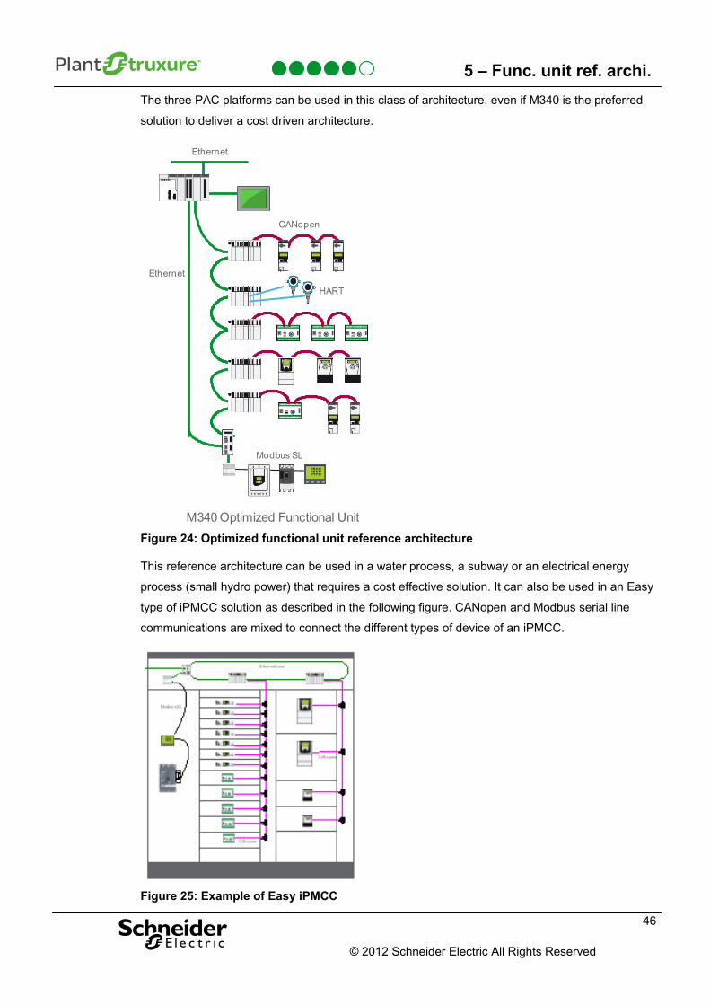
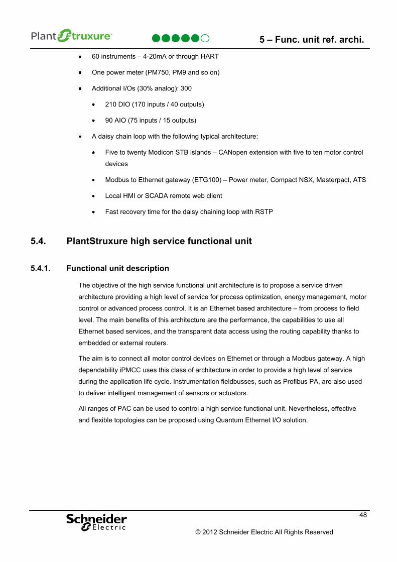
This reference architecture can be used in a water process, a subway or an electrical energy
process (small hydro power) that requires a cost effective solution. It can also be used in an Easy
type of iPMCC solution as described in the following figure. CANopen and Modbus serial line
communications are mixed to connect the different types of device of an iPMCC.
Figure 25: Example of Easy iPMCC
Ethernet
HART
Ethernet
Modbus SL
M340 Optimized Functional Unit
CANopen
5 – Func. unit ref. archi.
© 2012 Schneider Electric All Rights Reserved
47
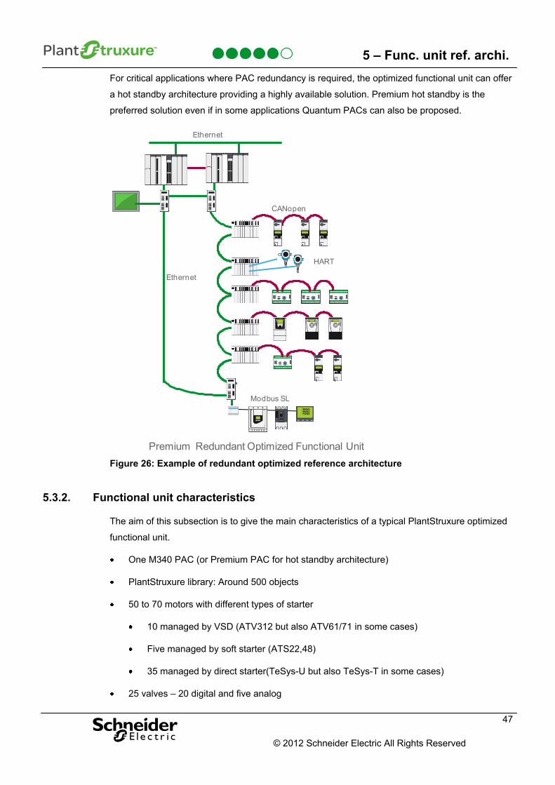
For critical applications where PAC redundancy is required, the optimized functional unit can offer
a hot standby architecture providing a highly available solution. Premium hot standby is the
preferred solution even if in some applications Quantum PACs can also be proposed.
Figure 26: Example of redundant optimized reference architecture
5.3.2. Functional unit characteristics
The aim of this subsection is to give the main characteristics of a typical PlantStruxure optimized
functional unit.
One M340 PAC (or Premium PAC for hot standby architecture)
PlantStruxure library: Around 500 objects
50 to 70 motors with different types of starter
10 managed by VSD (ATV312 but also ATV61/71 in some cases)
Five managed by soft starter (ATS22,48)
35 managed by direct starter(TeSys-U but also TeSys-T in some cases)
25 valves – 20 digital and five analog
Ethernet
HART
Ethernet
CANopen
Modbus SL
Premium Redundant Optimized Functional Unit
5 – Func. unit ref. archi.
© 2012 Schneider Electric All Rights Reserved
48
60 instruments – 4-20mA or through HART
One power meter (PM750, PM9 and so on)
Additional I/Os (30% analog): 300
210 DIO (170 inputs / 40 outputs)
90 AIO (75 inputs / 15 outputs)
A daisy chain loop with the following typical architecture:
Five to twenty Modicon STB islands – CANopen extension with five to ten motor control
devices
Modbus to Ethernet gateway (ETG100) – Power meter, Compact NSX, Masterpact, ATS
Local HMI or SCADA remote web client
Fast recovery time for the daisy chaining loop with RSTP
5.4. PlantStruxure high service functional unit
5.4.1. Functional unit description
The objective of the high service functional unit architecture is to propose a service driven
architecture providing a high level of service for process optimization, energy management, motor
control or advanced process control. It is an Ethernet based architecture – from process to field
level. The main benefits of this architecture are the performance, the capabilities to use all
Ethernet based services, and the transparent data access using the routing capability thanks to
embedded or external routers.
The aim is to connect all motor control devices on Ethernet or through a Modbus gateway. A high
dependability iPMCC uses this class of architecture in order to provide a high level of service
during the application life cycle. Instrumentation fieldbusses, such as Profibus PA, are also used
to deliver intelligent management of sensors or actuators.
All ranges of PAC can be used to control a high service functional unit. Nevertheless, effective
and flexible topologies can be proposed using Quantum Ethernet I/O solution.
5 – Func. unit ref. archi.
© 2012 Schneider Electric All Rights Reserved
49
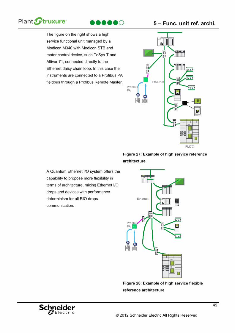
The figure on the right shows a high
service functional unit managed by a
Modicon M340 with Modicon STB and
motor control device, such TeSys-T and
Altivar 71, connected directly to the
Ethernet daisy chain loop. In this case the
instruments are connected to a Profibus PA
fieldbus through a Profibus Remote Master.
Figure 27: Example of high service reference
architecture
A Quantum Ethernet I/O system offers the
capability to propose more flexibility in
terms of architecture, mixing Ethernet I/O
drops and devices with performance
determinism for all RIO drops
communication.
Figure 28: Example of high service flexible
reference architecture
PAC
Ethernet
Profibus
PA
iPMCC
Ethernet
Profibus
PA
5 – Func. unit ref. archi.
© 2012 Schneider Electric All Rights Reserved
50
Modicon STB is recommended where there is small I/O density and no advanced functions are
required. Otherwise the remote I/O drops are preferred.
This functional unit reference architecture can be used in food and beverage, water, mining,
mineral and metal, electrical energy, or oil and gas applications that require a flexible solution
with high performance. This architecture can also be proposed for a high dependability iPMCC
solution.
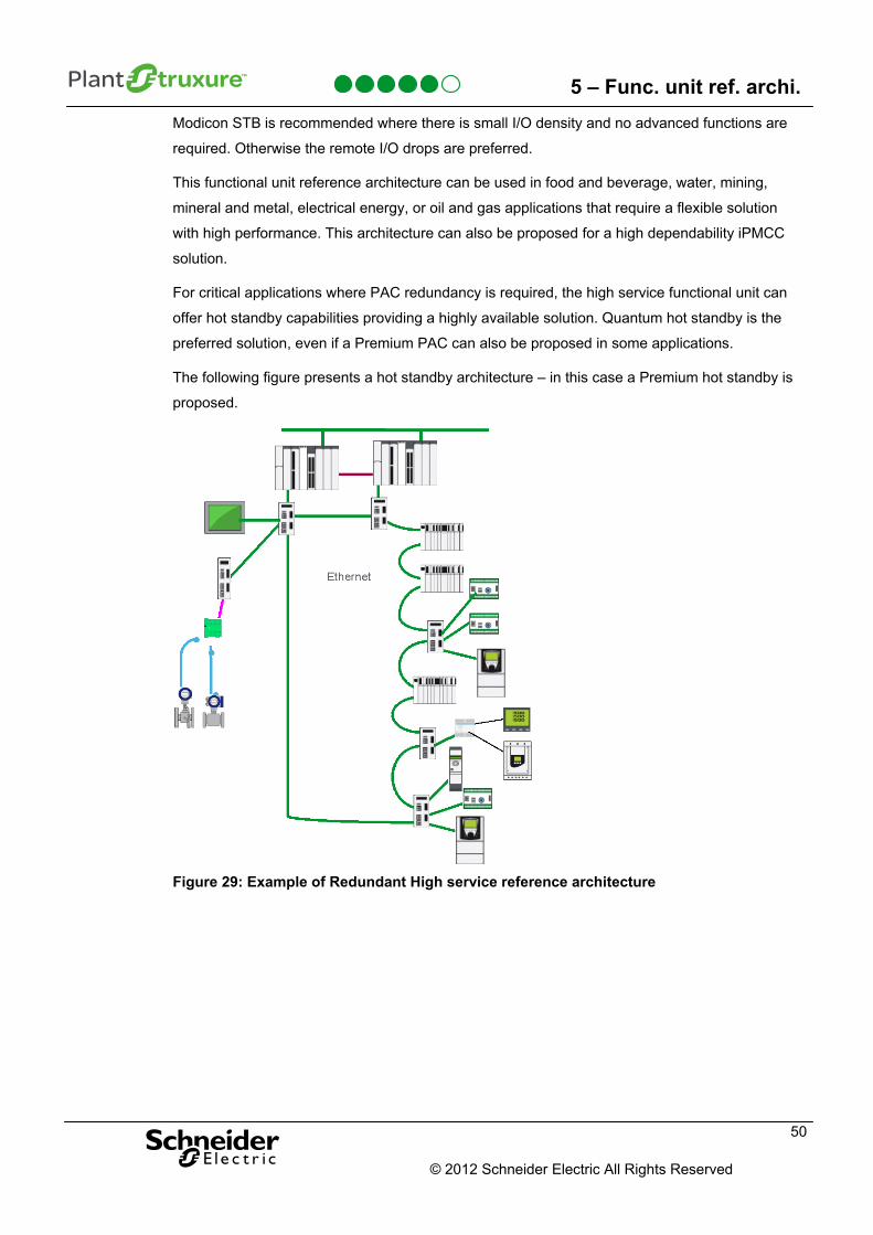
For critical applications where PAC redundancy is required, the high service functional unit can
offer hot standby capabilities providing a highly available solution. Quantum hot standby is the
preferred solution, even if a Premium PAC can also be proposed in some applications.
The following figure presents a hot standby architecture – in this case a Premium hot standby is
proposed.
Figure 29: Example of Redundant High service reference architecture
5 – Func. unit ref. archi.
© 2012 Schneider Electric All Rights Reserved
51
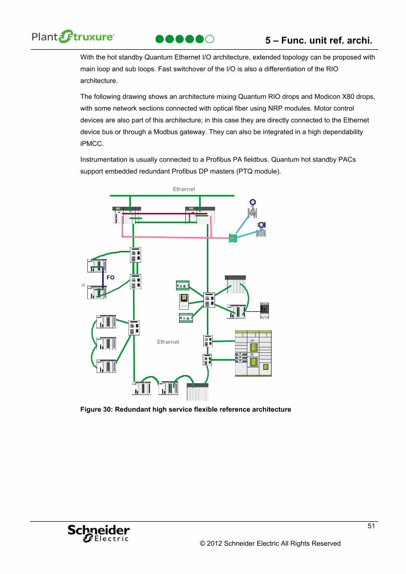
With the hot standby Quantum Ethernet I/O architecture, extended topology can be proposed with
main loop and sub loops. Fast switchover of the I/O is also a differentiation of the RIO
architecture.
The following drawing shows an architecture mixing Quantum RIO drops and Modicon X80 drops,
with some network sections connected with optical fiber using NRP modules. Motor control
devices are also part of this architecture; in this case they are directly connected to the Ethernet
device bus or through a Modbus gateway. They can also be integrated in a high dependability
iPMCC.
Instrumentation is usually connected to a Profibus PA fieldbus. Quantum hot standby PACs
support embedded redundant Profibus DP masters (PTQ module).
Figure 30: Redundant high service flexible reference architecture
FO
Ethernet
Ethernet
5 – Func. unit ref. archi.
© 2012 Schneider Electric All Rights Reserved
52
5.4.2. Functional unit characteristics
The aim of this subsection is to give the main characteristics of a typical PlantStruxure high
service functional unit.
High service
One Quantum PAC or one M340 (or Premium)
Standalone or hot standby architecture
PlantStruxure library: up to 1000 objects
Up to 100 motors with different types of starter
20 managed by VSD (ATV61,71)
10 managed by soft starter (ATS22,48)
70 managed by direct starter (TeSys-T)
40 valves – 30 digital and 10 analog
100 instruments – connected through Profibus PA or HART
An Ethernet daisy chain loop or star or mixed topology with:
TeSys-T and ATV 61/71
Power meter (PM800)
Modbus to Ethernet gateway to connect
Power meter (PM750, PM9)
Compact NSX, Masterpact
ATS 48, 22
Local HMI or SCADA remote web client
MV drive (optional)
Typically in one functional unit 5 to 10 Modicon STB
Profibus remote master to connect instrumentation
RSTP protocol to manage the loop
Routing capability from control to device level (Quantum 140 NOC 781 00)
Tofino Firewall
5 – Func. unit ref. archi.
© 2012 Schneider Electric All Rights Reserved
53
High service flexible
One Quantum PAC
Standalone or hot standby architecture
PlantStruxure library: 1000 objects and more
Up to 100 motors with different types of starter
20 managed by VSD (ATV71/61)
10 managed by soft starter (ATS22,48)
70 managed by direct starter (TeSys-T)
40 valves – 30 digital and 10 analog
100 instruments – connected through Profibus PA or HART
A loop with three or six RIO drops(Quantum and/or Modicon X80) – flexible architecture with
a main loop and four sub loops
A DRS or dual DRS to protect deterministic data flow
One or several DIO clouds for motor control devices – or integrated in an high dependability
iPMCC
Fiber optical link between RIO Modicon X80 drop if required
A Profibus remote master to connect instrumentation
Modbus serial line on a Modicon X80 drop
Routing capability from control to device level (Quantum 140 NOC 781 00)
Tofino Firewall

5 – Func. unit ref. archi.
© 2012 Schneider Electric All Rights Reserved
54
6 – Examples
© 2012 Schneider Electric All Rights Reserved
55
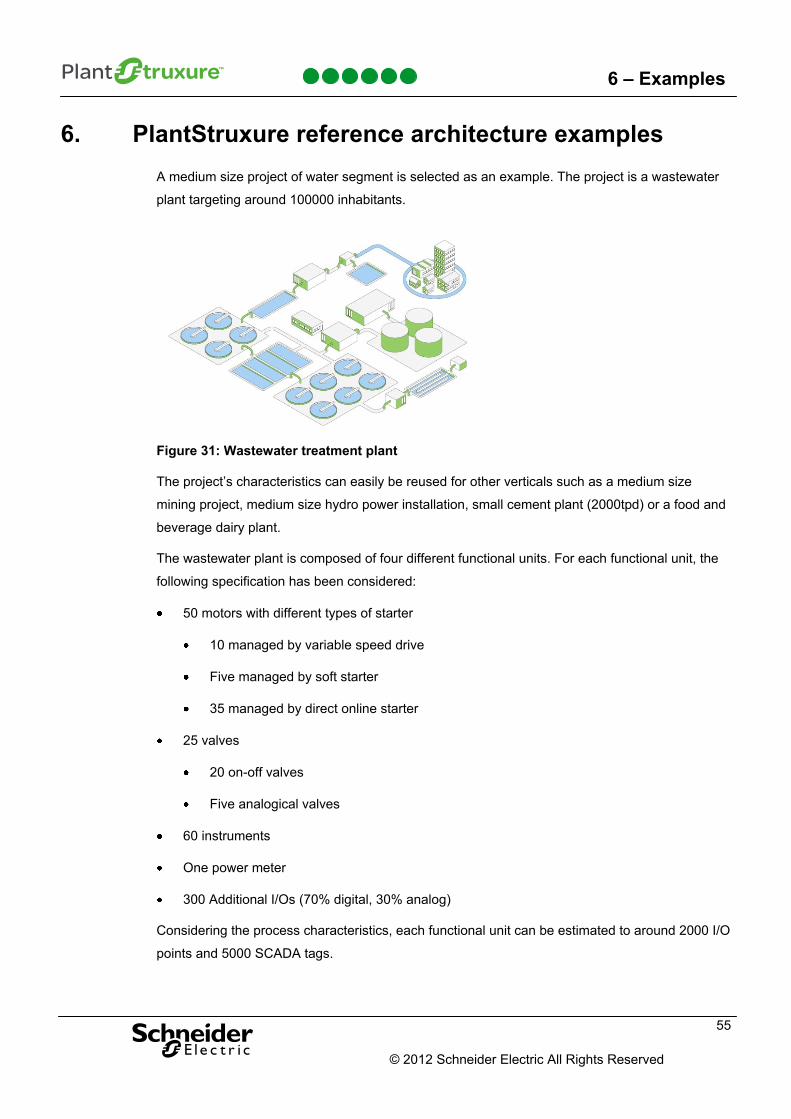
6. PlantStruxure reference architecture examples
A medium size project of water segment is selected as an example. The project is a wastewater
plant targeting around 100000 inhabitants.
Figure 31: Wastewater treatment plant
The project’s characteristics can easily be reused for other verticals such as a medium size
mining project, medium size hydro power installation, small cement plant (2000tpd) or a food and
beverage dairy plant.
The wastewater plant is composed of four different functional units. For each functional unit, the
following specification has been considered:
50 motors with different types of starter
10 managed by variable speed drive
Five managed by soft starter
35 managed by direct online starter
25 valves
20 on-off valves
Five analogical valves
60 instruments
One power meter
300 Additional I/Os (70% digital, 30% analog)
Considering the process characteristics, each functional unit can be estimated to around 2000 I/O
points and 5000 SCADA tags.
6 – Examples
© 2012 Schneider Electric All Rights Reserved
56
The main requirement is to have a cost oriented solution with good level of diagnostics,
maintenance and performance. In some part of the process, high availability is required.
Reporting is also strongly needed.
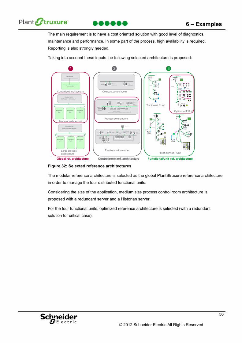
Taking into account these inputs the following selected architecture is proposed:
Figure 32: Selected reference architectures
The modular reference architecture is selected as the global PlantStruxure reference architecture
in order to manage the four distributed functional units.
Considering the size of the application, medium size process control room architecture is
proposed with a redundant server and a Historian server.
For the four functional units, optimized reference architecture is selected (with a redundant
solution for critical case).
Control room
Reference architecture
Functional
Unit
Functional
Unit
Functional
Unit
Control room
Reference architecture
Functional
Unit
Functional
Unit
Functional
Unit
1 2 3
Global ref. architecture Control room ref. architecture Functional Unit ref. architecture
Optimized F.Unit
Traditional F.Unit
High service F.Unit
Centralized architecture
Modular architecture
Large process
architecture
Compact control room
Process control room
Plant operation center
Control room
Functional Unit
Engineering StationServers
Operator Clients
Engineering Workstation
ServerOperator Workstation
Engineering StationServers
Operator Clients
Engineering Workstation
ServerOperator Workstation
Engineering Station/Asset management
SCADA ServersRedundant I/O server,alarm servertrends server
SCADA ServersRedundant I/O server,alarm servertrends server
Operators workstations
Historian Batchserver
Engineering Workstation/System servers
Assetmanagement
RedundantSCADAServers
BatchSystem
HistorianManufacturing
ExecutionSystem
ERP System
Global Operators workstations
Cluster 1 Cluster 2
Ethernet
Ethernet
HART
Ethernet
Modbus SL
PAC
Ethernet
Profibus
PA
6 – Examples
© 2012 Schneider Electric All Rights Reserved
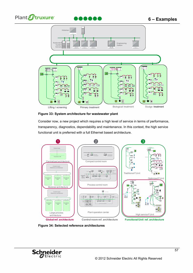
57
Figure 33: System architecture for wastewater plant
Consider now, a new project which requires a high level of service in terms of performance,
transparency, diagnostics, dependability and maintenance. In this context, the high service
functional unit is preferred with a full Ethernet based architecture.
Figure 34: Selected reference architectures
Engineering Station
RedundantSystemServers
Historian
Lifting / screening Primary treatment
Engineering Station
RedundantSystemServers
Historian
Lifting / screening Primary treatment Sludge treatmentBiological treatment treatment
Control room
Reference architecture
Functional
Unit
Functional
Unit
Functional
Unit
Control room
Reference architecture
Functional
Unit
Functional
Unit
Functional
Unit
1 2 3
Global ref. architecture Control room ref. architecture Functional Unit ref. architecture
Optimized F.Unit
Traditional F.Unit
High service F.Unit
Centralized architecture
Modular architecture
Large process
architecture
Compact control room
Process control room
Plant operation center
Control room
Functional Unit
Engineering StationServers
Operator Clients
Engineering Workstation
ServerOperator Workstation
Engineering StationServers
Operator Clients
Engineering Workstation
ServerOperator Workstation
Engineering Station/Asset management
SCADA ServersRedundant I/O server,alarm servertrends server
SCADA ServersRedundant I/O server,alarm servertrends server
Operators workstations
Historian Batchserver
Engineering Workstation/System servers
Assetmanagement
RedundantSCADAServers
BatchSystem
HistorianManufacturing
ExecutionSystem
ERP System
Global Operators workstations
Cluster 1 Cluster 2
Ethernet
Ethernet
HART
Ethernet
Modbus SL
PAC
Ethernet
Profibus
PA
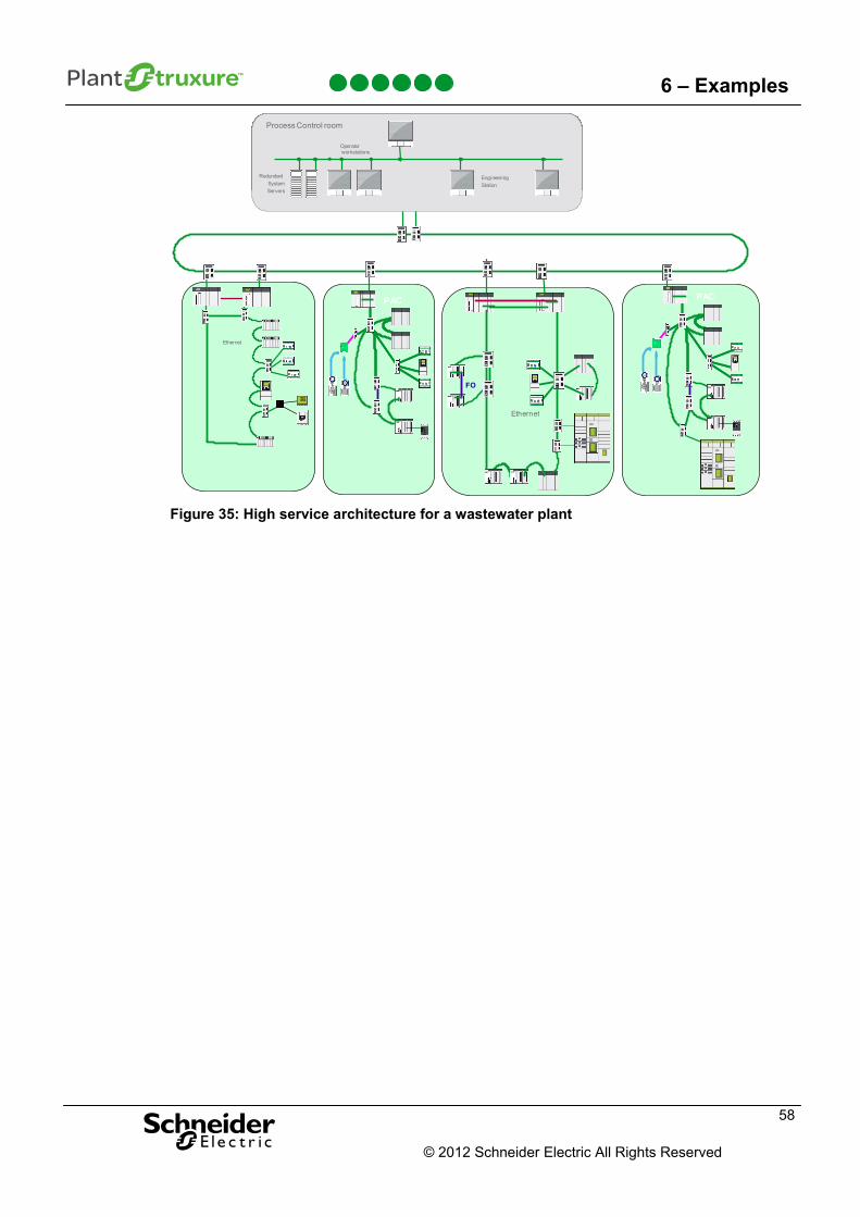
6 – Examples
© 2012 Schneider Electric All Rights Reserved
58
Figure 35: High service architecture for a wastewater plant
FO
Ethernet
PACPACPAC
Ethernet
PACPAC
Engineering
Station
Redundant
System
Servers
H is tor ian
Engineering
Station
Redundant
System
Servers
Process Control room
Operatorworkstations
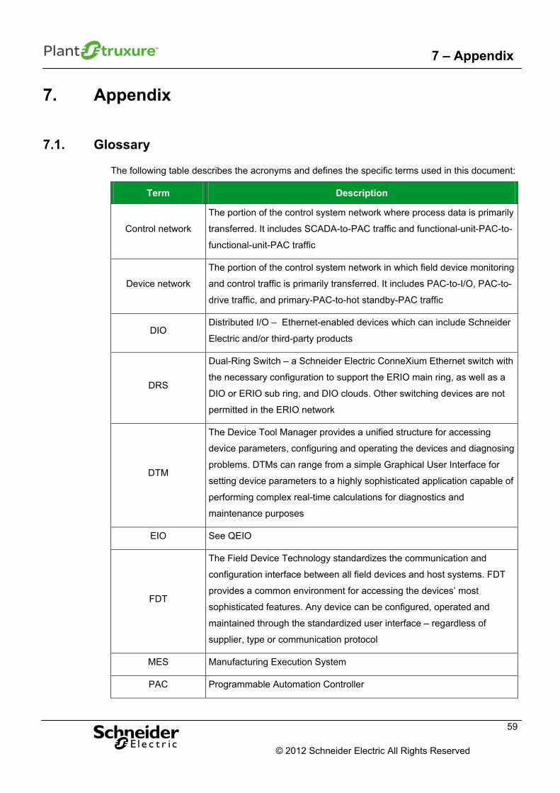
7 – Appendix
© 2012 Schneider Electric All Rights Reserved
59
7. Appendix
7.1. Glossary
The following table describes the acronyms and defines the specific terms used in this document:
Term Description
Control network
The portion of the control system network where process data is primarily
transferred. It includes SCADA-to-PAC traffic and functional-unit-PAC-to-
functional-unit-PAC traffic
Device network
The portion of the control system network in which field device monitoring
and control traffic is primarily transferred. It includes PAC-to-I/O, PAC-to-
drive traffic, and primary-PAC-to-hot standby-PAC traffic
DIO Distributed I/O – Ethernet-enabled devices which can include Schneider
Electric and/or third-party products
DRS
Dual-Ring Switch – a Schneider Electric ConneXium Ethernet switch with
the necessary configuration to support the ERIO main ring, as well as a
DIO or ERIO sub ring, and DIO clouds. Other switching devices are not
permitted in the ERIO network
DTM
The Device Tool Manager provides a unified structure for accessing
device parameters, configuring and operating the devices and diagnosing
problems. DTMs can range from a simple Graphical User Interface for
setting device parameters to a highly sophisticated application capable of
performing complex real-time calculations for diagnostics and
maintenance purposes
EIO See QEIO
FDT
The Field Device Technology standardizes the communication and
configuration interface between all field devices and host systems. FDT
provides a common environment for accessing the devices’ most
sophisticated features. Any device can be configured, operated and
maintained through the standardized user interface – regardless of
supplier, type or communication protocol
MES Manufacturing Execution System
PAC Programmable Automation Controller
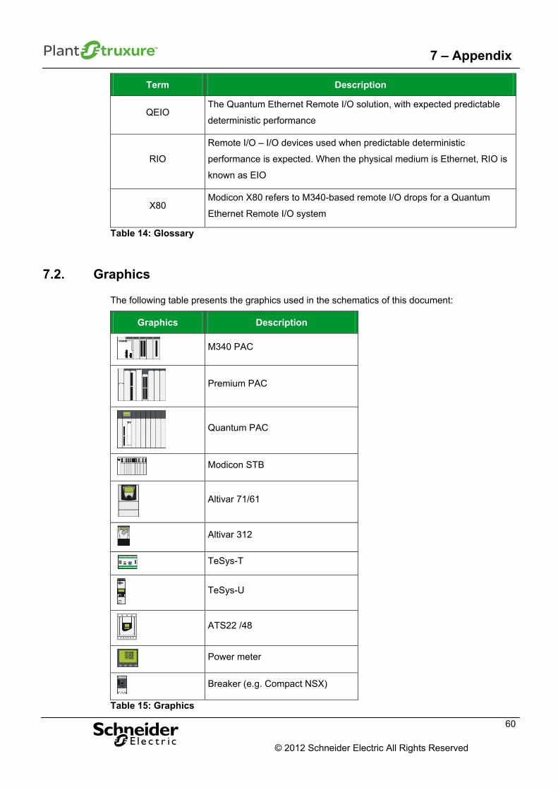
7 – Appendix
© 2012 Schneider Electric All Rights Reserved
60
Term Description
QEIO The Quantum Ethernet Remote I/O solution, with expected predictable
deterministic performance
RIO
Remote I/O – I/O devices used when predictable deterministic
performance is expected. When the physical medium is Ethernet, RIO is
known as EIO
X80 Modicon X80 refers to M340-based remote I/O drops for a Quantum
Ethernet Remote I/O system
Table 14: Glossary
7.2. Graphics
The following table presents the graphics used in the schematics of this document:
Graphics Description
M340 PAC
Premium PAC
Quantum PAC
Modicon STB
Altivar 71/61
Altivar 312
TeSys-T
TeSys-U
ATS22 /48
Power meter
Breaker (e.g. Compact NSX)
Table 15: Graphics
Altivar, ConneXium, Unity and Vijeo are trademarks or registered trademarks of Schneider Electric. Other
trademarks used herein are the property of their respective owners.
Schneider Electric Industries SAS
Head Office
35, rue Joseph Monier
92506 Rueil-Malmaison Cedex
FRANCE
www.schneider-electric.com
Due to evolution of standards and equipment, characteristics indicated in texts and images in this document are binding only after confirmation by our
departments.
Print:
Version 1.00 – 01 2013
Recommended