TE
CH
NI
CA
L
MA
NU
AL
Part No. PR06743000 Rev A 11/02
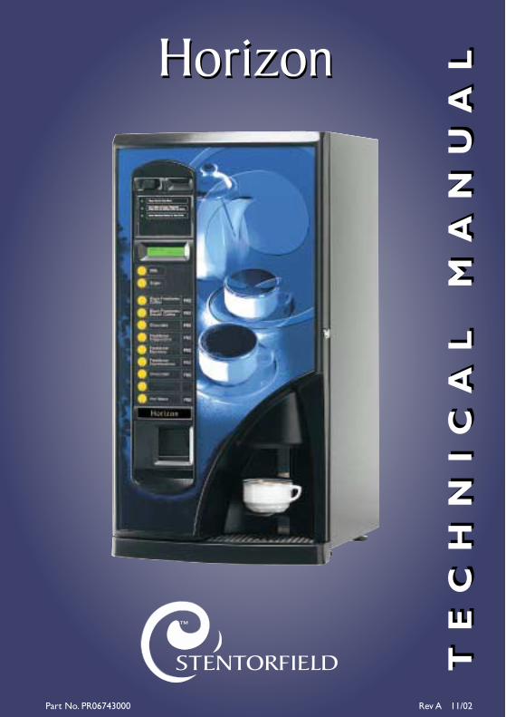
HorizonHorizon
TE
CH
NI
CA
L
MA
NU
AL

Contents
Page No.
Introduction ...................................................................................................2
Important Safeguards ...................................................................................2
Specification....................................................................................................3
Water Filter - Where Fitted.......................................................................3
External Features ..........................................................................................4
Internal Features ...........................................................................................5
Section 1 - Installation Procedure ............................................................6
Section 2 - Programming The Machine .................................................10
Section 3 - The Vend Cycle ......................................................................30
Section 4 - Technical Information ...........................................................38
Section 5 - Electrical/Electronic Information .......................................41
Section 6 - Figures and Diagrams...........................................................48
The following symbol is used throughout this Technical Manual:
Safety First! Take care, risk of personal injury.
© Copyright 2002 Crane Merchandising Systems
1
Technical Manual
Introduction
This manual is to be used by authorised personnel involved in installing, commissioningand servicing the Horizon table-top beverage system. The technical informationcontained within this document is for information only and may be changed withoutprior notice. Crane Merchandising Systems accepts no responsibility for any damagecaused to the machine through misinterpretation or misuse of the informationcontained in this document.
Upon receipt, carefully examine the machine checking for any damage ormissing/incorrect parts. Any discrepancy must be reported to Crane MerchandisingSystems in writing within three working days.
In accordance with the food hygiene regulations and in compliance with local PublicHealth Authorities, it is the responsibility of the operator to keep the machine in athoroughly clean condition.
Important Safeguards
When installing or servicing the Stentorfield Horizon, always have this manual availablefor quick and easy reference and always follow these basic safety precautions:
1. Ensure that the machine is situated on a strong horizontal surface, at a convenientheight and in a position where it is not likely to be knocked off.
2. The mains lead should never trail from the machine and should always be keptaway from hot surfaces and sharp edges.
3. Allow the machine to cool before handling or moving.
4. Ensure that the mains electricity supply is isolated before removing any of theprotective panels or undertaking any major servicing.Working on live equipmentshould only be undertaken when there is no practical alternative.
5. Never clean or service the brewer unit fitted to freshbrew machines whilst it isin motion as fingers may become trapped in the mechanism.
6. When servicing the heater tank be aware that water in the tank can reach atemperature of approximately 96° C.Water at this temperature can cause severeburns.
7. Never immerse the machine in water, or any other liquid.This machine must notbe installed in an area where a water jet may be used. Never use a water jet to
2
Technical Manual
clean this machine.
8. In normal operating conditions the machine should not freeze-up. In the unlikelyevent of the machine freezing, turn off the mains water supply, disconnect themachine from the mains electricity supply and contact Crane MerchandisingSystems for assistance.
9. Ensure that you are conversant with the ‘Health and Safety at Work and Electricityat Work Regulations 1989’.
This machine is for indoor use only and because it is a food machine, should be situatedin a clean, hygienic area.
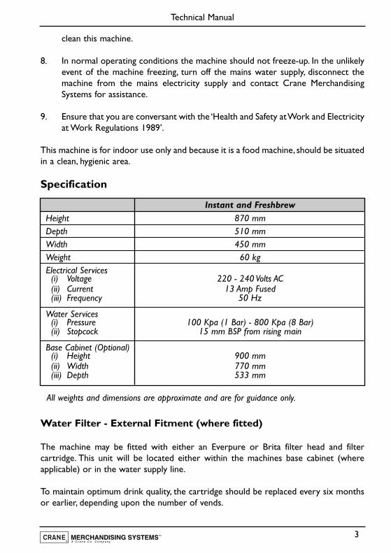
Specification
All weights and dimensions are approximate and are for guidance only.
Water Filter - External Fitment (where fitted)
The machine may be fitted with either an Everpure or Brita filter head and filtercartridge. This unit will be located either within the machines base cabinet (whereapplicable) or in the water supply line.
To maintain optimum drink quality, the cartridge should be replaced every six monthsor earlier, depending upon the number of vends.
3
Technical Manual
Instant and FreshbrewHeight 870 mmDepth 510 mmWidth 450 mmWeight 60 kgElectrical Services
(i) Voltage 220 - 240 Volts AC(ii) Current 13 Amp Fused(iii) Frequency 50 Hz
Water Services(i) Pressure 100 Kpa (1 Bar) - 800 Kpa (8 Bar)(ii) Stopcock 15 mm BSP from rising main
Base Cabinet (Optional)(i) Height 900 mm(ii) Width 770 mm(iii) Depth 533 mm
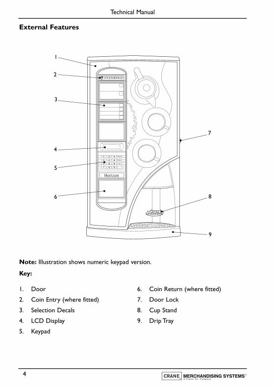
External Features
Note: Illustration shows numeric keypad version.
Key:
4
Technical Manual
Horizon
STENTORFIELD
1
2
3
4
6
5
7
8
9
1. Door
2. Coin Entry (where fitted)
3. Selection Decals
4. LCD Display
5. Keypad
6. Coin Return (where fitted)
7. Door Lock
8. Cup Stand
9. Drip Tray
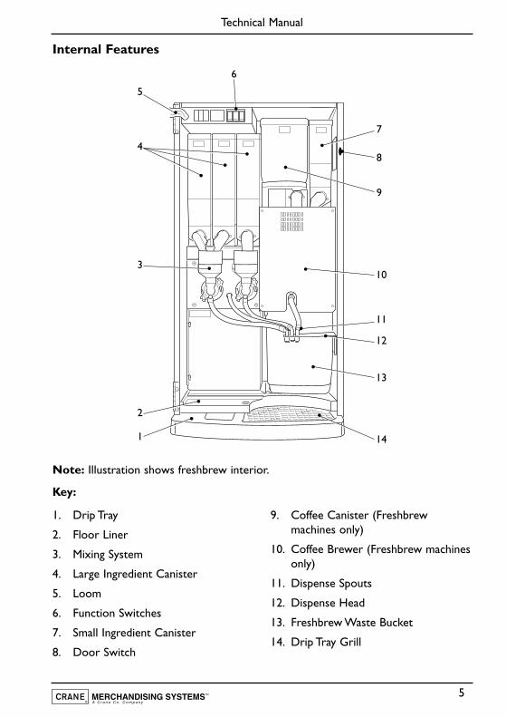
Internal Features
Note: Illustration shows freshbrew interior.
Key:
5
Technical Manual
6
7
9
8
10
11
12
13
141
2
3
4
5
1. Drip Tray
2. Floor Liner
3. Mixing System
4. Large Ingredient Canister
5. Loom
6. Function Switches
7. Small Ingredient Canister
8. Door Switch
9. Coffee Canister (Freshbrewmachines only)
10. Coffee Brewer (Freshbrew machinesonly)
11. Dispense Spouts
12. Dispense Head
13. Freshbrew Waste Bucket
14. Drip Tray Grill
Section 1 - Installation Procedure
Important!
It is essential that personnel responsible for installing, commissioning and servicing themachine understand the following:
1. The installation and commissioning of the machine should only be carried out bytrained and authorised service engineers.
2. All water and electrical services must be correctly and safely connected.
3. All covers should be replaced correctly and securely and the machine left in a safecondition.
1.1 Installing the Machine
1. The machine is suitable for indoor use only, sited in an area with a recommendedambient temperature not below 10º C and not exceeding 30º C.
2. Prior to moving the machine to its location, ensure that there is sufficient accessspace available via passageways, stairs, lifts, etc and that the table/counter wherethe machine is to be located is strong enough to safely support its weight. (Referto Specifications Table).
3. The machine should be located near the appropriate water and electrical servicesas detailed in the specification table.
4. To ensure adequate ventilation, 100 - 150 mm (4 - 6 inches) clearance must beallowed between the back of the cabinet and the wall.
5. Unlock and open the cabinet door. Remove all transit packing and the installationkit from the machine. Check for visual signs of damage which may have occurredduring transit.
6. If the machine is damaged or any parts are missing, you must contact the supplierimmediately.
7. The machine should be levelled in both front to back and side to side planes usingthe four adjustable levelling feet (12 mm thread).Check for correct alignment usinga spirit level placed on the floor of the machine.
6
Technical Manual
Note! Incorrect levelling can result in:
(a) Door misalignment.
(b) Coin acceptance reduction.
1.2 Connecting the Water Supply
1. The machine should be situated within 1 metre of a drinking water supply froma rising main, terminating with a W.R.C. approved 15mm compression stop tap.
2. The water supply should comply with both the Statutory Instrument No.1147 -“Water, England and Wales” and The Water Supply (Water Quality) Regulations1989.Water pressure at the stop tap must be within the limits 1 - 8 Bar (100 Kpa -800 Kpa).
3. Connect the flexi-hose supplied with the machine to the stop tap ensuring that theseal supplied is fitted correctly.Flush the system via the stop tap (several gallons) beforeconnecting the hose to the machine.
4. Connect the hose to the inlet valve located on the rear of the machine. Ensure thatthe seal is correctly fitted. Ensure that all water supply fittings are tight.Turn on thestop tap and check for leaks.
1.3 Connecting the Electricity Supply
Safety First! THE MACHINE MUST BE EARTHED. ON NO ACCOUNTSHOULD IT BE EARTHED TO THE WATER SUPPLY PIPE
1. The machine must be connected to a 240 Volt 50Hz 13 amp fused switched socketoutlet, installed to the latest edition of the IEE regulations, using a 3 pin BSapproved 13 amp fused plug.
2. Machines are despached from the factory with the input transformer connectedfor a 240 volt supply. If the electrical supply differs, the alternative tapping (230volt or 220 volt) should be used.
Important: If the mains lead becomes damaged in any way it must be replaced by aspecial lead available from the manufacturer.
7
Technical Manual
1.4 Commissioning Procedure
The following procedure must be carried out by a trained installation engineer beforethe machine can be used for the first time.
1. Ensure that the electrical and water services to the machine are connectedcorrectly and turned on. Ensure that the waste tray is fitted correctly to themachine.
2. Open the front door of the machine. Insert the safety key supplied with themachine into the door switch.The machine is now on.
3. Whilst the boiler in the machine is filling, the display will show the message:
4. As the water in the boiler starts to heat, the message on the LCD will change to:
5. Ensure that no water overflows from the boiler tank overflow pipe into the wastetray. Check the system for leaks.
Safety First! Should the machine fail to fill correctly or leak, turn off thestopcock and contact the machine supplier for assistance.
6. Check the LCD display on the front of the machine to ensure that the water hasheated to the correct temperature and that the machine is in standby mode.Thedisplay will show the message:
Where XX:XX is the current time.
7. Remove the ingredient canisters - DO NOT place ingredient canisters on thefloor.
Remove the lids from the ingredient canisters. Fill the canisters with the correctingredients, re-fit the lids and re-fit canisters into machine.
8. Referring to Section 2 of this manual,“Programming The Machine”, use the menu
8
Technical Manual
SORRY NOT IN USELOW WATER
SORRY NOT IN USEWATER HEATING
PLEASE SELECT DRINKTIME XX:XX
selections available in the operator’s and engineer’s programs to program therequired settings for correct machine operation.
9. Press the test vend switch, located in the switch panel mounted above theingredient canisters, to check that the machine operates correctly. Place an emptycup under the dispense head before vending the selection.
10. If the machine is fitted with a coin/card mecahanism, check that the mechanismand cash box operate correctly.
11. Remove the safety key. Fit the door switch bracket to the door using the twoscrews provided. Ensure that the bracket will operate the door switch when thedoor is closed. Check for leaks and ensure that the machine is left in a clean andsafe condition.
9
Technical Manual
Section 2 - Programming The Machine
2.1 Modes Of Operation
The machine has three operating modes:
1. Standby Mode - The machine is ready to dispense a vend and displays the timeand type of credit input required.This is followed by the vend cycle and a returnto the standby mode.
2. Operator’s Program - Accessed by pressing the program switch and thenentering the operator’s code via the keypad.This enables the operator to accesssub-programs in order to change information relating to time, drink, price periodsetc. It is not possible to vend a drink from within the operator’s program.
3. Engineer’s Program - Accessed by pressing the program switch and thenentering the engineer’s code via the keypad. The engineer may then access anumber of sub-programs in order to alter the ingredient dispense and machineparameters or use the machine test facilities.
2.2 Programming Mode
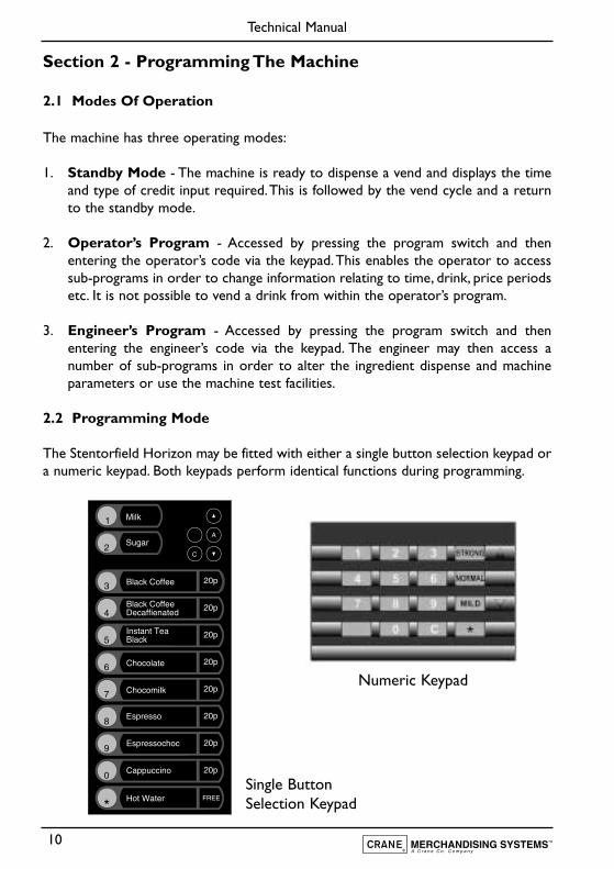
The Stentorfield Horizon may be fitted with either a single button selection keypad ora numeric keypad. Both keypads perform identical functions during programming.
10
Technical Manual
Numeric Keypad
Single ButtonSelection Keypad
11
Technical Manual
To access the programming mode you need to enter a sequence of key strokes on thekeypad.The time between each key stroke must be less than 5 seconds otherwise themachine will return to standby mode. Once in programming mode there is no timeconstraint.
During programming the buttons/keys are used as follows:
0 - 9 Used for data entry
“C” Used for correcting data and entering a higher program level
Blank For moving to a higher program level
▲ For indexing up in a program
Normal For entering data in a program, or entering a lower program level
▼ For indexing down in a program
Note: To avoid confusion, in this manual the Normal key will be referred to as theAccess key.
2.3 Accessing the Programming Mode
In order to enter the Engineer's or Operator's programs proceed as follows:-
1. Press the program entry switch,mounted in the panel located above the ingredientcanisters, followed by the appropriate access code. Code entry errors may beerased using the cancel (C) key.
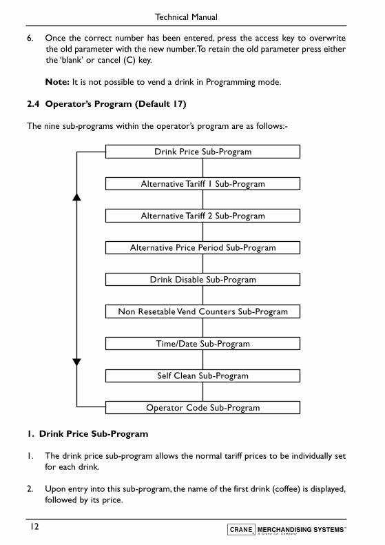
2. With the correct code entered the title of the first sub-program will be displayedon the LCD. In the engineers program the LCD will display the message:
3. To step through the sub programs, press either the up (▲) or down (▼) keys.
4. To access a displayed sub program, press the access (normal) key.
5. If any numerical data parameter is entered, it may be changed in one of two ways:
(a) Pressing the up (▲) or down (▼) keys increases or decreases the number oneach key press.
(b) Keying in the actual digits of the number required. Using this method, the newnumber will be displayed in place of the current parameter.
KEYPAD TESTSUB PROGRAM
12
Technical Manual
6. Once the correct number has been entered, press the access key to overwritethe old parameter with the new number.To retain the old parameter press eitherthe ‘blank’ or cancel (C) key.
Note: It is not possible to vend a drink in Programming mode.
2.4 Operator’s Program (Default 17)
The nine sub-programs within the operator’s program are as follows:-
1. Drink Price Sub-Program
1. The drink price sub-program allows the normal tariff prices to be individually setfor each drink.
2. Upon entry into this sub-program, the name of the first drink (coffee) is displayed,followed by its price.
Drink Price Sub-Program
Alternative Tariff 1 Sub-Program
Alternative Tariff 2 Sub-Program
Alternative Price Period Sub-Program
Drink Disable Sub-Program
Non Resetable Vend Counters Sub-Program
Time/Date Sub-Program
Self Clean Sub-Program
Operator Code Sub-Program
13
Technical Manual
The LCD will display the following message:
N.B. Freshbrew machines will display coffee whereas instant machines will show tea.
3. To alter the drink price, press the access key.The LCD will display the followingmessage:
4. The = symbol changes to a > symbol indicating that it is now possible for newdata to be entered. Key in the new price using the keypad and when correct pressaccess to overwrite the old data.
5. The prices for other drinks can now be set following the sequence described in2.2 - Programming Mode.
2. Alternative Tariff 1 Sub-Program
This sub-program works in exactly the same way as the drink price sub program andhas the same appearance. The prices set in this program will be in force during tariff1 periods.
3. Alternative Tariff 2 Sub-Program
This is identical to the alternative tariff 1 sub-program except that the prices set herewill be in force during tariff 2 periods.
4. Alternative Price Period Sub-Program
This sub-program enables the times to be specified when each of the above tariffsshould be in force.There is a four level tariff structure available:
1. Normal Tariff:Prices set in the drink price sub-program and in force when no alternativeprice period is currently applicable.
2. Tariff 1:Prices set in the tariff 1 price sub-program.
3. Tariff 2:Prices set in the tariff 2 price sub-program.
4. Tariff 0:Sets the machine into free vend.
COFFEEPRICE = 10
COFFEEPRICE > 10
14
Technical Manual
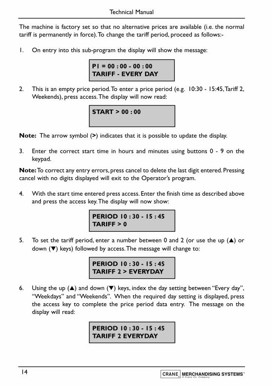
The machine is factory set so that no alternative prices are available (i.e. the normaltariff is permanently in force).To change the tariff period, proceed as follows:-
1. On entry into this sub-program the display will show the message:
2. This is an empty price period.To enter a price period (e.g. 10:30 - 15:45,Tariff 2,Weekends), press access.The display will now read:
Note: The arrow symbol (>) indicates that it is possible to update the display.
3. Enter the correct start time in hours and minutes using buttons 0 - 9 on thekeypad.
Note:To correct any entry errors, press cancel to delete the last digit entered. Pressingcancel with no digits displayed will exit to the Operator’s program.
4. With the start time entered press access. Enter the finish time as described aboveand press the access key.The display will now show:
5. To set the tariff period, enter a number between 0 and 2 (or use the up (▲) ordown (▼) keys) followed by access.The message will change to:
6. Using the up (▲) and down (▼) keys, index the day setting between “Every day”,“Weekdays” and “Weekends”. When the required day setting is displayed, pressthe access key to complete the price period data entry. The message on thedisplay will read:
START > 00 : 00
PERIOD 10 : 30 - 15 : 45TARIFF > 0
PERIOD 10 : 30 - 15 : 45TARIFF 2 > EVERYDAY
PERIOD 10 : 30 - 15 : 45TARIFF 2 EVERYDAY
P1 = 00 : 00 - 00 : 00TARIFF - EVERY DAY
7. There are a maximum of ten possible price periods available. To enter anotherprice period, use the up (▲) or down (▼) keys to view the periods until an emptyperiod is displayed. The new period is entered in the same way as describedpreviously.
8. If the start time is entered as being a later time than the finish time, the periodwill not be accepted by the machine. If periods overlap, the first overlapping periodin the list will be the one in force until it has finished. To delete a period, continueas if that period were to be re-programmed, and when the display is requestingthe start time to be entered, press cancel.
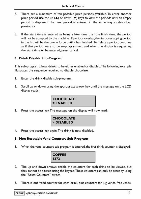
5. Drink Disable Sub-Program
This sub-program allows drinks to be either enabled or disabled.The following exampleillustrates the sequence required to disable chocolate.
1. Enter the drink disable sub-program.
2. Scroll up or down using the appropriate arrow key until the message on the LCDdisplay reads:
3. Press the access key.The message on the display will now read:
4. Press the access key again.The drink is now disabled.
6. Non Resetable Vend Counters Sub-Program
1. When the vend counters sub-program is entered, the first drink counter is displayed:
2. The up and down arrows enable the counters for each drink to be viewed, butthey cannot be altered using the keypad.These counters can only be reset by usingthe “Reset Counters” switch.
3. There is one vend counter for each drink, plus counters for jug vends, free vends,
15
Technical Manual
CHOCOLATE> DISABLED
COFFEE1372
CHOCOLATE= ENABLED
total vends and total sales value.The total sales data is displayed in units of 1 penny.
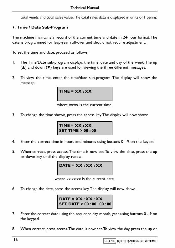
7. Time / Date Sub-Program
The machine maintains a record of the current time and date in 24-hour format.Thedate is programmed for leap-year roll-over and should not require adjustment.
To set the time and date, proceed as follows:
1. The Time/Date sub-program displays the time, date and day of the week.The up(▲) and down (▼) keys are used for viewing the three different messages.
2. To view the time, enter the time/date sub-program. The display will show themessage:
where xx:xx is the current time.
3. To change the time shown, press the access key.The display will now show:
4. Enter the correct time in hours and minutes using buttons 0 - 9 on the keypad.
5. When correct, press access.The time is now set.To view the date, press the upor down key until the display reads:
where xx:xx:xx is the current date.
6. To change the date, press the access key.The display will now show:
7. Enter the correct date using the sequence day, month, year using buttons 0 - 9 onthe keypad.
8. When correct, press access.The date is now set.To view the day, press the up or
16
Technical Manual
TIME = XX : XX
DATE = XX : XX : XX
DATE = XX : XX : XXSET DATE > 00 : 00 : 00 : 00
TIME = XX : XXSET TIME > 00 : 00
down key until the display reads:
where xxxxxxxxx is the current day of the week.
9. To change the day, press the access key.The display will now show:
10. Use the up or down arrow keys until the required day is displayed. Press the accesskey. The time, date and day are now programmed.
8. Self Clean Sub-Program
The auto flush feature on the machine enables the operator to define two daily timesat which the machine will flush through the water system.
1. The auto flush sequence is similar to the flush sequence initiated by the flushswitch. The “Sorry Not In Use: Self Cleaning” message is displayed, the blockerenabled and the controller waits until the water is at the correct temperature setby the thermostat. In order to guarantee the highest standards of cleanliness, theboiler fill valve is disabled, ensuring that the water used in the self-cleaning cycleis kept at the optimum temperature to kill any germs which may have accumulated.
2. Each hot water valve is switched on in sequence for the specified flush time, (setin the miscellaneous settings program). While the valves are on, they are ‘rattled’(to remove any limescale which may have accumulated on them) and theircorresponding whippers are run.
3. Once the auto flush cycle is completed, the controller refills the boiler to thecorrect level. When the correct water temperature is obtained, the machinereturns to standby mode.
5. Auto flush periods can be selected to occur everyday, weekdays, weekends ornever.
6. To enter auto flush times, follow the sequence described for setting an "alternativeprice period"
17
Technical Manual
DAY = XXXXXXXXX
DAY = XXXXXXXXX> XXXXXXXXX
9. Operator Code Sub-Program (Default 17)
Entry into the “operator code sub-program” enables the operator code to be changed.This code may be of any length up to seven digits. Enter a new code at the promptand when correct press access.
10. Reset Counters Switch
1. This switch, operated from within the operator’s program, enables the operatorto reset the vend counters to zero. When the “Reset Counters” function isactivated, the machine will give an intermittent bleep and flash the followingmessage on the display:
2. The operator must press the cancel key to clear the display and return to theoperator’s program. This ensures that if the “Reset Counters” is inadvertentlyactivated, the operator is aware that the counters have been reset.
18
Technical Manual
COUNTERS RESET
19
Technical Manual
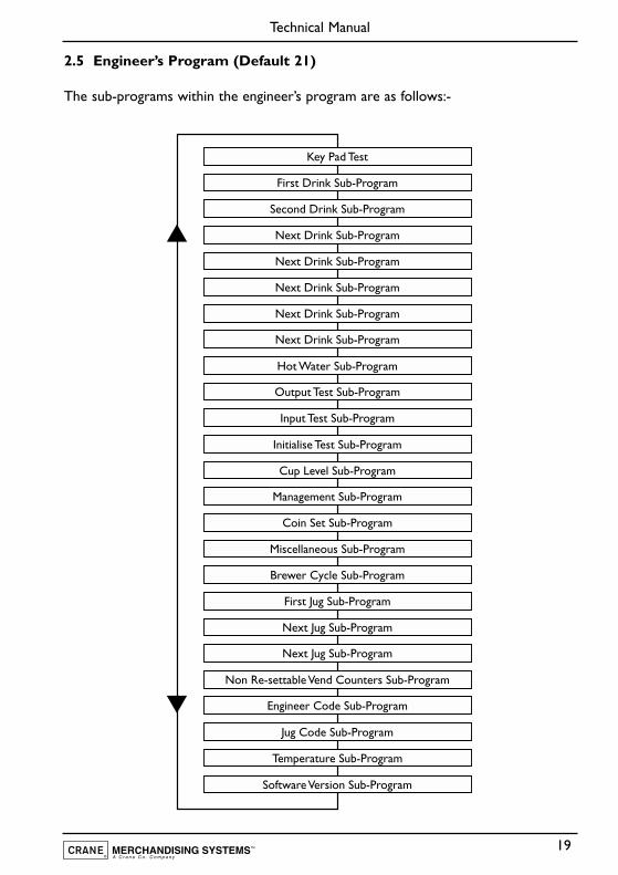
2.5 Engineer’s Program (Default 21)
The sub-programs within the engineer’s program are as follows:-
Key Pad Test
First Drink Sub-Program
Second Drink Sub-Program
Next Drink Sub-Program
Next Drink Sub-Program
Next Drink Sub-Program
Next Drink Sub-Program
Next Drink Sub-Program
Hot Water Sub-Program
Output Test Sub-Program
Input Test Sub-Program
Initialise Test Sub-Program
Cup Level Sub-Program
Management Sub-Program
Coin Set Sub-Program
Miscellaneous Sub-Program
Brewer Cycle Sub-Program
First Jug Sub-Program
Next Jug Sub-Program
Next Jug Sub-Program
Non Re-settable Vend Counters Sub-Program
Engineer Code Sub-Program
Jug Code Sub-Program
Temperature Sub-Program
Software Version Sub-Program
20
Technical Manual
1. Keypad Test Sub-Program
The keypad test sub-program enables the engineer to test each key on the keypad toensure that it is operating correctly.
1. Whenever a key is pressed, the name of that key will be displayed on the LCD.Because the access key was pressed to enter the sub-program, on entry to thissub-program the LCD will display:
2. For numerical keys, the number will be displayed, such as ‘1’ key or ‘2’ key. Forother keys, the name of the key will be displayed, such as strong or mild.
3. To exit from this sub-program into the engineer program, press the blank key.
2. Drink Ingredient Sub-Program
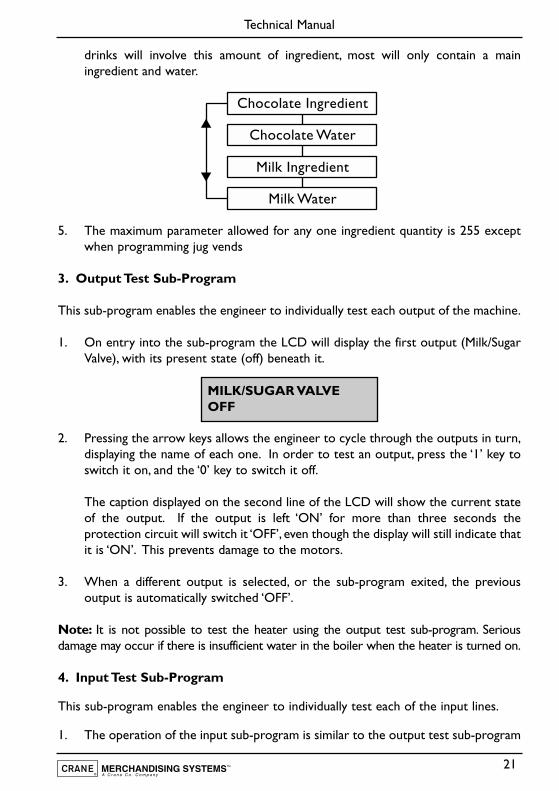
The drink ingredient sub-programs allow the ingredient quantities for each drink to beadjusted to accommodate different ingredient types and taste requirements. Proceedas follows:
1. On entry into the ingredient sub-programs, the first ingredient to be displayed isthe ingredient which constitutes the major part of the drink. In the case of tea,this will be:
2. All ingredient quantities are displayed in twentieth of a second increments.Therefore a quantity of 40 actually means that the ingredient is dispensed for fortytwentieths, or two seconds thus simplifying the calculation of ingredient quantities.The engineer does not need to consider the exact weight or volume of ingredientand has an immediate idea of the approximate time taken to dispense a sensiblequantity.
3. The quantity may be altered in the same way as other parameters areprogrammed. Depending on the drink type, there may be a number of differentingredient values to be adjusted. For each ingredient value there is an associatedwater value, again measured in twentieths of a second.
4. The diagram (page 21) illustrates the ingredients that may be involved in the make-up of a drink.The chocomilk sub-program (Instant) is used as an example. Not all
ACCESS KEY
TEAINGREDIENT = 40
21
Technical Manual
drinks will involve this amount of ingredient, most will only contain a mainingredient and water.
5. The maximum parameter allowed for any one ingredient quantity is 255 exceptwhen programming jug vends
3. Output Test Sub-Program
This sub-program enables the engineer to individually test each output of the machine.
1. On entry into the sub-program the LCD will display the first output (Milk/SugarValve), with its present state (off) beneath it.
2. Pressing the arrow keys allows the engineer to cycle through the outputs in turn,displaying the name of each one. In order to test an output, press the ‘1’ key toswitch it on, and the ‘0’ key to switch it off.
The caption displayed on the second line of the LCD will show the current stateof the output. If the output is left ‘ON’ for more than three seconds theprotection circuit will switch it ‘OFF’, even though the display will still indicate thatit is ‘ON’. This prevents damage to the motors.
3. When a different output is selected, or the sub-program exited, the previousoutput is automatically switched ‘OFF’.
Note: It is not possible to test the heater using the output test sub-program. Seriousdamage may occur if there is insufficient water in the boiler when the heater is turned on.
4. Input Test Sub-Program
This sub-program enables the engineer to individually test each of the input lines.
1. The operation of the input sub-program is similar to the output test sub-program
Chocolate Water
Chocolate Ingredient
Milk Water
Milk Ingredient
MILK/SUGAR VALVEOFF
22
Technical Manual
except that the display shows the name of the input and the caption indicates its’current state:
2. As the state of the input changes, so does the caption on the second line of theLCD. There is a delay of approximately three-quarters of a second before thedisplay caption changes to ensure that any rapid changes can be seen.
5. Initialise Sub-Program
The initialise sub-program enables the engineer to return all the parameters to theirfactory settings.
1. Upon entry into the initialise sub-program, the display will show the message:
2. To initialise the machine, press access twice. The display will now show:
3. The LCD will flash this message accompanied by an intermittent beep.To returnto the engineer’s program or standby mode, it is necessary to press the cancelbutton. This ensures that should the initialise sub-program ever be inadvertentlyactivated, the engineer cannot overlook the fact that the machine has beeninitialised.
6. Cup Level Sub-Program
1. The cup level sub-program allows the amount of water used in each cup vend tobe altered on a percentage basis. This enables different size cups to be usedwithout having to change each drink ingredient quantity. Jug vends remainunaffected.
2. The sub-program will display the percentage cup level which may be altered in thesame way as all other parameters. 100% cup level will dispense the exact amountof water set in the drink ingredient sub-programs. A percentage below 100 willdispense less water, and a percentage above 100 will dispense more.
COIN INPUT 1pOFF
USE ACCESS KEY FOR INITIALISATION
INITIALISED
23
Technical Manual
7. Management Sub-Program
The management sub-program informs the controller which hardware aspects of themachine have been selected.
The “Coin System” program displays the type of coin system selected. To change theselection, press the access key followed by the up (▲) or down (▼) keys to display therequired selection. Enter the new selection by pressing the access key. If the machineis not fitted with a coin system, the option “Free Vend Only” should be selected.
8. Coin Set Sub-Program
The coin set sub-program enables the coin set to be changed to suit the coin mechanismfitted to the machine. The coin set used by the coin mechanism is totally transparent to thecontroller ensuring that the displayed message in the standby mode correctly indicates whichcoins may be entered.
The possible coin sets are:
1p - 20p 5c - 20c1p - 50p 5c - 50c
1p - 100p 5c - 1
5p - 50p 5c - 25p - 100p5p - 200p
These are selected in the same way as parameters in the “management sub-program”.
Note: This sub-program is not accessible if “Free Vend Only” or “Card System” isselected in the management sub-program.
9. Miscellaneous Settings Sub-Program
The miscellaneous settings sub-program allows various delays and timings to be setwhich will affect all of the drinks in the machine. These settings may be viewed andchanged in the same manner as the parameters in the “ingredient sub-programs”.
1. Water Start To Ingredient Start DelayThe water start to ingredient start delay defines the time between water startingto be dispensed and the ingredient starting to be dispensed. If ingredient reachesthe mixing bowl before the water, it may stick to the sides of the bowl.This delayensures that ingredient is always dispensed into a bowl already containing water.
2. Water Stop To Whipper Stop DelayThe water stop to whipper stop delay defines the length of time that the whipper
24
Technical Manual
will continue to run after the water valve has closed.This ensures that the whipperoperates whenever there is water in the mixing bowl.
3. Strong Increase - Numerical Keypad Models OnlyThis defines the amount of extra ingredient to be dispensed for a “strong” drinkand is added to the amount of ingredient set in the ingredient quantity sub-programs.
4. Mild Decrease - Numerical Keypad Models OnlyThe mild decrease defines the amount of ingredient to be subtracted from theamount set in the ingredient quantity sub-programs when a “mild” drink isrequested.
5. Water Flush TimeThis setting is the period of time that a valve is opened during a flush cycle. It isgenerally set slightly higher than the period set for a vend to ensure that the mixingbowl is filled further than during a vend. Care should be taken to ensure that theperiod set does not cause the bowl to overflow.
6. Freshbrew/Instant ConfigurationThis sub-program enables the machine to be set up for either Freshbrew (brewerfitted) or Instant operation. Select the option required and then initialise themachine.
7. Cappuccino Chocolate ConfigurationThe cappuccino chocolate option enables the machine to be configured todispense cappuccino drinks with or without chocolate topping. For a traditionalstyle cappuccino drink, disable the chocolate option and fill the milk canister withcappuccino topping.
10. Brewer Cycle Sub-Program - Instant Models Only
The brewer cycle sub-program allows the engineer to adjust the four brewer delayperiods in order to obtain the optimum drink strength.The timings for each delay arethe same as those described for the “drink ingredient sub-program”.
11. Jug Ingredient Sub-Programs - Instant Models Only
The jug ingredient sub-programs determine the ingredients for jug vends. Because jugvends are always black with no sugar, the only quantities which need to be entered areingredient and water.The maximum quantity allowed for each is 1499.
25
Technical Manual
12. Non-Resettable Vend Counters Sub-Program
1. When the vend counters sub-program is entered, the first drink counter isdisplayed:
2. Pressing the up (▲) or down (▼) arrow keys enables the counters for each drinkto be viewed, but they do not allow the counters to be altered.
3. There is one vend counter for each drink, plus counters for each jug vend, totalvends and total sales vends. Additionally, an “Engineer Entry” counter isincremented each time the engineer’s program is accessed.These counters cannotbe reset and will remain intact for the service life of the controller board.
13. Engineer Code Entry Sub-Program (Default 21 - Over-ride 1121678)
Entry into the engineer code entry sub-program allows the engineer code to bechanged.This code may be of any length up to seven digits. Enter a new code at theprompt and when correct, press access.
Note: If a zero code is entered, the machine will remain in the engineer’s programcontinually, so the zero code will have to be withdrawn. A code of zero is also enteredif the engineer attempts to alter the code and then exits the sub-program withoutentering any number.
14. Jug Code Sub-Program - Numeric Keypad Models Only
1. The jug code is a two digit security code that when entered correctly via thekeypad, followed by a two digit drink selection number, allows a jug to be vended.Entry into the jug code sub program allows the engineer to set a unique jug code.
2. Access the jug code sub-program and enter a new code using buttons 0-9 on thekeypad. Press access to overwrite the old code.
15. Temperature Sub-Program
The temperature sub-program allows the parameters controlling boiler temperatureand temperature display to be altered. There are four parameters which may be altered.
1. Maximum Temperature
This is the maximum temperature to which the water will be heated andmaintained at and must be set to a value greater than the minimum temperature.
TEA1372
2. Minimum Temperature
This is the minimum water temperature at which a drink may be dispensed. If anattempt is made to vend a drink with the temperature below this value whenminimum temperature is enabled, the following message will be displayed:
3. Minimum Temperature Enable / Disable
This feature allows the engineer to enable or disable the vending of drinks belowthe minimum temperature.
4. Temperature Display
Allows the actual temperature to be displayed (free vend only).
16. Software Version Sub-Program
The software version sub-program displays the serial number of the software versionrunning on the machine and is for information only.
2.6 Vend Counters
1. The vend counters record the number of drinks/jug vends dispensed and theprices charged for them. Each drink type has a separate counter with an additionalcounter for each jug vend. A “Total Vend” counter keeps a record of the numberof vends dispensed and is incremented each time a drink is dispensed.
2. The counters are accessible from within both the operator's and engineer'sprograms. From the operator's program they may be reset using the “ResetCounters” function or the “Engineer’s Initialise Sub-Program”. When accessedfrom within the engineer’s program, the counters are non resettable.This ensuresthat a cumulative record is kept throughout the service life of the controller board.
3. Each time the engineer’s program is entered, an “Engineer Entry” counter isincremented.This acts as a security feature, ensuring that the engineer’s code maynot be used without leaving evidence that the program has been entered.
2.7 Pre-Set Values
The tables on the following pages illustrate the pre-set values for all of the parameterswhich may be changed in the operator’s or engineer’s programs.These are the valueswith which the machine leaves the factory. If the “Initialise” sub-program is activated,each one of these values will be restored into the memory of the controller.
26
Technical Manual
SORRY NOT IN USEWATER HEATING
27
Technical Manual
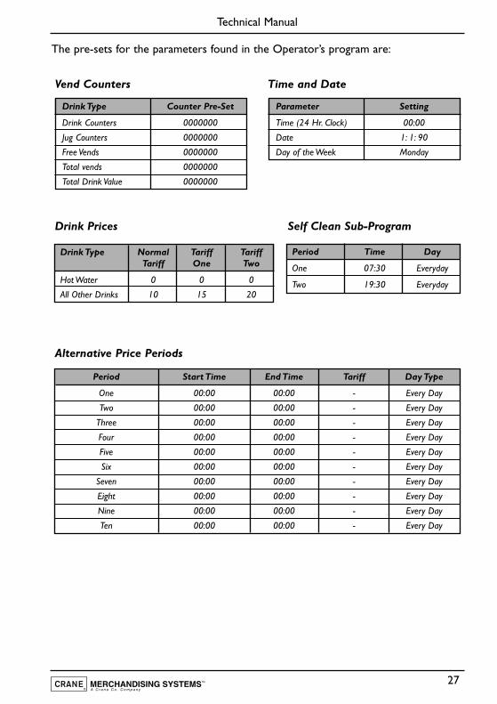
The pre-sets for the parameters found in the Operator’s program are:
Vend Counters Time and Date
Drink Prices Self Clean Sub-Program
Alternative Price Periods
Drink Type Counter Pre-Set
Drink Counters 0000000
Jug Counters 0000000
Free Vends 0000000
Total vends 0000000
Total Drink Value 0000000
Parameter Setting
Time (24 Hr. Clock) 00:00
Date 1: 1: 90
Day of the Week Monday
Drink Type Normal Tariff TariffTariff One Two
Hot Water 0 0 0
All Other Drinks 10 15 20
Period Time Day
One 07:30 Everyday
Two 19:30 Everyday
Period Start Time End Time Tariff Day Type
One 00:00 00:00 - Every Day
Two 00:00 00:00 - Every Day
Three 00:00 00:00 - Every Day
Four 00:00 00:00 - Every Day
Five 00:00 00:00 - Every Day
Six 00:00 00:00 - Every Day
Seven 00:00 00:00 - Every Day
Eight 00:00 00:00 - Every Day
Nine 00:00 00:00 - Every Day
Ten 00:00 00:00 - Every Day
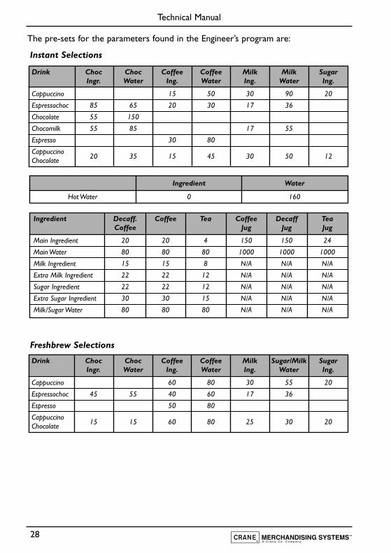
The pre-sets for the parameters found in the Engineer’s program are:
Instant Selections
Freshbrew Selections
28
Technical Manual
Drink Choc Choc Coffee Coffee Milk Milk SugarIngr. Water Ing. Water Ing. Water Ing.
Cappuccino 15 50 30 90 20
Espressochoc 85 65 20 30 17 36
Chocolate 55 150
Chocomilk 55 85 17 55
Espresso 30 80
Cappuccino20 35 15 45 30 50 12Chocolate
Ingredient Water
Hot Water 0 160
Ingredient Decaff. Coffee Tea Coffee Decaff TeaCoffee Jug Jug Jug
Main Ingredient 20 20 4 150 150 24
Main Water 80 80 80 1000 1000 1000
Milk Ingredient 15 15 8 N/A N/A N/A
Extra Milk Ingredient 22 22 12 N/A N/A N/A
Sugar Ingredient 22 22 12 N/A N/A N/A
Extra Sugar Ingredient 30 30 15 N/A N/A N/A
Milk/Sugar Water 80 80 80 N/A N/A N/A
Drink Choc Choc Coffee Coffee Milk Sugar/Milk SugarIngr. Water Ing. Water Ing. Water Ing.
Cappuccino 60 80 30 55 20
Espressochoc 45 55 40 60 17 36
Espresso 50 80
Cappuccino15 15 60 80 25 30 20Chocolate
29
Technical Manual
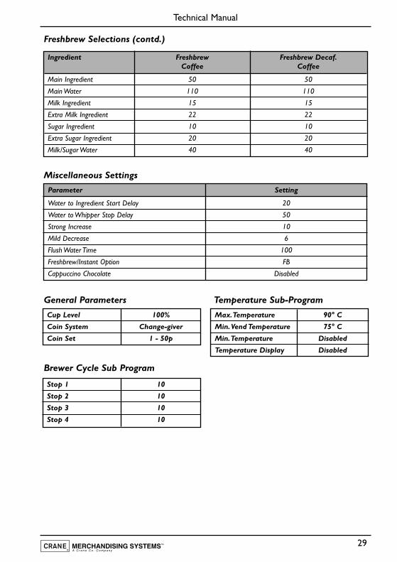
Freshbrew Selections (contd.)
Miscellaneous Settings
General Parameters Temperature Sub-Program
Brewer Cycle Sub Program
Ingredient Freshbrew Freshbrew Decaf.Coffee Coffee
Main Ingredient 50 50
Main Water 110 110
Milk Ingredient 15 15
Extra Milk Ingredient 22 22
Sugar Ingredient 10 10
Extra Sugar Ingredient 20 20
Milk/Sugar Water 40 40
Parameter Setting
Water to Ingredient Start Delay 20
Water to Whipper Stop Delay 50
Strong Increase 10
Mild Decrease 6
Flush Water Time 100
Freshbrew/Instant Option FB
Cappuccino Chocolate Disabled
Cup Level 100%
Coin System Change-giver
Coin Set 1 - 50p
Stop 1 10
Stop 2 10
Stop 3 10
Stop 4 10
Max.Temperature 90° C
Min.Vend Temperature 75° C
Min.Temperature Disabled
Temperature Display Disabled
30
Technical Manual
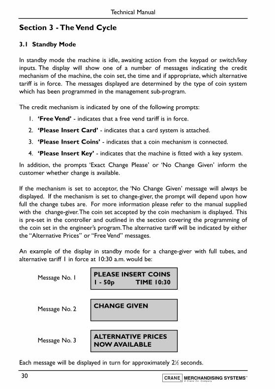
Section 3 - The Vend Cycle
3.1 Standby Mode
In standby mode the machine is idle, awaiting action from the keypad or switch/keyinputs. The display will show one of a number of messages indicating the creditmechanism of the machine, the coin set, the time and if appropriate, which alternativetariff is in force. The messages displayed are determined by the type of coin systemwhich has been programmed in the management sub-program.
The credit mechanism is indicated by one of the following prompts:
1. ‘Free Vend’ - indicates that a free vend tariff is in force.
2. ‘Please Insert Card’ - indicates that a card system is attached.
3. ‘Please Insert Coins’ - indicates that a coin mechanism is connected.
4. ‘Please Insert Key’ - indicates that the machine is fitted with a key system.
In addition, the prompts ‘Exact Change Please’ or ‘No Change Given’ inform thecustomer whether change is available.
If the mechanism is set to acceptor, the ‘No Change Given’ message will always bedisplayed. If the mechanism is set to change-giver, the prompt will depend upon howfull the change tubes are. For more information please refer to the manual suppliedwith the change-giver.The coin set accepted by the coin mechanism is displayed. Thisis pre-set in the controller and outlined in the section covering the programming ofthe coin set in the engineer’s program.The alternative tariff will be indicated by eitherthe “Alternative Prices” or “Free Vend” messages.
An example of the display in standby mode for a change-giver with full tubes, andalternative tariff 1 in force at 10:30 a.m. would be:
Message No. 1
Message No. 2
Message No. 3
Each message will be displayed in turn for approximately 21⁄2 seconds.
PLEASE INSERT COINS1 - 50p TIME 10:30
CHANGE GIVEN
ALTERNATIVE PRICESNOW AVAILABLE
31
Technical Manual
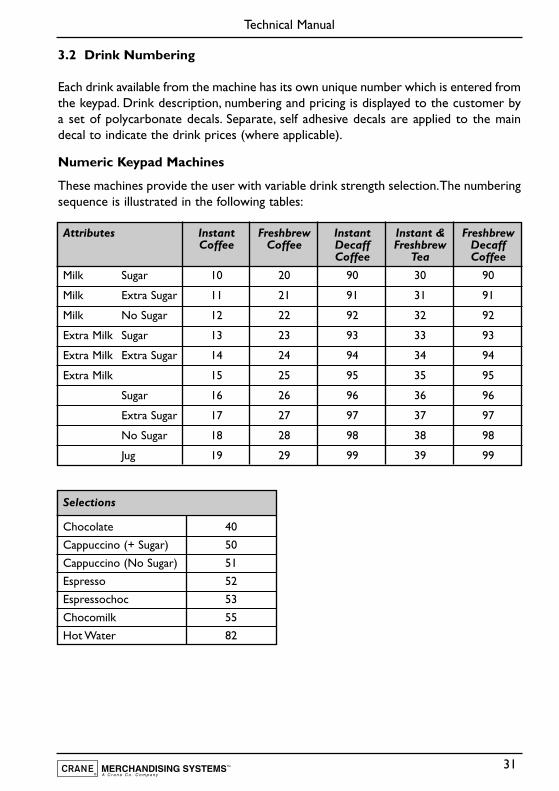
3.2 Drink Numbering
Each drink available from the machine has its own unique number which is entered fromthe keypad. Drink description, numbering and pricing is displayed to the customer bya set of polycarbonate decals. Separate, self adhesive decals are applied to the maindecal to indicate the drink prices (where applicable).
Numeric Keypad Machines
These machines provide the user with variable drink strength selection.The numberingsequence is illustrated in the following tables:
Attributes Instant Freshbrew Instant Instant & FreshbrewCoffee Coffee Decaff Freshbrew Decaff
Coffee Tea Coffee
Milk Sugar 10 20 90 30 90
Milk Extra Sugar 11 21 91 31 91
Milk No Sugar 12 22 92 32 92
Extra Milk Sugar 13 23 93 33 93
Extra Milk Extra Sugar 14 24 94 34 94
Extra Milk 15 25 95 35 95
Sugar 16 26 96 36 96
Extra Sugar 17 27 97 37 97
No Sugar 18 28 98 38 98
Jug 19 29 99 39 99
Selections
Chocolate 40
Cappuccino (+ Sugar) 50
Cappuccino (No Sugar) 51
Espresso 52
Espressochoc 53
Chocomilk 55
Hot Water 82
32
Technical Manual
3.3 Replacing/Updating Drink Selection Decals
To update drink pricing or replace drink description decals, proceed as follows:
1. Ensure that the machine is switched off and disconnected from the mainselectricity supply. Open the cabinet door.
2. Remove the four screws securing the panel located on the rear of the door.Carefully remove the panel.
Numeric Keypad Machines
1. Locate the decal holder containing the decal to be updated. Carefully push thedecal holder out of the door complete with the decal.
2. Remove the decal from the holder and update as required. Refit the decal holderensuring that it is positioned correctly.
3. Repeat steps 1 and 2 for any other decals that need updating.
4. Refit panel securely to the rear of the door. Close the cabinet door and switchon the power to the machine.
Single Button Selection Machines
1. Unscrew and remove the two knurled plastic nuts securing the selectionmembrane.
2. Moving to the front of the door, carefully ease the membrane away from the door.Remove relevant decals from their slide in pockets and update as appropriate.
3. Refit the selection membrane to the door and secure with the two knurled plasticnuts.
4. Refit panel securely to the rear of the door. Close the cabinet door and switchon the power to the machine.
3.4 Drink Selection
Numeric Keypad Machines
Drink selections are made by entering the two digit number for the drink required asshown in the previous tables. Any numerical entry errors may be corrected using the“C” key.This will cancel the last digit displayed on the LCD. In this section, we shall
33
Technical Manual
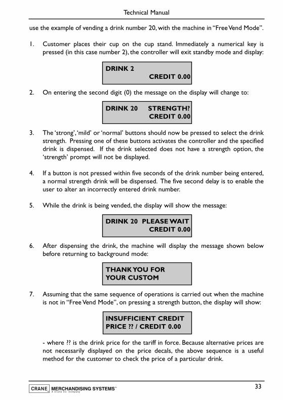
use the example of vending a drink number 20, with the machine in “Free Vend Mode”.
1. Customer places their cup on the cup stand. Immediately a numerical key ispressed (in this case number 2), the controller will exit standby mode and display:
2. On entering the second digit (0) the message on the display will change to:
3. The ‘strong’, ‘mild’ or ‘normal’ buttons should now be pressed to select the drinkstrength. Pressing one of these buttons activates the controller and the specifieddrink is dispensed. If the drink selected does not have a strength option, the‘strength’ prompt will not be displayed.
4. If a button is not pressed within five seconds of the drink number being entered,a normal strength drink will be dispensed. The five second delay is to enable theuser to alter an incorrectly entered drink number.
5. While the drink is being vended, the display will show the message:
6. After dispensing the drink, the machine will display the message shown belowbefore returning to background mode:
7. Assuming that the same sequence of operations is carried out when the machineis not in “Free Vend Mode”, on pressing a strength button, the display will show:
- where ?? is the drink price for the tariff in force. Because alternative prices arenot necessarily displayed on the price decals, the above sequence is a usefulmethod for the customer to check the price of a particular drink.
DRINK 2CREDIT 0.00
DRINK 20 STRENGTH?CREDIT 0.00
DRINK 20 PLEASE WAITCREDIT 0.00
THANK YOU FORYOUR CUSTOM
INSUFFICIENT CREDITPRICE ?? / CREDIT 0.00
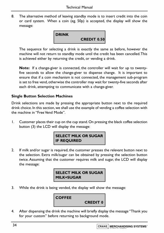
8. The alternative method of leaving standby mode is to insert credit into the coinor card system. When a coin (eg. 50p) is accepted, the display will show themessage:
The sequence for selecting a drink is exactly the same as before, however themachine will not return to standby mode until the credit has been cancelled.Thisis achieved either by returning the credit, or vending a drink.
Note: If a change-giver is connected, the controller will wait for up to twenty-five seconds to allow the change-giver to dispense change. It is important toensure that if a coin mechanism is not connected, the management sub-programis set to free vend,otherwise the controller may wait for twenty-five seconds aftereach drink, attempting to communicate with a change-giver.
Single Button Selection Machines
Drink selections are made by pressing the appropriate button next to the requireddrink choice. In this section, we shall use the example of vending a coffee selection withthe machine in “Free Vend Mode”.
1. Customer places their cup on the cup stand.On pressing the black coffee selectionbutton (3) the LCD will display the message:
2. If milk and/or sugar is required, the customer presses the relevant button next tothe selection. Extra milk/sugar can be obtained by pressing the selection buttontwice. Assuming that the customer requires milk and sugar, the LCD will displaythe message:
3. While the drink is being vended, the display will show the message:
4. After dispensing the drink the machine will briefly display the message “Thank youfor your custom” before returning to background mode.
34
Technical Manual
DRINKCREDIT 0.50
COFFEECREDIT 0
SELECT MILK OR SUGARIF REQUIRED
SELECT MILK OR SUGARMILK+SUGAR
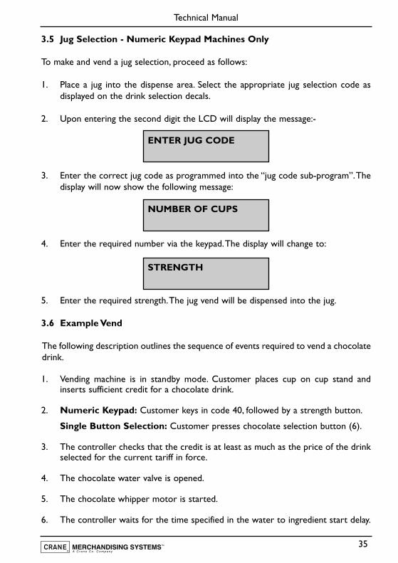
3.5 Jug Selection - Numeric Keypad Machines Only
To make and vend a jug selection, proceed as follows:
1. Place a jug into the dispense area. Select the appropriate jug selection code asdisplayed on the drink selection decals.
2. Upon entering the second digit the LCD will display the message:-
3. Enter the correct jug code as programmed into the “jug code sub-program”.Thedisplay will now show the following message:
4. Enter the required number via the keypad.The display will change to:
5. Enter the required strength.The jug vend will be dispensed into the jug.
3.6 Example Vend
The following description outlines the sequence of events required to vend a chocolatedrink.
1. Vending machine is in standby mode. Customer places cup on cup stand andinserts sufficient credit for a chocolate drink.
2. Numeric Keypad: Customer keys in code 40, followed by a strength button.
Single Button Selection: Customer presses chocolate selection button (6).
3. The controller checks that the credit is at least as much as the price of the drinkselected for the current tariff in force.
4. The chocolate water valve is opened.
5. The chocolate whipper motor is started.
6. The controller waits for the time specified in the water to ingredient start delay.
35
Technical Manual
ENTER JUG CODE
NUMBER OF CUPS
STRENGTH
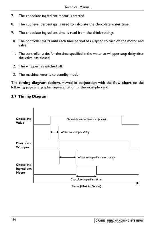
7. The chocolate ingredient motor is started.
8. The cup level percentage is used to calculate the chocolate water time.
9. The chocolate ingredient time is read from the drink settings.
10. The controller waits until each time period has elapsed to turn off the motor andvalve.
11. The controller waits for the time specified in the water to whipper stop delay afterthe valve has closed.
12. The whipper is switched off.
13. The machine returns to standby mode.
The timing diagram (below), viewed in conjunction with the flow chart on thefollowing page is a graphic representation of the example vend.
3.7 Timing Diagram
36
Technical Manual
Water to ingredient start delay
Chocolate ingredient time
Water to whipper delay
Chocolate water time x cup level
Time (Not to Scale)
ChocolateValve
ChocolateWhipper
ChocolateIngredientMotor
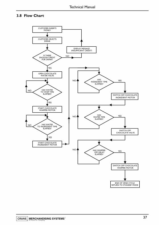
3.8 Flow Chart
37
Technical Manual
IS THEREENOUGH CREDIT
FOR DRINK?
HASINGREDIENT TIME
ELAPSED?
HASWATER TIME
ELAPSED?
HAS WHIPPER OFF DELAY
ELAPSED?
HAS WATERTO WHIP TIME
ELAPSED?
HAS WATERTO INGREDIENT TIME
ELAPSED?
CUSTOMER INSERTSMONEY
CUSTOMER SELECTSDRINK
DISPLAY MESSAGEìINSUFFICIENT CREDITî
OPEN CHOCOLATEWATER VALVE
START CHOCOLATEWHIPPER MOTOR
SWITCH OFF CHOCOLATE INGREDIENT MOTOR
SWITCH OFF CHOCOLATE VALVE
SWITCH OFF CHOCOLATE WHIPPER MOTOR
END OF VEND CYCLERETURN TO STANDBY MODE
START CHOCOLATEINGREDIENT MOTOR
NO
NO
NO
YES
YES
YES
YES
NO
NO
NO
YES
YES
Section 4 - Technical Information
4.1 Water Services
The mains water supply provides water for the boiler.Water enters at the rear of themachine through a solenoid operated inlet valve which opens or closes the watersupply as required.
4.2 Hot Water System
1. Water is heated in the boiler to the required temperature by a heating elementrated at 2.4 Kilowatts.
2. The mains voltage required for the element is switched by a solid state relay,controlled by the vending machine controller via an analogue signal transmittedby the thermistor probe.
3. The water level inside the boiler is controlled by a water level probe.When thewater drops below the required level, the controller board operates the mainswater inlet valve until the required water level is restored.
4. A series of control valves are mounted on the outside of the boiler.These supplyheated water to the mixing stations where ingredients are added to make thedrink.
4.3 Water Supply
1. Should the inlet valve fail (or mains water supply be disabled), the controller boardwill detect a fault after the inlet valve “open” signal has been active for 2 minutesor the required water level has not been reached.
2. At this point the keypad will be disabled, all outputs from the controller board(including the heater element) will be switched off and the display will show themessage:
4.4 Ingredient Dispense
1. The ingredients required for making up a drink are contained in ingredientcanisters and are dispensed by means of a motor driven auger located in the baseof each canister.
38
Technical Manual
SORRY NOT IN USELOW WATER
2. The amount of product dispensed by each canister is controlled by the vendingmachine controller and may be adjusted via timing constants set in the engineersprogram - refer to Section 2 of this manual, Programming The Machine, for furtherdetails.
3. The required ingredients for each vend are delivered to a mixing bowl, where theyare blended with hot water by a high speed whipper prior to discharge at thedispense head.
4. To ensure a free flow of ingredient powder and granules, it is essential that theyare kept completely dry. This is achieved by extracting steam from the mixingsystem using an extract fan.
Note! The fan runs continuously whilst the cabinet door switch is in the on position.
5. The electrical supply for the extract fan is 110 Volts AC.
4.5 Brewer Unit - (Freshbrew Models)
1. The brewer unit provides a freshly brewed coffee vend.The coffee ingredient isdispensed into the brewer unit via the canister.
2. A 110 Volt motor, controlled by an index cam fitted to the drive shaft, operatesthe brewer unit. The cam operates a switch which sends a logic signal to thecontroller when the brewer is in the correct position.
4.6 Coin and Card/Key Systems
The Stentorfield Horizon may be equipped with coin or card/key validation systemsusing Mars protocol ‘A’. The coin or card/key system informs the vending machinecontroller of the amount of credit which has been deposited into the vending machine.
4.7 Change Giver
1. The Change Giver communicates with the vending machine controller through aserial communication interface. It will validate a coin and if accepted, send a signalto the vending machine controller indicating the total amount of money which hasbeen tendered since the last vend.
2. Once sufficient credit has been accumulated a vend will be permitted.The vendingmachine controller will communicate to the change giver the actual price of thedrink dispensed. The change giver will return any change due to the customer,provided the change tubes contain coinage above a pre-set level.
39
Technical Manual
4.8 Coin Blocker
For Horizon machines fitted with a change-giver, a logic “low” level from the vendingmachine controller will disable any coin acceptance.
4.9 Card/Key System
1. The card system fitted to the machine communicates with the vending machinecontroller using the same principle as the change giver.
2. The card system informs the vending machine controller of the amount of crediton the customer's card. If there is sufficient credit for the selected drink, thevending machine controller permits a vend and informs the card system of theamount of credit to be taken from the card. The new balance will then be re-written onto the customer's card.
Note! For full information and programming instructions for all of these systems,please refer to the user manual supplied with the validation system.
40
Technical Manual
Section 5 - Electrical/Electronic Information
The Stentorfield Horizon utilises a 220 - 240 Volt, 13 Amp single phase electricity supply.This is fed via a 16 Amp line filter, door switch, 25 Amp solid state relay contact andhigh temperature cut-out to the 2.4 kW element located in the heater tank.
5.1 16 Amp Filter
The 16 Amp filter prevents spurious voltages reaching the power supply on the I/O andcontroller boards and other sensitive components within the machine.
5.2 Door Switch
When the door is opened, the door switch automatically cuts off the mains electricityfeed to the transformer. To aid cleaning and servicing of the machine, a door switchsafety key may be inserted when the door is open, restoring the mains voltage to thetransformer.
5.3 25 Amp Relay
The 25 Amp relay switches 240 Volts to the 2.4 Kilowatt heater element when requiredas detailed under “Water Services” on page 38.
5.4 High Temperature Cut-Out
A high temperature cut-out, located in the heater tank overflow, senses thetemperature of any water in the overflow pipe.
1. Should the boiler over heat due to a control failure, the water will boil over intothe overflow pipe.The high temperature of the water will cause the cut-out tooperate, switching off the electrical supply to the heater element.
2. With the electrical supply disconnected and the control fault rectified, the cut-outcan be reset by operating the small push button located on its’ top side.
5.5 Transformer
To accommodate for any variations in the mains voltage, the transformer has threeseparate input tappings - 240 Volts, 230 Volts and 220 Volts. The mains supply is takenvia the door switch to the primary side of the transformer.
There are three output voltages from the transformer.They are as follows:-
41
Technical Manual
5.6 24 Volt Output
The 24 Volt supply is used to power the coin mechanism or card/key system fitted tothe machine.
5.7 12 - 0 - 12 Volt Outputs
These outputs are connected to the I/O board where they are rectified to produce anunregulated DC supply.
5.8 110 Volt Output
1. The 110 Volt live supply is connected via a 6.3 Amp fuse to the common terminalsof all the valves, solenoid's and motors in the machine.
2. The extractor fan is connected across the 110 Volt supply and operatescontinuously.
3. The earthed side of the 110 Volt supply connects directly to the triac drivers, eachof which is connected in turn to one of the 110 Volt components. To operate acomponent, the triac is switched on. This completes the 110 Volt circuit to thatcomponent.
4. Each triac is operated by an encoded signal sent along the serial communicationlink from the controller board.
5. Because the triac common is connected to ground and a live feed is present onthem at all times, the 110 Volt components may be considered to be ‘NeutralSwitched’.
6. Each triac may be individually tested using the ‘Engineers Output Test Program’.
Safety First! Care must be taken when servicing the machine as 110 Voltsis always present at the triacs when the mains is switched on.
5.9 System Memory
Three types of memory are used on the controller board:
1. EPROM Memory - holds the controller operating program.
2. Data Memory - used by the controller during operation.
3. Battery Backed Memory - stores all parameters set by the operator or engineerwhen the mains power is switched off.
42
Technical Manual
Note:The battery is intended to keep the parameter data intact for a minimum periodof ten years.
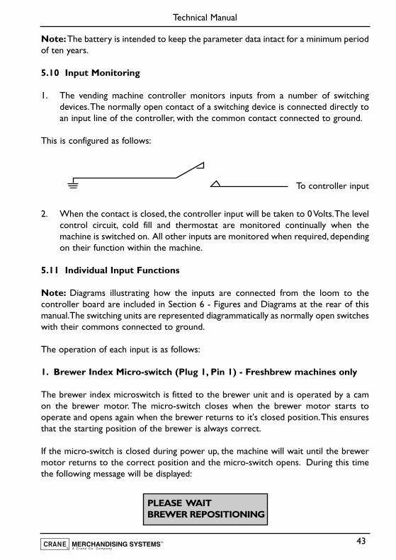
5.10 Input Monitoring
1. The vending machine controller monitors inputs from a number of switchingdevices.The normally open contact of a switching device is connected directly toan input line of the controller, with the common contact connected to ground.
This is configured as follows:
To controller input
2. When the contact is closed, the controller input will be taken to 0 Volts.The levelcontrol circuit, cold fill and thermostat are monitored continually when themachine is switched on. All other inputs are monitored when required, dependingon their function within the machine.
5.11 Individual Input Functions
Note: Diagrams illustrating how the inputs are connected from the loom to thecontroller board are included in Section 6 - Figures and Diagrams at the rear of thismanual.The switching units are represented diagrammatically as normally open switcheswith their commons connected to ground.
The operation of each input is as follows:
1. Brewer Index Micro-switch (Plug 1, Pin 1) - Freshbrew machines only
The brewer index microswitch is fitted to the brewer unit and is operated by a camon the brewer motor. The micro-switch closes when the brewer motor starts tooperate and opens again when the brewer returns to it's closed position.This ensuresthat the starting position of the brewer is always correct.
If the micro-switch is closed during power up, the machine will wait until the brewermotor returns to the correct position and the micro-switch opens. During this timethe following message will be displayed:
43
Technical Manual
PLEASE WAITBREWER REPOSITIONING
If at any time the brewer index micro-switch is closed for more than sixty seconds, thebrewer will be switched off. The message “Selection Unavailable” will be displayed if afreshbrew drink is selected.
2. Service Switch (Plug 1, Pin 2)
The service switch comprises a single pole, normally open, biased switch, which whenoperated allows one drink to be taken free of charge. This enables the operator tocheck for correct operation of the machine when it is ready for use.
3. Flush Switch (Plug 1, Pin 3)
This is a single pole, normally open, biased switch, which when operated flushes the hotwater system. Each valve is operated in sequence for a specified time (set in the‘Miscellaneous Settings Program’) and ‘rattled’ to remove any build up of limescale.Thecorresponding whipper is also operated.The brewer (where fitted) is also operated for4 (four) complete cycles.
4. View Counters Switch (Plug 1, Pin 4)
The counter switch comprises a single pole, normally open, biased switch. Whenoperated the operator is able view the vend counters by means of the arrow keys onthe keypad.
Normally, to exit from this sequence the ‘cancel’ or ‘blank’ key is pressed.A ‘time-out’feature ensures that the controller automatically reverts to standby mode if a key isnot pressed after a period of thirty seconds.
5. Counter Reset (Plug 1, Pin 5)
The counter reset switch comprises a single pole, normally open, biased switch, whichwhen operated will reset all the counters available to the operator. This input can onlybe accessed from within the main part of the “operator’s program” (i.e. not from withinan operators sub-program). Only the vend counters, which can be viewed from withinthe operator’s program, or by operating the view counters switch, will be reset.
6. Program Entry Switch (Plug 1, Pin 6)
The program entry switch input comprises a single pole, normally open, biased switch.When operated the LCD will display a ‘>’ cursor. The correct access code must beentered within five seconds of the cursor appearing, allowing access to the program.The factory pre-set for the operator code is ‘17’ whilst the engineers code is set to‘21’.
44
Technical Manual
The program entry will terminate when no button on the keypad has been pressed fora period of thirty seconds or the ‘blank’ or ‘cancel’ button is pressed.
7. Free Vend Input (Plug, 1 Pin 8)
This is a two position key switch which allows the machine to dispense free vends.
8. Coin Lines (Plug 1, Pins 9 - 15)
Seven separate input lines (one for each denomination of coin which can be accepted)are provided from the coin acceptor unit. Each input is normally high and will be pulsedlow for between 80 and 200 milliseconds on acceptance of the corresponding coin.
9. Brewer Cycle Switch (Plug 1, Pin 16) - Freshbrew machines only
The brewer cycle switch enables the operator to remove and clean the brewer topchamber.The switch is pressed and released to allow the brewer to start its cycle.Onceit has reached its open position (brewer chamber raised) it will stop allowing thechamber to be removed, cleaned and refitted. When completed the feed switch ismomentarily activated again to return the brewer to its closed position.
Note: For extra safety the mains may be switched off using the door switch when thebrewer unit reaches the top of its cycle.When the mains supply is restored, the brewerwill reposition.
10. ‘0’ Volts (Plug 1, Pins 17 and 18)
This plug is the ‘0’ volts (ground) referred to in paragraph 3.11 - Input Monitoring.
11. Thermistor Probe Input (Plug 15)
The Thermistor probe measures the temperature of the water in the boiler andconverts this into an analogue signal. This signal is used by the controller board todetermine whether or not to switch on the heater element.
If the temperature in the boiler is below the maximum boiler temperature (set in the“engineer temperature sub-program”), the heater element will be switched on. Whenthe boiler temperature reaches the maximum boiler temperature, the heater elementis switched off.When the machine is initially powered up, it will display the message:
45
Technical Manual
SORRY NOT IN USEWATER HEATING
This message will be displayed until the minimum vend temperature is reached, asdefined in the temperature sub-program in the engineer’s program.
12. Heater Tank Level Control (Plug 9, Pin 1)
This input does not operate on the same logic switching principle as those outlinedpreviously. A level control circuit on the controller board is connected between thebody of the boiler and the level probe. This sends a signal to the microprocessordependent upon the level of the water with respect to the level probe.
If the level circuit indicates low water, the controller switches on the inlet valve andthe hot fill valve. When the water reaches the level probe, the controller continues tofill the boiler for two seconds, ensuring that the tip of the level probe is completelyimmersed.
Note: There is a two minute time-out feature on the boiler filling sequence to preventthe possibility of leakage or overflow from the tank. This also prevents the heaterelement from running dry should the incoming water supply fail.
After sixty seconds of filling, the keypad is disabled and the “Low Water” messagedisplayed to prevent any further water being taken. Should the boiler still be filling aftera further sixty seconds, the machine will be completely disabled as illustrated by theflow chart on page 47.
If the water level in the boiler is low when the machine is switched on, the “Low Water”message will be displayed.The boiler will fill as described above and when the correctwater level is reached, the machine will enter “Standby” mode.
Note: In a situation of low mains water pressure and a very low boiler level at power-up, the boiler may require more than two minutes to fill.This will cause the machineto be disabled before the boiler is full. Under these circumstances, the machine can beswitched ‘off ’ and then ‘on’ again to reset the boiler time-out.
13. Electronic Waste Probe (Plug 9, Pins 3 and 4)
A level control circuit on the controller board is connected between two probeslocated in the waste tray. A signal is sent to the micro-processor depending on thelevel of the water in respect to the level probe.
If the level circuit indicates a high waste water level, the LCD will show the message:-
46
Technical Manual
SORRY NOT IN USEWASTE TRAY FULL

The machine will remain in this state until the waste bucket has been emptied.
5.12 Level Control Flow Diagram
47
Technical Manual
SWITCH OFF VALVE ANDRETURN TO STANDBY
LEVEL PROBE INPUTSLOW SIGNAL
SWITCH ONINLET VALVE
HAS VALVEBEEN ON FOR60 SECONDS?
HAS VALVEBEEN ON FOR120 SECONDS?
IS THE WATERAT THE CORRECT
LEVEL?
DISPLAYLOW WATER
MESSAGEAND
DISABLEKEYPAD
DISABLEMACHINE
NO
NO NO
YES
YES
YES
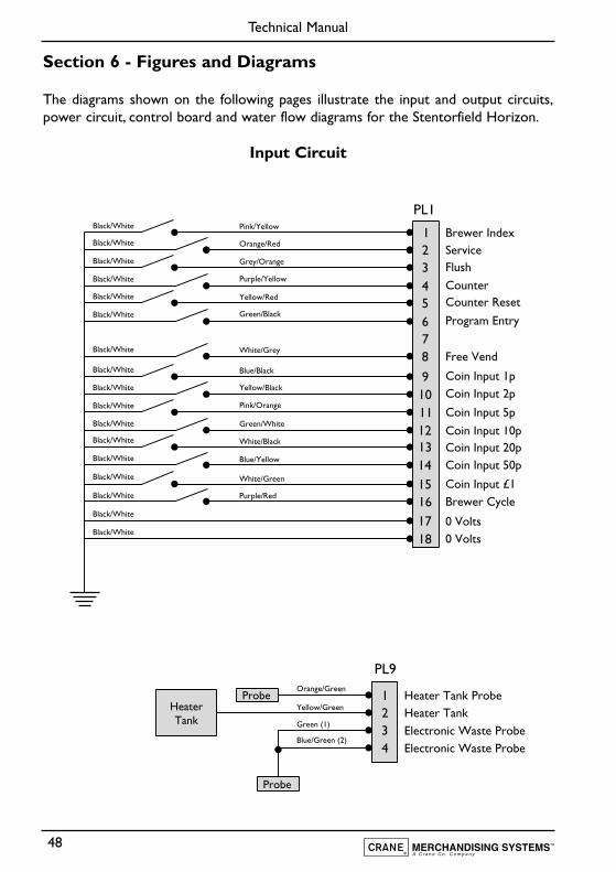
Section 6 - Figures and Diagrams
The diagrams shown on the following pages illustrate the input and output circuits,power circuit, control board and water flow diagrams for the Stentorfield Horizon.
Input Circuit
48
Technical Manual
Black/White
Black/White
Black/White
Black/White
Black/White
Orange/Red
Grey/Orange
Pink/Yellow
Black/White
Black/White
Purple/Yellow
Black/White
Black/White
Black/White Blue/Black
Black/White Yellow/Black
Black/White Pink/Orange
Black/White Green/White
Black/White White/Black
Black/White Blue/Yellow
Black/White White/Green
Black/White Purple/Red
White/Grey
Green/Black
Yellow/Red
ServiceFlush
CounterCounter Reset
Program Entry
Brewer Index
Free Vend
0 Volts
Brewer Cycle
0 Volts
Coin Input 1pCoin Input 2p
Coin Input 5p
Coin Input 10pCoin Input 20pCoin Input 50p
Coin Input £1
12345678
9101112131415161718
PL1
PL9Orange/Green
Green (1)
Blue/Green (2)
Yellow/Green
Electronic Waste Probe
Heater Tank Probe
Electronic Waste Probe
1234
Probe
Probe
HeaterTank
Heater Tank
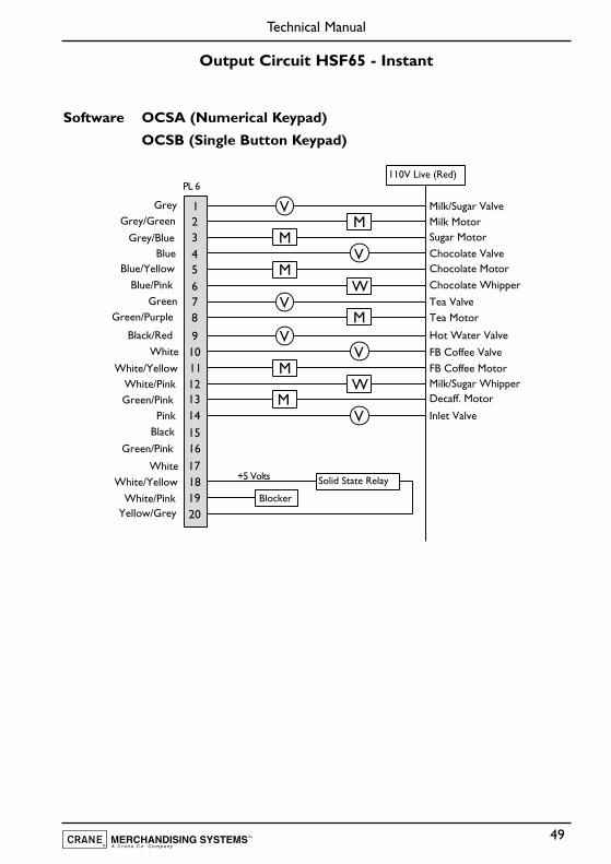
Output Circuit HSF65 - Instant
Software OCSA (Numerical Keypad)
OCSB (Single Button Keypad)
49
Technical Manual
Milk MotorGrey/GreenMilk/Sugar ValveGrey
Sugar MotorGrey/Blue
Tea Valve
Chocolate ValveBlueChocolate MotorBlue/Yellow
Chocolate WhipperBlue/PinkGreen
Tea MotorGreen/Purple
Hot Water ValveBlack/Red
FB Coffee ValveWhite
FB Coffee MotorWhite/YellowMilk/Sugar WhipperWhite/PinkDecaff. MotorGreen/PinkInlet ValvePink
Black
Green/Pink
WhiteWhite/Yellow
Yellow/Grey
12345678
91011121314151617181920
M
M
M
Solid State Relay
110V Live (Red)
Blocker
W
M
M
M
W
V
V
V
V
V
V
+5 Volts
PL 6
White/Pink
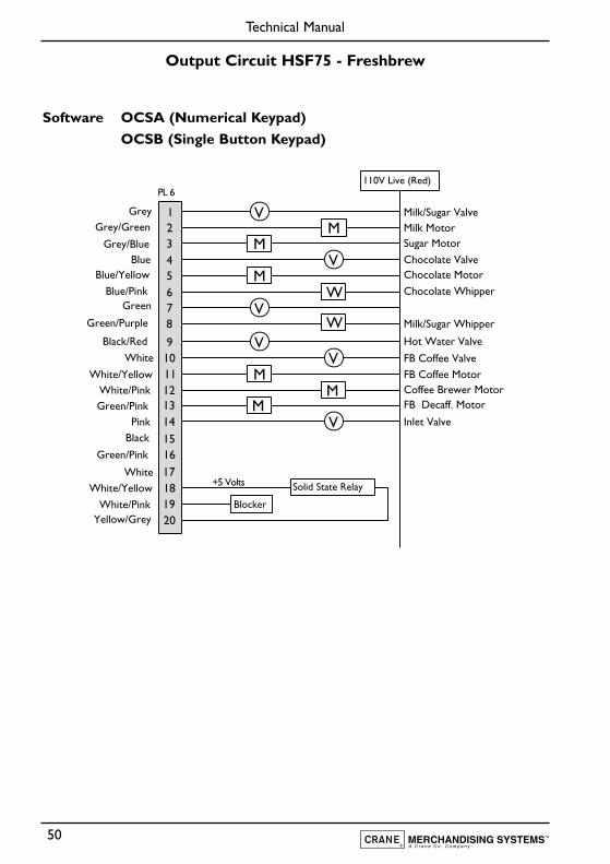
Output Circuit HSF75 - Freshbrew
Software OCSA (Numerical Keypad)
OCSB (Single Button Keypad)
50
Technical Manual
Milk MotorGrey/GreenMilk/Sugar ValveGrey
Sugar MotorGrey/BlueChocolate ValveBlueChocolate MotorBlue/Yellow
Chocolate WhipperBlue/PinkGreen
Milk/Sugar WhipperGreen/Purple
Hot Water ValveBlack/Red
FB Coffee ValveWhite
FB Coffee MotorWhite/YellowCoffee Brewer MotorWhite/PinkFB Decaff. MotorGreen/PinkInlet ValvePink
Black
Green/Pink
WhiteWhite/Yellow
Yellow/Grey
12345678
91011121314151617181920
M
M
M
Solid State Relay
110V Live (Red)
Blocker
W
M
M
M
W
V
V
V
V
V
V
+5 Volts
PL 6
White/Pink
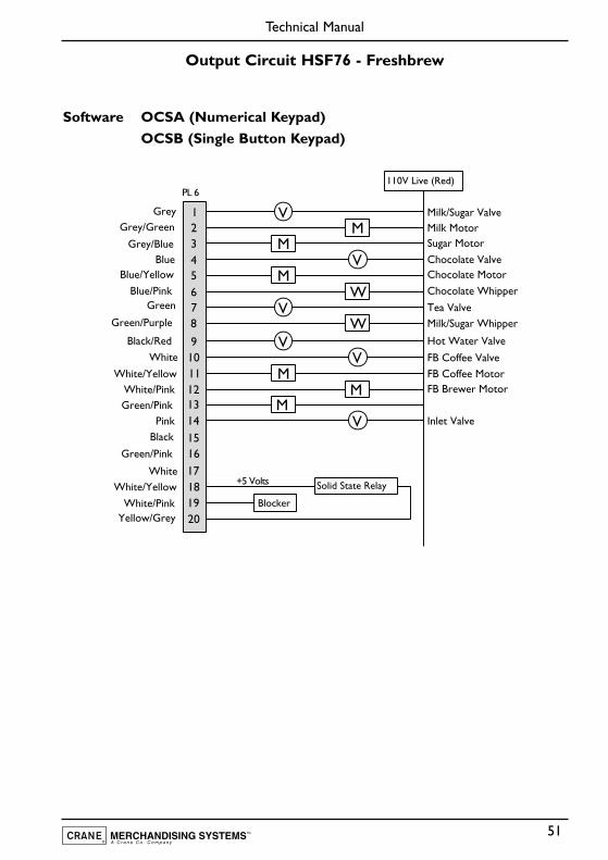
Output Circuit HSF76 - Freshbrew
Software OCSA (Numerical Keypad)
OCSB (Single Button Keypad)
51
Technical Manual
Milk MotorGrey/GreenMilk/Sugar ValveGrey
Sugar MotorGrey/Blue
Tea Valve
Chocolate ValveBlueChocolate MotorBlue/Yellow
Chocolate WhipperBlue/Pink
Milk/Sugar WhipperGreen/Purple
Hot Water ValveBlack/Red
FB Coffee ValveWhite
FB Coffee MotorWhite/YellowFB Brewer MotorWhite/Pink
Green/PinkInlet ValvePink
Black
Green/Pink
WhiteWhite/Yellow
Yellow/Grey
12345678
91011121314151617181920
M
M
M
Solid State Relay
110V Live (Red)
Blocker
W
M
M
M
W
V
V
V
V
V
V
+5 Volts
PL 6
White/Pink
Green
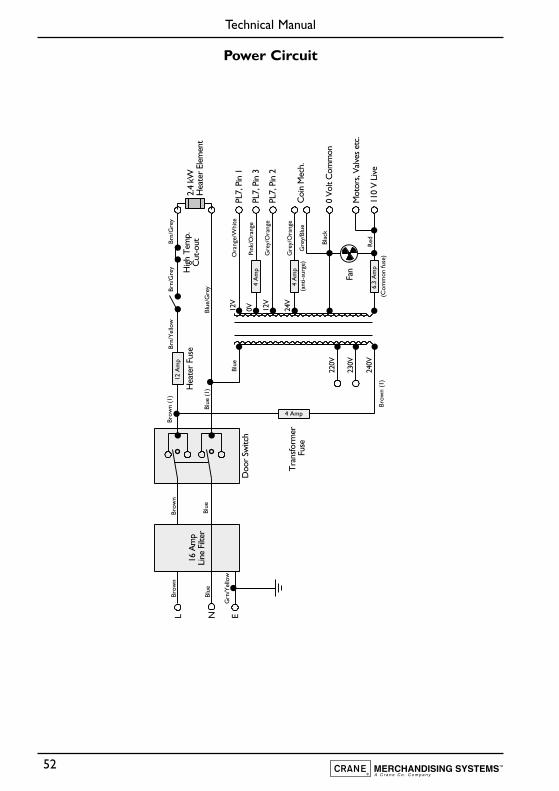
Power Circuit
52
Technical Manual
Brow
n (1
)
Brow
n (1
)
Blue
Blue
(1)
Blue
Brow
nBr
own
Blue
Grn
/Yel
low
Blue
/Gre
y
Pink
/Ora
nge
Ora
nge/
Whi
te
Gre
y/O
rang
e
Gre
y/O
rang
e
Gre
y/Bl
ue
Blac
k
Red
Brn/
Gre
yBr
n/Y
ello
wBr
n/G
rey
16 A
mp
Line
Filt
er
L N ED
oor
Switc
h
Tran
sform
er
Fuse
2.4
kWH
eate
r El
emen
tH
igh
Tem
p.C
ut-o
utH
eate
r Fu
se
PL7,
Pin
112
V
220V
230V
240V
12V
24V
0VPL
7, P
in 3
PL7,
Pin
2
Coi
n M
ech.
Mot
ors,
Valv
es e
tc.
Fan
110
V Li
ve
0 Vo
lt C
omm
on
12 A
mp
4 A
mp
4 A
mp
4 Amp
6.3
Am
p
(ant
i-sur
ge)
(Com
mon
fuse
)
Control Board
53
Technical Manual
Display Coin Mech.Communications
Keypad
PL 1
P9
P2
P6
P7
P3
. . . . . . . .
P4
CPU
Control Inputs
Level Controls
12v-0v-12v Supply
Triac Neutrals
Triac Outputs
Blocker Relay
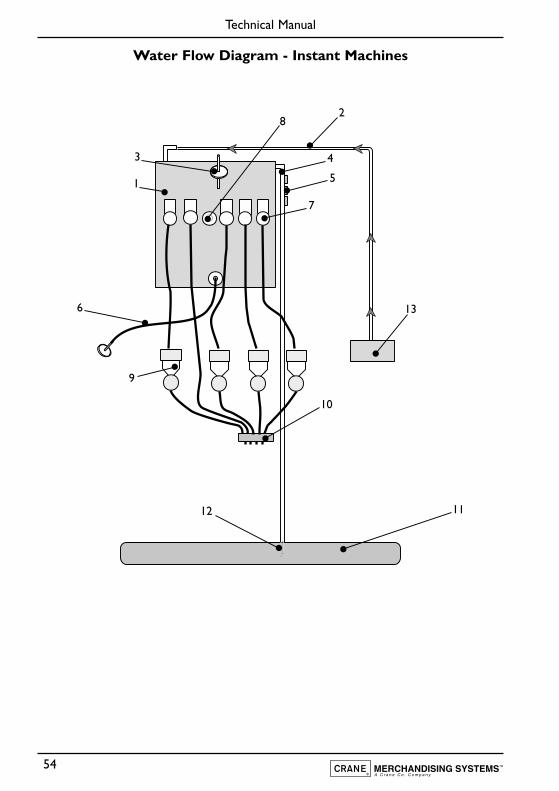
Water Flow Diagram - Instant Machines
54
Technical Manual
1
28
3 4
5
6
12
7
9
10
11
13
Water Flow Diagram - Instant Machines
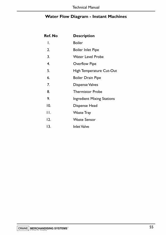
Ref. No Description
1. Boiler
2. Boiler Inlet Pipe
3. Water Level Probe
4. Overflow Pipe
5. High Temperature Cut-Out
6. Boiler Drain Pipe
7. Dispense Valves
8. Thermistor Probe
9. Ingredient Mixing Stations
10. Dispense Head
11. Waste Tray
12. Waste Sensor
13. Inlet Valve
55
Technical Manual
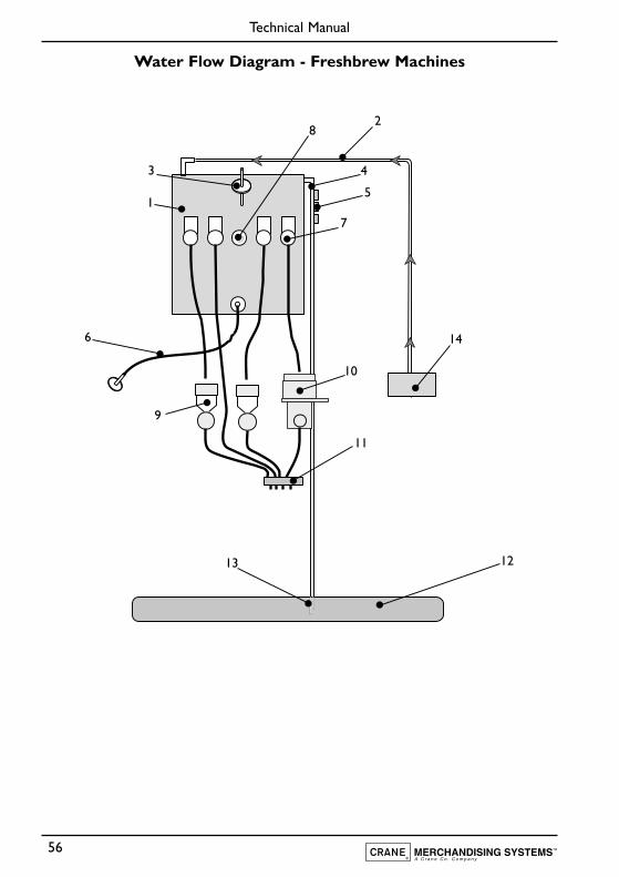
Water Flow Diagram - Freshbrew Machines
56
Technical Manual
1
28
3 4
5
6
13
7
9
10
11
12
14
Water Flow Diagram - Freshbrew Machines
Ref. No Description
1. Boiler
2. Boiler Inlet Pipe
3. Water Level Probe
4. Overflow Pipe
5. High Temperature Cut-Out
6. Boiler Drain Pipe
7. Dispense Valves
8. Thermistor Probe
9. Ingredient Mixing Stations
10. Brewer Unit - Paperless
11. Dispense Head
12. Waste Tray
13. Waste Sensor
14. Inlet Valve
57
Technical Manual
Notes
58
Technical Manual

Pipsmore Park, Bumpers Farm Industrial Estate,Chippenham,Wiltshire SN14 6NQ
Tel: +44 (0)1249 444807 Fax: +44 (0)1249 444819Email: [email protected] Website: www.cranems.co.uk
Recommended