Veljko Samardzic ME-215 Engineering Materials and Processes
Gas Flame and Arc Processes
Chapter 31
Veljko Samardzic ME-215 Engineering Materials and Processes
31.1 Oxyfuel-Gas Welding
Veljko Samardzic ME-215 Engineering Materials and Processes
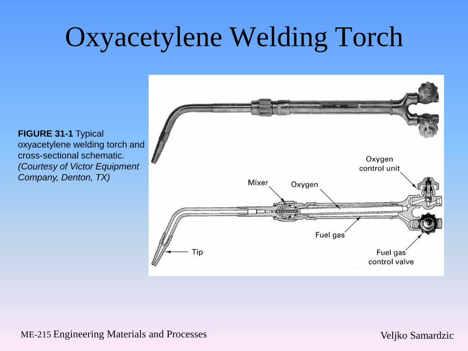
Oxyacetylene Welding Torch
FIGURE 31-1 Typical
oxyacetylene welding torch and
cross-sectional schematic.
(Courtesy of Victor Equipment
Company, Denton, TX)
Veljko Samardzic ME-215 Engineering Materials and Processes
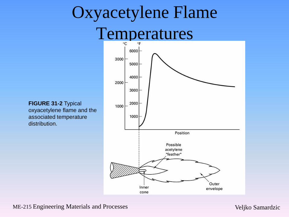
Oxyacetylene Flame
Temperatures
FIGURE 31-2 Typical
oxyacetylene flame and the
associated temperature
distribution.
Veljko Samardzic ME-215 Engineering Materials and Processes
Oxyfuel-gas Welding
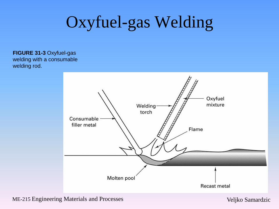
FIGURE 31-3 Oxyfuel-gas
welding with a consumable
welding rod.
Veljko Samardzic ME-215 Engineering Materials and Processes
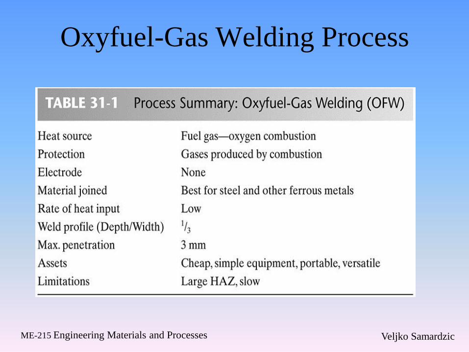
Oxyfuel-Gas Welding Process
Veljko Samardzic ME-215 Engineering Materials and Processes
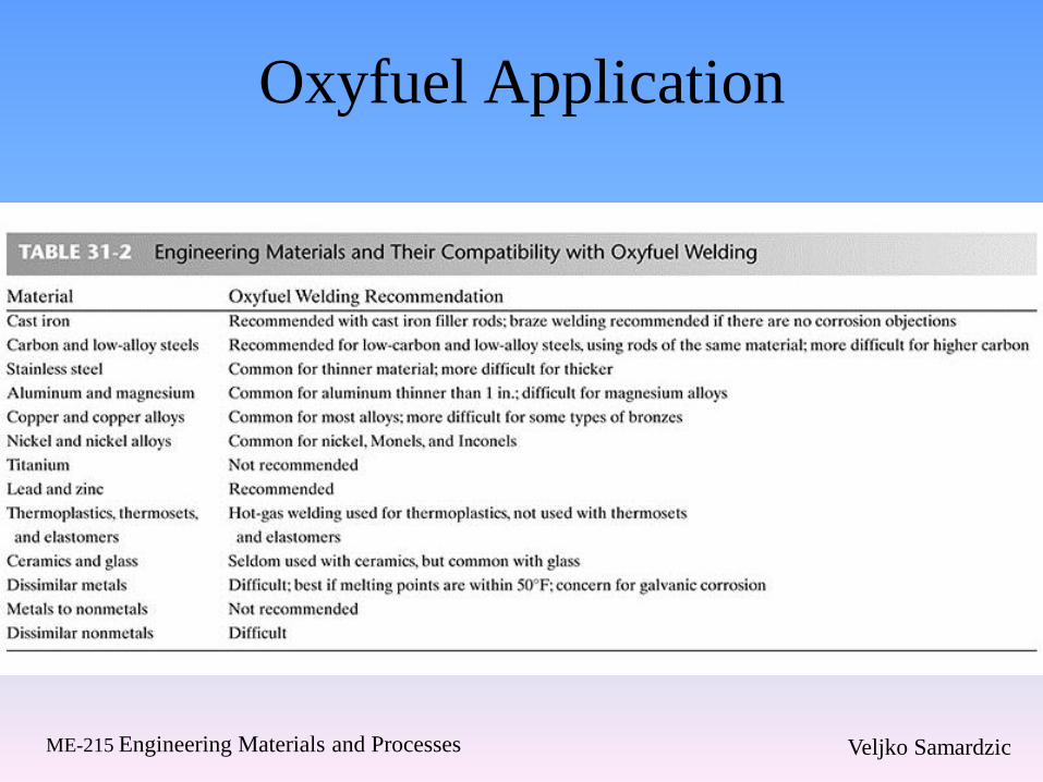
Oxyfuel Application

Veljko Samardzic ME-215 Engineering Materials and Processes
31.2 Oxygen Torch Cutting
Veljko Samardzic ME-215 Engineering Materials and Processes
Flame Cutting
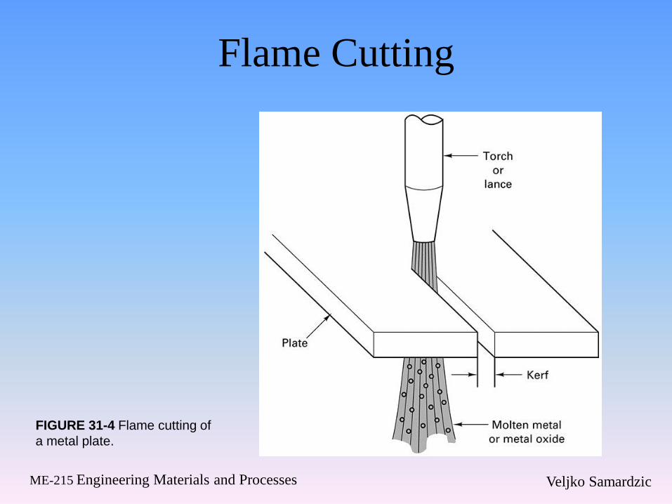
FIGURE 31-4 Flame cutting of
a metal plate.
Veljko Samardzic ME-215 Engineering Materials and Processes
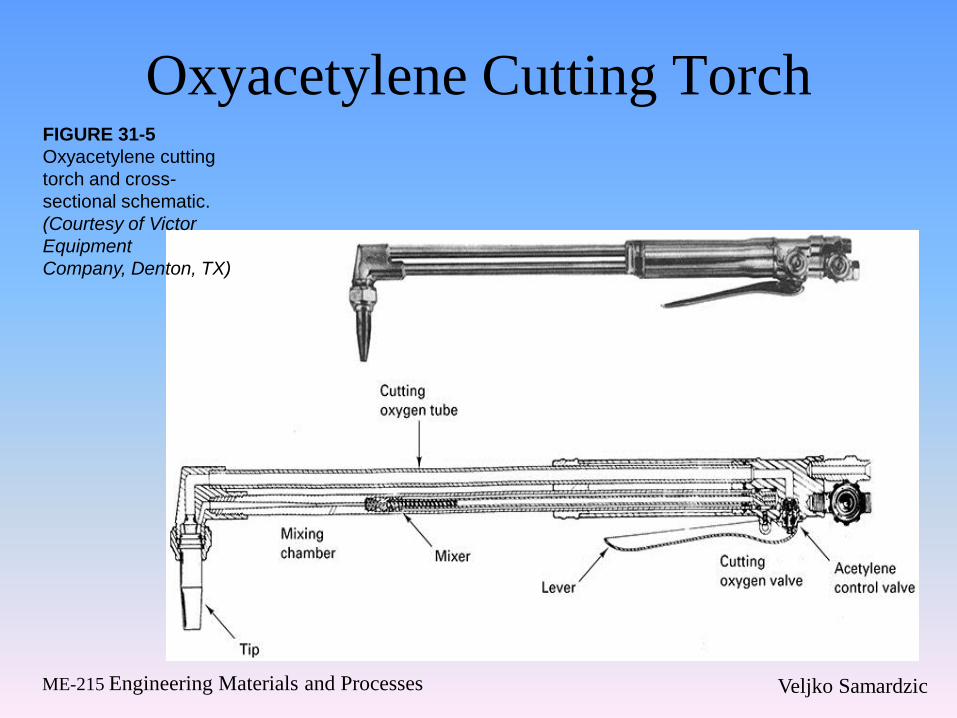
Oxyacetylene Cutting Torch FIGURE 31-5
Oxyacetylene cutting
torch and cross-
sectional schematic.
(Courtesy of Victor
Equipment
Company, Denton, TX)
Veljko Samardzic ME-215 Engineering Materials and Processes
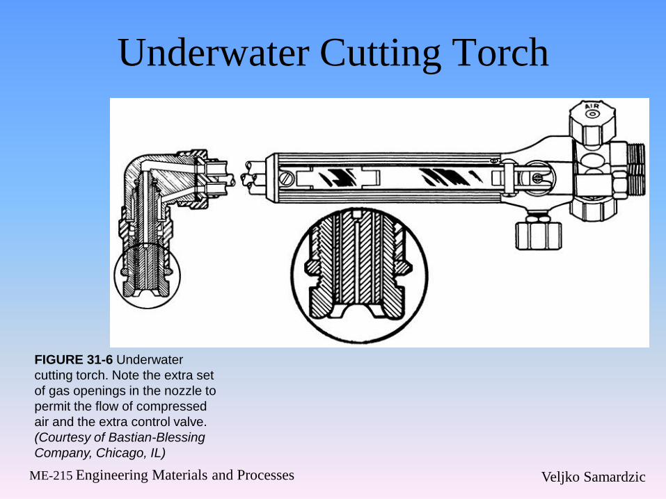
Underwater Cutting Torch
FIGURE 31-6 Underwater
cutting torch. Note the extra set
of gas openings in the nozzle to
permit the flow of compressed
air and the extra control valve.
(Courtesy of Bastian-Blessing
Company, Chicago, IL)
Veljko Samardzic ME-215 Engineering Materials and Processes
31.3 Flame Straightening
Veljko Samardzic ME-215 Engineering Materials and Processes
Flame Straightening
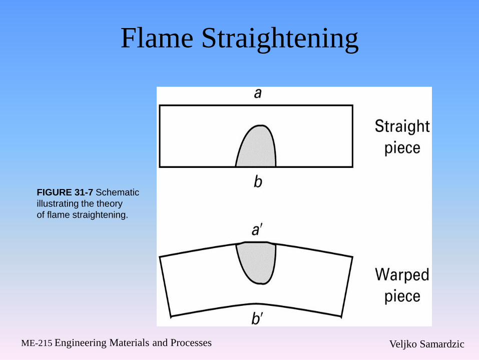
FIGURE 31-7 Schematic
illustrating the theory
of flame straightening.
Veljko Samardzic ME-215 Engineering Materials and Processes
31.4 Arc Welding
Veljko Samardzic ME-215 Engineering Materials and Processes
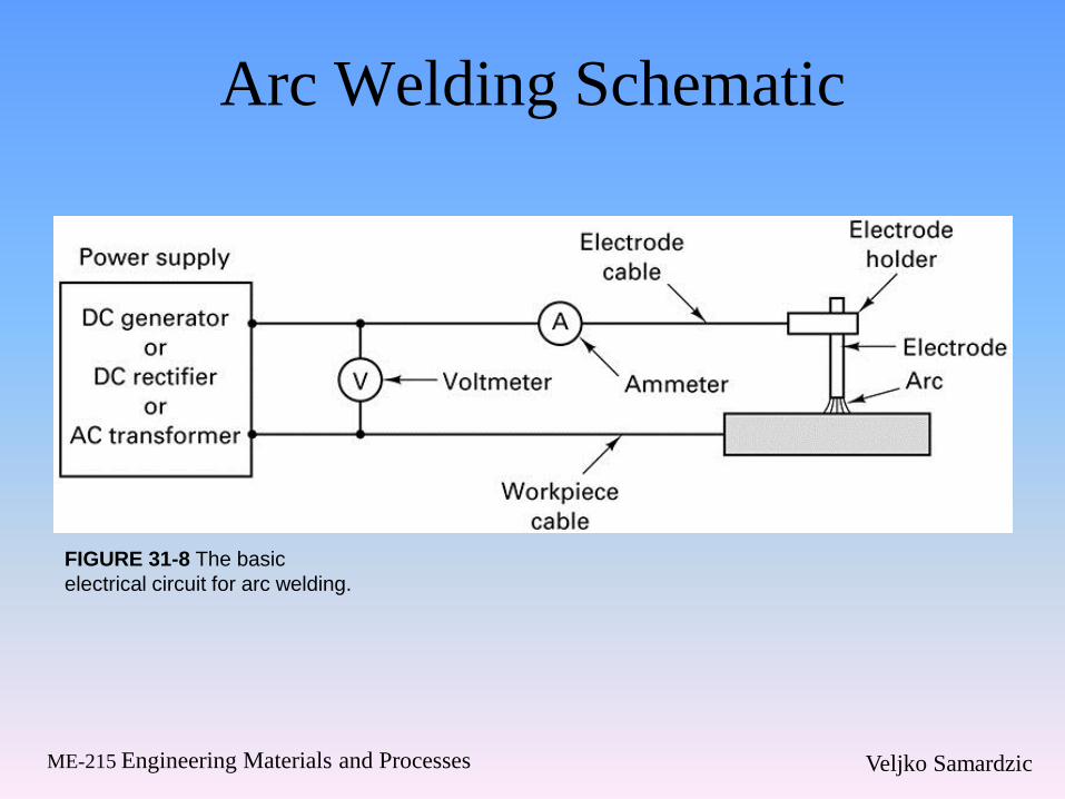
Arc Welding Schematic
FIGURE 31-8 The basic
electrical circuit for arc welding.
Veljko Samardzic ME-215 Engineering Materials and Processes
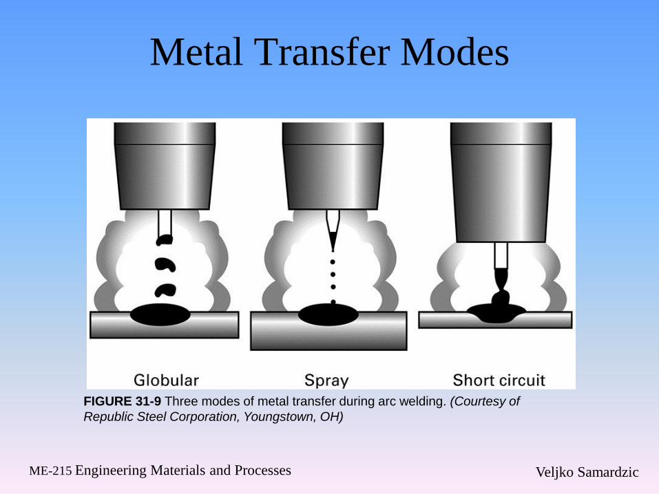
Metal Transfer Modes
FIGURE 31-9 Three modes of metal transfer during arc welding. (Courtesy of
Republic Steel Corporation, Youngstown, OH)
Veljko Samardzic ME-215 Engineering Materials and Processes
31.5 Consumable-Electrode Arc
Welding
Veljko Samardzic ME-215 Engineering Materials and Processes
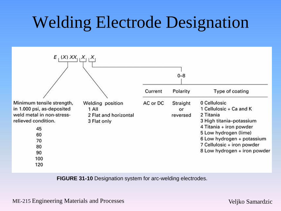
Welding Electrode Designation
FIGURE 31-10 Designation system for arc-welding electrodes.
Veljko Samardzic ME-215 Engineering Materials and Processes
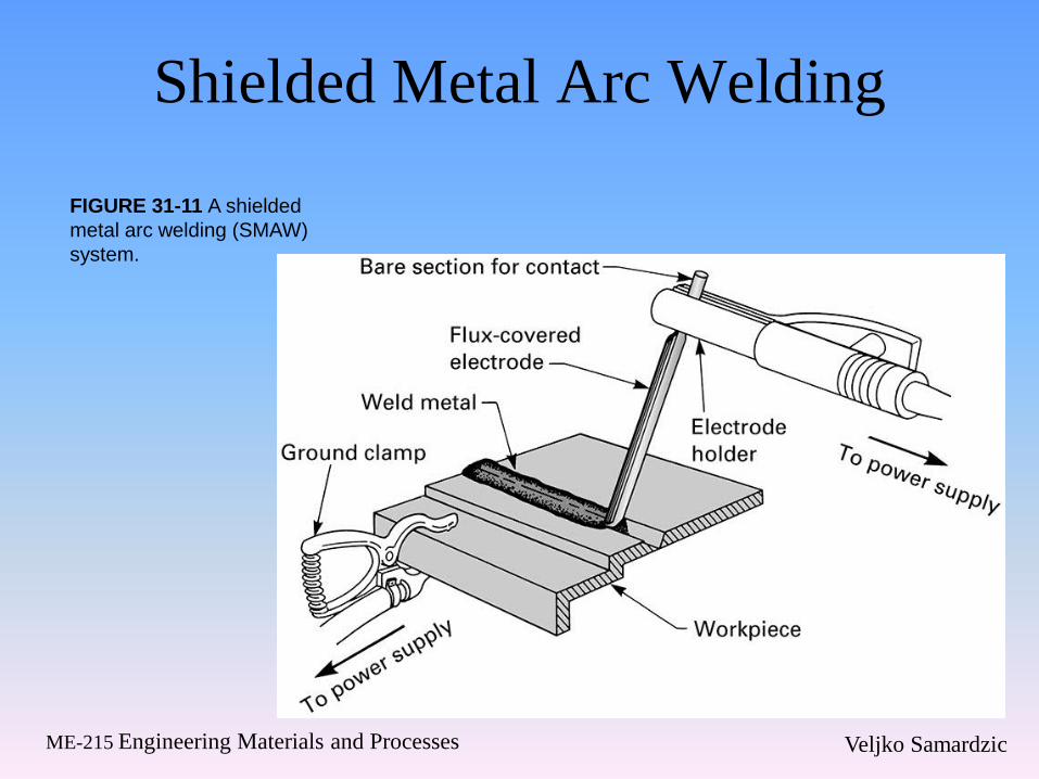
Shielded Metal Arc Welding
FIGURE 31-11 A shielded
metal arc welding (SMAW)
system.
Veljko Samardzic ME-215 Engineering Materials and Processes
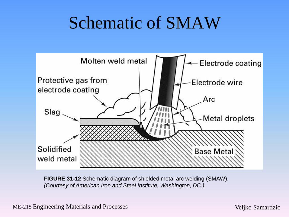
Schematic of SMAW
FIGURE 31-12 Schematic diagram of shielded metal arc welding (SMAW).
(Courtesy of American Iron and Steel Institute, Washington, DC.)
Veljko Samardzic ME-215 Engineering Materials and Processes
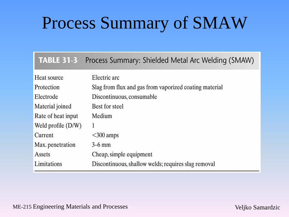
Process Summary of SMAW
Veljko Samardzic ME-215 Engineering Materials and Processes
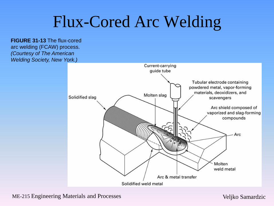
Flux-Cored Arc Welding FIGURE 31-13 The flux-cored
arc welding (FCAW) process.
(Courtesy of The American
Welding Society, New York.)
Veljko Samardzic ME-215 Engineering Materials and Processes
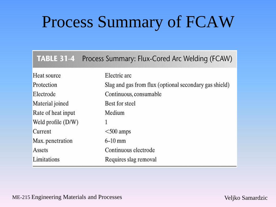
Process Summary of FCAW
Veljko Samardzic ME-215 Engineering Materials and Processes
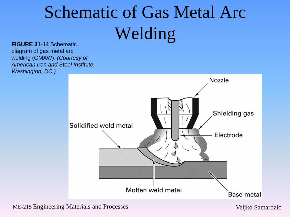
Schematic of Gas Metal Arc
Welding FIGURE 31-14 Schematic
diagram of gas metal arc
welding (GMAW). (Courtesy of
American Iron and Steel Institute,
Washington, DC.)
Veljko Samardzic ME-215 Engineering Materials and Processes
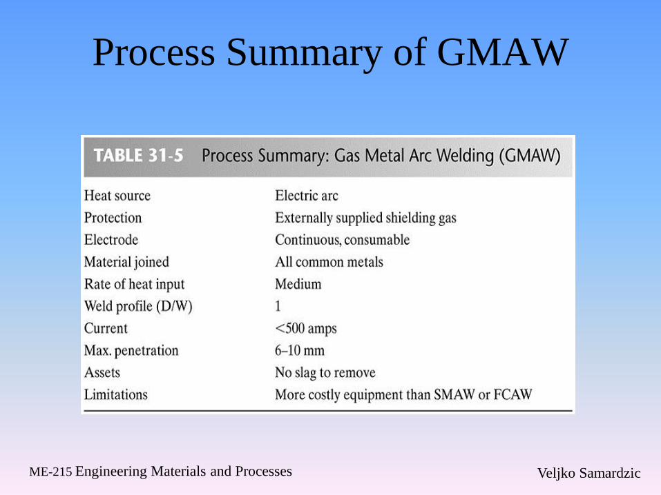
Process Summary of GMAW
Veljko Samardzic ME-215 Engineering Materials and Processes
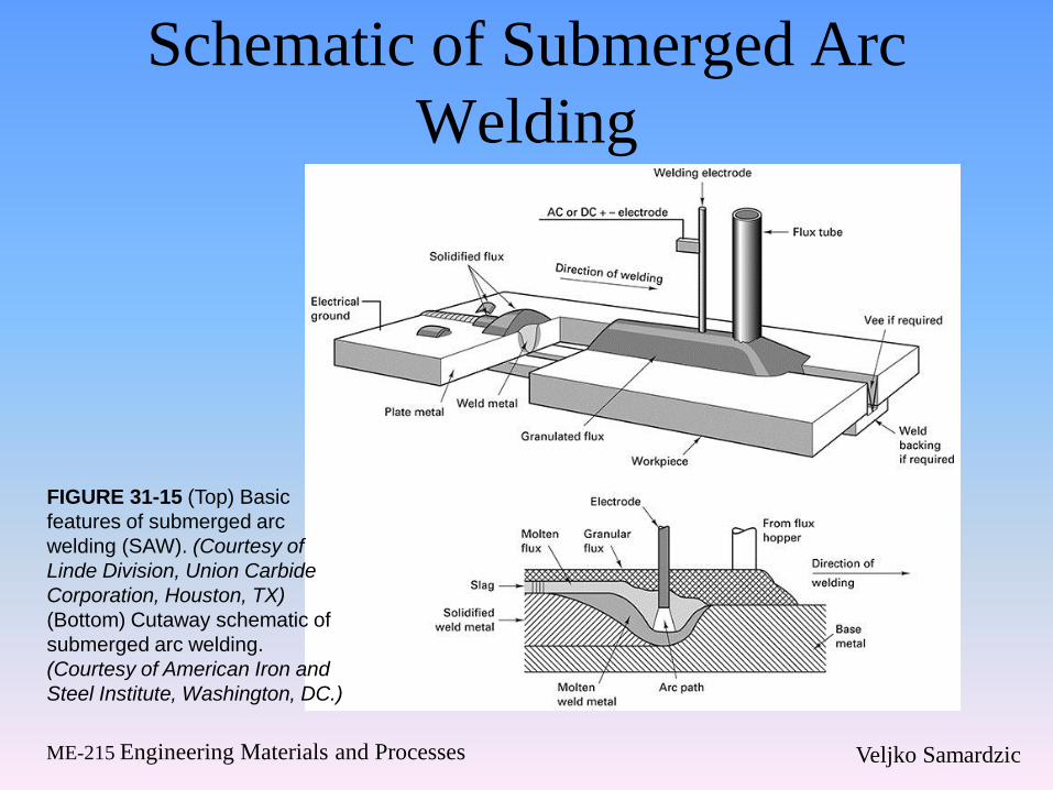
Schematic of Submerged Arc
Welding
FIGURE 31-15 (Top) Basic
features of submerged arc
welding (SAW). (Courtesy of
Linde Division, Union Carbide
Corporation, Houston, TX)
(Bottom) Cutaway schematic of
submerged arc welding.
(Courtesy of American Iron and
Steel Institute, Washington, DC.)
Veljko Samardzic ME-215 Engineering Materials and Processes
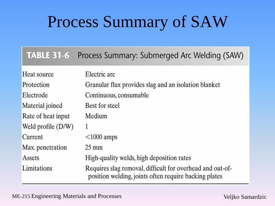
Process Summary of SAW
Veljko Samardzic ME-215 Engineering Materials and Processes
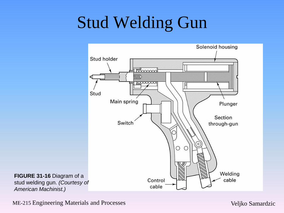
Stud Welding Gun
FIGURE 31-16 Diagram of a
stud welding gun. (Courtesy of
American Machinist.)
Veljko Samardzic ME-215 Engineering Materials and Processes
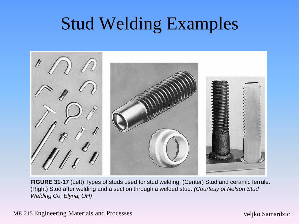
Stud Welding Examples
FIGURE 31-17 (Left) Types of studs used for stud welding. (Center) Stud and ceramic ferrule.
(Right) Stud after welding and a section through a welded stud. (Courtesy of Nelson Stud
Welding Co, Elyria, OH)
Veljko Samardzic ME-215 Engineering Materials and Processes
31.6 Nonconsumable-Electrode Arc
Welding
Veljko Samardzic ME-215 Engineering Materials and Processes
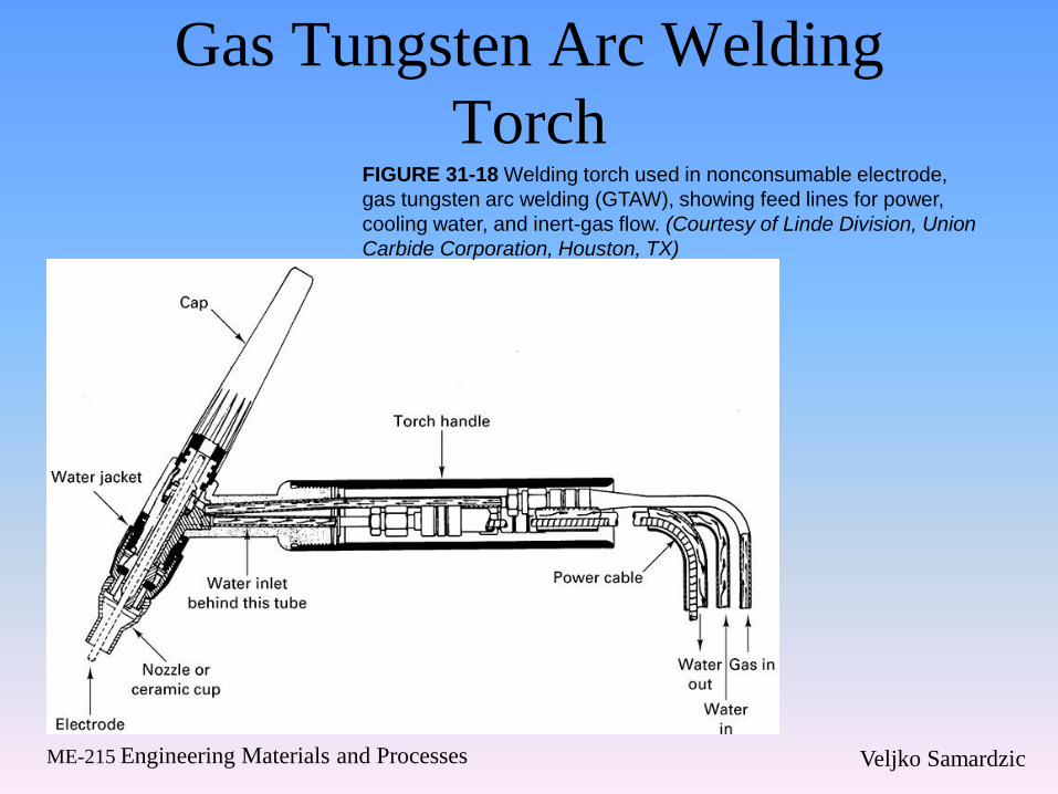
Gas Tungsten Arc Welding
Torch FIGURE 31-18 Welding torch used in nonconsumable electrode,
gas tungsten arc welding (GTAW), showing feed lines for power,
cooling water, and inert-gas flow. (Courtesy of Linde Division, Union
Carbide Corporation, Houston, TX)
Veljko Samardzic ME-215 Engineering Materials and Processes
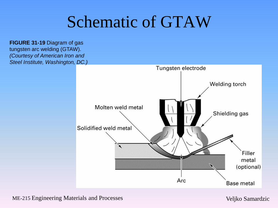
Schematic of GTAW FIGURE 31-19 Diagram of gas
tungsten arc welding (GTAW).
(Courtesy of American Iron and
Steel Institute, Washington, DC.)
Veljko Samardzic ME-215 Engineering Materials and Processes
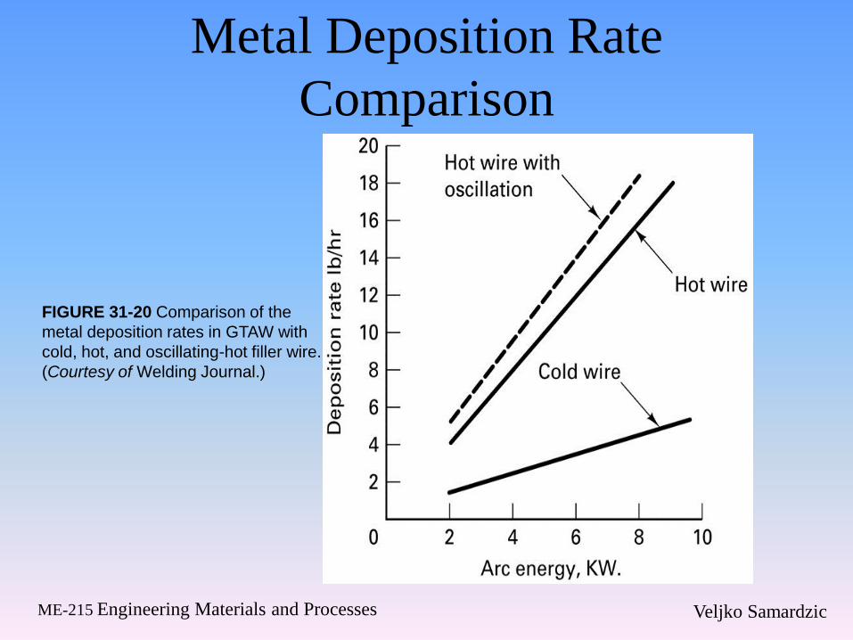
Metal Deposition Rate
Comparison
FIGURE 31-20 Comparison of the
metal deposition rates in GTAW with
cold, hot, and oscillating-hot filler wire.
(Courtesy of Welding Journal.)
Veljko Samardzic ME-215 Engineering Materials and Processes
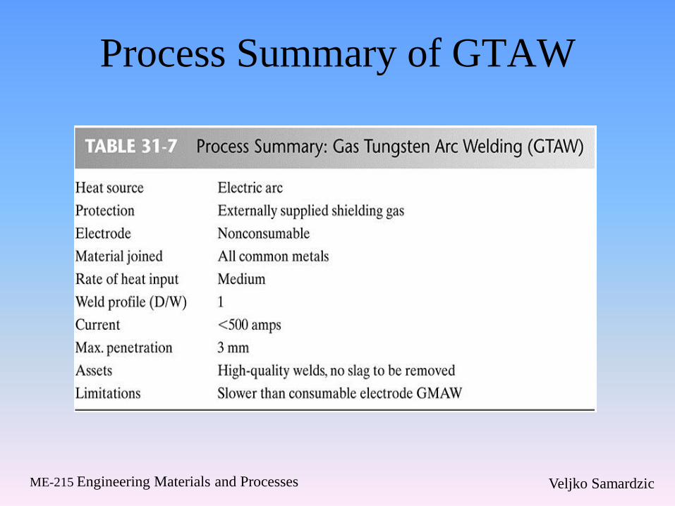
Process Summary of GTAW
Veljko Samardzic ME-215 Engineering Materials and Processes
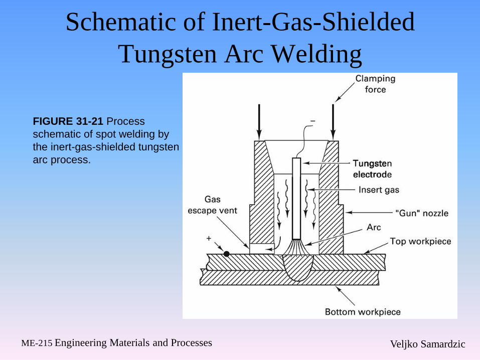
Schematic of Inert-Gas-Shielded
Tungsten Arc Welding
FIGURE 31-21 Process
schematic of spot welding by
the inert-gas-shielded tungsten
arc process.
Veljko Samardzic ME-215 Engineering Materials and Processes
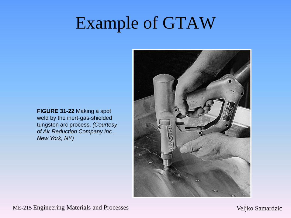
Example of GTAW
FIGURE 31-22 Making a spot
weld by the inert-gas-shielded
tungsten arc process. (Courtesy
of Air Reduction Company Inc.,
New York, NY)
Veljko Samardzic ME-215 Engineering Materials and Processes
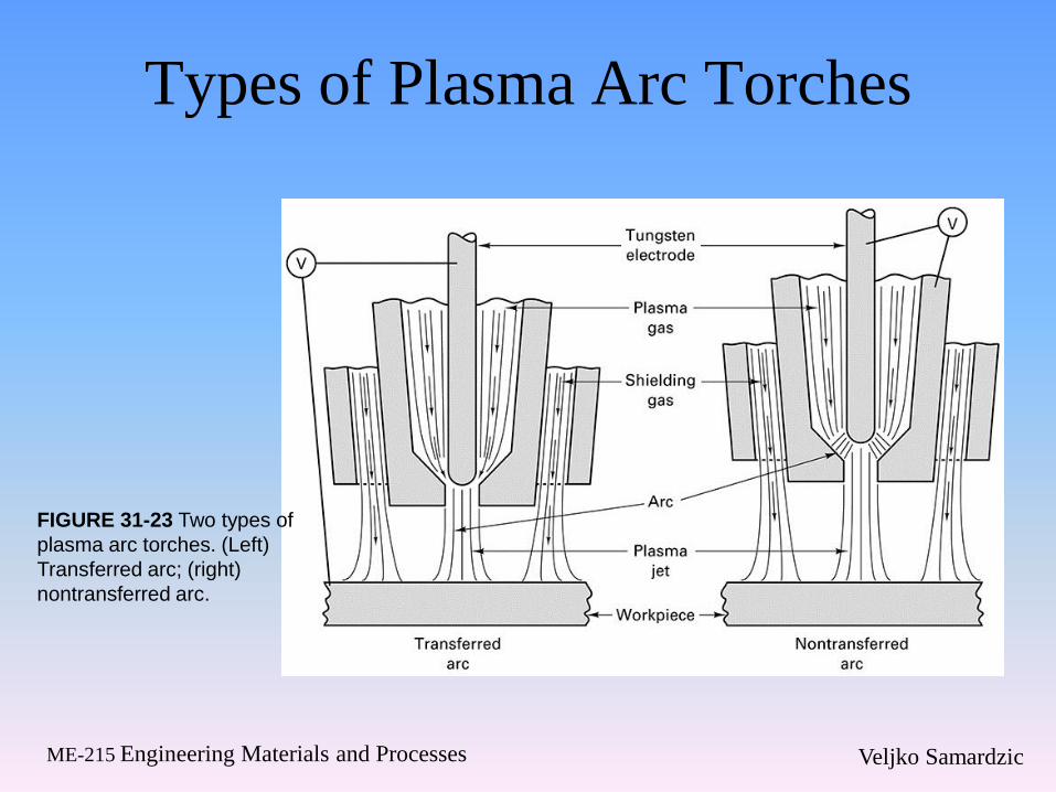
Types of Plasma Arc Torches
FIGURE 31-23 Two types of
plasma arc torches. (Left)
Transferred arc; (right)
nontransferred arc.
Veljko Samardzic ME-215 Engineering Materials and Processes
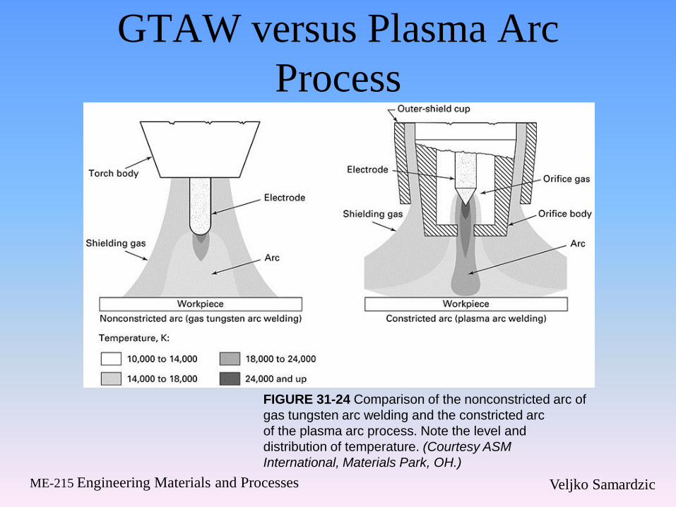
GTAW versus Plasma Arc
Process
FIGURE 31-24 Comparison of the nonconstricted arc of
gas tungsten arc welding and the constricted arc
of the plasma arc process. Note the level and
distribution of temperature. (Courtesy ASM
International, Materials Park, OH.)
Veljko Samardzic ME-215 Engineering Materials and Processes
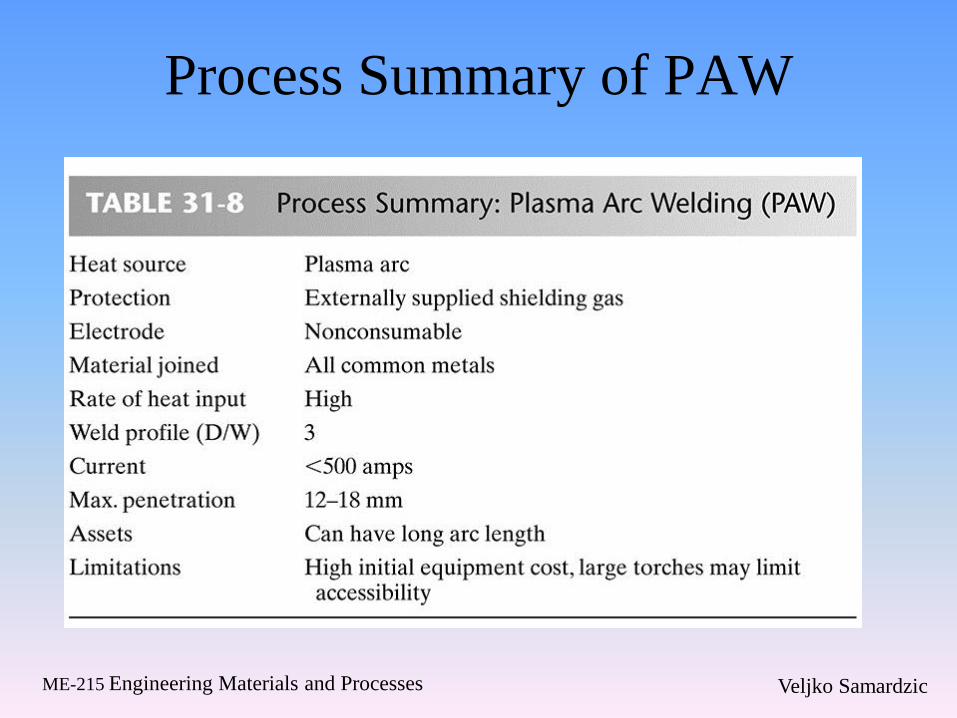
Process Summary of PAW
Veljko Samardzic ME-215 Engineering Materials and Processes
31.7 Welding Equipment
Veljko Samardzic ME-215 Engineering Materials and Processes
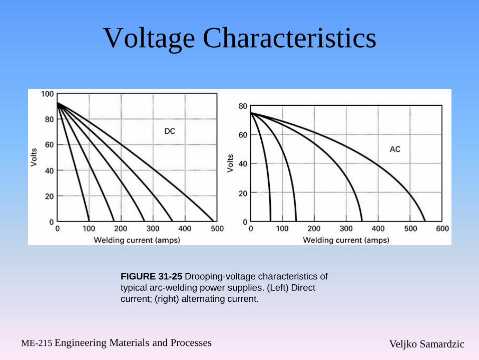
Voltage Characteristics
FIGURE 31-25 Drooping-voltage characteristics of
typical arc-welding power supplies. (Left) Direct
current; (right) alternating current.
Veljko Samardzic ME-215 Engineering Materials and Processes
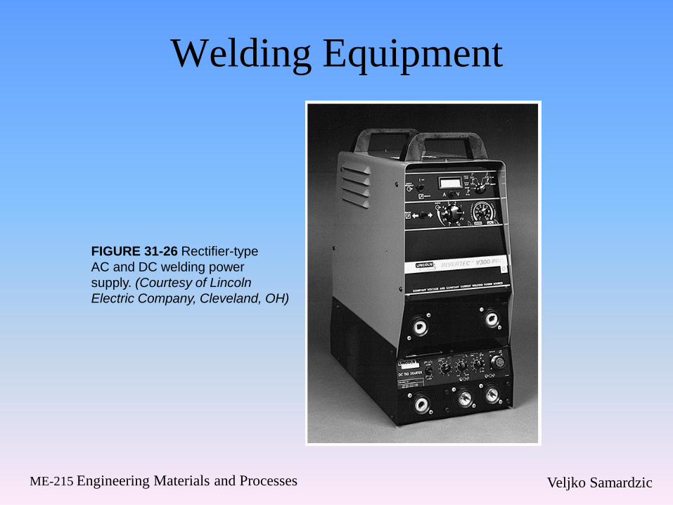
Welding Equipment
FIGURE 31-26 Rectifier-type
AC and DC welding power
supply. (Courtesy of Lincoln
Electric Company, Cleveland, OH)
Veljko Samardzic ME-215 Engineering Materials and Processes
31.8 Arc Cutting
Veljko Samardzic ME-215 Engineering Materials and Processes
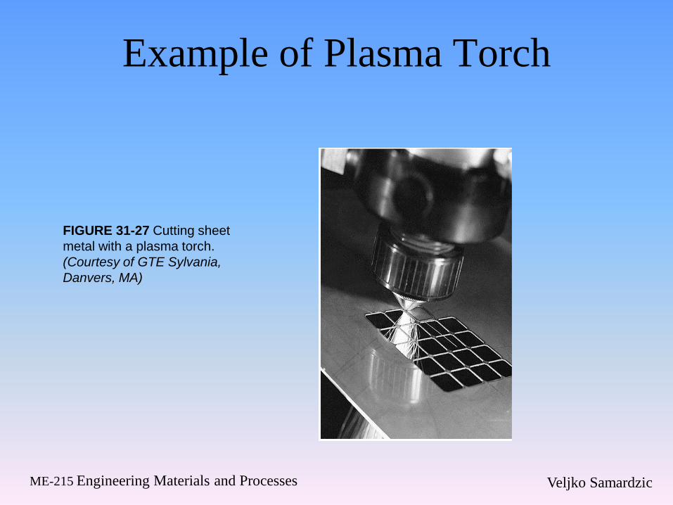
Example of Plasma Torch
FIGURE 31-27 Cutting sheet
metal with a plasma torch.
(Courtesy of GTE Sylvania,
Danvers, MA)
Veljko Samardzic ME-215 Engineering Materials and Processes
31.9 Metallurgical and Heat Effects
in Thermal Cutting
Veljko Samardzic ME-215 Engineering Materials and Processes
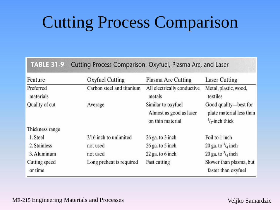
Cutting Process Comparison
Recommended