PLCopen For Efficiency in Automation
Technical Paper
PLCopen Technical Committee
Function Blocks for motion control: Part 2 - Extensions
PLCopen Working Draft, Version 0.99, release for comments
DISCLAIMER OF WARRANTIES
THIS DOCUMENT IS PROVIDED ON AN “AS IS” BASIS AND MAY BE SUBJECT TO FUTURE ADDITIONS, MODIFICATIONS, OR CORRECTIONS. PLCOPEN HEREBY DISCLAIMS ALL WARRANTIES OF ANY KIND, EXPRESS OR IMPLIED, INCLUDING ANY WARRANTY OF MERCHANTABILITY OR FITNESS FOR A PARTICULAR PURPOSE, FOR THIS DOCUMENT. IN NO EVENT WILL PLCOPEN BE RESPONSIBLE FOR ANY LOSS OR DAMAGE ARISING OUT OR RESULTING FROM ANY DEFECT, ERROR OR OMISSION IN THIS DOCUMENT OR FROM ANYONE’S USE OF OR RELIANCE ON THIS DOCUMENT.
Copyright © 2002, 2003, 2004 by PLCopen. All rights reserved.
Date: April 16, 2004
PLCopen For Efficiency in Automation
TC2 - Task Force Motion Control © PLCopen –2002, 2003, 2004 Part 2 – Extensions – V. 0.99 April 16, 2004 page 2/ 38
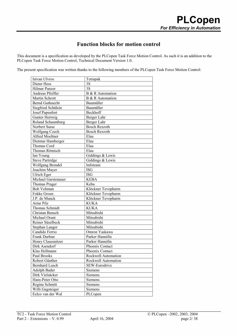
Function blocks for motion control
This document is a specification as developed by the PLCopen Task Force Motion Control. As such it is an addition to the PLCopen Task Force Motion Control, Technical Document Version 1.0. The present specification was written thanks to the following members of the PLCopen Task Force Motion Control:
Istvan Ulvros Tetrapak Dieter Hess 3S Hilmar Panzer 3S Andreas Pfeiffer B & R Automation Martin Schrott B & R Automation Bernd Gutknecht Baumüller Siegfried Schülein Baumüller Josef Papenfort Beckhoff Gunter Hertwig Berger Lahr Roland Schaumburg Berger Lahr Norbert Sasse Bosch Rexroth Wolfgang Czech Bosch Rexroth Alfred Moeltner Elau Dietmar Hamberger Elau Thomas Cord Elau Thomas Römisch Elau Ian Young Giddings & Lewis Steve Partridge Giddings & Lewis Wolfgang Brendel Infoteam Joachim Mayer ISG Ulrich Eger ISG Michael Garstenauer KEBA Thomas Prager Keba Bob Veltman Klöckner Tevopharm Fokke Groen Klöckner Tevopharm J.P. de Munck Klöckner Tevopharm Artur Pilz KUKA Thomas Schmidt KUKA Christan Bensch Mitsubishi Michael Orant Mitsubishi Reiner Süselbeck Mitsubishi Stephan Langer Mitsubishi Candido Ferrio Omron Yaskawa Frank Durban Parker Hannifin Henry Claussnitzer Parker Hannifin Dirk Asendorf Phoenix Contact Klas Hellmann Phoenix Contact Paul Brooks Rockwell Automation Robert Günther Rockwell Automation Bernhard Lusch SEW-Eurodrive Adolph Bader Siemens Dirk Vielsäcker Siemens Hans-Peter Otto Siemens Regina Schmitt Siemens Willi Gagsteiger Siemens Eelco van der Wal PLCopen
PLCopen For Efficiency in Automation
TC2 - Task Force Motion Control © PLCopen –2002, 2003, 2004 Part 2 – Extensions – V. 0.99 April 16, 2004 page 3/ 38
Change Status List: Version number
Date Change comment
V 0.1 September 21, 2000 Preliminary version – result of the decision on the meeting of July 13 & 14, 2000, to create this extended set
V 0.2 May 9 + 10, 2001 Meeting MoveContinuous removed form 0.99 and put in here V 0.3 July 16, 2002 Added the decisions as made at the meeting of June 11 and 12, 2002,
Amsterdam. V 0.4 September 23 + 24, 2002 Comments during meeting Sept. 23 and 24, 2002 V 0.5 December 9 + 10, 2002 Comments during meeting Dec. 9 and 10, 2002 V 0.6 March 11 + 12, 2003 Comments during meeting March 11 and 12, 2003 – not distributed V 0.7 May 15, 2003 Comments during meeting May 14 & 15, 2003 V 0.7a July 9, 2003 Added homework in preparation of meeting July V 0.8 July 18, 2003 Result of Meeting July V 08A September 4, 2003 Split between Part2, 3 and 4. Added State Diagram V 0.9 September 24, 2003 Result of the meeting Sept. 22 – 24, and editing by EvdWal V 0.91 November 21, 2003 Result of feedback –edited by EvdW V 0.92 December 18, 2003 Results of feedback on V 0.91 – edited by EvdW V 0.93 February 3 / March 22, 2004 Generation of version for final meeting by EvdW V 0.94 March 30, 31, 2004 Results of the meeting at Berger Lahr V 0.95 April 13, 2004 Further editing by EvdW V 0.99 April 16, 2004 Release for comments – by EvdW
PLCopen For Efficiency in Automation
TC2 - Task Force Motion Control © PLCopen –2002, 2003, 2004 Part 2 – Extensions – V. 0.99 April 16, 2004 page 4/ 38
Table of Contents
1. GENERAL INTRODUCTION ............................................................................................................................... 7 2. OVERVIEW OF THE DEFINED EXTENDED FUNCTION BLOCKS: .......................................................... 8 2.1. GENERAL REMARKS TO THE FB BEHAVIOR ............................................................................................................. 9
2.1.1. Behavior of Busy output ................................................................................................................................. 9 3. STATE DIAGRAM................................................................................................................................................ 10 4. DEFINED USER DERIVED DATATYPES........................................................................................................ 12 5. FUNCTION BLOCKS – EXTENSIONS FOR MOTION CONTROL ............................................................. 13 5.1. TOUCHPROBE........................................................................................................................................................ 13 5.2. ABORTTRIGGER .................................................................................................................................................... 15 5.3. READDIGITALINPUT ............................................................................................................................................. 16 5.4. READDIGITALOUTPUT .......................................................................................................................................... 17 5.5. WRITEDIGITALOUTPUT ........................................................................................................................................ 18 5.6. SETPOSITION......................................................................................................................................................... 19 5.7. SETOVERRIDE ....................................................................................................................................................... 20 5.8. READACTUALVELOCITY....................................................................................................................................... 22 5.9. READACTUALTORQUE.......................................................................................................................................... 23 5.10. TORQUECONTROL............................................................................................................................................. 24 5.11. DIGITAL CAM SWITCH ...................................................................................................................................... 25 5.12. GEARINPOS....................................................................................................................................................... 29 6. APPENDIX A – COMPLIANCE STATEMENT................................................................................................ 32 6.1. APPENDIX A - SUPPORTED DERIVED DATATYPES................................................................................................. 33 6.2. APPENDIX A - OVERVIEW OF THE FUNCTION BLOCKS .......................................................................................... 34
6.2.1. TouchProbe .................................................................................................................................................. 34 6.2.2. AbortTrigger................................................................................................................................................. 34 6.2.3. ReadDigitalInput .......................................................................................................................................... 35 6.2.4. ReadDigitalOutput ....................................................................................................................................... 35 6.2.5. WriteDigitalOutput....................................................................................................................................... 35 6.2.6. SetPosition.................................................................................................................................................... 36 6.2.7. SetOverride................................................................................................................................................... 36 6.2.8. ReadActualVelocity ...................................................................................................................................... 36 6.2.9. ReadActualTorque........................................................................................................................................ 37 6.2.10. TorqueControl .............................................................................................................................................. 37 6.2.11. Digital Cam Switch ...................................................................................................................................... 37 6.2.12. GearInPos .................................................................................................................................................... 38
PLCopen For Efficiency in Automation
TC2 - Task Force Motion Control © PLCopen –2002, 2003, 2004 Part 2 – Extensions – V. 0.99 April 16, 2004 page 5/ 38
Table of Figures
FIGURE 1: FB STATE BEHAVIOR ........................................................................................................................... 11 FIGURE 2: TIMING EXAMPLE TOUCHPROBE ................................................................................................... 14 FIGURE 3: GRAPHICAL EXPLANATION OF MC_SETOVERRIDE ................................................................ 21 FIGURE 4: EXAMPLE OF DIGITALCAMSWITCH............................................................................................... 27 FIGURE 5: DETAILED DESCRIPTION OF SWITCH01........................................................................................ 27 FIGURE 6: EXAMPLE IN NEGATIVE DIRECTION.............................................................................................. 28
PLCopen For Efficiency in Automation
TC2 - Task Force Motion Control © PLCopen –2002, 2003, 2004 Part 2 – Extensions – V. 0.99 April 16, 2004 page 6/ 38
Table of Tables
TABLE 1: OVERVIEW OF THE DEFINED FUNCTION BLOCKS........................................................................ 8 TABLE 2: SUPPORTED DERIVED DATATYPES................................................................................................... 33 TABLE 3: SHORT OVERVIEW OF THE FUNCTION BLOCKS.......................................................................... 34
PLCopen For Efficiency in Automation
TC2 - Task Force Motion Control © PLCopen –2002, 2003, 2004 Part 2 – Extensions – V. 0.99 April 16, 2004 page 7/ 38
1. General Introduction At the end of 2001, PLCopen released the first release of the specification of an independent library of function blocks for motion control. It included motion functionality for single axes and multiple axes, several administrative tasks, as well as a state diagram. This specification provides the user a standard command set and structure independent of the underlying architecture. This structure can be used on many platforms and architectures. In this way one can decide which architecture will be used at a later stage of the development cycle. Advantages for the machine builder are, amongst others, lower costs for supporting the different platforms and the freedom to develop application software in a more independent way, without limiting the productivity of the machine. In addition to those benefits, system maintenance is easier and the education period is shorter. This is a major step forward, and is more and more accepted by both users as well as suppliers. With the release of part 1, it was understood that additional functionality was needed. Part 1 provides the basis for a set of specifications, which add to each other: Part 1 - PLCopen Function Blocks for Motion Control Part 2 - PLCopen Motion Control Extensions Part 3 - PLCopen Motion Control User Guidelines The PLCopen Motion Control Extensions specification, Part 2, as well as the User Guidelines, Part 3, are additions to the PLCopen Function Blocks for Motion Control, and should not be seen as stand alone documents. The objective of this PLCopen Task Force Motion Control Extensions is: To define a set of extensions to the v1.0 ‘PLCopen Function Blocks for Motion Control’ specification, which will serve the majority of user’s application, needs.
PLCopen For Efficiency in Automation
TC2 - Task Force Motion Control © PLCopen –2002, 2003, 2004 Part 2 – Extensions – V. 0.99 April 16, 2004 page 8/ 38
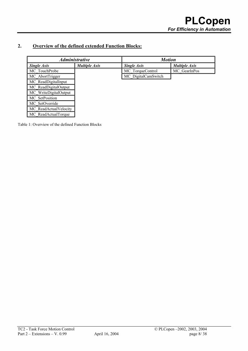
2. Overview of the defined extended Function Blocks:
Administrative Motion Single Axis Multiple Axis Single Axis Multiple Axis MC_TouchProbe MC_TorqueControl MC_GearInPos MC_AbortTrigger MC_DigitalCamSwitch MC_ReadDigitalInput MC_ReadDigitalOutput MC_WriteDigitalOutput MC_SetPosition MC_SetOverride MC_ReadActualVelocity MC_ReadActualTorque
Table 1: Overview of the defined Function Blocks
PLCopen For Efficiency in Automation
TC2 - Task Force Motion Control © PLCopen –2002, 2003, 2004 Part 2 – Extensions – V. 0.99 April 16, 2004 page 9/ 38
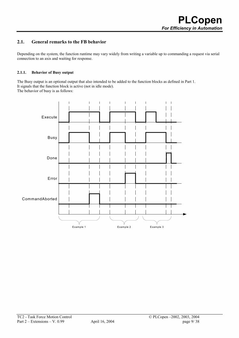
2.1. General remarks to the FB behavior Depending on the system, the function runtime may vary widely from writing a variable up to commanding a request via serial connection to an axis and waiting for response. 2.1.1. Behavior of Busy output The Busy output is an optional output that also intended to be added to the function blocks as defined in Part 1. It signals that the function block is active (not in idle mode). The behavior of busy is as follows:
Execute
Busy
Done
Error
CommandAborted
Example 1 Example 2 Example 3
PLCopen For Efficiency in Automation
TC2 - Task Force Motion Control © PLCopen –2002, 2003, 2004 Part 2 – Extensions – V. 0.99 April 16, 2004 page 10/ 38
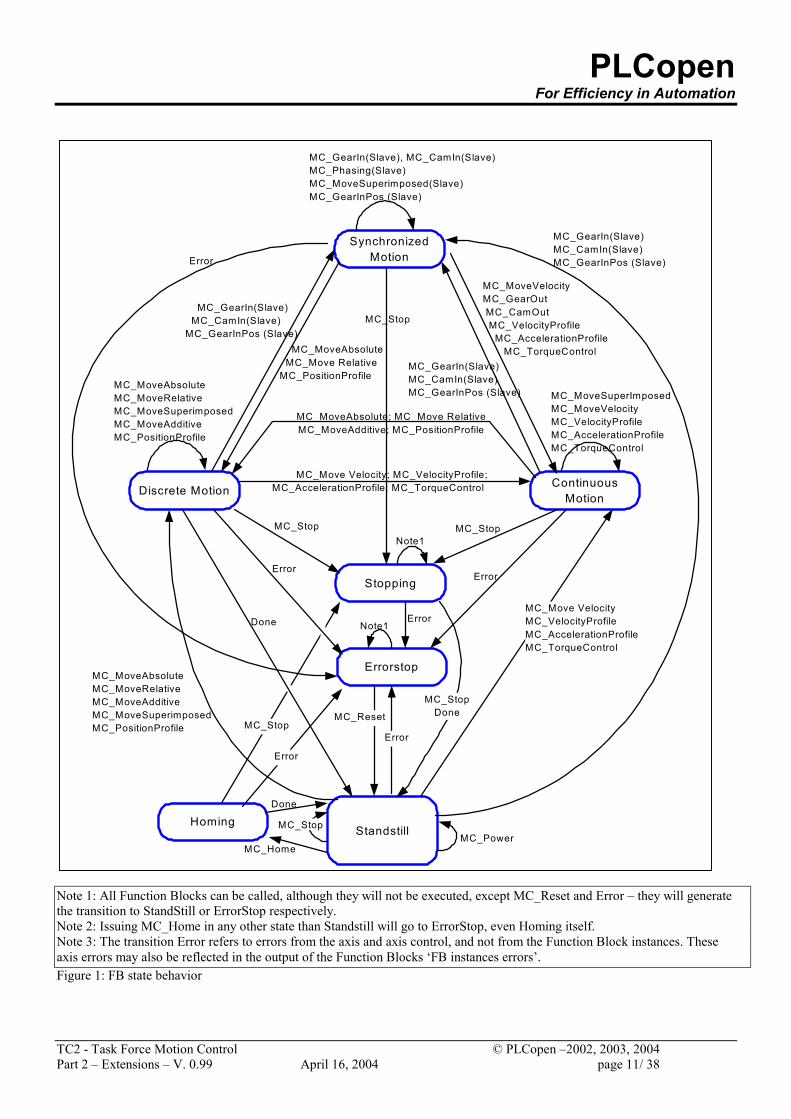
3. State Diagram The following state diagram is based on the version as defined in ‘Part 1 – Function Blocks for Motion Control’. For the extensions, there is only one Function Block added: MC_TorqueControl. It can be called in the states Continuous Motion, Discrete Motion, Synchronized Motion, and Stand Still. It leads every time to the state Continuous Motion, even if there is only a torque without a motion. . Function Blocks not listed in the state diagram do not effect the State Diagram, meaning that, whenever they are called the state does not change. They are: MC_TouchProbe, MC_AbortTrigger, MC_ReadDigitalInput, MC_ReadDigitalOutput, MC_WriteDigitalOutput, MC_SetPosition, MC_SetOverride, MC_ReadActualVelocity, MC_ReadActualTorque, MC_DigitalCamSwitch.
PLCopen For Efficiency in Automation
TC2 - Task Force Motion Control © PLCopen –2002, 2003, 2004 Part 2 – Extensions – V. 0.99 April 16, 2004 page 11/ 38
Note 1: All Function Blocks can be called, although they will not be executed, except MC_Reset and Error – they will generate the transition to StandStill or ErrorStop respectively. Note 2: Issuing MC_Home in any other state than Standstill will go to ErrorStop, even Homing itself. Note 3: The transition Error refers to errors from the axis and axis control, and not from the Function Block instances. These axis errors may also be reflected in the output of the Function Blocks ‘FB instances errors’. Figure 1: FB state behavior
MC_MoveVelocityMC_GearOut MC_CamOut MC_VelocityProfile MC_AccelerationProfile MC_TorqueControl
Homing
Errorstop
Stopping
Discrete Motion ContinuousMotion
Standstill
Note1
MC_MoveSuperImposedMC_MoveVelocityMC_VelocityProfileMC_AccelerationProfileMC_TorqueControl
MC_Stop
MC_Move VelocityMC_VelocityProfileMC_AccelerationProfileMC_TorqueControl
Note1Error
MC_StopDoneMC_Reset
MC_Power
MC_Stop
MC_Stop
Done
MC_Home
Error
MC_Stop
Done
MC_MoveAbsoluteMC_MoveRelativeMC_MoveAdditiveMC_MoveSuperimposedMC_PositionProfile
MC_MoveAbsoluteMC_MoveRelativeMC_MoveSuperimposedMC_MoveAdditiveMC_PositionProfile
Error
Error
MC_MoveAbsolute; MC_Move RelativeMC_MoveAdditive; MC_PositionProfile
SynchronizedMotion
MC_GearIn(Slave), MC_CamIn(Slave)MC_Phasing(Slave)MC_MoveSuperimposed(Slave)MC_GearInPos (Slave)
MC_MoveAbsolute MC_Move RelativeMC_PositionProfile
MC_GearIn(Slave)MC_CamIn(Slave)MC_GearInPos (Slave)Error
MC_Stop
Error
MC_GearIn(Slave)MC_CamIn(Slave)MC_GearInPos (Slave)
MC_Move Velocity; MC_VelocityProfile;MC_AccelerationProfile; MC_TorqueControl
MC_GearIn(Slave) MC_CamIn(Slave)MC_GearInPos (Slave)
PLCopen For Efficiency in Automation
TC2 - Task Force Motion Control © PLCopen –2002, 2003, 2004 Part 2 – Extensions – V. 0.99 April 16, 2004 page 12/ 38
4. Defined User Derived Datatypes The objective of this PLCopen Task Force Motion Control Extensions is defined in chapter 1 General Introduction. To reach this objective, it is necessary to define additional reference types. These references are a representation of the ‘objects’ or devices, which are not necessarily a part of the process image. As a general rule, these new reference datatypes are thought to be used in the same way like the AXIS_REF, meaning that i.e. parameters can be read with similar Function blocks having for instance an INPUT_REF instead of AXIS_REF and using the according I/O parameters. With the definition of these reference structures (or datatypes), there are FBs defined which give access to the referenced data. The following reference datatypes are defined within this document:
Defined datatype(s) Relevant Function Block(s) TRIGGER_REF is a supplier specific data type that contains information about the trigger input, e.g.:
a. Location to the trigger source b. Additional detection pattern information (positive, negative, both, edge,
level, pattern recognition, etc)
MC_TouchProbe MC_AbortTrigger
INPUT_REF is a supplier specific data type that contains a reference to a specific set of inputs, which may be virtual, meaning outside the declaration part..
MC_ReadDigitalInput
OUTPUT_REF is a supplier specific structure linked to the (physical) outputs MC_DigitalCamSwitch MC_ReadDigitalOutput MC_WriteDigitalOutput
CAMSWITCH_REF is a supplier specific reference to the pattern data. MC_DigitalCamSwitch TRACK_REF is supplier specific structure containing information about a track, e.g. the compensations (A track is a set of switches related to one output).
MC_DigitalCamSwitch
PLCopen For Efficiency in Automation
TC2 - Task Force Motion Control © PLCopen –2002, 2003, 2004 Part 2 – Extensions – V. 0.99 April 16, 2004 page 13/ 38
5. Function Blocks – Extensions for Motion Control
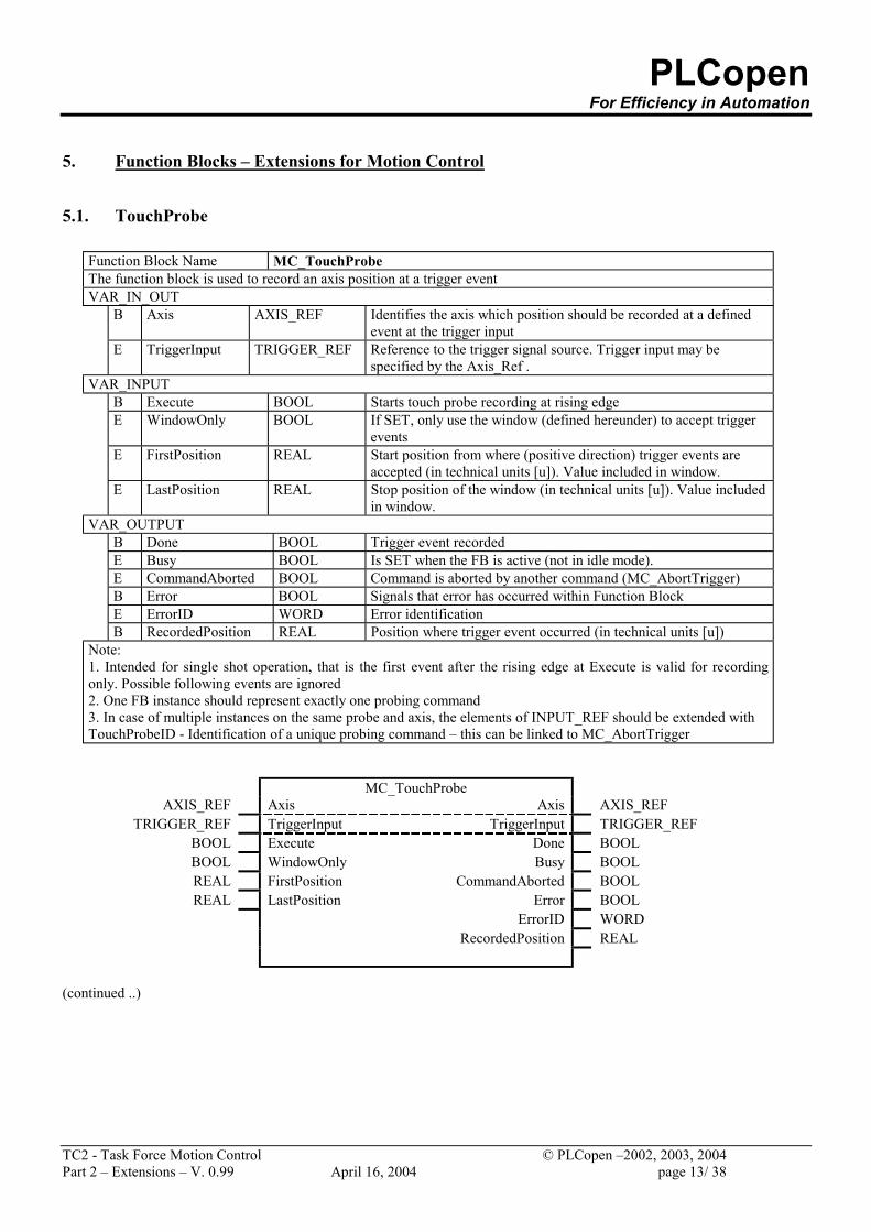
5.1. TouchProbe
Function Block Name MC_TouchProbe The function block is used to record an axis position at a trigger event VAR_IN_OUT
B Axis AXIS_REF Identifies the axis which position should be recorded at a defined event at the trigger input
E TriggerInput TRIGGER_REF Reference to the trigger signal source. Trigger input may be specified by the Axis_Ref .
VAR_INPUT B Execute BOOL Starts touch probe recording at rising edge E WindowOnly BOOL If SET, only use the window (defined hereunder) to accept trigger
events E FirstPosition REAL Start position from where (positive direction) trigger events are
accepted (in technical units [u]). Value included in window. E LastPosition REAL Stop position of the window (in technical units [u]). Value included
in window. VAR_OUTPUT
B Done BOOL Trigger event recorded E Busy BOOL Is SET when the FB is active (not in idle mode). E CommandAborted BOOL Command is aborted by another command (MC_AbortTrigger) B Error BOOL Signals that error has occurred within Function Block E ErrorID WORD Error identification B RecordedPosition REAL Position where trigger event occurred (in technical units [u])
Note: 1. Intended for single shot operation, that is the first event after the rising edge at Execute is valid for recording only. Possible following events are ignored 2. One FB instance should represent exactly one probing command 3. In case of multiple instances on the same probe and axis, the elements of INPUT_REF should be extended with TouchProbeID - Identification of a unique probing command – this can be linked to MC_AbortTrigger
MC_TouchProbe AXIS_REF Axis Axis AXIS_REF
TRIGGER_REF TriggerInput TriggerInput TRIGGER_REF BOOL Execute Done BOOL BOOL WindowOnly Busy BOOL REAL FirstPosition CommandAborted BOOL REAL LastPosition Error BOOL
ErrorID WORD RecordedPosition REAL
(continued ..)
PLCopen For Efficiency in Automation
TC2 - Task Force Motion Control © PLCopen –2002, 2003, 2004 Part 2 – Extensions – V. 0.99 April 16, 2004 page 14/ 38
Done
FALSE
TRUE
Execute
FALSE
TRUE
FALSE
TRUE
t
t
t
t
TriggerInput.Signal
Axis.Position
FirstPosition
RecordedPosition
LastPosition
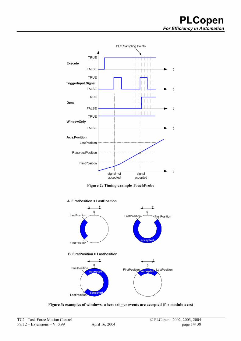
PLC Sampling Points
signal notaccepted
signalaccepted
WindowOnly
FALSE
TRUE
t
Figure 2: Timing example TouchProbe
accepted
+-
0FirstPosition LastPosition
+-
0
FirstPosition
LastPosition
accepted
+-
0LastPosition
accepted
A. FirstPosition < LastPosition
B. FirstPosition > LastPosition
FirstPosition
+-
0FirstPosition
LastPositionaccepted
accepted
Figure 3: examples of windows, where trigger events are accepted (for modulo axes)
PLCopen For Efficiency in Automation
TC2 - Task Force Motion Control © PLCopen –2002, 2003, 2004 Part 2 – Extensions – V. 0.99 April 16, 2004 page 15/ 38
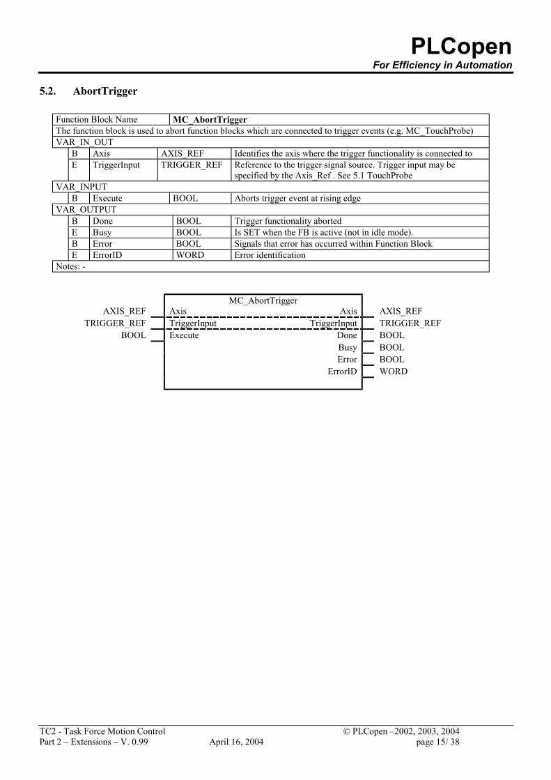
5.2. AbortTrigger
Function Block Name MC_AbortTrigger The function block is used to abort function blocks which are connected to trigger events (e.g. MC_TouchProbe) VAR_IN_OUT
B Axis AXIS_REF Identifies the axis where the trigger functionality is connected to E TriggerInput TRIGGER_REF Reference to the trigger signal source. Trigger input may be
specified by the Axis_Ref . See 5.1 TouchProbe VAR_INPUT
B Execute BOOL Aborts trigger event at rising edge VAR_OUTPUT
B Done BOOL Trigger functionality aborted E Busy BOOL Is SET when the FB is active (not in idle mode). B Error BOOL Signals that error has occurred within Function Block E ErrorID WORD Error identification
Notes: -
MC_AbortTrigger AXIS_REF Axis Axis AXIS_REF
TRIGGER_REF TriggerInput TriggerInput TRIGGER_REF BOOL Execute Done BOOL
Busy BOOL Error BOOL ErrorID WORD
PLCopen For Efficiency in Automation
TC2 - Task Force Motion Control © PLCopen –2002, 2003, 2004 Part 2 – Extensions – V. 0.99 April 16, 2004 page 16/ 38
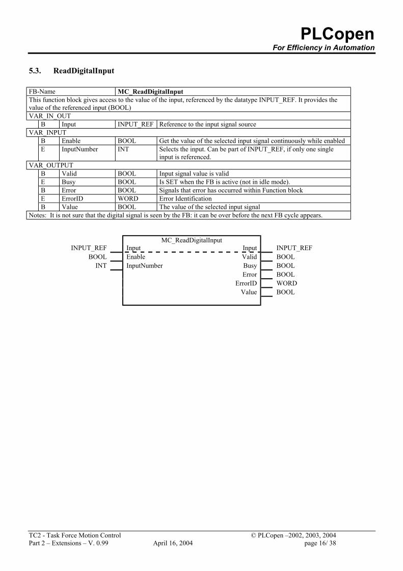
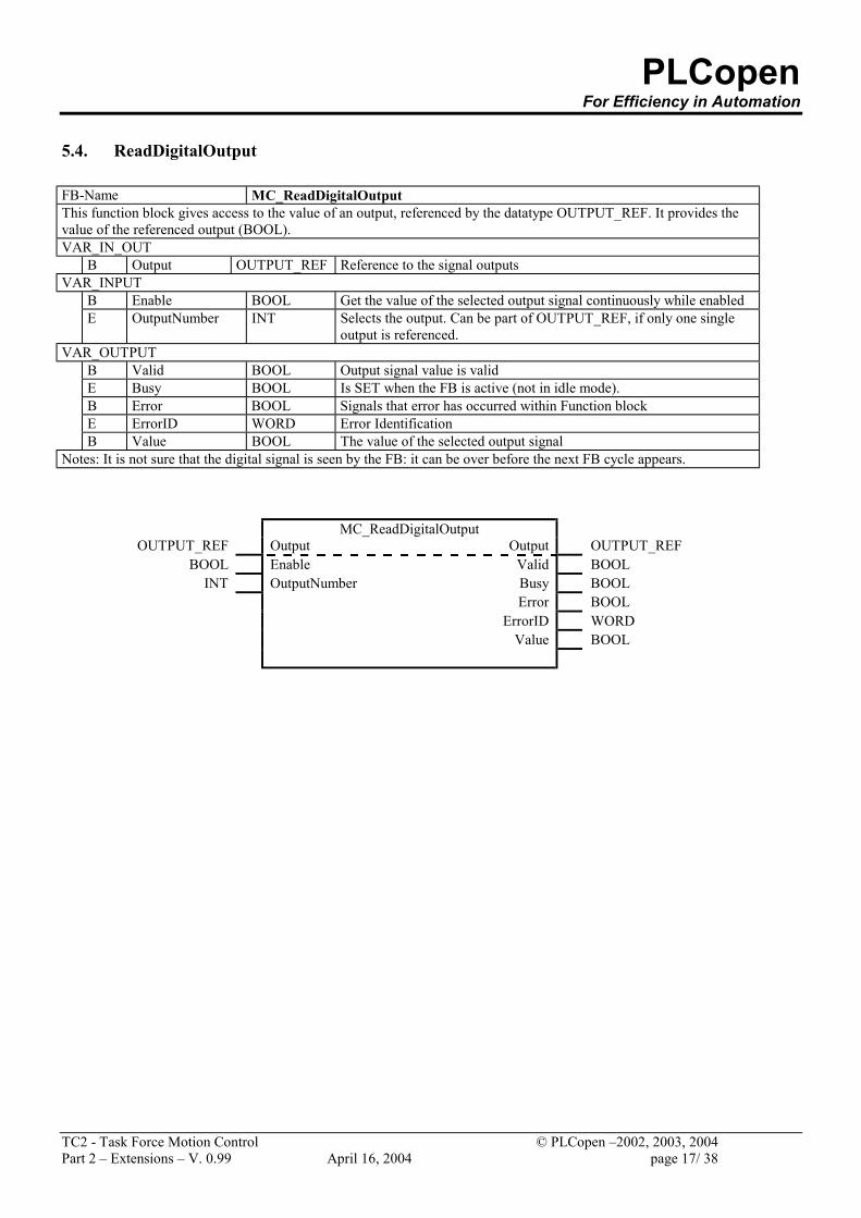
5.3. ReadDigitalInput FB-Name MC_ReadDigitalInput This function block gives access to the value of the input, referenced by the datatype INPUT_REF. It provides the value of the referenced input (BOOL) VAR_IN_OUT
B Input INPUT_REF Reference to the input signal source VAR_INPUT
B Enable BOOL Get the value of the selected input signal continuously while enabled E InputNumber INT Selects the input. Can be part of INPUT_REF, if only one single
input is referenced. VAR_OUTPUT
B Valid BOOL Input signal value is valid E Busy BOOL Is SET when the FB is active (not in idle mode). B Error BOOL Signals that error has occurred within Function block E ErrorID WORD Error Identification B Value BOOL The value of the selected input signal
Notes: It is not sure that the digital signal is seen by the FB: it can be over before the next FB cycle appears.
MC_ReadDigitalInput INPUT_REF Input Input INPUT_REF
BOOL Enable Valid BOOL INT InputNumber Busy BOOL
Error BOOL ErrorID WORD Value BOOL
PLCopen For Efficiency in Automation
TC2 - Task Force Motion Control © PLCopen –2002, 2003, 2004 Part 2 – Extensions – V. 0.99 April 16, 2004 page 17/ 38
5.4. ReadDigitalOutput FB-Name MC_ReadDigitalOutput This function block gives access to the value of an output, referenced by the datatype OUTPUT_REF. It provides the value of the referenced output (BOOL). VAR_IN_OUT
B Output OUTPUT_REF Reference to the signal outputs VAR_INPUT
B Enable BOOL Get the value of the selected output signal continuously while enabled E OutputNumber INT Selects the output. Can be part of OUTPUT_REF, if only one single
output is referenced. VAR_OUTPUT
B Valid BOOL Output signal value is valid E Busy BOOL Is SET when the FB is active (not in idle mode). B Error BOOL Signals that error has occurred within Function block E ErrorID WORD Error Identification B Value BOOL The value of the selected output signal
Notes: It is not sure that the digital signal is seen by the FB: it can be over before the next FB cycle appears.
MC_ReadDigitalOutput OUTPUT_REF Output Output OUTPUT_REF
BOOL Enable Valid BOOL INT OutputNumber Busy BOOL
Error BOOL ErrorID WORD Value BOOL
PLCopen For Efficiency in Automation
TC2 - Task Force Motion Control © PLCopen –2002, 2003, 2004 Part 2 – Extensions – V. 0.99 April 16, 2004 page 18/ 38
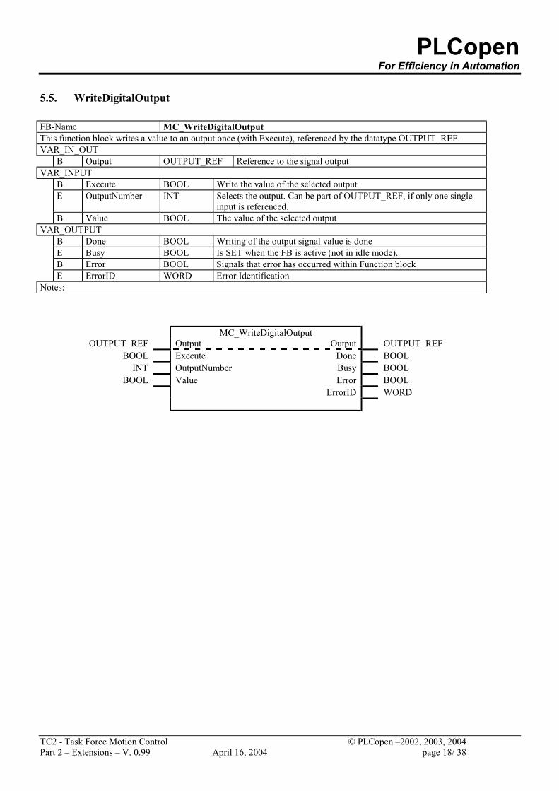
5.5. WriteDigitalOutput FB-Name MC_WriteDigitalOutput This function block writes a value to an output once (with Execute), referenced by the datatype OUTPUT_REF. VAR_IN_OUT
B Output OUTPUT_REF Reference to the signal output VAR_INPUT
B Execute BOOL Write the value of the selected output E OutputNumber INT Selects the output. Can be part of OUTPUT_REF, if only one single
input is referenced. B Value BOOL The value of the selected output
VAR_OUTPUT B Done BOOL Writing of the output signal value is done E Busy BOOL Is SET when the FB is active (not in idle mode). B Error BOOL Signals that error has occurred within Function block E ErrorID WORD Error Identification
Notes:
MC_WriteDigitalOutput OUTPUT_REF Output Output OUTPUT_REF
BOOL Execute Done BOOL INT OutputNumber Busy BOOL
BOOL Value Error BOOL ErrorID WORD
PLCopen For Efficiency in Automation
TC2 - Task Force Motion Control © PLCopen –2002, 2003, 2004 Part 2 – Extensions – V. 0.99 April 16, 2004 page 19/ 38
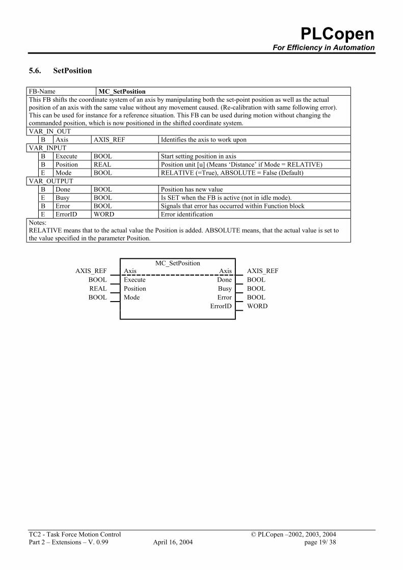
5.6. SetPosition FB-Name MC_SetPosition This FB shifts the coordinate system of an axis by manipulating both the set-point position as well as the actual position of an axis with the same value without any movement caused. (Re-calibration with same following error). This can be used for instance for a reference situation. This FB can be used during motion without changing the commanded position, which is now positioned in the shifted coordinate system. VAR_IN_OUT
B Axis AXIS_REF Identifies the axis to work upon VAR_INPUT
B Execute BOOL Start setting position in axis B Position REAL Position unit [u] (Means ‘Distance’ if Mode = RELATIVE) E Mode BOOL RELATIVE (=True), ABSOLUTE = False (Default)
VAR_OUTPUT B Done BOOL Position has new value E Busy BOOL Is SET when the FB is active (not in idle mode). B Error BOOL Signals that error has occurred within Function block E ErrorID WORD Error identification
Notes: RELATIVE means that to the actual value the Position is added. ABSOLUTE means, that the actual value is set to the value specified in the parameter Position.
MC_SetPosition AXIS_REF Axis Axis AXIS_REF
BOOL Execute Done BOOL REAL Position Busy BOOL BOOL Mode Error BOOL
ErrorID WORD
PLCopen For Efficiency in Automation
TC2 - Task Force Motion Control © PLCopen –2002, 2003, 2004 Part 2 – Extensions – V. 0.99 April 16, 2004 page 20/ 38
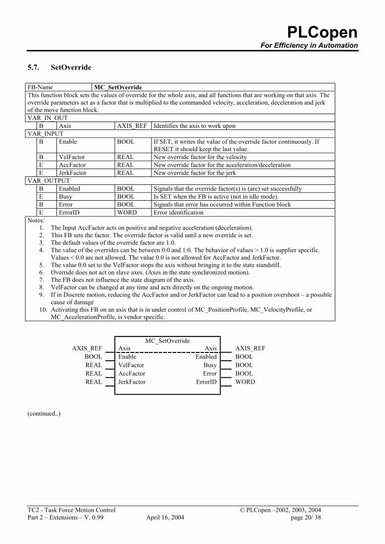
5.7. SetOverride FB-Name MC_SetOverride This function block sets the values of override for the whole axis, and all functions that are working on that axis. The override parameters act as a factor that is multiplied to the commanded velocity, acceleration, deceleration and jerk of the move function block. VAR_IN_OUT
B Axis AXIS_REF Identifies the axis to work upon VAR_INPUT
B Enable BOOL If SET, it writes the value of the override factor continuously. If RESET it should keep the last value.
B VelFactor REAL New override factor for the velocity E AccFactor REAL New override factor for the acceleration/deceleration E JerkFactor REAL New override factor for the jerk
VAR_OUTPUT B Enabled BOOL Signals that the override factor(s) is (are) set successfully E Busy BOOL Is SET when the FB is active (not in idle mode). B Error BOOL Signals that error has occurred within Function block E ErrorID WORD Error identification
Notes: 1. The Input AccFactor acts on positive and negative acceleration (deceleration). 2. This FB sets the factor. The override factor is valid until a new override is set. 3. The default values of the override factor are 1.0. 4. The value of the overrides can be between 0.0 and 1.0. The behavior of values > 1.0 is supplier specific.
Values < 0.0 are not allowed. The value 0.0 is not allowed for AccFactor and JerkFactor. 5. The value 0.0 set to the VelFactor stops the axis without bringing it to the state standstill. 6. Override does not act on slave axes. (Axes in the state synchronized motion). 7. The FB does not influence the state diagram of the axis. 8. VelFactor can be changed at any time and acts directly on the ongoing motion. 9. If in Discrete motion, reducing the AccFactor and/or JerkFactor can lead to a position overshoot – a possible
cause of damage 10. Activating this FB on an axis that is in under control of MC_PositionProfile, MC_VelocityProfile, or
MC_AccelerationProfile, is vendor specific.
MC_SetOverride AXIS_REF Axis Axis AXIS_REF
BOOL Enable Enabled BOOL REAL VelFactor Busy BOOL REAL AccFactor Error BOOL REAL JerkFactor ErrorID WORD
(continued..)
PLCopen For Efficiency in Automation
TC2 - Task Force Motion Control © PLCopen –2002, 2003, 2004 Part 2 – Extensions – V. 0.99 April 16, 2004 page 21/ 38
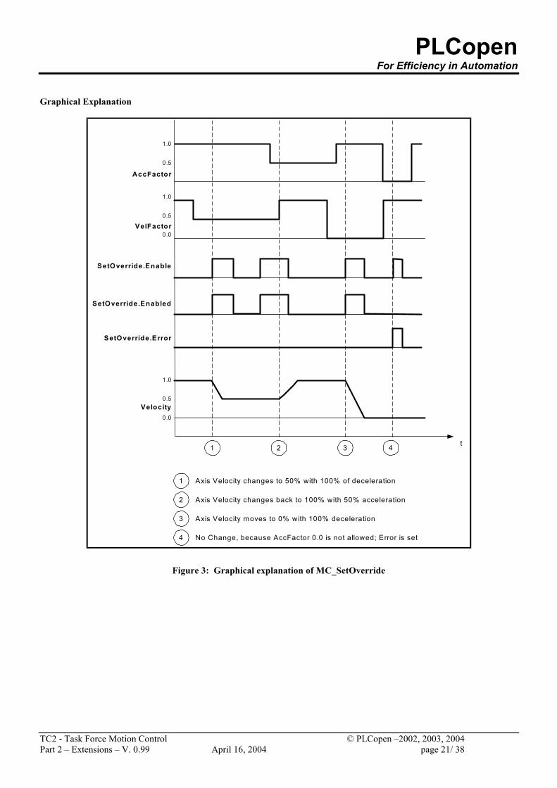
Graphical Explanation
SetOverride.Enable
SetOverride.Enabled
SetOverride.Error
t
Velocity
AccFactor
1.0
0.5
VelFactor
1.0
0.5
1 2 3
1
2
3
Axis Velocity changes to 50% with 100% of deceleration
Axis Velocity changes back to 100% with 50% acceleration
Axis Velocity moves to 0% with 100% deceleration
1.0
0.5
0.0
0.0
4
4 No Change, because AccFactor 0.0 is not allowed; Error is set
Figure 3: Graphical explanation of MC_SetOverride
PLCopen For Efficiency in Automation
TC2 - Task Force Motion Control © PLCopen –2002, 2003, 2004 Part 2 – Extensions – V. 0.99 April 16, 2004 page 22/ 38
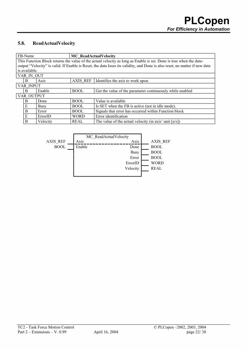
5.8. ReadActualVelocity FB-Name MC_ReadActualVelocity This Function Block returns the value of the actual velocity as long as Enable is set. Done is true when the data-output “Velocity” is valid. If Enable is Reset, the data loses its validity, and Done is also reset, no matter if new data is available. VAR_IN_OUT
B Axis AXIS_REF Identifies the axis to work upon VAR_INPUT
B Enable BOOL Get the value of the parameter continuously while enabled VAR_OUTPUT
B Done BOOL Value is available E Busy BOOL Is SET when the FB is active (not in idle mode). B Error BOOL Signals that error has occurred within Function block E ErrorID WORD Error identification B Velocity REAL The value of the actual velocity (in axis’ unit [u/s])
MC_ReadActualVelocity AXIS_REF Axis Axis AXIS_REF
BOOL Enable Done BOOL Busy BOOL Error BOOL ErrorID WORD Velocity REAL
PLCopen For Efficiency in Automation
TC2 - Task Force Motion Control © PLCopen –2002, 2003, 2004 Part 2 – Extensions – V. 0.99 April 16, 2004 page 23/ 38
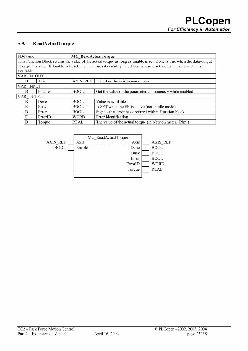
5.9. ReadActualTorque FB-Name MC_ReadActualTorque This Function Block returns the value of the actual torque as long as Enable is set. Done is true when the data-output “Torque” is valid. If Enable is Reset, the data loses its validity, and Done is also reset, no matter if new data is available. VAR_IN_OUT
B Axis AXIS_REF Identifies the axis to work upon VAR_INPUT
B Enable BOOL Get the value of the parameter continuously while enabled VAR_OUTPUT
B Done BOOL Value is available E Busy BOOL Is SET when the FB is active (not in idle mode). B Error BOOL Signals that error has occurred within Function block E ErrorID WORD Error identification B Torque REAL The value of the actual torque (in Newton meters [Nm])
MC_ReadActualTorque AXIS_REF Axis Axis AXIS_REF
BOOL Enable Done BOOL Busy BOOL Error BOOL ErrorID WORD Torque REAL
PLCopen For Efficiency in Automation
TC2 - Task Force Motion Control © PLCopen –2002, 2003, 2004 Part 2 – Extensions – V. 0.99 April 16, 2004 page 24/ 38
5.10. TorqueControl
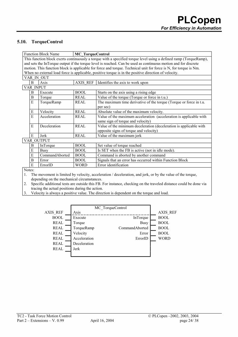
Function Block Name MC_TorqueControl This function block exerts continuously a torque with a specified torque level using a defined ramp (TorqueRamp), and sets the InTorque output if the torque level is reached. Can be used as continuous motion and for discrete motion. This function block is applicable for force and torque. Technical unit for force is N, for torque is Nm. When no external load force is applicable, positive torque is in the positive direction of velocity. VAR_IN_OUT
B Axis AXIS_REF Identifies the axis to work upon VAR_INPUT
B Execute BOOL Starts on the axis using a rising edge B Torque REAL Value of the torque (Torque or force in t.u.) E TorqueRamp REAL The maximum time derivative of the torque (Torque or force in t.u.
per sec) E Velocity REAL Absolute value of the maximum velocity. E Acceleration REAL Value of the maximum acceleration (acceleration is applicable with
same sign of torque and velocity) E Deceleration REAL Value of the minimum deceleration (deceleration is applicable with
opposite signs of torque and velocity) E Jerk REAL Value of the maximum jerk
VAR_OUTPUT B InTorque BOOL Set value of torque reached E Busy BOOL Is SET when the FB is active (not in idle mode). E CommandAborted BOOL Command is aborted by another command B Error BOOL Signals that an error has occurred within Function Block E ErrorID WORD Error identification
Notes: 1. The movement is limited by velocity, acceleration / deceleration, and jerk, or by the value of the torque,
depending on the mechanical circumstances. 2. Specific additional tests are outside this FB. For instance, checking on the traveled distance could be done via
tracing the actual positions during the action. 3. Velocity is always a positive value. The direction is dependent on the torque and load.
MC_TorqueControl AXIS_REF Axis AXIS_REF
BOOL Execute InTorque BOOL REAL Torque Busy BOOL REAL TorqueRamp CommandAborted BOOL REAL Velocity Error BOOL REAL Acceleration ErrorID WORD REAL Deceleration REAL Jerk
PLCopen For Efficiency in Automation
TC2 - Task Force Motion Control © PLCopen –2002, 2003, 2004 Part 2 – Extensions – V. 0.99 April 16, 2004 page 25/ 38
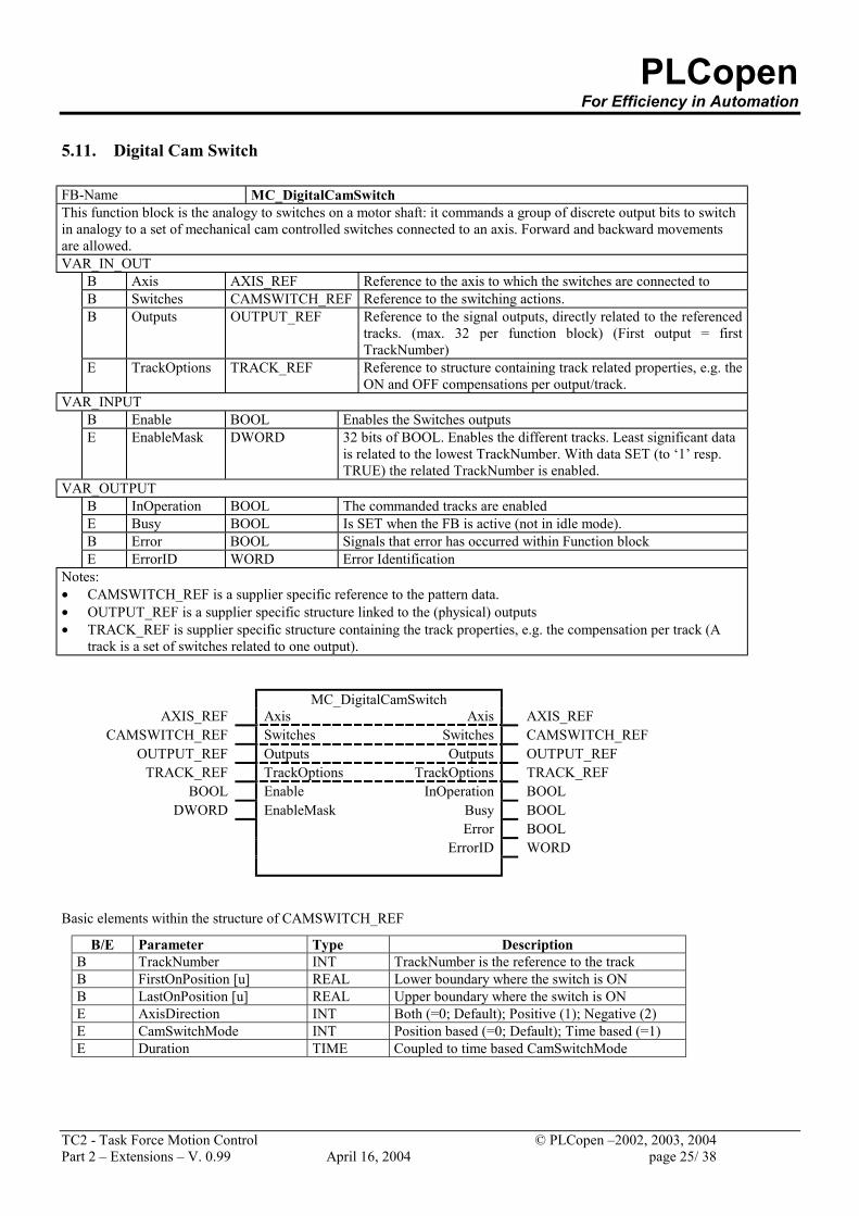
5.11. Digital Cam Switch FB-Name MC_DigitalCamSwitch This function block is the analogy to switches on a motor shaft: it commands a group of discrete output bits to switch in analogy to a set of mechanical cam controlled switches connected to an axis. Forward and backward movements are allowed. VAR_IN_OUT
B Axis AXIS_REF Reference to the axis to which the switches are connected to B Switches CAMSWITCH_REF Reference to the switching actions. B Outputs OUTPUT_REF Reference to the signal outputs, directly related to the referenced
tracks. (max. 32 per function block) (First output = first TrackNumber)
E TrackOptions TRACK_REF Reference to structure containing track related properties, e.g. the ON and OFF compensations per output/track.
VAR_INPUT B Enable BOOL Enables the Switches outputs E EnableMask DWORD 32 bits of BOOL. Enables the different tracks. Least significant data
is related to the lowest TrackNumber. With data SET (to ‘1’ resp. TRUE) the related TrackNumber is enabled.
VAR_OUTPUT B InOperation BOOL The commanded tracks are enabled E Busy BOOL Is SET when the FB is active (not in idle mode). B Error BOOL Signals that error has occurred within Function block E ErrorID WORD Error Identification
Notes: • CAMSWITCH_REF is a supplier specific reference to the pattern data. • OUTPUT_REF is a supplier specific structure linked to the (physical) outputs • TRACK_REF is supplier specific structure containing the track properties, e.g. the compensation per track (A
track is a set of switches related to one output).
MC_DigitalCamSwitch AXIS_REF Axis Axis AXIS_REF
CAMSWITCH_REF Switches Switches CAMSWITCH_REF OUTPUT_REF Outputs Outputs OUTPUT_REF
TRACK_REF TrackOptions TrackOptions TRACK_REF BOOL Enable InOperation BOOL
DWORD EnableMask Busy BOOL Error BOOL ErrorID WORD
Basic elements within the structure of CAMSWITCH_REF
B/E Parameter Type Description B TrackNumber INT TrackNumber is the reference to the track B FirstOnPosition [u] REAL Lower boundary where the switch is ON B LastOnPosition [u] REAL Upper boundary where the switch is ON E AxisDirection INT Both (=0; Default); Positive (1); Negative (2) E CamSwitchMode INT Position based (=0; Default); Time based (=1) E Duration TIME Coupled to time based CamSwitchMode
PLCopen For Efficiency in Automation
TC2 - Task Force Motion Control © PLCopen –2002, 2003, 2004 Part 2 – Extensions – V. 0.99 April 16, 2004 page 26/ 38
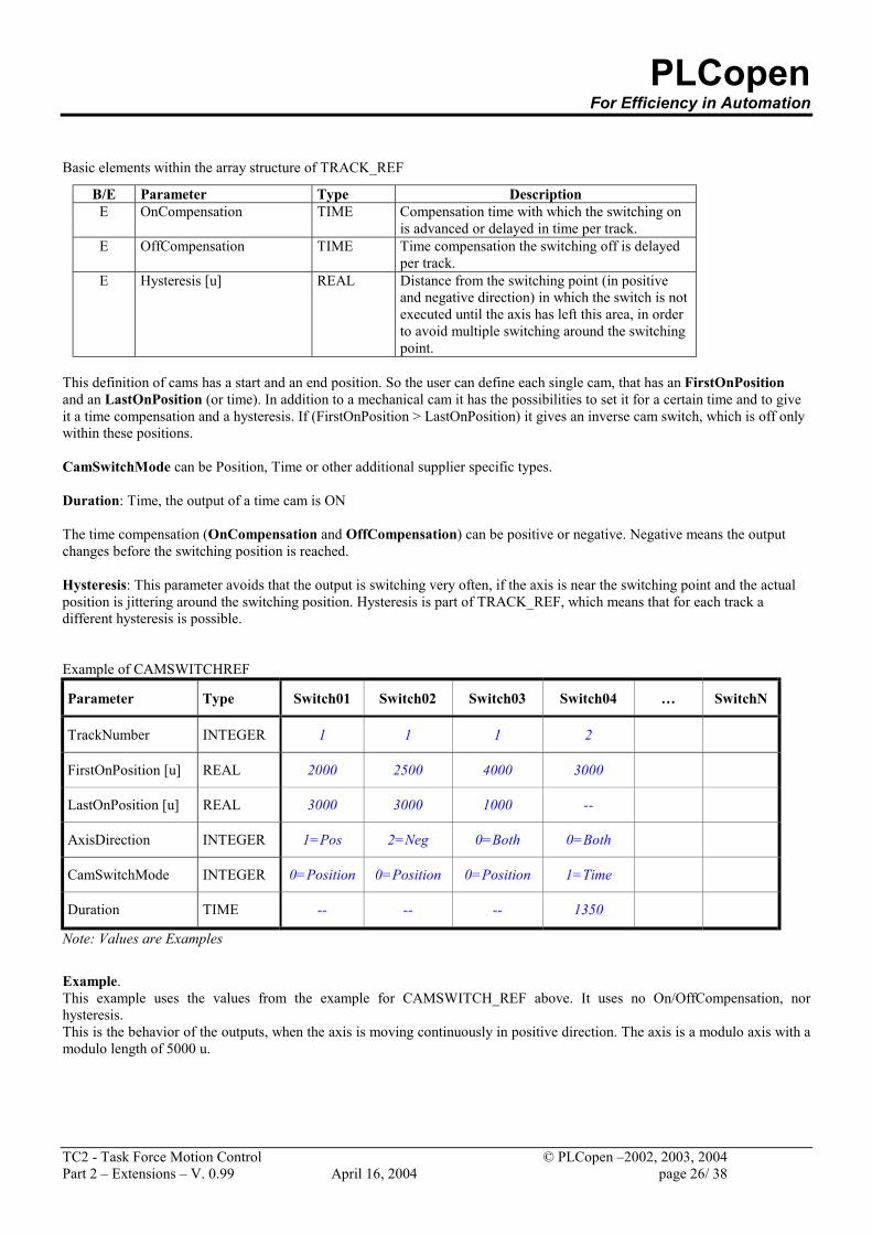
Basic elements within the array structure of TRACK_REF
B/E Parameter Type Description E OnCompensation TIME Compensation time with which the switching on
is advanced or delayed in time per track. E OffCompensation TIME Time compensation the switching off is delayed
per track. E Hysteresis [u] REAL Distance from the switching point (in positive
and negative direction) in which the switch is not executed until the axis has left this area, in order to avoid multiple switching around the switching point.
This definition of cams has a start and an end position. So the user can define each single cam, that has an FirstOnPosition and an LastOnPosition (or time). In addition to a mechanical cam it has the possibilities to set it for a certain time and to give it a time compensation and a hysteresis. If (FirstOnPosition > LastOnPosition) it gives an inverse cam switch, which is off only within these positions. CamSwitchMode can be Position, Time or other additional supplier specific types. Duration: Time, the output of a time cam is ON The time compensation (OnCompensation and OffCompensation) can be positive or negative. Negative means the output changes before the switching position is reached. Hysteresis: This parameter avoids that the output is switching very often, if the axis is near the switching point and the actual position is jittering around the switching position. Hysteresis is part of TRACK_REF, which means that for each track a different hysteresis is possible. Example of CAMSWITCHREF
Parameter Type Switch01 Switch02 Switch03 Switch04 … SwitchN
TrackNumber INTEGER 1 1 1 2
FirstOnPosition [u] REAL 2000 2500 4000 3000
LastOnPosition [u] REAL 3000 3000 1000 --
AxisDirection INTEGER 1=Pos 2=Neg 0=Both 0=Both
CamSwitchMode INTEGER 0=Position 0=Position 0=Position 1=Time
Duration TIME -- -- -- 1350
Note: Values are Examples
Example. This example uses the values from the example for CAMSWITCH_REF above. It uses no On/OffCompensation, nor hysteresis. This is the behavior of the outputs, when the axis is moving continuously in positive direction. The axis is a modulo axis with a modulo length of 5000 u.
PLCopen For Efficiency in Automation
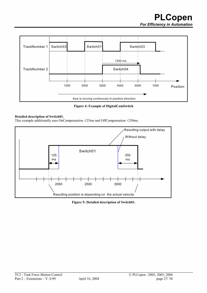
TC2 - Task Force Motion Control © PLCopen –2002, 2003, 2004 Part 2 – Extensions – V. 0.99 April 16, 2004 page 27/ 38
Position
TrackNumber 1
1000 2000 3000 4000 5000 1000
TrackNumber 2
Switch03 Switch01 Switch03
1350 ms
Switch04
Axis is moving continously in positive direction Figure 4: Example of DigitalCamSwitch
Detailed description of Switch01. This example additionally uses OnCompensation -125ms and OffCompensation +250ms.
2000 3000
125ms
250ms
Switch01
Without delay
Resulting output with delay
2500
Resulting position is depending on the actual velocity Figure 5: Detailed description of Switch01.
PLCopen For Efficiency in Automation
TC2 - Task Force Motion Control © PLCopen –2002, 2003, 2004 Part 2 – Extensions – V. 0.99 April 16, 2004 page 28/ 38
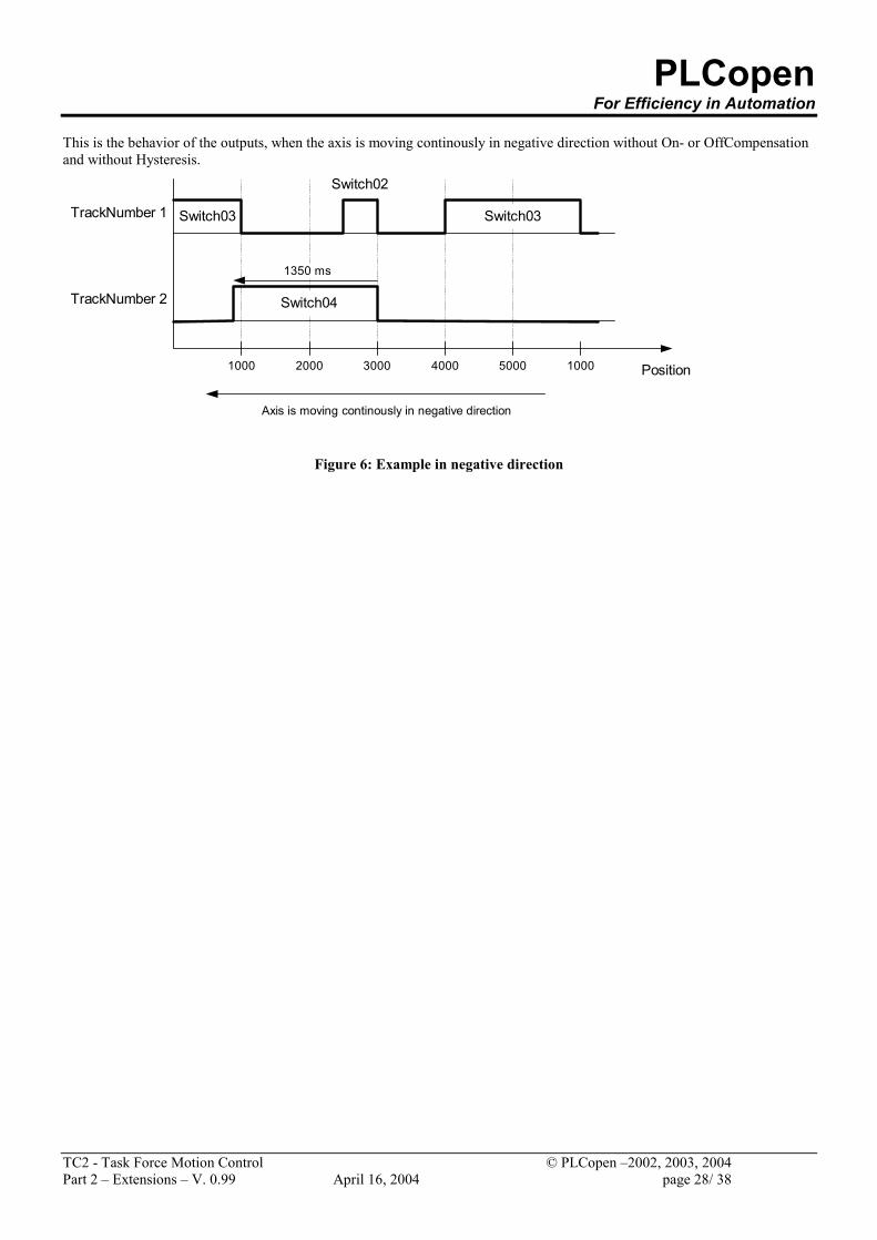
This is the behavior of the outputs, when the axis is moving continously in negative direction without On- or OffCompensation and without Hysteresis.
Switch03
Position
TrackNumber 1
1000 2000 3000 4000 5000 1000
TrackNumber 2
Switch02
Switch03
1350 ms
Switch04
Axis is moving continously in negative direction
Figure 6: Example in negative direction
PLCopen For Efficiency in Automation
TC2 - Task Force Motion Control © PLCopen –2002, 2003, 2004 Part 2 – Extensions – V. 0.99 April 16, 2004 page 29/ 38
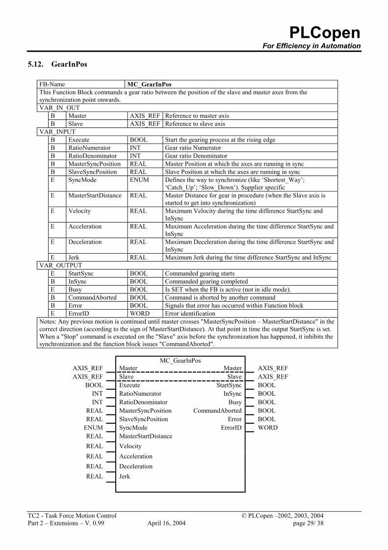
5.12. GearInPos
FB-Name MC_GearInPos This Function Block commands a gear ratio between the position of the slave and master axes from the synchronization point onwards. VAR_IN_OUT
B Master AXIS_REF Reference to master axis B Slave AXIS_REF Reference to slave axis
VAR_INPUT B Execute BOOL Start the gearing process at the rising edge B RatioNumerator INT Gear ratio Numerator B RatioDenominator INT Gear ratio Denominator B MasterSyncPosition REAL Master Position at which the axes are running in sync B SlaveSyncPosition REAL Slave Position at which the axes are running in sync E SyncMode ENUM Defines the way to synchronize (like ‘Shortest_Way’;
‘Catch_Up’; ‘Slow_Down’). Supplier specific E MasterStartDistance REAL Master Distance for gear in procedure (when the Slave axis is
started to get into synchronization) E Velocity REAL Maximum Velocity during the time difference StartSync and
InSync E Acceleration REAL Maximum Acceleration during the time difference StartSync and
InSync E Deceleration REAL Maximum Deceleration during the time difference StartSync and
InSync E Jerk REAL Maximum Jerk during the time difference StartSync and InSync
VAR_OUTPUT E StartSync BOOL Commanded gearing starts B InSync BOOL Commanded gearing completed E Busy BOOL Is SET when the FB is active (not in idle mode). B CommandAborted BOOL Command is aborted by another command B Error BOOL Signals that error has occurred within Function block E ErrorID WORD Error identification
Notes: Any previous motion is continued until master crosses "MasterSyncPosition – MasterStartDistance" in the correct direction (according to the sign of MasterStartDistance). At that point in time the output StartSync is set. When a "Stop" command is executed on the "Slave" axis before the synchronization has happened, it inhibits the synchronization and the function block issues "CommandAborted".
MC_GearInPos
AXIS_REF Master Master AXIS_REF AXIS_REF Slave Slave AXIS_REF
BOOL Execute StartSync BOOL INT RatioNumerator InSync BOOL INT RatioDenominator Busy BOOL
REAL MasterSyncPosition CommandAborted BOOL REAL SlaveSyncPosition Error BOOL
ENUM SyncMode ErrorID WORD REAL MasterStartDistance REAL Velocity REAL Acceleration REAL Deceleration REAL Jerk
PLCopen For Efficiency in Automation
TC2 - Task Force Motion Control © PLCopen –2002, 2003, 2004 Part 2 – Extensions – V. 0.99 April 16, 2004 page 30/ 38
InSyncFALSE
TRUE
Execute
FALSE
TRUE
FALSE
TRUE
MasterSyncPosition
SlaveSyncPosition
t
t
t
t
t
StartSync
MasterStartDistance
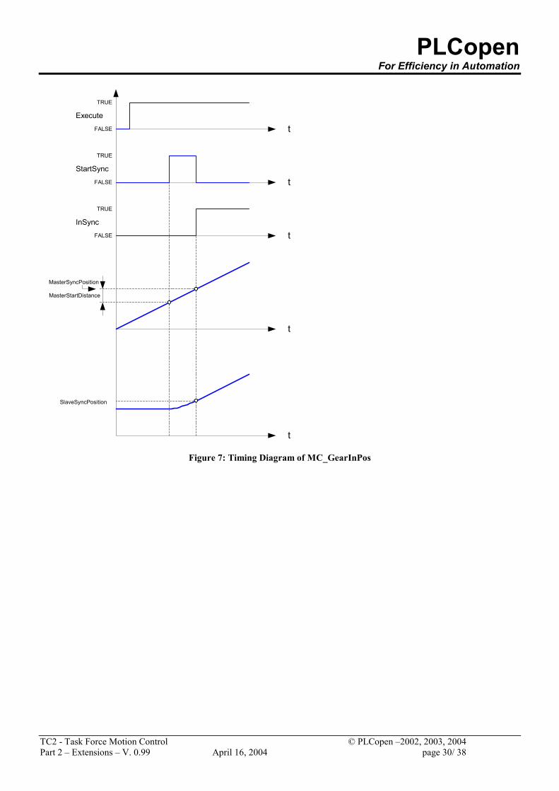
Figure 7: Timing Diagram of MC_GearInPos
PLCopen For Efficiency in Automation
TC2 - Task Force Motion Control © PLCopen –2002, 2003, 2004 Part 2 – Extensions – V. 0.99 April 16, 2004 page 31/ 38
MasterSyncPosition
SlaveSyncPosition
MasterStartDistance
Master Position
Slave Position GearInPos
MasterSyncPosition
SlaveSyncPosition
MasterStartDistance
Master Position
Slave Position GearInPos
Pic1
Pic2
MasterSyncPosition
SlaveSyncPosition
MasterStartDistance Master Position
Slave Position GearInPos
Pic3
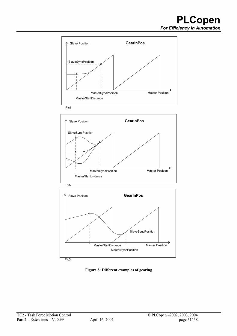
Figure 8: Different examples of gearing
PLCopen For Efficiency in Automation
TC2 - Task Force Motion Control © PLCopen –2002, 2003, 2004 Part 2 – Extensions – V. 0.99 April 16, 2004 page 32/ 38
6. Appendix A – Compliance Statement Listed in this Appendix are the requirements for the compliance statement from the supplier of the Motion Control Function Blocks. This part should be seen as integral to Part 1 – Function Blocks for Motion Control. The compliance statement consists of two main groups: supported datatypes and supported Function Blocks, in combination with the applicable inputs and outputs. The supplier has to fill out the tables for the used datatypes and Function Blocks, according to their product, committing their support to the specification. By submitting these tables to PLCopen, as well as those from Part 1, and after approval by PLCopen, the list will be published on the PLCopen website, www.plcopen.org , as well as a short form overview, as specified in Appendix A 2 Supported Datatypes and Appendix A 3 Overview of the Function Blocks here below. In addition to this approval, the supplier gets access and usage rights of the PLCopen Motion Control logo, as described in Part 1, chapter Appendix A 4 The PLCopen Motion Control Logo and Its Usage.
PLCopen For Efficiency in Automation
TC2 - Task Force Motion Control © PLCopen –2002, 2003, 2004 Part 2 – Extensions – V. 0.99 April 16, 2004 page 33/ 38
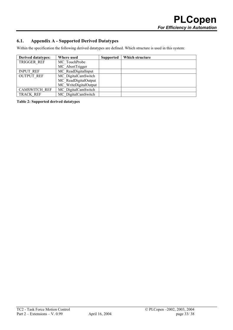
6.1. Appendix A - Supported Derived Datatypes Within the specification the following derived datatypes are defined. Which structure is used in this system:
Derived datatypes: Where used Supported Which structure TRIGGER_REF MC_TouchProbe
MC_AbortTrigger
INPUT_REF MC_ReadDigitalInput OUTPUT_REF MC_DigitalCamSwitch
MC_ReadDigitalOutput MC_WriteDigitalOutput
CAMSWITCH_REF MC_DigitalCamSwitch TRACK_REF MC_DigitalCamSwitch
Table 2: Supported derived datatypes
PLCopen For Efficiency in Automation
TC2 - Task Force Motion Control © PLCopen –2002, 2003, 2004 Part 2 – Extensions – V. 0.99 April 16, 2004 page 34/ 38
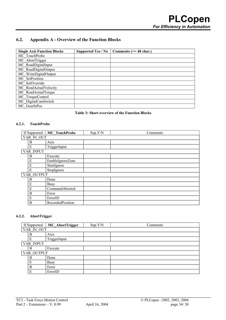
6.2. Appendix A - Overview of the Function Blocks
Single Axis Function Blocks Supported Yes / No Comments (<= 48 char.) MC_TouchProbe MC_AbortTrigger MC_ReadDigitalInput MC_ReadDigitalOutput MC_WriteDigitalOutput MC_SetPosition MC_SetOverride MC_ReadActualVelocity MC_ReadActualTorque MC_TorqueControl MC_DigitalCamSwitch MC_GearInPos
Table 3: Short overview of the Function Blocks
6.2.1. TouchProbe
If Supported MC_TouchProbe Sup.Y/N Comments VAR_IN_OUT
B Axis E TriggerInput
VAR_INPUT B Execute E EnableIgnoreZone E StartIgnore E StopIgnore
VAR_OUTPUT B Done E Busy E CommandAborted B Error E ErrorID B RecordedPosition
6.2.2. AbortTrigger
If Supported MC_AbortTrigger Sup.Y/N Comments VAR_IN_OUT
B Axis E TriggerInput
VAR_INPUT B Execute
VAR_OUTPUT B Done E Busy B Error E ErrorID
PLCopen For Efficiency in Automation
TC2 - Task Force Motion Control © PLCopen –2002, 2003, 2004 Part 2 – Extensions – V. 0.99 April 16, 2004 page 35/ 38
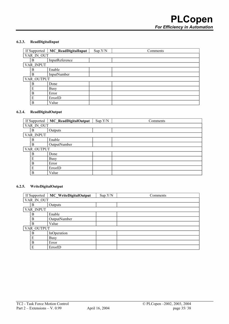
6.2.3. ReadDigitalInput
If Supported MC_ReadDigitalInput Sup.Y/N Comments VAR_IN_OUT
B InputReference VAR_INPUT
B Enable B InputNumber
VAR_OUTPUT B Done E Busy B Error E ErrorID B Value
6.2.4. ReadDigitalOutput
If Supported MC_ReadDigitalOutput Sup.Y/N Comments VAR_IN_OUT
B Outputs VAR_INPUT
B Enable B OutputNumber
VAR_OUTPUT B Done E Busy B Error E ErrorID B Value
6.2.5. WriteDigitalOutput
If Supported MC_WriteDigitalOutput Sup.Y/N Comments VAR_IN_OUT
B Outputs VAR_INPUT
B Enable B OutputNumber B Value
VAR_OUTPUT B InOperation E Busy B Error E ErrorID
PLCopen For Efficiency in Automation
TC2 - Task Force Motion Control © PLCopen –2002, 2003, 2004 Part 2 – Extensions – V. 0.99 April 16, 2004 page 36/ 38
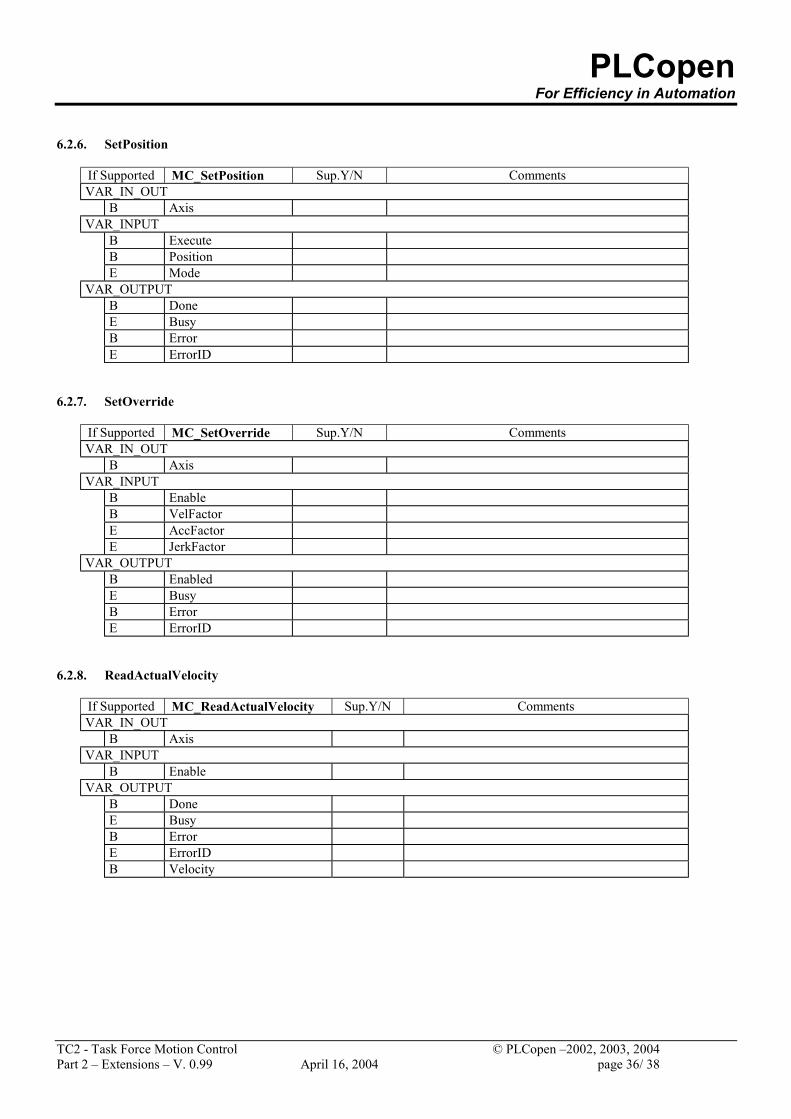
6.2.6. SetPosition
If Supported MC_SetPosition Sup.Y/N Comments VAR_IN_OUT
B Axis VAR_INPUT
B Execute B Position E Mode
VAR_OUTPUT B Done E Busy B Error E ErrorID
6.2.7. SetOverride
If Supported MC_SetOverride Sup.Y/N Comments VAR_IN_OUT
B Axis VAR_INPUT
B Enable B VelFactor E AccFactor E JerkFactor
VAR_OUTPUT B Enabled E Busy B Error E ErrorID
6.2.8. ReadActualVelocity
If Supported MC_ReadActualVelocity Sup.Y/N Comments VAR_IN_OUT
B Axis VAR_INPUT
B Enable VAR_OUTPUT
B Done E Busy B Error E ErrorID B Velocity
PLCopen For Efficiency in Automation
TC2 - Task Force Motion Control © PLCopen –2002, 2003, 2004 Part 2 – Extensions – V. 0.99 April 16, 2004 page 37/ 38
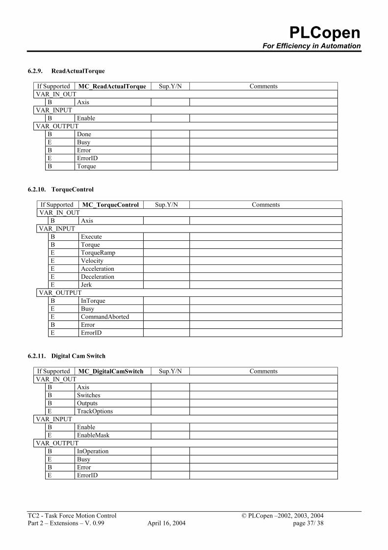
6.2.9. ReadActualTorque
If Supported MC_ReadActualTorque Sup.Y/N Comments VAR_IN_OUT
B Axis VAR_INPUT
B Enable VAR_OUTPUT
B Done E Busy B Error E ErrorID B Torque
6.2.10. TorqueControl
If Supported MC_TorqueControl Sup.Y/N Comments VAR_IN_OUT
B Axis VAR_INPUT
B Execute B Torque E TorqueRamp E Velocity E Acceleration E Deceleration E Jerk
VAR_OUTPUT B InTorque E Busy E CommandAborted B Error E ErrorID
6.2.11. Digital Cam Switch
If Supported MC_DigitalCamSwitch Sup.Y/N Comments VAR_IN_OUT
B Axis B Switches B Outputs E TrackOptions
VAR_INPUT B Enable E EnableMask
VAR_OUTPUT B InOperation E Busy B Error E ErrorID
PLCopen For Efficiency in Automation
TC2 - Task Force Motion Control © PLCopen –2002, 2003, 2004 Part 2 – Extensions – V. 0.99 April 16, 2004 page 38/ 38
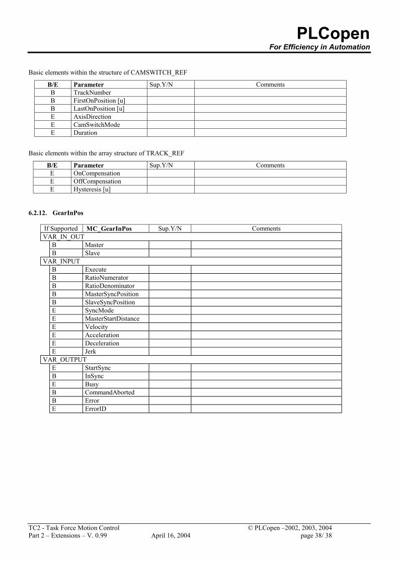
Basic elements within the structure of CAMSWITCH_REF
B/E Parameter Sup.Y/N Comments B TrackNumber B FirstOnPosition [u] B LastOnPosition [u] E AxisDirection E CamSwitchMode E Duration
Basic elements within the array structure of TRACK_REF
B/E Parameter Sup.Y/N Comments E OnCompensation E OffCompensation E Hysteresis [u]
6.2.12. GearInPos
If Supported MC_GearInPos Sup.Y/N Comments VAR_IN_OUT
B Master B Slave
VAR_INPUT B Execute B RatioNumerator B RatioDenominator B MasterSyncPosition B SlaveSyncPosition E SyncMode E MasterStartDistance E Velocity E Acceleration E Deceleration E Jerk
VAR_OUTPUT E StartSync B InSync E Busy B CommandAborted B Error E ErrorID
Recommended