Embed Size (px)
Citation preview
RC-HELI AND STRUCTURE & MOTION TECHNIQUES FOR THE 3-D
RECONSTRUCTION OF A MILAN DOME SPIRE
M. Scaioni, L. Barazzetti, R. Brumana, B. Cuca, F. Fassi, F. Prandi
Politecnico di Milano, Dept. BEST/SITE Group, piazza L. da Vinci 32, 20133 Milano, Italy
e-mail: {marco.scaioni; luigi.barazzetti; raffaella.brumana; branka.cuca; francesco.fassi; federico.prandi}@polimi.it
KEY WORDS: Cultural Heritage, 3-D Reconstruction, Structure and Motion, UAV
ABSTRACT:
The paper describes a complete workflow for the 3-D photogrammetric surveying and modeling of complex architectonical objects.
The application is focused to the major spire of the Dome of Milan, that is characterized by the well known striking vertical
geometry and a high level of complexity. Because no positions from which capturing images and scans exists, a 5 kg payload model
helicopter has been used to lift and carry a calibrated digital camera, which has been adopted to capture images for the reconstruction
of highest part of the spire. The huge quantity of image data has been partially oriented with a new algorithm able to detect
automatically corresponding tie points among the overlapping images by using a Structure & Motion approach, but extended to
blocks with a generic shape. The algorithm can identify homologous points with the SIFT operator alternated to a robust estimation
of camera poses to remove wrong correspondences. Then a progressive resection alternated with triangulation is carried out to
determine the orientation parameters of each image. Finally a photogrammetric bundle adjustment is computed to derive final
exterior orientation parameters.
1. INTRODUCTION
1.1 UAV: a new paradigm for photogrammetry
In the latest five years one of the most emerging technology in
photogrammetry is undoubtedly represented by unmanned
aerial vehicles or UAVs (van Blyenburg, 1999). The interest for
these flying platforms in motivated by several grounds related to
several fields of possible application. In aerial survey, they
allow a high resolution image acquisition, because of the
possibility to fly at very low height on the ground with respect
to manned aircraft and helicopters. The possibility of mounting
sensors in tilted position can be exploited for imaging some
kinds of objects which are difficult to capture in standard aerial
imagery. Typical examples of this are building façades,
waterfronts or vertical rock faces (Eisenbeiss, 2008). So far,
digital or video-cameras have been installed for the most on
UAVs, even though multi-spectral sensors have been already
tried (Nebiker et al., 2008) and their use is increasing on such
vehicles.
The presence of on-board navigation/positioning systems enable
the most evoluted UAV to follow a predefined flight-plan and to
record orientation parameters. These sensor are usually based
on GPS/INS technology, but alternative solution integrating
other kinds of data (scans, images) have been explored (Eugster
& Nebiker, 2008; Steffen and Förstner, 2008; Wang et al.,
2008).
UAVs can be deployed with ease and require a small plot of
land for take off and landing, properties that encourage their use
for data acquisition just after anthropogenic or natural disasters.
Thus they are an ideal platform to capture images needed in
emergency response (Kerle et al., 2008), without any risk for
operators.
Studies and efforts to improve autonomous flying capability,
data acquisition and control make this platform capable of
reducing cost and time for production of mapping products
(Zongjian, 2008). The new scenario that UAV are opening is so
relevant that Colomina et al. (2008) state that a new paradigm
for photogrammetry is forthcoming, following aerial and
satellite ones. Agriculture represents another potential field for
the extensive use of UAVs (Grenzdörffer, 2008).
But also in large-scale or close-range applications of
photogrammetry (e.g. for Cultural and Environmental Heritage
documentation and conservation), the UAV technology might
solve many problems that currently cannot be coped with
effectively by using terrestrial or aerial surveys. UAVs were
successfully applied to map archaeological sites, where other
surveying techniques were not suitable (see e.g. Eisenbeiss,
2004; Bendea et al., 2007).
Let us consider for example the completion of the 3-D survey of
a construction, where the roof is to be capture at high resolution
as well, or when a high-rising building has to be imaged in its
top. In many cases, suitable images cannot be taken neither
from the ground, nor from other buildings or scaffoldings. On
the other hand, aerial imagery might not be suitable due to the
insufficient scale, while the used of manned helicopter usually
is largely expensive. The availability of a micro or mini UAV
(see Bento, 2008 for classification of UAVs) equipped with a
high resolution digital camera enables one to capture images
from unconventional point-of-views and to respond to the
above-mentioned critical requirements.
The application described in this paper just belongs to this
category and it will further analysed in the next Sub-section.
1.2 Project overview
The inquired “object” is the major spire of the Milano (Italy)
Cathedral (see Fig. 1) that is characterized by the well known
striking vertical geometry and a high level of complexity.
Information on the Cathedral can be found at Veneranda
Fabbrica del Duomo di Milano (2009). The 3-D geometric
measurement of this object cannot be done with a combination
of classical topography and manual survey, because the density
of architectural and structural details and the richness of
decorations make this approach very intricate, time consuming
and in some cases also impracticable. For example total station
measurements require the creation of a complex geodetic
network and the collection of a huge number of measured

points. The manual survey would be possible only by building a
series of high and heavy scaffoldings on the dome’s roof to
reach all inquired zones. Photogrammetry and terrestrial laser
scanning (TLS) represent the ideal solution to cope with such a
subject. Unfortunately, no positions from which capturing
images and scans exist, being the peak of the main spire is more
than 50 m over its basement on the roof of the Cathedral.
Figure 1. Some images of the Milan Dome Cathedral, showing
the high-rising character and the architectural
complexity of this gothic building.
1.3 A solution with a RC-UAV and automatic image
orientation
To overcome the drawback typical of traditional
photogrammetric surveying, a 5 kg payload model helicopter
has been used to lift and carry a calibrated digital camera, which
has been adopted to capture images for the reconstruction of
highest part of the spire. A micro-camera was used to control
from the ground the shooting angles and the overlay among the
single shots. The images are taken considering an incidence
angle of circa 60 deg, so that it is possible to model the scene
with a close-range photogrammetric software. This helicopter,
classified as micro-UAV, is not equipped with GPS and IMU
unit, so the image orientation is performed through aerial
triangulation. Currently, the helicopter is remotely controlled,
as presented in the description at subsection 2.1. In next
months, a new UAV with a higher capacity pay-load and with
on-board navigation tools will be used (Subsec. 2.2).
The use of the helicopter model find its place inside a
interdisciplinary research project that has the aim to create an
integrated system build up especially for architectonical and
environmental heritage surveying and modeling. This system
would like to integrate an UAV platform, different kinds of
surveying sensors and a software package for automatic photo
orientation, feature extraction and Speedy Orthophoto creation.
The whole system would be able to speed-up not only the
surveying phase but also the orientation and the processing
stages.
The described application will be the first experience to set up
the flying hardware, a capture device and some modules of the
correlated software. In addition, some preliminary results will
be reported.
Automation is an important key aspect of this project, requiring
the acquisition of thousand images of the exterior of the
Cathedral. Its main spire will be interested by relevant
restoration works that will last about 3 years, so a complete
documentation has to be achieved before starting of works.
Some images will be used for the photogrammetric
reconstruction, some others for documentation purpose only. In
addition, a photogrammetric coverage of the interior of the main
dome of the Cathedral will be repeated periodically in order to
monitor the fissuration state by visual inspection of the images.
Disregarding the aim they are captured, all images need to be
oriented to allow the information to be georeferenced. The
automation of exterior orientation is an issue still open in close-
range photogrammetry. In fact, many photogrammetric digital
stations have tools for automatic detection of homologous
points (without targets) but they generally work with images in
normal configuration only. Thus, they can orient an aerial block
but often fail with convergent images (Remondino & Ressl,
2006). On the other hand, targets cannot be put in the most
locations of the Cathedral, neither indoor nor outdoor.
To cope with the huge amount of image data, an automatic
algorithm based on a Structure and Motion (S&M) strategy has
been tested on one of the first datasets. As described in Sec. 3,
the S&M algorithm might extract corresponding tie-points
among the overlapping images, then are used to compute a
photogrammetric bundle adjustment to derive the final exterior
orientation parameters.
The 3-D model of the main structures will be created in a close-
range photogrammetric environment. Some tests have been
performed so far by adopting Photomodeler 6 Scanner (Sec. 4).
In several parts of the Cathedral exterior, the use of a “phase-
shift” TLS (Leica HDS6000) has been possible, because the
instrument could be placed on the Cathedral roof (see an
example in Fig, 2). 3-D models of complex details or artistic
decorations will be recorded by using a hand-held triangulation
scanner. These will be acquired in a second stage, when
scaffolds have been installed around the spire in order to start
restoration works.
Figure 2. Laser scans taken over the main dome roof, after
registration.
The integration of photogrammetric data and different scale
scans will be carried out on the basis of GCPs referred to the
same reference system. This allows one to build up a multi-
scale and complex 3-D model of the whole major spire. In a
next stage, drawings (profiles, cross-sections, prospects, plans)
for the documentation and restoration purpose have been
derived from the whole 3-D model.
2. THE DATA ACQUISITION PLATFORM
The project involved the use of two different UAV platforms.
The first one is a simple Remotely Controlled Helicopter
without any autonomous navigation capability. This has been
used for the acquisition of first datasets that have been captured
so far. On the other hand, a second platform with higher
performances and a INS/GPS system on board is under
development at our institute. The urgency required by survey of
the Milan Dome spire and the need to operate with a platform
allowing to shot the images from a low altitude flying vehicle,
motivated the use of the RC-Helicopter. In following
subsections both heli platforms will be addressed and discussed.
2.1 The current RC-helicopter platform
The first UAV platform adopted for acquisition of all image
blocks described in their paper is a RC model helicopter Hirobo
“sst-eagle Freya” with a pay-load up to 5 kg (see a picture in
Fig. 3). According to the classification of UAV reported in
literature (see e.g. Bento, 2008), this vehicle is addressed to as
micro-UAV. Currently it carries a digital camera Nikon D200
with a 20 mm lens, suspended by elastic wires in order reduce
the effect of engine vibration. The sensor is forward oriented in
fixed position. In Table 4 some characteristics of the micro-
helicopter are reported.
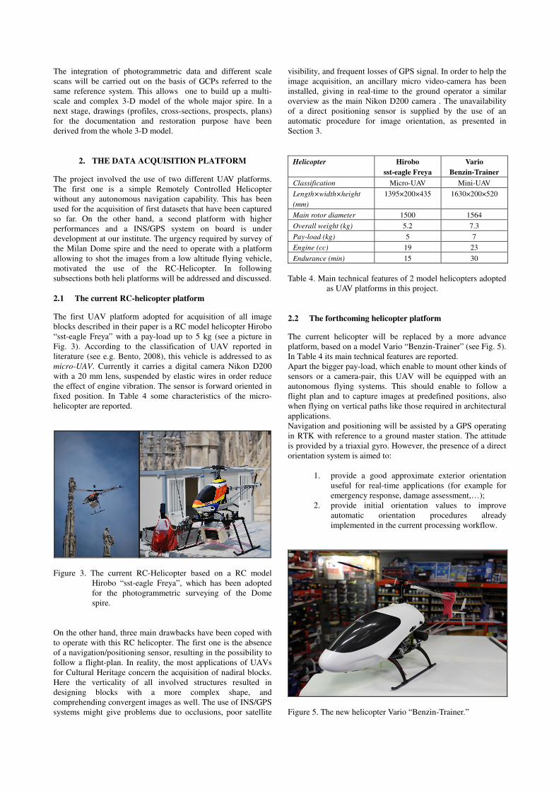
Figure 3. The current RC-Helicopter based on a RC model
Hirobo “sst-eagle Freya”, which has been adopted
for the photogrammetric surveying of the Dome
spire.
On the other hand, three main drawbacks have been coped with
to operate with this RC helicopter. The first one is the absence
of a navigation/positioning sensor, resulting in the possibility to
follow a flight-plan. In reality, the most applications of UAVs
for Cultural Heritage concern the acquisition of nadiral blocks.
Here the verticality of all involved structures resulted in
designing blocks with a more complex shape, and
comprehending convergent images as well. The use of INS/GPS
systems might give problems due to occlusions, poor satellite
visibility, and frequent losses of GPS signal. In order to help the
image acquisition, an ancillary micro video-camera has been
installed, giving in real-time to the ground operator a similar
overview as the main Nikon D200 camera . The unavailability
of a direct positioning sensor is supplied by the use of an
automatic procedure for image orientation, as presented in
Section 3.
Helicopter Hirobo
sst-eagle Freya
Vario
Benzin-Trainer
Classification Micro-UAV Mini-UAV
Length×width×height
(mm)
1395×200×435 1630×200×520
Main rotor diameter 1500 1564
Overall weight (kg) 5.2 7.3
Pay-load (kg) 5 7
Engine (cc) 19 23
Endurance (min) 15 30
Table 4. Main technical features of 2 model helicopters adopted
as UAV platforms in this project.
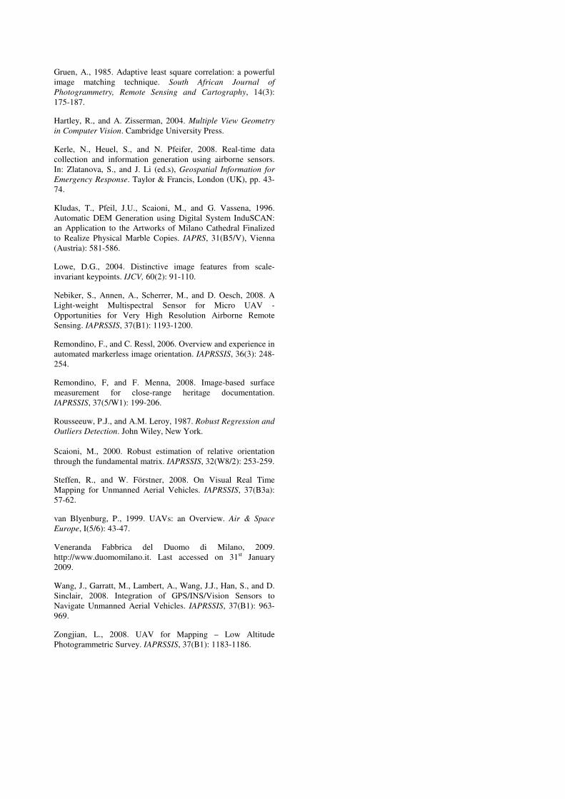
2.2 The forthcoming helicopter platform
The current helicopter will be replaced by a more advance
platform, based on a model Vario “Benzin-Trainer” (see Fig. 5).
In Table 4 its main technical features are reported.
Apart the bigger pay-load, which enable to mount other kinds of
sensors or a camera-pair, this UAV will be equipped with an
autonomous flying systems. This should enable to follow a
flight plan and to capture images at predefined positions, also
when flying on vertical paths like those required in architectural
applications.
Navigation and positioning will be assisted by a GPS operating
in RTK with reference to a ground master station. The attitude
is provided by a triaxial gyro. However, the presence of a direct
orientation system is aimed to:
1. provide a good approximate exterior orientation
useful for real-time applications (for example for
emergency response, damage assessment,…);
2. provide initial orientation values to improve
automatic orientation procedures already
implemented in the current processing workflow.
Figure 5. The new helicopter Vario “Benzin-Trainer.”

The digital camera will be installed on a stabilized and turnable
pay-load to capture images along different directions. A radio
connections will transmit all images to the ground station.
3. STRATEGY FOR IMAGE ORIENTATION
3.1 Overview on automatic image orientation
The UAV vehicles adopted during this project should operate in
several conditions and environments, which might feature
completely different scenarios. Even though the platform with
autonomous flight capability is still under development, high-
precision photogrammetric projects cannot simply rely on direct
orientation through GPS/INS sensors. A procedure to solve this
task plays a key-role in the processing workflow, even more at
the current stage.
As already mentioned in the introduction (Subsec. 1.3),
automatic orientation is a completely solved task in Aerial
Photogrammetry, but not in Close-range. Some low-cost
software can solve for the orientation of a generic image block
but using coded targets (e.g. iWitness, PhotoModeler).
Unfortunately, targeting requires temporary application of
markers on the object to survey, operation that in some cases is
complicated or impossible. The survey of Milan Dome spire is a
typical case when this happens.
Automatic orientation of marker-less image block is then an still
open issue in Photogrammetry, but also in Computer Vision
(CV). Both disciplines afford the same problem but with a
different mathematic and methodological approach. Also the
used sensors can be really different: in Photogrammetry high
resolution images are adopted, while in CV video-cameras are
employed and a huge number of short baseline frames must be
analyzed. Another difference is calibration: CV algorithms are
“uncalibrated”, that means that inner orientation parameter are
not necessary, while photogrammetric application need sensor
calibration.
In this paper a method integrating techniques of both disciplines
is presented. It makes use of photogrammetric procedures
during the image orientation phase, in order to provide an
accurate solution, but it also implements CV methods to
automate the procedure. In fact, a conjunct use of the methods
of both disciplines allows the resolution of some typical
problems of one with the other, and vice versa. Calibration
parameters must be known for the correct running of the
algorithm.
Either an image sequence or a generic image block can be
processed. The former case requires the acquisition of images in
a way that each image presents an overlap with the next two
images. The latter case is instead carried out with unorganized
images. The main difference between both cases is the
computational time: a sequence analysis is faster because the
order of images is a priori given, while in a generic block it
must be estimated with an exhaustive research in the whole
block. In the next sections both procedure are described.
The implemented strategy is referred to in literature as Structure
and Motion (S&M) or Structure from Motion. It is based on the
use of sequences made up of single images (likewise the present
application) or stereo-pairs (e.g. in MMT applications),
captured by a camera or a video camera. Consequent images in
a sequence usually show small differences between them, fact
that makes easier the search of corresponding points by image
matching algorithms. Homologous points are firstly searched in
close images by using geometric models typical of CV
(fundamental matrix, essential matrix, trifocal tensor); high
break-down robust estimator are applied at this stage to cope
with outliers (Rousseeuw & Leroy, 1987). In a second stage, if
needed, tie points are transferred along more images of the
sequence in order to find manifold points and to improve the
block reliability.
3.2 Sequence orientation with S&M algorithm
The automatic orientation of a sequence requires that each
image (i) presents an overlap with the next two ones (i+1, i+2).
This condition can be easily respected when a video is acquired,
while particular attention must be paid in case a camera is used.
The entire sequence is divided into triplets (images i, i+1, i+2 -
i+1, i+2, i+3 - …) and a feature-based matching (FBM) with
SIFT (Lowe, 2004) is carried out to identify homologous points
inside each triplet. Any mistakes that might remain is removed
by the robust estimation of the fundamental matrix (Hartley &
Zisserman, 2004) with Least Median of Squares technique
(Rousseeuw & Leroy, 1987). Details of this task can be found
in Scaioni (2000). The FBM with SIFT is highly time
consuming, then it is opportune to use only compressed images
(less than 1 Mpx) in order to speed up the process (see Fig. 6).
From these image coordinates, a refining with Least Squares
matching (LSM - Gruen, 1985) is carried out in order to use
also full resolution images and to improve the estimation of
image coordinates.
The orientation procedure is based on a progressive resection
alternated to intersection in order to concatenate all images to a
initial reconstruction of an image triplet assumed as reference
(generally the first one). This procedure is completely based on
collinearity equations and no CV orientation techniques are
used. This approach looks like the standard S&M procedure,
but the mathematical approach makes use of photogrammetric
methods. Further details about this algorithm can be found in
Barazzetti & Scaioni (2009).
Camera poses and 3-D points computed with this technique are
shown in figure 7. In this case only 11 images were analyzed
and some problems were found during the S&M approach
because these images do not form an ordered and regular
sequence. Indeed, the sequence analysis algorithm can present
some problems during processing of a block made up of several
strips. In fact, the procedure is useful when a sequence has a
“ring” shape, while it is complicated to determine homologous
points between non-consecutive images. The matching between
images of different strips is carried out by means of a search in
the object space and presents problems when the strips are not
regular, like in this case. This is the reason why a tool for
generic image block was implemented.
Figure 6. Matching between 3 consecutive triplets with SIFT.

Figure 7. Camera poses with the implemented algorithm for
image sequence analysis.
3.3 Orientation with the algorithm for generic image
blocks
The tool for generic image blocks makes use of an exhaustive
search of tie points between all possible image pair
combinations. In particular, a FBM with SIFT is carried out
between compressed image pairs, then a LSM refining is carried
out to use original full resolution images.
For a block of n images, this search strategy results in (n2-n)/2
tries. With a sequence made up of 50 images compressed into
VGA quality, the algorithm needs 1.7 hours for the matching
phase. In case images form an ordered sequence, the time for
the same block is 4 minutes only due to its linear computational
cost with respect to the image number. This is the reason why
when images are taken with a “ring” configuration the algorithm
of section 3.2 results faster.
The graphical user interface of the algorithm is shown in figure
8. The code is developed in Fortran (LSM algorithm), standard
C (FBM) and MATLAB®. The parts selected with a red
rectangle on the GUI form the generic image block algorithm.
The block analyzed with the proposed method is composed of
78 images. The matching phase needed 4 hours roughly and
more than 16000 points were automatically matched. Also in
this case, mismatched points were removed with the robust
estimation of the fundamental matrix. In figure 9 results before
the outlier removal are shown: with the Lowe descriptor 120
matches were found, while the robust estimation of the epipolar
geometry selected 89 points. Figure 10 reports the estimated
camera poses with compressed images
A bundle adjustment was carried out with compressed images
only, in order to check the quality of the FBM. The algorithm
used in this step is the same PhotoModeler bundle procedure. In
fact PhotoModeler can be used in a Dynamic Data Exchange
modality. This means that it is sufficient to develop a code
which enables one to control the software for using all main
capabilities of PhotoModeler with a remote connection.
Manual operations are thus not necessary. In any case, this
bundle algorithm is only a temporary solution. However, it gave
useful results for many applications and the only limit is the
lack of a complete statistical output. In addition, PhotoModeler
offers an user friendly interface for visual analysis and allows
one to save the data in several formats.
Figure 8. The GUI of the algorithm. In red the function
concerning a generic image block.
Figure 9. An image pair before (top) and after (bottom) the
robust estimation of camera poses: many outliers
have been correctly removed.
Figure 10 also shows an image redundancy. For this reason only
29 images were selected for further next elaborations. The LSM
refining allowed one to use full resolution images and 6000
points were matched.
The bundle adjustment with these image coordinates allowed a
free net analysis of the block and a scale factor was then fixed.
The model was roto-translated to set the axis x and y (y is
vertical) on the façade, while z represents the depth.

Figure 10. Orientation result of compressed images.
In any case, the procedure cannot be considered now
completely automatic. In fact after the bundle adjustment few
points were manually removed. This manual correction required
no more than few minutes to identify these gross errors, but in
any case was necessary. Globally 10-15 points were classified
as outliers. The bundle adjustment was also performed by using
image points which belong to 4 images (at least). This choice is
motivated by the large overlap of this image block and made
more reliable the block.
In future development of the algorithm a benchmarking
technique on the bundle adjustment result will be implemented
(Dickscheid et al., 2008).
The average theoretical precision of this survey is σx = ± 2.4
mm, σy = ± 1.6 mm and σz = ± 7.5 mm and 486 object points
were found.
4. OBJETC RECONSTRUCTION
4.1 Point cloud creation with PhotoModeler
The last version of PhotoModeler 6 has a “Scanner” (Eos
Systems, 2009) tool for point cloud extraction with dense
matching algorithm. This tool works with image pairs only but
seems to be able to provide a good dense point cloud.
In this sense, PhotoModeler Scanner is the first low-cost
photogrammetric package which allows the point cloud
extraction from images (see. figure 11). Although very slow,
results are good (especially if compared with the prize of other
more expensive commercial packages capable to create and
manage point clouds). The reconstruction is often good where
planar elements are located, while some problem occurs in
correspondence of more complex elements. Sometimes
systematic errors are found.
Figure 11. Some example of point clouds created with
PhotoModeler 6 Scanner. Point spacing varies from
5 to 10 mm.

5. FINAL CONSIDERATIONS AND FUTURE WORKS
5.1 Considerations on the achieved results and future
work
The paper presented the current photogrammetric workflow
applied for the survey and 3-D reconstruction of the Milan
Dome main spire. To cope effectively with the high-rising
character of the building, a RC model helicopter equipped with
a digital camera Nikon D200 was adopted. The final 3-D model
will result from the integration of photogrammetric data with
different scale TLS surveys.
The current UAV platform is not provided by
navigation/positioning sensors, than it cannot be used in
autonomous way. The main consequence of this drawback is the
irregular shape of the resulting image block, as can be seen in
figure 10. To guarantee enough coverage on the object for a
complete surface reconstruction, a highly redundant number of
images was captured.
Image orientation is achieved through an automatic procedure
based on a Structure and Motion strategy extended to work also
with block having a general shape and not only with sequences.
The algorithm is based on CV methods integrated to
photogrammetric bundle adjustment to compute final
orientation. Also with the forthcoming availability of a second
UAV with autonomous navigation capability and with direct
orientation recording, this procedure will remain important to
increase precision and reliability of the final result.
Object reconstruction is currently at a initial stage. Indeed,
some experiments with a commercial low-cost photogrammetric
software have been tried. Results are encouraging, even though
the method should be improved by using more efficient and
reliable dense matching techniques (multiphoto with geometric
constraints - Baltsavias, 1991). Alternative solutions have to be
found either in commercial and existing packages (Remondino
& Menna, 2008), and in software implemented internally at
SITE research group.
The workflow presented along the paper and discussed in this
subsection 5.1 will enable to obtain the 3-D surface
reconstruction of the whole Cathedral’s spire and its basement
on the roof of the church. This result is relevant, because it will
offer a durable digital documentation of the current as-built
state. In 1996 the most advanced photogrammetric technology
was applied to get the reconstruction of a single statue (Kludas
et al., 1996). What can be obtained with relative ease today is
not comparable to that results, considering the cheaper cost of
SW and HD, and the reduced time for data processing.
5.2 Open issues
To complete and improve the workflow described above is
needed a lot of work, some to get the alignment with the state of
the art, some to develop technical aspects typical of this specific
application.
The real challenge is represented by two innovative aspects.
The first one concern the automation of data acquisition by
means of autonomous and intelligent UAVs, which are capable
to define its flight-plan and to follow it so that a full coverage of
the object is achieved.
The second main open issue is the automatic object modelling
and understanding. On the other hand, a correct data acquisition
(platform, sensor, block design and data capture) and a fast and
robust orientation procedure (included sensors and integrated
systems calibration) allow to have good images to extract
information. However, at the current state of the art of
photogrammetry information is derived manually, with a still
stronger human contribute. Exception is given by surface
modelling, even though also dense matching algorithm don not
give any semantic interpretation. Disregarding consideration
about data quality, the full photogrammetric process gives more
or less the same finding that a TLS could, if applicable. The real
frontier of Photogrammetry is given by the development of
cognitive systems that are capable to understand the semantic
meaning of a geometric shape of an object, and then to guide its
reconstruction and modelling.
AKNOWLEDGEMENTS
The authors would like to thank the Milan Cathedral
“architect”, Ing. Benigno Mörlin Visconti Castiglione.
Aknowledgements also go to Prof. Carlo Monti (Politecnico di
Milano, BEST/SITE Dept.) for supporting and coordinating this
project.
REFERENCES
Baltsavias, E.P., 1991. Geometrically Constrained Multiphoto
Matching. Mitteilungen No. 49, Institute of Geodesy and
Photogrammetry, ETH, Zurich.
Barazzetti, L., and M. Scaioni, 2009. Automatic orientation of
image sequences for 3-D object reconstruction: first results of a
method integrating photogrammetric and computer vision
algorithms. IAPRSSIS, 37(5/W1): 8 pp.
Bendea, H.F., Chiabrando, F., Tonolo, F.G., and D.
Marenchino, 2007. Mapping of archaeological areas using a
low-cost UAV the Augusta Bagiennorum Test site. In Proc. Of
XXI Int. CIPA Symp, Athens, Greece, on CDROM.
Bento, M. D. F., 2008. Unmanned Aerial Vehicles: an
Overview. InsideGNSS (Jan/Feb 2008): 54-61.
Colomina, I., Blázquez, M., Molina, P., Parés, M.E., and M.
Wis, 2008. Towards a New Paradigm for High-Resolution Low-
Cost Photogrammetry and Remote Sensing. IAPRSSIS, 37(B1):
1201-1206.
Dickscheid, T., Läbe, T., and W. Förstner, 2008. Benchmarking
Automatic Bundle Adjustment Results. IAPRSSIS, 37(B3a): 7-
12.
Eisenbeiss, H., 2004. A mini unmanned aerial vehicle (UAV):
system overview and image acquisition. IAPRSSIS, 36(5/W1),
on CD-ROM, 6 pp.
Eisenbeiss, H., 2008. The Autonomous Mini Helicopter: a
Powerful Platform for Mobile Mapping. IAPRSSIS, 37(B1):
977-983.
Eos Systems, 2009. http://www.photomodeler.com. Last
accessed on 31st January 2009.
Eugster, H., and S. Nebiker, 2008. UAV-Based Augmented
Monitoring – Real-Time Georeferencing and Integration of
Video Imagery with Virtual Globes. IAPRSSIS, 37(B1): 1229-
1235.
Grenzdörffer, G.J., Engel, A., and B. Teichert, 2008. The
Photogrammetric Potential of Low-Cost UAVs in Forestry and
Agriculture. IAPRSSIS, 37(B1): 1207-1213.
Gruen, A., 1985. Adaptive least square correlation: a powerful
image matching technique. South African Journal of
Photogrammetry, Remote Sensing and Cartography, 14(3):
175-187.
Hartley, R., and A. Zisserman, 2004. Multiple View Geometry
in Computer Vision. Cambridge University Press.
Kerle, N., Heuel, S., and N. Pfeifer, 2008. Real-time data
collection and information generation using airborne sensors.
In: Zlatanova, S., and J. Li (ed.s), Geospatial Information for
Emergency Response. Taylor & Francis, London (UK), pp. 43-
74.
Kludas, T., Pfeil, J.U., Scaioni, M., and G. Vassena, 1996.
Automatic DEM Generation using Digital System InduSCAN:
an Application to the Artworks of Milano Cathedral Finalized
to Realize Physical Marble Copies. IAPRS, 31(B5/V), Vienna
(Austria): 581-586.
Lowe, D.G., 2004. Distinctive image features from scale-
invariant keypoints. IJCV, 60(2): 91-110.
Nebiker, S., Annen, A., Scherrer, M., and D. Oesch, 2008. A
Light-weight Multispectral Sensor for Micro UAV -
Opportunities for Very High Resolution Airborne Remote
Sensing. IAPRSSIS, 37(B1): 1193-1200.
Remondino, F., and C. Ressl, 2006. Overview and experience in
automated markerless image orientation. IAPRSSIS, 36(3): 248-
254.
Remondino, F, and F. Menna, 2008. Image-based surface
measurement for close-range heritage documentation.
IAPRSSIS, 37(5/W1): 199-206.
Rousseeuw, P.J., and A.M. Leroy, 1987. Robust Regression and
Outliers Detection. John Wiley, New York.
Scaioni, M., 2000. Robust estimation of relative orientation
through the fundamental matrix. IAPRSSIS, 32(W8/2): 253-259.
Steffen, R., and W. Förstner, 2008. On Visual Real Time
Mapping for Unmanned Aerial Vehicles. IAPRSSIS, 37(B3a):
57-62.
van Blyenburg, P., 1999. UAVs: an Overview. Air & Space
Europe, I(5/6): 43-47.
Veneranda Fabbrica del Duomo di Milano, 2009.
http://www.duomomilano.it. Last accessed on 31st January
2009.
Wang, J., Garratt, M., Lambert, A., Wang, J.J., Han, S., and D.
Sinclair, 2008. Integration of GPS/INS/Vision Sensors to
Navigate Unmanned Aerial Vehicles. IAPRSSIS, 37(B1): 963-
969.
Zongjian, L., 2008. UAV for Mapping – Low Altitude
Photogrammetric Survey. IAPRSSIS, 37(B1): 1183-1186.