||Autonomous Systems Lab
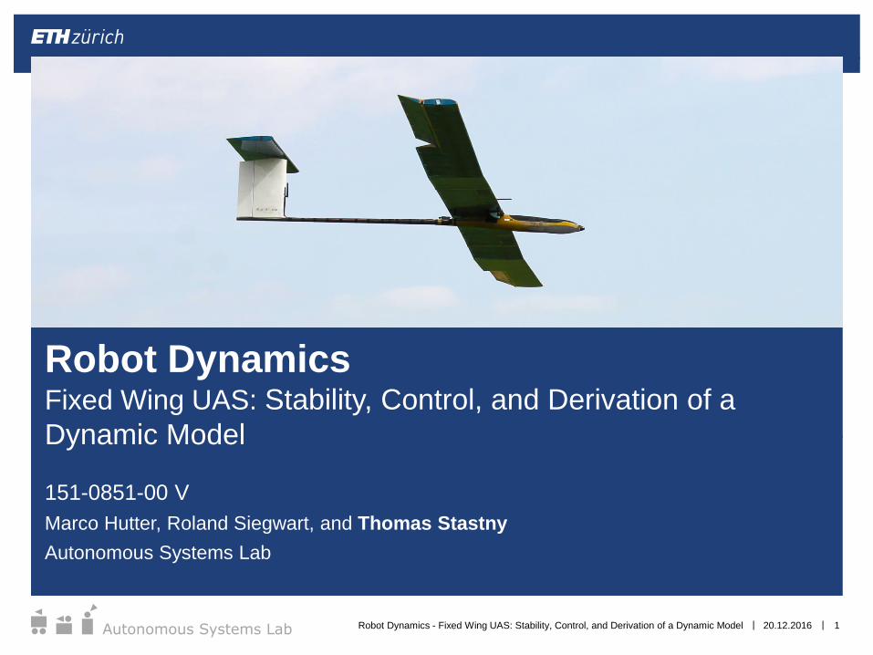
151-0851-00 V
Marco Hutter, Roland Siegwart, and Thomas Stastny
Autonomous Systems Lab
20.12.2016Robot Dynamics - Fixed Wing UAS: Stability, Control, and Derivation of a Dynamic Model 1
Robot DynamicsFixed Wing UAS: Stability, Control, and Derivation of a
Dynamic Model
||Autonomous Systems Lab
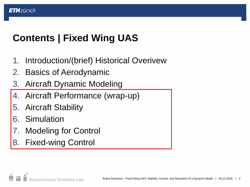
1. Introduction/(brief) Historical Overivew
2. Basics of Aerodynamic
3. Aircraft Dynamic Modeling
4. Aircraft Performance (wrap-up)
5. Aircraft Stability
6. Simulation
7. Modeling for Control
8. Fixed-wing Control
Contents | Fixed Wing UAS
20.12.2016 2Robot Dynamics - Fixed Wing UAS: Stability, Control, and Derivation of a Dynamic Model
||Autonomous Systems Lab 20.12.2016 3
Aircraft Performance (Wrap-up)
Robot Dynamics - Fixed Wing UAS: Stability, Control, and Derivation of a Dynamic Model
||Autonomous Systems Lab
We previously made some simplifications in the exercise
with assumptions of “steady” and “level” flight.
Steady =>
Level =>
Aircraft Performance | Powered vs. Un-powered
Flight
20.12.2016 4Robot Dynamics - Fixed Wing UAS: Stability, Control, and Derivation of a Dynamic Model
||Autonomous Systems Lab
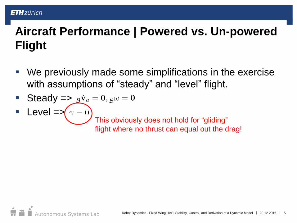
We previously made some simplifications in the exercise
with assumptions of “steady” and “level” flight.
Steady =>
Level =>
Aircraft Performance | Powered vs. Un-powered
Flight
20.12.2016 5
This obviously does not hold for “gliding”
flight where no thrust can equal out the drag!
Robot Dynamics - Fixed Wing UAS: Stability, Control, and Derivation of a Dynamic Model
||Autonomous Systems Lab
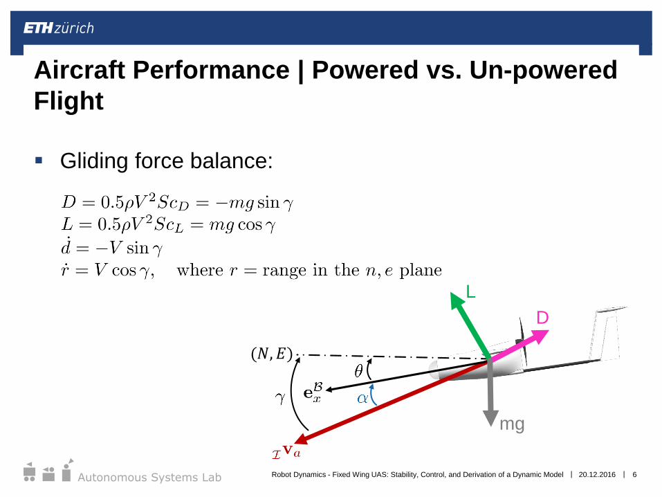
Gliding force balance:
Aircraft Performance | Powered vs. Un-powered
Flight
20.12.2016 6
(𝑁, 𝐸)
L
D
mg
Robot Dynamics - Fixed Wing UAS: Stability, Control, and Derivation of a Dynamic Model
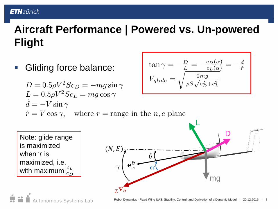
||Autonomous Systems Lab
Gliding force balance:
Aircraft Performance | Powered vs. Un-powered
Flight
20.12.2016 7
(𝑁, 𝐸)
L
D
mg
Note: glide range
is maximized
when is
maximized, i.e.
with maximum
Robot Dynamics - Fixed Wing UAS: Stability, Control, and Derivation of a Dynamic Model
||Autonomous Systems Lab
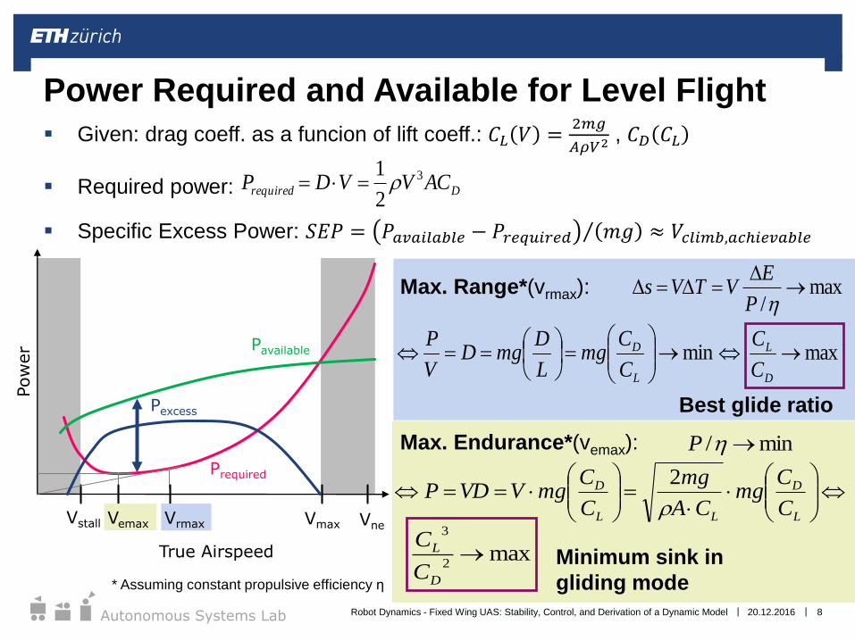
Given: drag coeff. as a funcion of lift coeff.: 𝐶𝐿 𝑉 =2𝑚𝑔
𝐴𝜌𝑉2 , 𝐶𝐷 𝐶𝐿
Required power:
Specific Excess Power: 𝑆𝐸𝑃 = 𝑃𝑎𝑣𝑎𝑖𝑙𝑎𝑏𝑙𝑒 − 𝑃𝑟𝑒𝑞𝑢𝑖𝑟𝑒𝑑 𝑚𝑔 ≈ 𝑉𝑐𝑙𝑖𝑚𝑏,𝑎𝑐ℎ𝑖𝑒𝑣𝑎𝑏𝑙𝑒
20.12.2016 8
Power Required and Available for Level Flight
Drequired ACVVDP 3
2
1
Pavailable
Prequired
Pexcess
Vstall Vmax Vne
Pow
er
True Airspeed
Vemax Vrmax
min
L
D
C
Cmg
L
DmgD
V
Pmax
D
L
C
C
Best glide ratio
max/
P
EVTVs
min/ P
max2
3
D
L
C
C
L
D
LL
D
C
Cmg
CA
mg
C
CmgVVDP
2
Minimum sink in
gliding mode
Max. Range*(vrmax):
Max. Endurance*(vemax):
* Assuming constant propulsive efficiency η
Robot Dynamics - Fixed Wing UAS: Stability, Control, and Derivation of a Dynamic Model
||Autonomous Systems Lab
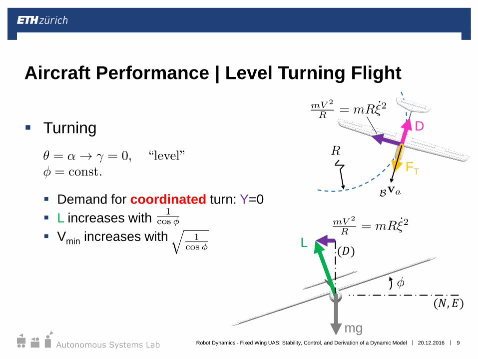
Turning
Demand for coordinated turn: Y=0
L increases with
Vmin increases with
Aircraft Performance | Level Turning Flight
20.12.2016 9
(𝑁, 𝐸)
D
FT
L(𝐷)
mgRobot Dynamics - Fixed Wing UAS: Stability, Control, and Derivation of a Dynamic Model
||Autonomous Systems Lab
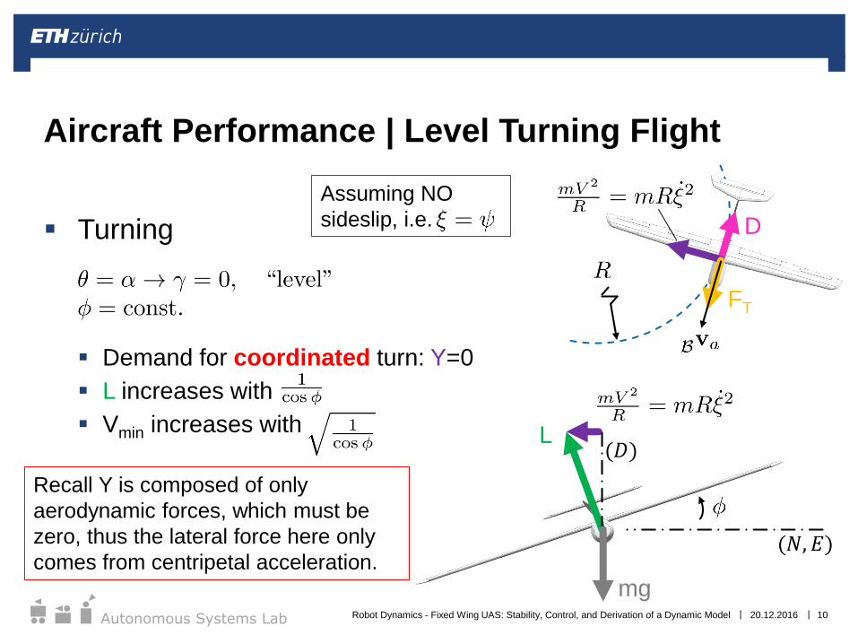
Turning
Demand for coordinated turn: Y=0
L increases with
Vmin increases with
Aircraft Performance | Level Turning Flight
20.12.2016 10
(𝑁, 𝐸)
D
Assuming NO
sideslip, i.e.
FT
L(𝐷)
mg
Recall Y is composed of only
aerodynamic forces, which must be
zero, thus the lateral force here only
comes from centripetal acceleration.
Robot Dynamics - Fixed Wing UAS: Stability, Control, and Derivation of a Dynamic Model
||Autonomous Systems Lab
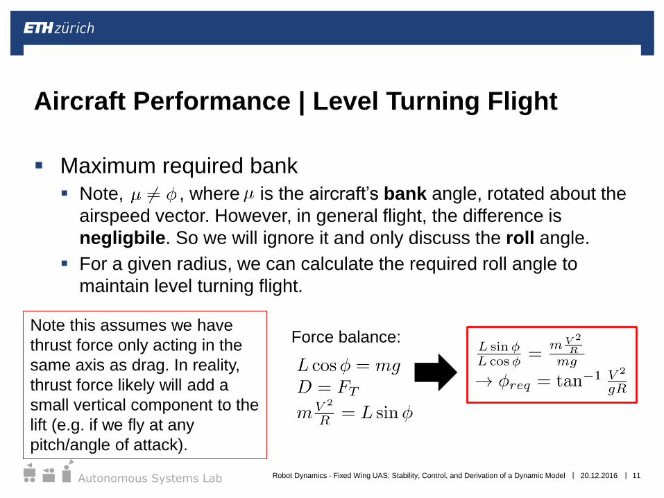
Maximum required bank
Note, , where is the aircraft’s bank angle, rotated about the
airspeed vector. However, in general flight, the difference is
negligbile. So we will ignore it and only discuss the roll angle.
For a given radius, we can calculate the required roll angle to
maintain level turning flight.
Aircraft Performance | Level Turning Flight
20.12.2016 11
Force balance:Note this assumes we have
thrust force only acting in the
same axis as drag. In reality,
thrust force likely will add a
small vertical component to the
lift (e.g. if we fly at any
pitch/angle of attack).
Robot Dynamics - Fixed Wing UAS: Stability, Control, and Derivation of a Dynamic Model
||Autonomous Systems Lab 20.12.2016 12
Aircraft Stability
Robot Dynamics - Fixed Wing UAS: Stability, Control, and Derivation of a Dynamic Model
||Autonomous Systems Lab
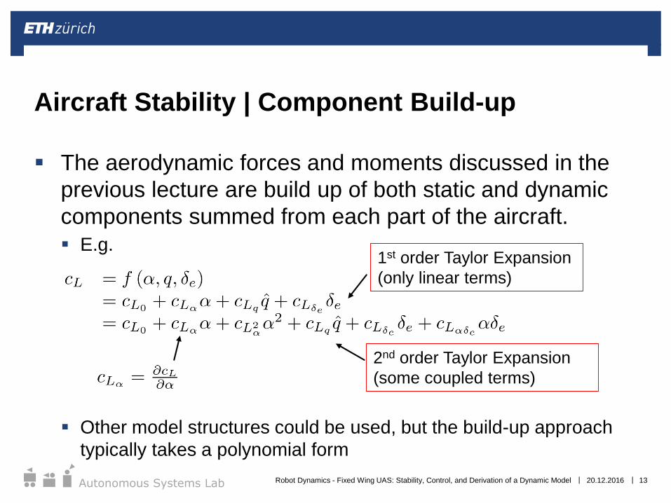
The aerodynamic forces and moments discussed in the
previous lecture are build up of both static and dynamic
components summed from each part of the aircraft.
E.g.
Other model structures could be used, but the build-up approach
typically takes a polynomial form
Aircraft Stability | Component Build-up
20.12.2016 13
1st order Taylor Expansion
(only linear terms)
2nd order Taylor Expansion
(some coupled terms)
Robot Dynamics - Fixed Wing UAS: Stability, Control, and Derivation of a Dynamic Model

||Autonomous Systems Lab
It is standard practice to non-dimensionalize rate
coefficients per operating airspeed and aircraft geometry
For example, using span in the lateral-directional derivatives:
…and mean geometric chord in the longitudinal derivatives:
Aircraft Stability | Non-dimensionalization
20.12.2016 14Robot Dynamics - Fixed Wing UAS: Stability, Control, and Derivation of a Dynamic Model
||Autonomous Systems Lab
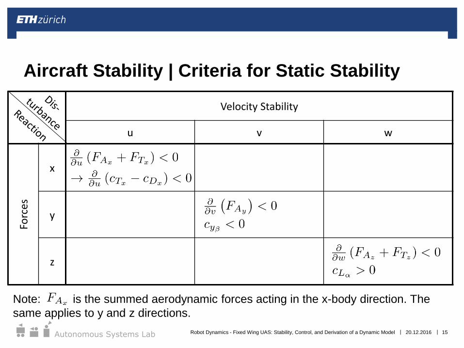
Aircraft Stability | Criteria for Static Stability
Velocity Stability
u v w
Forces
x
y
z
20.12.2016 15
Note: is the summed aerodynamic forces acting in the x-body direction. The
same applies to y and z directions.
Robot Dynamics - Fixed Wing UAS: Stability, Control, and Derivation of a Dynamic Model

||Autonomous Systems Lab
Aircraft Stability | Criteria for Static Stability
Directional Stability Rotational Stability
b a p q r
Torques
roll
pitch
yaw
20.12.2016 16Robot Dynamics - Fixed Wing UAS: Stability, Control, and Derivation of a Dynamic Model
||Autonomous Systems Lab
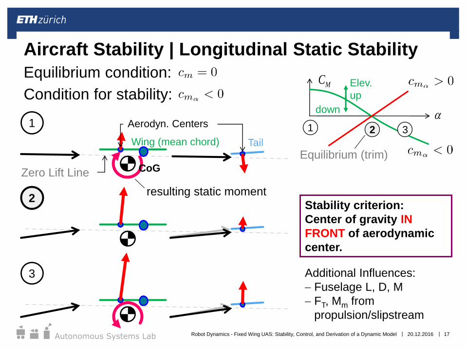
Aircraft Stability | Longitudinal Static Stability
Equilibrium condition:
Condition for stability:
a
MC
2
3
1 2 3Aerodyn. Centers
Wing (mean chord) Tail
Zero Lift Line CoG
1
Equilibrium (trim)
Additional Influences:
Fuselage L, D, M
FT, Mm from
propulsion/slipstream
Stability criterion:
Center of gravity IN
FRONT of aerodynamic
center.
Elev.
up
down
20.12.2016 17
resulting static moment
Robot Dynamics - Fixed Wing UAS: Stability, Control, and Derivation of a Dynamic Model

||Autonomous Systems Lab
Aircraft Stability | Statics vs. DynamicsDynamic stabilityStatic stability
Disturbance Aerodyn.
reaction
torque
No reaction
torque
Stable
Neutral
Aerodyn.
reaction
torqueUnstable
Stable
Neutral
Unstable
Tre
ate
d w
ith
aero
dyn
am
ic d
eri
vati
va
Mo
delin
g o
f th
e d
yn
am
ics r
eq
uir
ed
20.12.2016 18
Disturbance
Disturbance
Robot Dynamics - Fixed Wing UAS: Stability, Control, and Derivation of a Dynamic Model

||Autonomous Systems Lab 20.12.2016 19
Simulation
Robot Dynamics - Fixed Wing UAS: Stability, Control, and Derivation of a Dynamic Model
||Autonomous Systems Lab
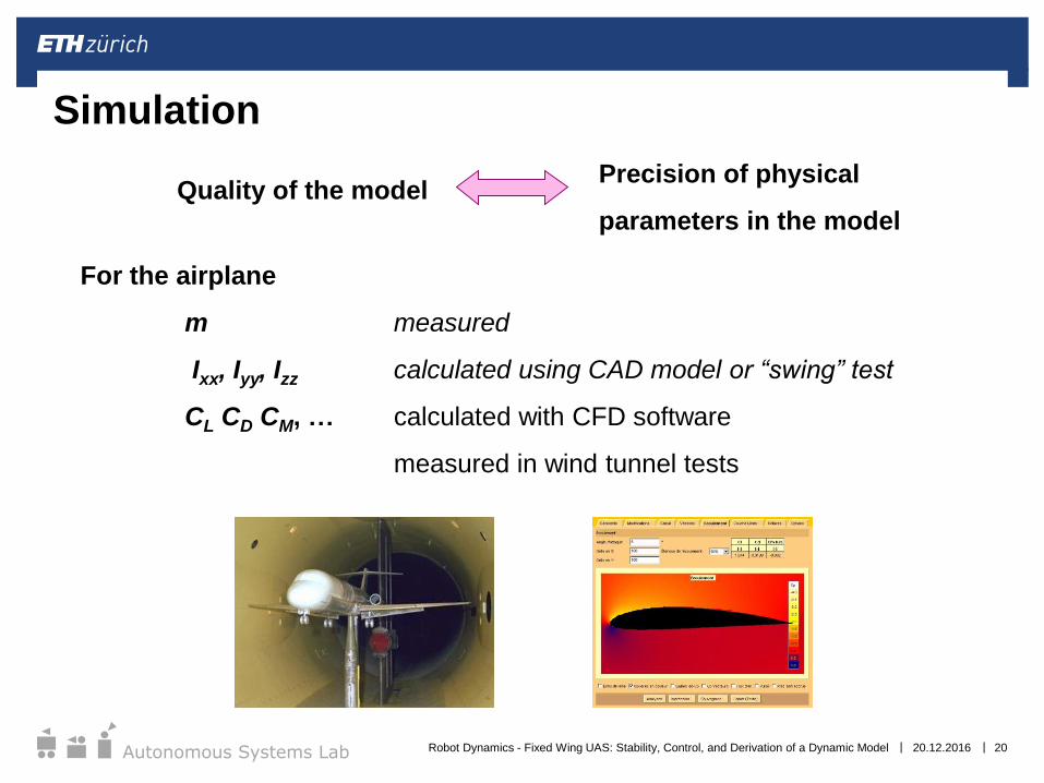
Simulation
For the airplane
m measured
Ixx, Iyy, Izz calculated using CAD model or “swing” test
CL CD CM, … calculated with CFD software
measured in wind tunnel tests
Precision of physical
parameters in the modelQuality of the model
20.12.2016 20Robot Dynamics - Fixed Wing UAS: Stability, Control, and Derivation of a Dynamic Model

||Autonomous Systems Lab
10m260m
Simulation | Sky Sailor
Behaviour in open-loop:
• Natural Stability
• Flight speed, glide slope
very close to reality
Initial condition:
• Roll 0°, Pitch -12°, Yaw 0°
• Speed 8.2 m/s
• Control surfaces at 0°
• Motor off
Stabilized after ~50 s
Flight speed ~8.2 m/s
Glide Ratio ~26
20.12.2016 21Robot Dynamics - Fixed Wing UAS: Stability, Control, and Derivation of a Dynamic Model
||Autonomous Systems Lab 20.12.2016 22
Simulation | Sky Sailor
We will investigate more of Sky Sailor’s dynamics in
tomorrow’s exercise.
Robot Dynamics - Fixed Wing UAS: Stability, Control, and Derivation of a Dynamic Model
||Autonomous Systems Lab 20.12.2016 23
Modeling for Control
Robot Dynamics - Fixed Wing UAS: Stability, Control, and Derivation of a Dynamic Model

||Autonomous Systems Lab
Control of airplanes is not easy:
Inherently non-linear
Low control authority
Actuator saturation
„double integrator“ characteristics
MIMO: 4 inputs, 6 DoF, thus underactuated
Modeling for Control | Introduction
20.12.2016 24Robot Dynamics - Fixed Wing UAS: Stability, Control, and Derivation of a Dynamic Model
||Autonomous Systems Lab
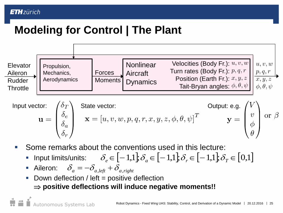
Some remarks about the conventions used in this lecture:
Input limits/units:
Aileron:
Down deflection / left = positive deflection
positive deflections will induce negative moments!!
Modeling for Control | The Plant
Velocities (Body Fr.):
Turn rates (Body Fr.):
Position (Earth Fr.):
Tait-Bryan angles:
Nonlinear
Aircraft
Dynamics
Forces
Moments
Propulsion,
Mechanics,
Aerodynamics
Elevator
Aileron
Rudder
Throttle
State vector:
1,0;1,1;1,1;1,1 Trae
rightaleftaa ,,
20.12.2016 25
Output: e.g.Input vector:
Robot Dynamics - Fixed Wing UAS: Stability, Control, and Derivation of a Dynamic Model
||Autonomous Systems Lab
Modeling for Control | The (Linearized) Plant
Δu, Δw;
Δq;
ΔT
e
Longitudinal
Plantr
a
Lateral
Plant
im
re
2
-2
-2
Short Period
Mode:
ω = 5 rad/s
Phugoid
Mode:
ω = 0.6 rad/s
im
re
4
-4
-4
Roll Subsidence
Mode
Spiral Mode
Dutch Roll
Mode
ω = 5 rad/s
Corresponding Poles (Aerobatic Model Airplane)
Subsystem
20.12.2016 26Robot Dynamics - Fixed Wing UAS: Stability, Control, and Derivation of a Dynamic Model
||Autonomous Systems Lab
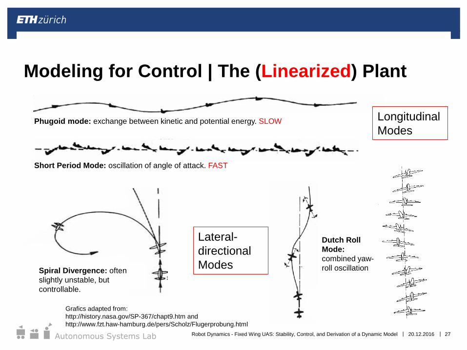
Modeling for Control | The (Linearized) Plant
Short Period Mode: oscillation of angle of attack. FAST
Phugoid mode: exchange between kinetic and potential energy. SLOW
Spiral Divergence: often
slightly unstable, but
controllable.
Dutch Roll
Mode:
combined yaw-
roll oscillation
Grafics adapted from:
http://history.nasa.gov/SP-367/chapt9.htm and
http://www.fzt.haw-hamburg.de/pers/Scholz/Flugerprobung.html
20.12.2016 27
Longitudinal
Modes
Lateral-
directional
Modes
Robot Dynamics - Fixed Wing UAS: Stability, Control, and Derivation of a Dynamic Model
||Autonomous Systems Lab 20.12.2016 28
Fixed-wing Control
Robot Dynamics - Fixed Wing UAS: Stability, Control, and Derivation of a Dynamic Model
||Autonomous Systems Lab
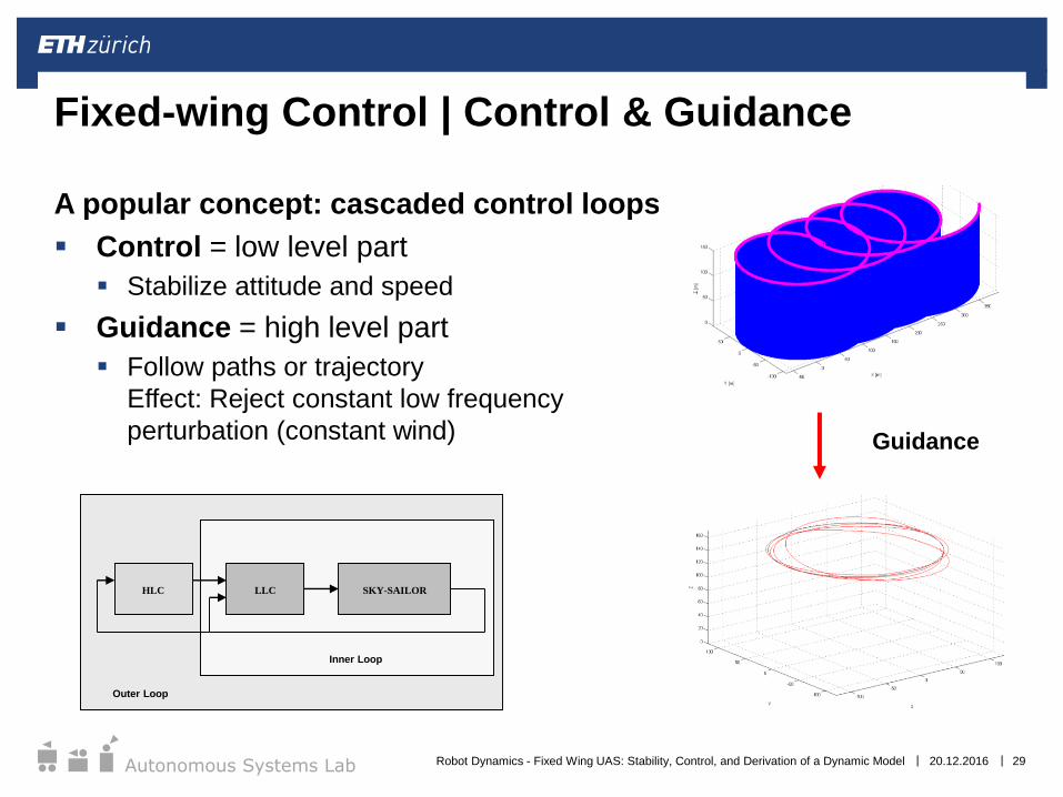
A popular concept: cascaded control loops
Control = low level part
Stabilize attitude and speed
Guidance = high level part
Follow paths or trajectory
Effect: Reject constant low frequency
perturbation (constant wind)
Fixed-wing Control | Control & Guidance
Guidance
SKY-SAILORLLCHLC
Inner Loop
Outer Loop
20.12.2016 29Robot Dynamics - Fixed Wing UAS: Stability, Control, and Derivation of a Dynamic Model
||Autonomous Systems Lab
Many control techniques :
Cascaded PID loops
Optimal Control
Robust Control
…
The chosen control techniques determined according to:
Computational Power
Type of flight (aerobatics - level flight)
Fixed-wing Control | Control Concepts
20.12.2016 30Robot Dynamics - Fixed Wing UAS: Stability, Control, and Derivation of a Dynamic Model
||Autonomous Systems Lab
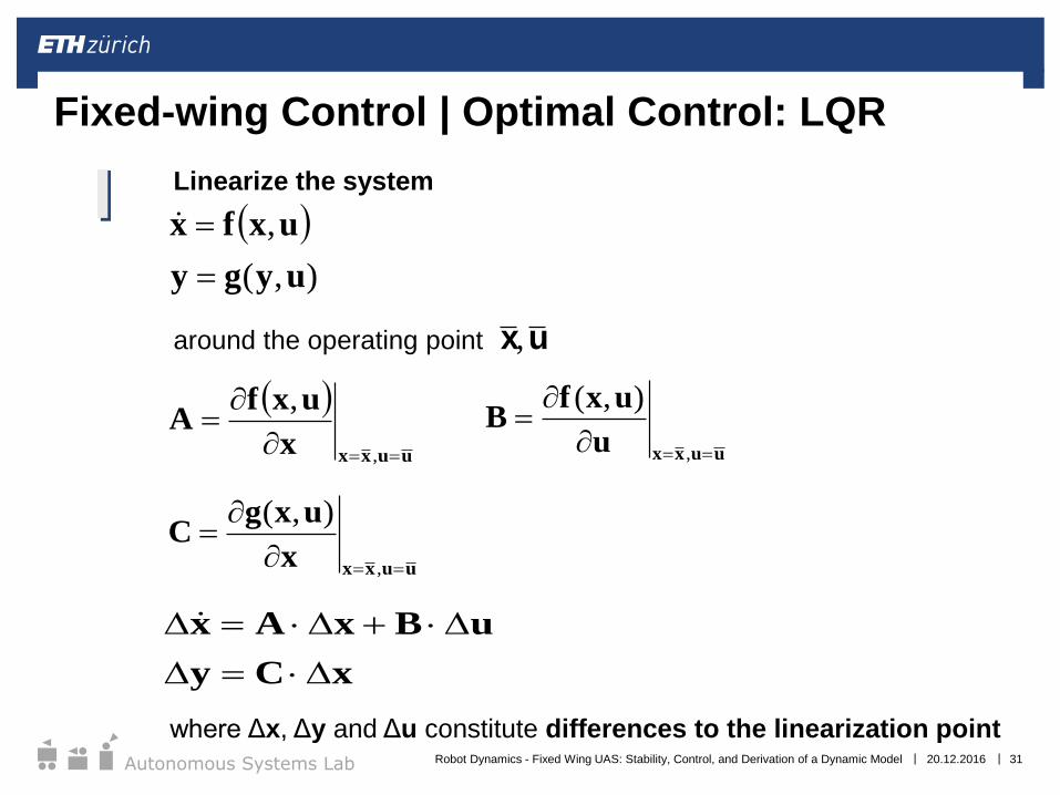
Fixed-wing Control | Optimal Control: LQR
I Linearize the system
around the operating point
xCy
uBxAx
uuxxx
uxfA
,
,
uuxxu
uxfB
,
),(
),(
,
uygy
uxfx
uuxxx
uxgC
,
),(
x,u
where Δx, Δy and Δu constitute differences to the linearization point20.12.2016 31Robot Dynamics - Fixed Wing UAS: Stability, Control, and Derivation of a Dynamic Model

||Autonomous Systems Lab
Fixed-wing Control | Optimal Control: LQR
I Linearize the system
around the operating point
xCy
uBxAx
uuxxx
uxfA
,
,
uuxxu
uxfB
,
),(
),(
,
uygy
uxfx
uuxxx
uxgC
,
),(
x,u
where Δx, Δy and Δu constitute differences to the linearization point20.12.2016 32Robot Dynamics - Fixed Wing UAS: Stability, Control, and Derivation of a Dynamic Model
||Autonomous Systems Lab
Fixed-wing Control | Optimal Control: LQR
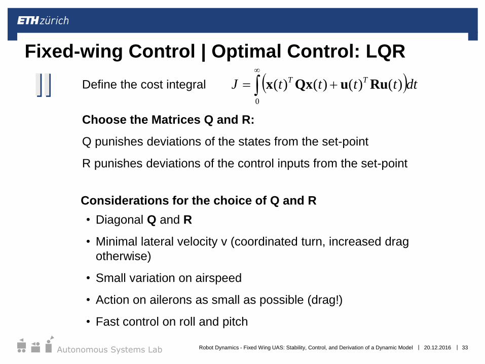
II Define the cost integral
Choose the Matrices Q and R:
Q punishes deviations of the states from the set-point
R punishes deviations of the control inputs from the set-point
0
)()()()( dtttttJ TTRuuQxx
Considerations for the choice of Q and R
• Diagonal Q and R
• Minimal lateral velocity v (coordinated turn, increased drag
otherwise)
• Small variation on airspeed
• Action on ailerons as small as possible (drag!)
• Fast control on roll and pitch
20.12.2016 33Robot Dynamics - Fixed Wing UAS: Stability, Control, and Derivation of a Dynamic Model

||Autonomous Systems Lab
Fixed-wing Control | Optimal Control: LQR
III )()( tt xKu Find the corresponding control law
By solving the (algebraic) Matrix-Riccatti Equation
(for P and K):
(use MATLAB…)
PBRK
0QPBPBRPAPA
T
TT
1
1
20.12.2016 34Robot Dynamics - Fixed Wing UAS: Stability, Control, and Derivation of a Dynamic Model
||Autonomous Systems Lab
Problems:
Non-linear effects when further away from operating point
Computation Costs arising from:
Linearization
Solution to Riccatti Equation:
Too expensive, cannot be done on-line
Way out: compute gains off-line as a look-up table
for discretized state space: Gain-Scheduling
Fixed-wing Control | Optimal Control: LQR
20.12.2016 35Robot Dynamics - Fixed Wing UAS: Stability, Control, and Derivation of a Dynamic Model

||Autonomous Systems Lab
Attitude
Controller
1 PI with anti-reset wind-up2
Gain scaled with 1/VT2
Body Rate
Controller
rd
qd
pdD
2
D2
D2
Fixed-wing Control | Simple Cascaded Control
Airplane
Dynamics
rudd
elev
ail
y
PI1
PI1d
Constrain to
coordinated turn:
Jr
thr
• Bandwidths of inner Loops must
be sufficiently larger!
Trajectory
Generation
and
Guidance
20.12.2016 36Robot Dynamics - Fixed Wing UAS: Stability, Control, and Derivation of a Dynamic Model
||Autonomous Systems Lab
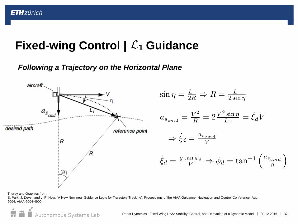
Fixed-wing Control | Guidance
20.12.2016 37
Theroy and Graphics from:
S. Park, J. Deyst, and J. P. How, “A New Nonlinear Guidance Logic for Trajectory Tracking”, Proceedings of the AIAA Guidance, Navigation and Control Conference, Aug
2004. AIAA-2004-4900
Following a Trajectory on the Horizontal Plane
Robot Dynamics - Fixed Wing UAS: Stability, Control, and Derivation of a Dynamic Model
||Autonomous Systems Lab 20.12.2016 38
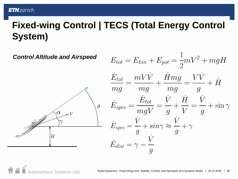
Fixed-wing Control | TECS (Total Energy Control
System)
Control Altitude and Airspeed
Robot Dynamics - Fixed Wing UAS: Stability, Control, and Derivation of a Dynamic Model
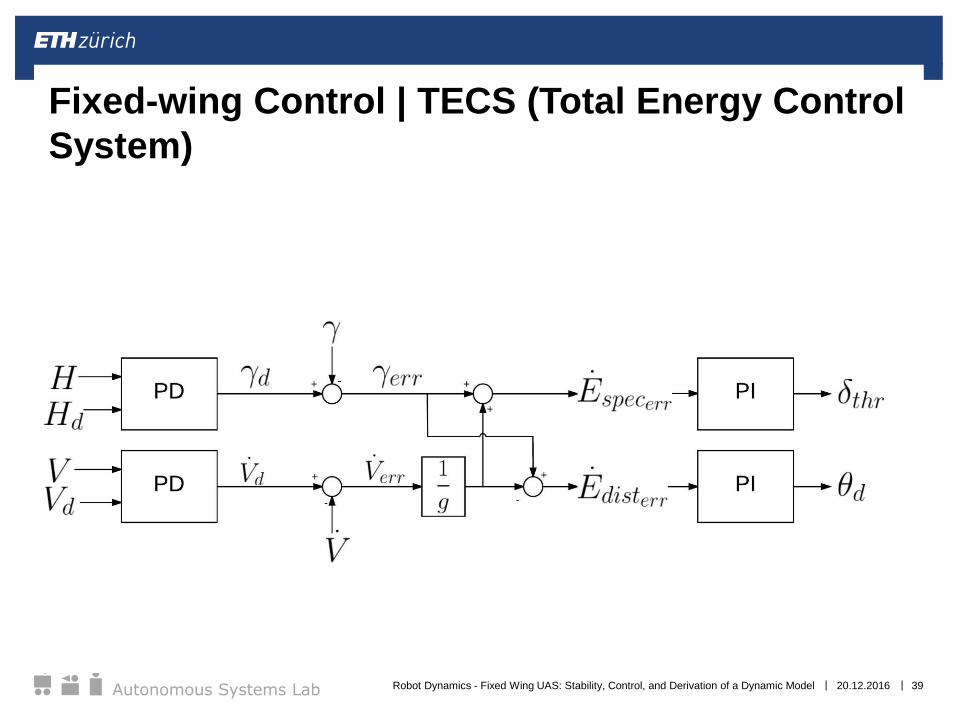
||Autonomous Systems Lab 20.12.2016 39
Fixed-wing Control | TECS (Total Energy Control
System)
Robot Dynamics - Fixed Wing UAS: Stability, Control, and Derivation of a Dynamic Model
||Autonomous Systems Lab
In lower-level loops, dynamics are modeled from
actuators→attitude/airspeed
Note that aside from computaitonal costs, these dynamics are
challenging to globally identify in a nonlinear, high fidelity form.
Thus linearizations are often made.
Higher-level loops often model the aircraft in a three-
degrees-of-freedom (3DoF) sense, mapping
attitude/airspeed→position
Modeling of high-level dynamics does not require identification, as
typically only kinematics are used.
Fixed-wing Control | Note the model abstraction
20.12.2016 40Robot Dynamics - Fixed Wing UAS: Stability, Control, and Derivation of a Dynamic Model
||Autonomous Systems Lab
What could be on the exam?
20.12.2016 41
Basic aerodynamic concepts / definitions
Aircraft reference frames
Model derivation (decoupling)
Performance analysis (calculations)
Stability criteria
Model abstractions for control (high- vs. low-level)
Robot Dynamics - Fixed Wing UAS: Stability, Control, and Derivation of a Dynamic Model

||Autonomous Systems Lab
See you tomorrow for the exercise!
20.12.2016 42
Next week – Fixed-wing case studies!
Robot Dynamics - Fixed Wing UAS: Stability, Control, and Derivation of a Dynamic Model
Recommended