Finite Element Analyses in Geotechnical Engineering – Some Thoughts
and Recommendations concerning Quality Assurance
Prof. Dr.-Ing. habil. Peter-Andreas von Wolffersdorff
Dr.-Ing. Thomas Meier BAUGRUND DRESDEN Ingenieurgesellschaft
1 Introduction
Since the 1980s numerical calculation procedures, such as the Finite Element Method
(FEM) or the Finite Differences Method (FDM) rank among the essential tools in engi-
neering practice. Modern and user-friendly computer codes make it easy to generate FE
models, to perform the respective FE calculations and to post-process the results. Thus,
numerical methods in Geotechnical engineering are indispensible today, and have found
a wide distribution.
With the aid of the FEM or other numerical methods it is now possible to yield realistic
solutions to complex geotechnical problems, where the soil-structure-interaction plays a
key role and conventional soil or rock mechanical approaches cannot be applied. The
application of modern FE and FD software packages comprises the following fields of
geotechnical engineering:
• Calculation of stress and strain fields
• Calculation of ground water flow
• Stability calculations
• Design of geotechnical structures
Especially for the calculation of stresses and strains of geotechnical structures and the
adjacent soil numerical methods have proved to be useful tools. Figure 1 depicts a de-

- 2 -
formed FE mesh of a retaining wall supported by three layers of anchors1 of the final
excavation level and the respective deviatoric stress field.
Figure 1 Diaphragm wall with 3 layers of anchors: deformed FE
mesh (left) and deviatoric stress field (right)
Seepage analyses in conjunction with stability analyses for water engineering structures
by means of the FEM represent another important field of application. Though soil-
water coupled stress-strain analyses are possible now, their practical application in prac-
tice is still limited.
Figure 2 Seepage flow analysis of a dam: Seepage flow line and
equi-potential lines, results from a steady-state phreatic sur-face seepage analysis
Figure 2 depicts exemplarily the result of a FE steady-state seepage flow analysis of a
dam.
In the course of stability analyses by means of the FEM using a simple elasto-plastic
constitutive model with a Mohr-Coulomb failure criterion, the parameters governing
shear strength, i.e. tan ϕ‘ und c’ are gradually reduced until a limit state in the model is
reached (phi-c-reduction). Especially complex failure mechanisms together with the
1 The given example was used for comprehensive comparative analyses in the framework of benchmark
test no. 3 of the Committee on Numerical Methods in Geotechnics of the German Geotechnical Society
(Schweiger 2000).
- 3 -
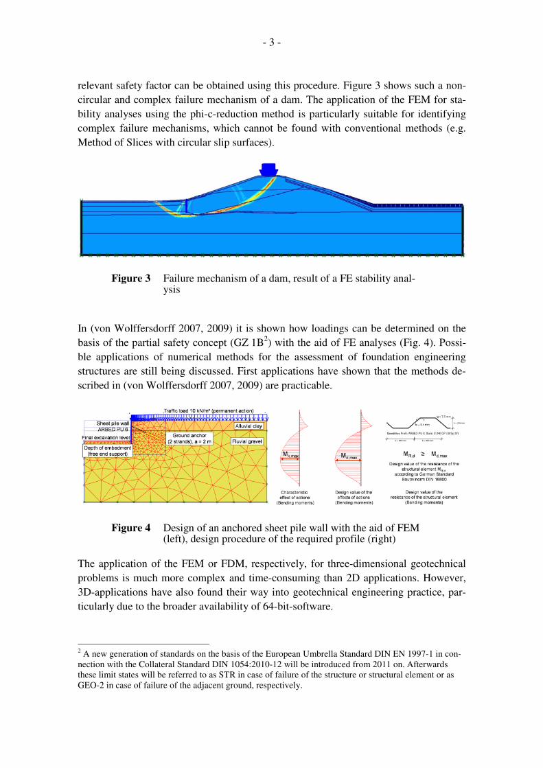
relevant safety factor can be obtained using this procedure. Figure 3 shows such a non-
circular and complex failure mechanism of a dam. The application of the FEM for sta-
bility analyses using the phi-c-reduction method is particularly suitable for identifying
complex failure mechanisms, which cannot be found with conventional methods (e.g.
Method of Slices with circular slip surfaces).
Figure 3 Failure mechanism of a dam, result of a FE stability anal-ysis
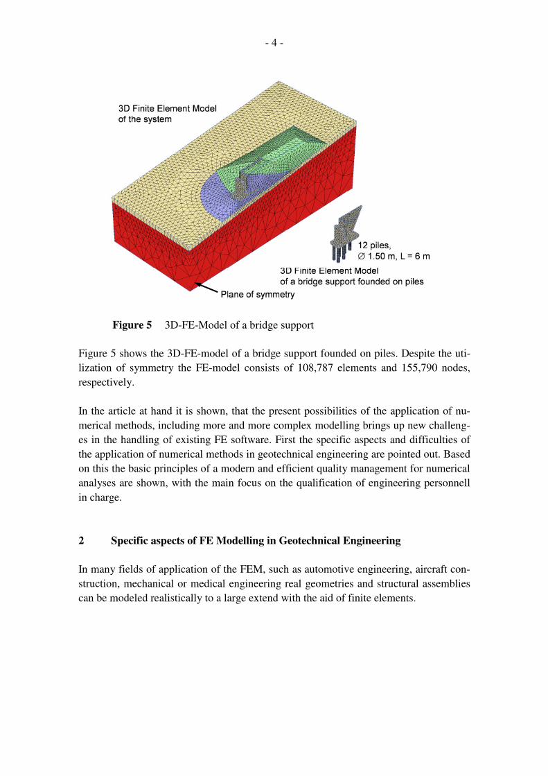
In (von Wolffersdorff 2007, 2009) it is shown how loadings can be determined on the
basis of the partial safety concept (GZ 1B2) with the aid of FE analyses (Fig. 4). Possi-
ble applications of numerical methods for the assessment of foundation engineering
structures are still being discussed. First applications have shown that the methods de-
scribed in (von Wolffersdorff 2007, 2009) are practicable.
Figure 4 Design of an anchored sheet pile wall with the aid of FEM (left), design procedure of the required profile (right)
The application of the FEM or FDM, respectively, for three-dimensional geotechnical
problems is much more complex and time-consuming than 2D applications. However,
3D-applications have also found their way into geotechnical engineering practice, par-
ticularly due to the broader availability of 64-bit-software.
2 A new generation of standards on the basis of the European Umbrella Standard DIN EN 1997-1 in con-
nection with the Collateral Standard DIN 1054:2010-12 will be introduced from 2011 on. Afterwards
these limit states will be referred to as STR in case of failure of the structure or structural element or as
GEO-2 in case of failure of the adjacent ground, respectively.
- 4 -
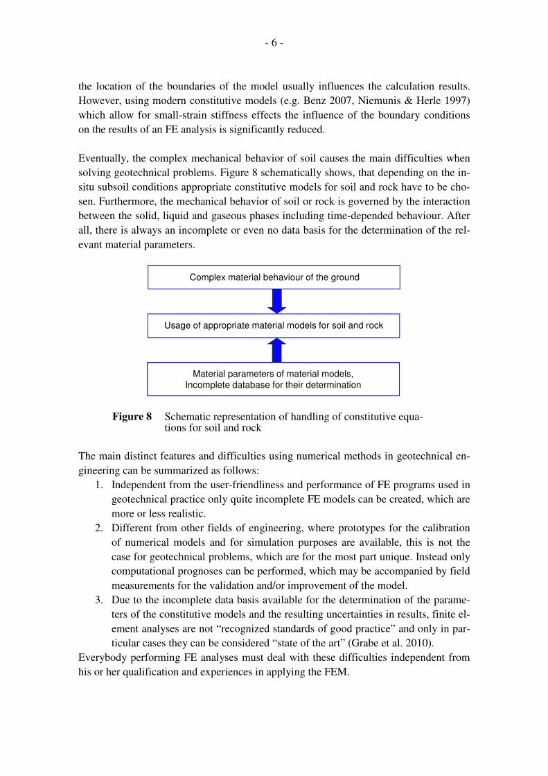
Figure 5 3D-FE-Model of a bridge support
Figure 5 shows the 3D-FE-model of a bridge support founded on piles. Despite the uti-
lization of symmetry the FE-model consists of 108,787 elements and 155,790 nodes,
respectively.
In the article at hand it is shown, that the present possibilities of the application of nu-
merical methods, including more and more complex modelling brings up new challeng-
es in the handling of existing FE software. First the specific aspects and difficulties of
the application of numerical methods in geotechnical engineering are pointed out. Based
on this the basic principles of a modern and efficient quality management for numerical
analyses are shown, with the main focus on the qualification of engineering personnell
in charge.
2 Specific aspects of FE Modelling in Geotechnical Engineering
In many fields of application of the FEM, such as automotive engineering, aircraft con-
struction, mechanical or medical engineering real geometries and structural assemblies
can be modeled realistically to a large extend with the aid of finite elements.

- 5 -
Figure 6 Stages of modelling: from reality to FE
In geotechnical engineering the procedure of modeling starting from the real subsoil,
preparation of a ground model and the development of a corresponding numerical mod-
el, is much more complex and demands a much higher degree of abstraction. Figure 6
depicts exemplarily the three stages of modeling of an open cut. Even in the presence of
a comprehensive in-situ soil investigation generally only partial information about the
geometry of the stratigraphic sequence, the phreatic conditions and the soil mechanical
properties of the soil layers is available and thus only relatively incomplete models of
the subsoil can be created compared to other engineering disciplines.
Figure 7 Determination of model boundaries: surrounding, real subsoil (left), FE model of the pile foundation of the arch of the bridge (right)
A further difficulty in geotechnical engineering using the FEM or FDM, results from
the fact that the model boundaries domain to be analysed has to be determined (Fig. 7).
Although, e.g. in (Meißner et al. 2002, von Wolffersdorff & Schweiger 2008) recom-
mendations for the choice of the size of the domain are given it must be considered that
- 6 -
the location of the boundaries of the model usually influences the calculation results.
However, using modern constitutive models (e.g. Benz 2007, Niemunis & Herle 1997)
which allow for small-strain stiffness effects the influence of the boundary conditions
on the results of an FE analysis is significantly reduced.
Eventually, the complex mechanical behavior of soil causes the main difficulties when
solving geotechnical problems. Figure 8 schematically shows, that depending on the in-
situ subsoil conditions appropriate constitutive models for soil and rock have to be cho-
sen. Furthermore, the mechanical behavior of soil or rock is governed by the interaction
between the solid, liquid and gaseous phases including time-depended behaviour. After
all, there is always an incomplete or even no data basis for the determination of the rel-
evant material parameters.
Figure 8 Schematic representation of handling of constitutive equa-tions for soil and rock
The main distinct features and difficulties using numerical methods in geotechnical en-
gineering can be summarized as follows:
1. Independent from the user-friendliness and performance of FE programs used in
geotechnical practice only quite incomplete FE models can be created, which are
more or less realistic.
2. Different from other fields of engineering, where prototypes for the calibration
of numerical models and for simulation purposes are available, this is not the
case for geotechnical problems, which are for the most part unique. Instead only
computational prognoses can be performed, which may be accompanied by field
measurements for the validation and/or improvement of the model.
3. Due to the incomplete data basis available for the determination of the parame-
ters of the constitutive models and the resulting uncertainties in results, finite el-
ement analyses are not “recognized standards of good practice” and only in par-
ticular cases they can be considered “state of the art” (Grabe et al. 2010).
Everybody performing FE analyses must deal with these difficulties independent from
his or her qualification and experiences in applying the FEM.
Complex material behaviour of the ground
Usage of appropriate material models for soil and rock
Material parameters of material models,
Incomplete database for their determination
- 7 -
3 Current Problems of Quality Management of Geotechnical Numerical
Analyses
The user-friendly graphical interfaces of many FE programs make it possible for unex-
perienced, insufficiently qualified users to create FE models, perform FE analyses and
to evaluate the results.
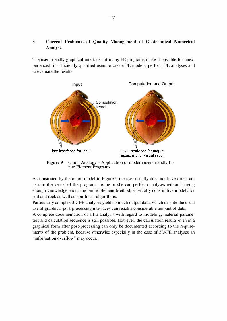
Figure 9 Onion Analogy – Application of modern user-friendly Fi-
nite Element Programs
As illustrated by the onion model in Figure 9 the user usually does not have direct ac-
cess to the kernel of the program, i.e. he or she can perform analyses without having
enough knowledge about the Finite Element Method, especially constitutive models for
soil and rock as well as non-linear algorithms.
Particularly complex 3D-FE analyses yield so much output data, which despite the usual
use of graphical post-processing interfaces can reach a considerable amount of data.
A complete documentation of a FE analysis with regard to modeling, material parame-
ters and calculation sequence is still possible. However, the calculation results even in a
graphical form after post-processing can only be documented according to the require-
ments of the problem, because otherwise especially in the case of 3D-FE analyses an
“information overflow” may occur.

- 8 -
Figure 10 Conventional flow of a project with subsequent control
The problems mentioned here cannot be overcome by a conventional internal quality
management, i.e. double and triple checking and careful third party control. It has to be
stated, that strictly speaking complex computations, such as 3D-FE analyses, are no
longer checkable. I.e. the conventional project processing (Fig. 10) with the planer per-
forming the FE analysis and documenting the results both together with an internal
quality management and with a subsequent check by a generally accepted geotechnical
expert is no longer adequate.
4 Recommendations for an Improved Quality Management of Numerical
Analyses in Geotechnical Engineering
In order to efficiently and reliably implement complex numerical analyses into geotech-
nical projects, it is necessary that all parties involved, e.g. client, authorized expert, au-
thorizing agency as well as designer and computational engineer work together prior
and during the project execution phase. Especially the authorized expert will have to be
embedded into the project prior to carrying out numerical analyses.
Database of project(Modelling and
design assumptions,
specifications)
Performing analyses and
documentation of results
Designer
Internal quality management
Checking calculations or
results
Authorized expert
Process of project management

- 9 -
Figure 11 New flow of a project with accompanying checking and plausibility control
Figure 11 depicts a proposal of an improved project flow. Contrary to the old project
flow (cf. Fig. 10) the authorized expert is already involved in the phase of the devel-
opement of the database of a project for coordination purposes, where essential model-
ling and calculation assumptions are defined. Because of time and financial reasons, in
general it will not be possible for the authorized expert to perform comparative numeri-
cal calculations in the framework of his subsequent checking and not in all cases it will
be possible to perform conventional calculations or estimations, thus it will be also nec-
essary to consult him for defining the extend of the documentation of the results.
The subsequent checking can then be limited to plausibility checks mainly, since com-
plex numerical analyses cannot be checked in detail afterwards.
Precondition for a successful realisation of the new project flow is, that the modelling
engineer or the team of engineers has above-average qualifications in the field of nu-
merical methods and geotechnical engineering. Most modelling engineers in geotech-
nical practice are not embedded in continuously working teams or departments, with
sometimes self-organised advanced training like e.g. in mechanical engineering, car or
aviation industry. Often they work alone. Skills acquired at university are generally suf-
ficient for a confident mastery of the user interfaces and the handling of the programs
on the level of the manuals, but they are not sufficient for a competent application of
complex FE programs and for competent judgement and interpretation of the results.
Hence it is recommended to develop and introduce a qualified advanced training system
with a standardised requirement profile and, if applicable, with a certified degree.
Database of project
(Modelling and
design assumptions,
specifications)
Performing analyses and
documentation of
results
Designer
Internal quality management
Plausibility check of
calculations and
results
Authorized expert
Checking and
coordination
Authorized expert,
client and others
Process of project management
Control and
coordination
Authorized expert
- 10 -
In this context knowledge in the following fields is essential:
• Modern theoretical soil mechanics
• Continuum mechanics
• Theory of Finite Elements
• Numerical mathematics
• Constitutive modelling of soil and rock
Beyond that, for bigger geotechnical companies it is recommended to form teams of
modelling engineers, who can further develop through their team work and communica-
tion.
References
Benz. Th. (2007)
Small-Strain Stiffness of Soils and its Numerical Consequences, Universität
Stuttgart, Mitteilungen des Institutes für Geotechnik Nr. 55, Publisher P.A. Ver-
meer, 2007
Grabe J., Hettler, A. Drewsen G.-F (2011)
Zwischenruf: Entspricht die Anwendung der FEM in der Geotechnik dem Stand
der Technik, Vorträge der Baugrundtagung 2010 in München, Hrsg. Deutsche
Gesellschaft für Geotechnik (DGGT), pp. 241 – 246
Meißner, H. et al. (2002)
Baugruben – Empfehlungen des Arbeitskreises 1.6 „Numerik in der Geotechnik“,
Abschnitt 3, Geotechnik 25(2002)1, pp. 44 – 50
Niemunis, A., Herle, I. (1997)
Hypoplastic model for cohesionless soils with elastic strain range. Mechanics of
Cohesive-Frictional Materials, 2(1997)1, pp. 279 – 299
Schweiger, H. F. (2000)
Ergebnisse des Berechnungsbeispiels Nr. 3 „3-fach verankerte Baugrube“ (Ge-
genüberstellung der eingesandten Berechnungsergebnisse), Workshop Verfor-
mungsprognose für Tiefe Baugruben, AK 1.6 „Numerik in der Geotechnik“,
Deutsche Gesellschaft für Geotechnik, 2000, pp. 1 – 67

- 11 -
von Wolffersdorff, P.-A., Schweiger, H. F. (2008)
Numerische Verfahren in der Geotechnik, Kap. 1.9, Grundbautaschenbuch Teil 1,
7th run, Publisher WITT, K.J, Ernst & Sohn Verlag für Architektur und techni-
sche Wissenschaften, 2008, pp. 501 – 557
von Wolffersdorff, P.-A. (2007)
Wie soll die FEM in geotechnische Bemessungsvorschriften einfließen? Work-
shop Bemessen mit Finite-Elemente-Methode, Technische Universität Hamburg-
Harburg, Veröffentl. Inst. Geotechnik Nr. 14, Publisher J. Grabe, pp. 133 – 144,
Hamburg 2007
von Wolffersdorff, P.-A. (2009)
Wie sind zukünftig moderne numerische Berechnungsverfahren in das Sicher-
heitskonzept der neuen Normengeneration eingebettet?, 4. Symposium
UMWELTGEOTECHNIK & 5. Freiberger GEOTECHNIK-Kolloquium 2009,
CiF e.V. publication 7, pp. 50 – 65
Recommended


![[PPT]Finite Element Method in Geotechnical Engineeringceae.colorado.edu/~sture/plaxis/slides/FEM in Geotech... · Web viewFinite Element Method in Geotechnical Engineering Short Course](https://img.pdfslide.us/doc/110x75/5ae742467f8b9ae1578ec31f/pptfinite-element-method-in-geotechnical-stureplaxisslidesfem-in-geotechweb.jpg)