Flow Control Valves
F68 www.stauff.com
Throttle and Shut-Off Valve � Type DV (In-Line Assembly)
Dimensions / Technical Data / Order Codes
Characteristics
Throttle and shut-off the flow of liquid media in both directions
Features � Designed for in-line assembly with female BSP, NPT and SAE threaded connections
� Panel mounting nuts available on request � Graduated turning knob and coded spindle to accurately control flow
� Set-screw located on side of turning knob to lock valve in position
Media Compatibility � Suitable for hydraulic fluids
Please consult STAUFF before using with other media.
Materials � Body and spindle made of Steel (1.0715), zinc/iron-plated (Fe/Zn Fe Co 8 C) and free of hexavalent chromium CrVI (standard option); Stainless Steel (1.4571) version available
� Turning knob made of Polyamide (PA) � O-rings made of NBR (Buna-N®); FPM (Viton®) and EPDM sealed version available
Consult STAUFF for alternative materials.
Technical Data � Maximum working pressure: 350 bar / 5000 PSI (for all sizes)
� Operating temperature range: -20 °C ... +100 °C / -4 °F ... +212 °F
Please see page F76 for detailed flow characteristics.
B A
Type + Thread Dimensions (mm/in) WeightNominal Size Options G1 G2 H1 H2 H3 B1 ØD1 ØD2 S (Max.) L1 L2 (kg/lbs)
DV-06G1/8 BSP 1/8 NPT
PG 764 59 18 16 24 13 3 38 19 0,12
2.52 2.32 .71 .63 .94 .51 .12 1.50 .75 .26
DV-08G1/4 BSP 1/4 NPT 7/16–20 UNF (1/4" SAE)
PG 1183,5 77,5 27 25 29 19 7 48 24 0,25
3.29 3.05 1.06 .98 1.14 .75 .28 1.89 .94 .55
DV-10G3/8 BSP 3/8 NPT 9/16–18 UNF (3/4" SAE)
PG 1190 83 32 30 29 19 7 58 29 0,40
3.54 3.27 1.26 1.18 1.14 .75 .28 2.28 1.14 .88
DV-12G1/2 BSP 1/2 NPT 3/4–16 UNF (1/2" SAE)
PG 11109,5 99,5 38 35 38 23 7 68 34 0,60
4.31 3.92 1.50 1.38 1.50 .91 .28 2.68 1.34 1.32
DV-16G3/4 BSP 3/4 NPT1-1/16–12 UN (3/4" SAE)
PG 16128,5 118,5 48 45 38 23 7 78 39 1,10
5.06 4.67 1.89 1.77 1.50 .91 .28 3.07 1.54 2.43
DV-20G1 BSP 1 NPT1-5/16–12 UN (1" SAE)
PG 16159 146 55 50 49 38 10 108 54 2,40
6.26 5.75 2.17 1.97 1.93 1.50 .39 4.25 2.13 5.29
DV-25G1-1/4 BSP 1-1/4 NPT1-5/8–12 UN (1-1/4" SAE)
PG 29169 156 65 60 49 38 10 108 54 2,80
6.65 6.14 2.56 2.36 1.93 1.50 .39 4.25 2.13 6.17
DV-30G1-1/2 BSP 1-1/2 NPT1-7/8–12 UN (1-1/2" SAE)
PG 29175 166 75 70 49 38 10 108 54 3,50
6.89 6.54 2.95 2.76 1.93 1.50 .39 4.25 2.13 7.72
DV-40G2 BSP 2 NPT2-1/2–12 UN (2" SAE)
PG 29199 186 95 90 49 38 10 120 60 6,30
7.83 7.32 3.74 3.54 1.93 1.50 .39 4.72 2.36 13.89
Dimensions
DV - 25 - P - B - PM - SS
Order Codes
a Type Throttle and Shut-Off Valve (In-Line Assembly) DV
b Nominal Size DN
c Sealing Material NBR (Buna-N®) (standard option) P FPM (Viton®) V EPDM E
06 08 10 12 16 20 25 30 40
d Connection Female BSP threads (ISO 228) B Female NPT threads (ANSI B1.20.1) N Female UN/UNF thread (SAE J514) S
e Panel Mounting Nut Without panel mounting nut (standard option) - With panel mounting nut PM
f Body / Spindle Material Steel (standard option) - Stainless Steel SS
ø D2 Sm
ax
G1
L 2
L1
G1
8 9 0 1 2
B1
G2
H2
(clo
sed)
H1
(ope
n)
øD1
H3
Ventile BM 2011-02-29.indd 68 04.03.2011 18:27:15

Valv
esF
Flow Control Valves
www.stauff.com F69
Dimensions / Technical Data / Order Codes
Flow Control Valve � Type DRV (In-Line Assembly)
B A
Characteristics
Throttle and shut-off the flow of liquid media in direction A-B (free flow in reverse direction)
Features � Designed for in-line assembly with female BSP, NPT and SAE threaded connections
� Panel mounting nuts available on request � Graduated turning knob and coded spindle to accurately control flow
� Set-screw located on side of turning knob to lock valve in position
Media Compatibility � Suitable for hydraulic fluids
Please consult STAUFF before using with other media.
Materials � Body and spindle made of Steel (1.0715), zinc/iron-plated (Fe/Zn Fe Co 8 C) and free of hexavalent chromium CrVI (standard option); Stainless Steel (1.4571) version available
� Turning knob made of Polyamide (PA) � O-rings made of NBR (Buna-N®); FPM (Viton®) and EPDM sealed version available
Consult STAUFF for alternative materials.
Technical Data � Opening pressure: 0,5 bar / 7 PSI (4,5 bar / 65 PSI available on request)
� Maximum working pressure: 350 bar / 5000 PSI (for all sizes)
� Operating temperature range: -20 °C ... +100 °C / -4 °F ... +212 °F
Please see page F76 for detailed flow characteristics.
Type + Thread Dimensions (mm/in) WeightNominal Size Options G1 G2 H1 H2 H3 B1 ØD1 ØD2 S (Max.) L1 L2 (kg/lbs)
DRV-06G1/8 BSP 1/8 NPT
PG 764 59 18 16 24 13 3 45 26 0,10
2.52 2.32 .71 .63 .94 .51 .12 1.77 1.02 .22
DRV-08G1/4 BSP 1/4 NPT 7/16–20 UNF (1/4" SAE)
PG 1183,5 77,5 27 25 29 19 7 55 34 0,30
3.29 3.05 1.06 .98 1.14 .75 .28 2.17 1.32 .66
DRV-10G3/8 BSP 3/8 NPT 9/16–18 UNF (3/4" SAE)
PG 1190 83 32 30 29 19 7 65 41 0,45
3.54 3.27 1.26 1.18 1.14 .75 .28 2.56 1.61 .99
DRV-12G1/2 BSP 1/2 NPT 3/4–16 UNF (1/2" SAE)
PG 11109,5 99,5 38 35 38 23 7 73 44 0,70
4.31 3.92 1.50 1.38 1.50 .91 .28 2.87 1.73 1.54
DRV-16G3/4 BSP 3/4 NPT1-1/16–12 UN (3/4" SAE)
PG 16128,5 118,5 48 45 38 23 7 88 57 1,26
5.06 4.67 1.89 1.77 1.50 .91 .28 3.46 2.24 2.78
DRV-20G1 BSP 1 NPT1-5/16–12 UN (1" SAE)
PG 16159 146 55 50 49 38 10 127 77 2,60
6.26 5.75 2.17 1.97 1.93 1.50 .39 5.00 3.03 5.73
DRV-25G1-1/4 BSP 1-1/4 NPT1-5/8–12 UN (1-1/4" SAE)
PG 29169 156 65 60 49 38 10 143 93 3,70
6.65 6.14 2.56 2.36 1.93 1.50 .39 5.63 3.66 8.16
DRV-30G1-1/2 BSP 1-1/2 NPT1-7/8–12 UN (1-1/2" SAE)
PG 29175 166 75 70 49 38 10 143 91 4,76
6.89 6.54 2.95 2.76 1.93 1.50 .39 5.63 3.58 10.49
DRV-40G2 BSP 2 NPT2-1/2–12 UN (2" SAE)
PG 29199 186 95 90 49 38 10 165 111 8,52
7.83 7.32 3.74 3.54 1.93 1.50 .39 6.50 4.37 18.78
Dimensions
DRV - 25 - P - B - PM - SS
Order Codes
a Type Flow Control Valve (In-Line Assembly) DRV
b Nominal Size DN
c Sealing Material NBR (Buna-N®) (standard option) P FPM (Viton®) V EPDM E
06 08 10 12 16 20 25 30 40
d Connection Female BSP threads (ISO 228) B Female NPT threads (ANSI B1.20.1) N Female UN/UNF thread (SAE J514) S
e Panel Mounting Nut Without panel mounting nut (standard option) - With panel mounting nut PM
f Body / Spindle Material Steel (standard option) - Stainless Steel SS
L 1
L 2
G1
Sm
ax
ø D2
G1
8 9 0 1 2
B1
G2
H2
(clo
sed)
H1
(ope
n)
øD1
H3
Ventile BM 2011-02-29.indd 69 04.03.2011 18:27:20

Flow Control Valves
F70 www.stauff.com
Throttle and Shut-Off Valve � Type DVP (Manifold Assembly)
Dimensions / Technical Data / Order Codes
Characteristics
Throttle and shut-off the flow of liquid media in both directions
Features � Designed for manifold mounting � Panel mounting nuts available on request � Graduated turning knob and coded spindle to accurately control flow
� Set-screw located on side of turning knob to lock valve in position
Media Compatibility � Suitable for hydraulic fluids
Please consult STAUFF before using with other media.
Materials � Body and spindle made of Steel (1.0715), zinc/iron-plated (Fe/Zn Fe Co 8 C) and free of hexavalent chromium CrVI (standard option); Stainless Steel (1.4571) version available
� Turning knob made of Polyamide (PA) � O-rings made of FPM (Viton®); NBR (Buna-N®) and EPDM sealed version available
Consult STAUFF for alternative materials.
Technical Data � Maximum working pressure: 350 bar / 5000 PSI (for all sizes)
� Operating temperature range: -20 °C ... +100 °C / -4 °F ... +212 °F
Please see page F76 for detailed flow characteristics.
Recommended Bolts / Tightening Torques � Socket cap screws according to ISO 4762 or ANSI / ASME B18.3 recommended for installation (not included in delivery):
DVP-06 M6 x 20 - 8.8 (9 N·m)
1/4–20 UNC x 3/4 - Gr. 5 (10 ft·lb)
DVP-08 M6 x 25 - 8.8 (9 N·m)
1/4–20 UNC x 1 - Gr. 5 (10 ft·lb)
DVP-10 M6 x 30 - 10.9 (12 N·m)
1/4–20 UNC x 1-1/4 - Gr. 8 (12 ft·lb)
DVP-12 M6 x 30 - 12.9 (15 N·m)
1/4–20 UNC x 1-1/4 - Gr. 10 (14 ft·lb)
DVP-16 M8 x 35 - 10.9 (30 N·m)
5/16–18 UNC x 1-1/2 - Gr. 8 (24 ft·lb)
DVP-20 M8 x 50 - 12.9 (35 N·m)
5/16–18 UNC x 2 - Gr. 10 (29 ft·lb)
DVP-25 M10 x 50 - 12.9 (70 N·m)
3/8–16 UNC x 2 - Gr. 10 (58 ft·lb)
DVP-30 M12 x 60 - 10.9 (100 N·m)
7/16–14 UNC x 2-1/2 - Gr. 8 (63 ft·lb)
B A
Type + Dimensions (mm/in) WeightNom. Size ØD1 ØD3 ØD4 ØD5 ØD6 L1 L3 L4 L5 L6 L7 B1 B2 T1 H1 H2 H3 O-ring (kg/lbs)
DVP-0624 6,5 10,5 5 9,8 35 19 8 9,5 16 41,5 28,5 6,8 64 59 16
6,35 x 1,78
0,20
.94 .26 .41 .20 .39 1.38 .75 .31 .37 .63 1.63 1.12 .27 2.52 2.32 .63 .44
DVP-0829 6,5 10,5 7 12,4 47,5 35 6,5 11 25,5 46 33,5 6,8 79 72 20
8,5 x 20,40
1.14 .26 .41 .28 .49 1.87 1.38 .26 .43 1.00 1.81 1.32 .27 3.11 2.83 .79 .88
DVP-1029 6,5 10,5 10 15,7 51 33,5 8,5 12,7 25,5 51 38 6,8 84 78 25
12 x 20,60
1.14 .26 .41 .39 .62 2.01 1.32 .33 .50 1.00 2.01 1.50 .27 3.31 3.07 .98 1.32
DVP-1238 6,5 10,5 13 18,7 75 38 18,5 22,5 30 57,5 44,5 6,8 100 89 25
15 x 21,00
1.50 .26 .41 .51 .74 2.95 1.50 .73 .89 1.18 2.26 1.75 .27 3.94 3.50 .98 2.20
DVP-1638 8,5 13,5 17 23,9 93,5 76 38 8,5 19,5 54 70 54 9 113 103 30
19 x 2,51,50
1.50 .33 .53 .67 .94 3.68 2.99 1.50 .33 .77 2.13 2.76 2.13 .35 4.45 4.06 1.18 3.31
DVP-2049 8,5 13,5 22 30,5 111 95 47,5 8 27 57 76,5 60 9 154 142 45
25 x 33,40
1.93 .33 .53 .87 1.20 4.37 3.74 1.87 .31 1.06 2.24 3.01 2.36 .35 6.06 5.59 1.77 7.50
DVP-2549 10,5 16,5 28,5 37,5 143 120 60 11 32 79,5 100 76 11 154 142 45
32 x 35,15
1.93 .41 .65 1.12 1.48 5.63 4.72 2.36 .43 1.26 3.13 3.94 2.99 .43 6.06 5.59 1.77 11.35
DVP-3049 13 19 35 43,5 171 143 71,5 15 39 95 115 92 13 159 147 50
38 x 37,50
1.93 .51 .75 1.38 1.71 6.73 5.63 2.81 .59 1.54 3.74 4.53 3.62 .51 6.26 5.79 1.97 16.53
Dimensions
DVP - 25 - P - PM - SS
Order Codes
a Type Throttle and Shut-Off Valve (Manifold Assembly) DVP
b Nominal Size DN
c Sealing Material FPM (Viton®) (standard option) V NBR (Buna-N®) P EPDM E
06 08 10 12 16 20 25 30
d Panel Mounting Nut Without panel mounting nut (standard option) - With panel mounting nut PM
e Body / Spindle Material Steel (standard option) - Stainless Steel SS
B2
B1
inc lusive of O-rings
ø D1
H2
(clo
sed)
H1
(open)
H3
T1
Symbol
D5
D3
D4
L1
L3
L4L5
D6
L6 L7
B A
B2
B1
inc lusive of O-rings
ø D1
H2
(clo
sed)
H1
(open)
H3
T1
Symbol
D5
D3
D4
L1
L3
L4L5
D6
L6 L7
B A
For panel mounting, please see dimensions G2, D2 and S (Max.) on page F68.
O-rings included in delivery
Ventile BM 2011-02-29.indd 70 04.03.2011 18:27:23

Valv
esF
DRVP - 25 - P - PM - SS
Flow Control Valves
www.stauff.com F71
Dimensions / Technical Data / Order Codes
Flow Control Valve � Type DRVP (Manifold Assembly)
B A
Characteristics
Throttle and shut-off the flow of liquid media in direction A-B (free flow in reverse direction)
Features � Designed for manifold mounting � Panel mounting nuts available on request � Graduated turning knob and coded spindle to accurately control flow
� Set-screw located on side of turning knob to lock valve in position
Media Compatibility � Suitable for hydraulic fluids
Please consult STAUFF before using with other media.
Materials � Body and spindle made of Steel (1.0715), zinc/iron-plated (Fe/Zn Fe Co 8 C) and free of hexavalent chromium CrVI (standard option); Stainless Steel (1.4571) version available
� Turning knob made of Polyamide (PA) � O-rings made of FPM (Viton®); NBR (Buna-N®) and EPDM sealed version available
Consult STAUFF for alternative materials.
Technical Data � Opening pressure: 0,5 bar / 7 PSI (4,5 bar / 65 PSI available on request)
� Maximum working pressure: 350 bar / 5000 PSI (for all sizes)
� Operating temperature range: -20 °C ... +100 °C / -4 °F ... +212 °F
Please see page F76 for detailed flow characteristics.
Recommended Bolts / Tightening Torques � Socket cap screws according to ISO 4762 or ANSI / ASME B18.3 recommended for installation (not included in delivery):
DRVP-06 M6 x 20 - 8.8 (9 N·m)
1/4–20 UNC x 3/4 - Gr. 5 (10 ft·lb)
DRVP-08 M6 x 25 - 8.8 (9 N·m)
1/4–20 UNC x 1 - Gr. 5 (10 ft·lb)
DRVP-10 M6 x 30 - 10.9 (12 N·m)
1/4–20 UNC x 1-1/4 - Gr. 8 (12 ft·lb)DRVP-12 M6 x 35 - 12.9 (15 N·m) 1/4–20 UNC x 1-1/2 - Gr. 10 (14 ft·lb)DRVP-16 M8 x 50 - 10.9 (30 N·m) 5/16–18 UNC x 2 - Gr. 8 (24 ft·lb)DRVP-20 M8 x 55 - 12.9 (35 N·m) 5/16–18 UNC x 2-1/4 - Gr. 10 (29 ft·lb)DRVP-25 M10 x 60 - 12.9 (70 N·m) 3/8–16 UNC x 2-1/2 - Gr. 10 (58 ft·lb)DRVP-30 M12 x 85 - 10.9 (100 N·m) 7/16–14 x 3-1/2 - Gr. 8 (63 ft·lb)DRVP-40 M12 x 100 - 12.9 (130 N·m) 7/16–14 x 4 - Gr. 10 (70 ft·lb)
Dimensions
Order Codes
a Type Flow Control Valve (Manifold Assembly) DRVP
b Nominal Size DN
c Sealing Material FPM (Viton®) (standard option) V NBR (Buna-N®) P EPDM E
06 08 10 12 16 20 25 30 40
d Panel Mounting Nut Without panel mounting nut (standard option) - With panel mounting nut PM
e Body / Spindle Material Steel (standard option) - Stainless Steel SS
Symbol
D6
B2
B1
D5
D3
D4
L1
L3
L4L5
L6 L7
L8
inc lusive of O-rings
H2
(clo
sed
)
H1
(op
en)
H3
L9øD1
T1
B A
Symbol
D6
B2
B1
D5
D3
D4
L1
L3
L4L5
L6 L7
L8
inc lusive of O-rings
H2
(clo
sed
)
H1
(op
en)
H3
L9øD1
T1
B A
Type + Dimensions (mm/in) WeightNom. Size ØD1 ØD3 ØD4 ØD5 ØD6 L1 L3 L4 L5 L6 L7 L8 L9 B1 B2 T1 H1 H2 H3 O-ring (kg/lbs)
DRVP-0624 6,5 10,5 5 9,8 41,5 19 6,4 8 16 47 13,5 41,5 28,5 6,8 64 59 16 6,35 x
1,78
0,26
.94 .26 .41 .20 .39 1.63 .75 .25 .31 .63 1.85 .53 1.63 1.12 .27 2.52 2.32 .63 .57
DRVP-0829 6,5 10,5 7 12,4 63,5 35 14,2 18,7 25,5 70 31 46 33,5 6,8 79 72 20
8,5 x 20,50
1.14 .26 .41 .28 .49 2.50 1.38 .56 .74 1.00 2.76 1.22 1.81 1.32 .27 3.11 2.83 .79 1.10
DRVP-1029 6,5 10,5 10 15,7 70 33,5 18 22,0 25,5 75 29,5 51 38 6,8 84 78 25
12 x 20,80
1.14 .26 .41 .39 .62 2.76 1.32 .71 .87 1.00 2.95 1.16 2.01 1.50 .27 3.31 3.07 .98 1.76
DRVP-1238 6,5 10,5 13 18,7 80 38 21 25,0 30 86 36,5 57,5 44,5 6,8 107 96 32
15 x 21,20
1.50 .26 .41 .51 .74 3.15 1.50 .83 .98 1.18 3.39 1.44 2.26 1.75 .27 4.21 3.78 1.26 2.65
DRVP-1638 8,5 13,5 17 23,9 104 76 38 14 25,4 54 110 49 70 54 9 128 118 45
19 x 2,52,50
1.50 .33 .53 .67 .94 4.09 2.99 1.50 .55 1.00 2.13 4.33 1.93 2.76 2.13 .35 5.04 4.65 1.77 5.51
DRVP-2049 8,5 13,5 22 30,5 127 95 47,5 16 35 57 133 49 76,5 60 9 159 147 50
25 x 33,90
1.93 .33 .53 .87 1.20 5.00 3.74 1.87 .63 1.38 2.24 5.24 1.93 3.01 2.36 .35 6.26 5.79 1.97 8.60
DRVP-2549 10,5 16,5 28,5 37,5 165 120 60 15 35,6 79,5 171 77 100 76 11 164 152 55
32 x 36,70
1.93 .41 .65 1.12 1.48 6.50 4.72 2.36 .59 1.40 3.13 6.73 3.03 3.94 2.99 .43 6.46 5.98 2.17 14.77
DRVP-3049 13 19 35 43,5 186 143 71,5 15 38,8 95 192 85 115 92 13 184 172 75
38 x 311,00
1.93 .51 .75 1.38 1.71 7.32 5.63 2.81 .59 1.53 3.74 7.56 3.35 4.53 3.62 .51 7.24 6.77 2.95 24.25
DRVP-4049 13 19 47,5 57,5 192 133,5 67,5 16 41,5 89 197 64 140 111 13 209 197 100
52 x 318,80
1.93 .51 .75 1.87 2.26 7.56 5.25 2.66 .63 1.63 3.50 7.76 2.52 5.51 4.37 .51 8.23 7.76 3.94 41.45
For panel mounting, please see dimensions G2, D2 and S (Max.) on page F69.
O-rings included in delivery
Flow Control Valve � Type DRVP (Manifold Assembly)
Ventile BM 2011-02-29.indd 71 04.03.2011 18:27:28

Flow Control Valves
F72 www.stauff.com
Throttle and Shut-Off Valve � Type DVE (Cartridge Assembly)
Dimensions / Technical Data / Order Codes
Characteristics
Throttle and shut-off the flow of liquid media in both directions
Features � Designed for direct installation into hydraulic manifolds with male BSP threaded stud
� Graduated turning knob and coded spindle to accurately control flow
� Set-screw located on side of turning knob to lock valve in position
Media Compatibility � Suitable for hydraulic fluids
Please consult STAUFF before using with other media.
Materials � Body and spindle made of Steel (1.0715), zinc/iron-plated (Fe/Zn Fe Co 8 C) and free of hexavalent chromium CrVI (standard option); Stainless Steel (1.4571) version available
� Turning knob made of Polyamide (PA) � O-rings made of NBR (Buna-N®); FPM (Viton®) and EPDM sealed version available
Consult STAUFF for alternative materials.
Technical Data � Maximum working pressure: 350 bar / 5000 PSI (for all sizes)
� Operating temperature range: -20 °C ... +100 °C / -4 °F ... +212 °F
Please see page F76 for detailed flow characteristics.
B A
Type + Thread Dimensions (mm/in) WeightNom. Size Options G H1 H2 H3 H4 ØD1 ØD2 ØD3 ØD4 ØD5 ØD6 ØD7 ØD8 SW T2 T3 T4 T5 T6 (kg/lbs)
DVE-08 G1/2 BSP
47 41 28 12,0 29 32 24 14 14 5 5 5 27 1,9 14 17,5 15 29 0,15
1.85 1.61 1.08 .47 1.14 1.26 .94 .55 .55 .20 .20 .20 1.06 .07 .55 .69 .59 1.14 .33
DVE-10 G1/2 BSP
64 54 31 14,5 38 32 24 16 16 8 6 8 27 1,9 14 20,5 17 33 0,25
2.52 2.13 1.21 .57 1.50 1.26 .94 .63 .63 .31 .24 .31 1.06 .07 .55 .81 .67 1.30 .55
DVE-12 G3/4 BSP
65 55 40 17,5 38 37 30 19 19 10 8 10 32 1,9 21 29,0 24 43 0,50
2.56 2.17 1.57 .69 1.50 1.46 1.18 .75 .75 .39 .31 .39 1.26 .07 .83 1.14 .94 1.69 1.10
DVE-16 G1 BSP
65 55 44 21,1 38 47 36 27 27 12 8 12 41 1,9 21 30,0 24 47 0,70
2.56 2.17 1.71 .83 1.50 1.85 1.42 1.06 1.06 .47 .31 .47 1.61 .07 .83 1.18 .94 1.85 1.54
Dimensions
DVE - 16 - P - B - SS
Order Codes
d Connection Male BSP thread (ISO 228) B
e Body / Spindle Material Steel (standard option) - Stainless Steel SS
a Type Throttle and Shut-Off Valve (Cartridge Assembly) DVE
b Nominal Size DN
c Sealing Material NBR (Buna-N®) (standard option) P FPM (Viton®) V EPDM E
08 10 12 16
T3
T4
6.3
1.5
x 20
°1
T2+
0.1
øD8
3.2
øD6
T5
T6
øD4H8
G (ISO228)
øD3+0.1
øD2
3.2
Installation Details
G (ISO 228)
H2 (
clo
sed)
H1 (
open)
H4
H3
ø D1
SW
øD7
øD5
G
Dimensional drawings: All dimensions in mm only.
H2 (c
lose
d)
H1 (o
pen)
Ventile BM 2011-02-29.indd 72 04.03.2011 18:27:32

Valv
esF
Flow Control Valves
www.stauff.com F73
Dimensions / Technical Data / Order Codes
Characteristics
Throttle and shut-off the flow of liquid media in direction A-B (free flow in reverse direction)with pressure compensating feature via built-in compensating piston
Features � Designed for in-line assembly with female BSP, NPT and SAE threaded connections
� Panel mounting nuts available on request � Graduated turning knob to accurately control flow � Set-screw located on side of turning knob to lock valve in position
Media Compatibility � Suitable for hydraulic fluids
Please consult STAUFF before using with other media.
Materials � Body made of Steel, phosphated � Internal components made of Stainless Steel � Turning knob made of Aluminium � O-rings made of NBR (Buna-N®) � Anti-extrusion ring made of PTFE
Consult STAUFF for alternative materials.
Technical Data � Maximum working pressure: 210 bar / 3000 PSI (for all sizes)
� Operating temperature range: -20 °C ... +120 °C / -4 °F ... +248 °F
� Minimum filtration grade: 25 µm (absolute) to ensure the correct functioning, reduce wear and tear and increase the service life of the valve
Flow Characteristics
Dimensions
PNDRV - 12 - P - B - PM
Order Codes
d Connection Female BSP thread (ISO 228) B Female NPT thread (ANSI B1.20.1) N Female UN/UNF thread (SAE J514) S
e Panel Mounting Nut Without panel mounting nut (standard option) - With panel mounting nut PM
a Type Pressure Compensated Flow Control Valve (In-Line Assembly)
PNDRV
b Nominal Size DN
c Sealing Material NBR (Buna-N®) (standard option) P FPM (Viton®) V EPDM E
08 10 12 16
Type + Thread Dimensions (mm/in) WeightNominal Size Options G1 L1 L2 H1 H2 H3 H4 G2 (kg/lbs)
PNDRV-08
G1/4 BSP 1/4 NPT 7/16–20 UNF (1/4" SAE)
94 12,5 88,5 81,5 30 15
M20 x 1
0,58
3.70 .49 3.48 3.21 1.18 .59 .77
PNDRV-10
G3/8 BSP 3/8 NPT 9/16–18 UNF (3/4" SAE)
110,5 13 103 94,5 35 17
M25 x 1,5
0,94
4.35 .51 4.06 3.72 1.38 .67 2.09
PNDRV-12
G1/2 BSP
1/2 NPT 3/4–16 UNF (1/2" SAE)
137 15,5 122 112 45 18
M30 x 1,5*
1,83
5.39 .61 4.80 4.41 1.77 .71 4.07
PNDRV-16
3/4 NPT G3/4 BSP
1-1/16–12 UN (3/4" SAE)
163 17 150 138 55 24
M40 x 1,5
3,35
6.42 .67 5.91 5.43 2.17 .94 7.44
Pressure Compensated Flow Control Valve � Type PNDRV (In-Line Assembly)
B A
20
2
0
4
6
8
10-8 -10 -12 -16
�p
in b
ar
40 60 80 100 120 140 160 Q in l/min
5.3 10.6 15.8 21.1 26.4 31.7 37.0 42.2 Q in US GPM
29
58
87
116
145
�p
in P
SI
-8
-10
-12
-16
Q in l/m
in
Q in U
S G
PM
10
0
20
30
40
50
60
70
80
2.6
5.3
7.9
10.6
13.2
15.8
18.5
21.1
1 2 3 4 5 6 7 8 9
Pres
sure
Dro
pFl
ow
Flow
Handle Turns
* M25 x 1,5 for version with female UN/UNF thread (SAE J514)
Ventile BM 2011-02-29.indd 73 04.03.2011 18:27:34

Flow Control Valves
F74 www.stauff.com
Dimensions / Technical Data / Order Codes
Characteristics
Allows a single-directional flow only
Features � Designed for in-line assembly with female BSP, NPT and SAE threaded connections
� Metal-to-metal seat
Media Compatibility � Suitable for hydraulic fluids
Please consult STAUFF before using with other media.
Materials � Body made of Steel (1.0715), zinc/iron-plated (Fe/Zn Fe Co 8 C) and free of hexavalent chromium CrVI (standard option); Stainless Steel (1.4571) version available
Technical Data � Opening pressure: 0,5 bar / 7 PSI (4,5 bar / 65 PSI available on request)
� Maximum working pressure: 500 bar / 7250 PSI (depending on size)
� Operating temperature range: -20 °C ... +100 °C / -4 °F ... +212 °F
Please see page F76 for detailed flow characteristics.
B A
Symbol
Heavy-Duty Check Valve � Type RV (In-Line Assembly)
Dimensions
Type + Thread Options G1 Dimensions (mm/in) Working Pressure WeightNominal Size L1 B1 PN (bar/PSI) (kg/lbs)
RV-06G1/8 BSP 1/8 NPT
45 16 500 0,10
1.77 .63 7250 .22
RV-08G1/4 BSP 1/4 NPT 7/16–20 UNF (1/4" SAE)
55 25 500 0,20
2.17 .98 7250 .44
RV-10G3/8 BSP 3/8 NPT 9/16–18 UNF (3/4" SAE)
65 30 500 0,40
2.56 1.18 7250 .88
RV-12G1/2 BSP 1/2 NPT 3/4–16 UNF (1/2" SAE)
73 35 500 0,70
2.87 1.38 7250 1.54
RV-16G3/4 BSP 3/4 NPT1-1/16–12 UN (3/4" SAE)
88 45 500 1,20
3.46 1.77 7250 2.64
RV-20G1 BSP 1 NPT1-5/16–12 UN (1" SAE)
127 50 500 2,00
5.00 1.97 7250 4.40
RV-25G1-1/4 BSP 1-1/4 NPT1-5/8–12 UN (1-1/4" SAE)
143 60 400 3,30
5.63 2.36 5800 7.26
RV-30G1-1/2 BSP 1-1/2 NPT1-7/8–12 UN (1-1/2" SAE)
143 70 315 4,20
5.63 2.75 4500 9.24
RV-40G2 BSP 2 NPT2-1/2–12 UN (2" SAE)
165 90 315 7,20
6.49 3.54 4500 15.84
RV - 25 - 07 - B - SS
Order Codes
d Connection Female BSP thread (ISO 228) B Female NPT thread (ANSI B1.20.1) N Female UN/UNF thread (SAE J514) S
e Body Material Steel (standard option) - Stainless Steel SS
a Type Heavy-Duty Check Valve (In-Line Assembly) RV
b Nominal Size DN
c Opening Pressure 0,5 bar / 7 PSI (standard option) 07 4,5 bar / 65 PSI 65 Consult STAUFF for alternative opening pressures.
06 08 10 12 16 20 25 30 40
AB
G1
G1
L1 B1
Ventile BM 2011-02-29.indd 74 04.03.2011 18:27:36
Valv
esF
Flow Control Valves
www.stauff.com F75
Dimensions / Technical Data / Order Codes
Medium-Duty Check Valve � Type RVM (In-Line Assembly)
Characteristics
Allows a single-directional flow only
Features � Designed for in-line assembly with female BSP and NPT threaded connections
� Ideal for medium-duty applications � Metal-to-metal seat
Media Compatibility � Suitable for hydraulic fluids
Please consult STAUFF before using with other media.
Materials � Body made of Steel, zinc/nickel-coated (free of hexavalent chromium CrVI)
� Ball made of Stainless Steel
Technical Data � Opening pressure: 0,5 bar / 7 PSI � Field replaceable springs with a pressure setting of 2 bar / 30 PSI or 4 bar / 60 PSI
� Maximum working pressure: 400 bar / 5800 PSI (for all sizes)
� Operating temperature range: -20 °C ... +100 °C / -4 °F ... +212 °F
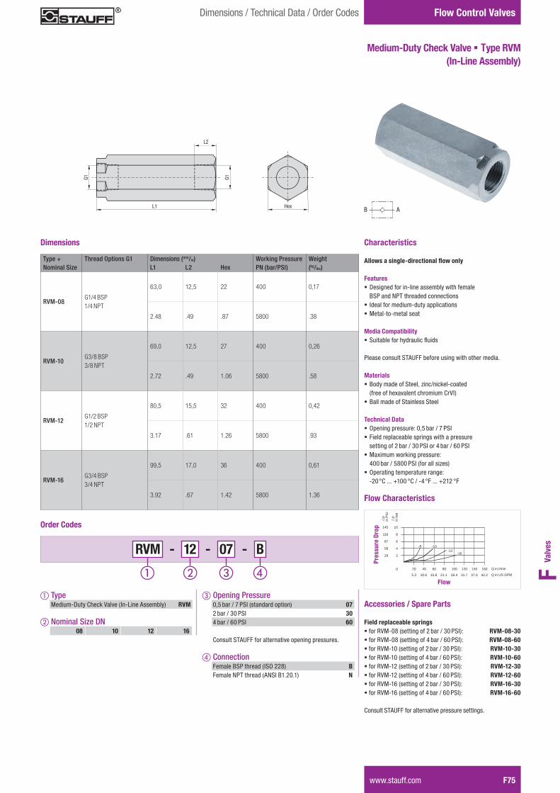
Flow Characteristics
Accessories / Spare Parts Field replaceable springs � for RVM-08 (setting of 2 bar / 30 PSI): RVM-08-30 � for RVM-08 (setting of 4 bar / 60 PSI): RVM-08-60 � for RVM-10 (setting of 2 bar / 30 PSI): RVM-10-30 � for RVM-10 (setting of 4 bar / 60 PSI): RVM-10-60 � for RVM-12 (setting of 2 bar / 30 PSI): RVM-12-30 � for RVM-12 (setting of 4 bar / 60 PSI): RVM-12-60 � for RVM-16 (setting of 2 bar / 30 PSI): RVM-16-30 � for RVM-16 (setting of 4 bar / 60 PSI): RVM-16-60 Consult STAUFF for alternative pressure settings.
B A
Symbol
Dimensions
RVM - 12 - 07 - B
Order Codes
c Opening Pressure 0,5 bar / 7 PSI (standard option) 07 2 bar / 30 PSI 30 4 bar / 60 PSI 60
Consult STAUFF for alternative opening pressures.
d Connection Female BSP thread (ISO 228) B Female NPT thread (ANSI B1.20.1) N
a Type Medium-Duty Check Valve (In-Line Assembly) RVM
b Nominal Size DN08 10 12 16
Type + Thread Options G1 Dimensions (mm/in) Working Pressure WeightNominal Size L1 L2 Hex PN (bar/PSI) (kg/lbs)
RVM-08G1/4 BSP 1/4 NPT
63,0 12,5 22 400 0,17
2.48 .49 .87 5800 .38
RVM-10G3/8 BSP 3/8 NPT
69,0 12,5 27 400 0,26
2.72 .49 1.06 5800 .58
RVM-12G1/2 BSP 1/2 NPT
80,5 15,5 32 400 0,42
3.17 .61 1.26 5800 .93
RVM-16G3/4 BSP 3/4 NPT
99,5 17,0 36 400 0,61
3.92 .67 1.42 5800 1.36
Handle Turns
20
2
0
4
6
8
10
-8 -10
-12-16
�p
in b
ar
40 60 80 100 120 140 160 Q in l/min
5.3 10.6 15.8 21.1 26.4 31.7 37.0 42.2 Q in US GPM
29
58
87
116
145
�p
in P
SI
Pres
sure
Dro
p
Flow
Ventile BM 2011-02-29.indd 75 04.03.2011 18:27:37

100
80
60
40
20
10
5
0.250.5 1 1.5 2 2.5 3 3.5 4 4.5 5 5.5 6
6.5
7
7.5
88.5
9
9.510
0 50 100 150 200 250 300 350 Q in l/min
Throttle per revolution
p in
bar
100
80
60
40
20
10
5
1 20.250.5 1.5 2.5 3 3.5 4 4.5 5 5.5 6 6.5 7 7.5 8
8.5
9
9.5
10
0 25 50 75 100 125 150 175 Q in l/min
Throttle per revolution
p in
bar
100
80
60
40
20
10
5
0.510.25 1.5 2 2.5 3 3.5 4 4.5 5 5.5 6 6.5 7 7.5 8 8.5 9
9.5
10
0 20 40 60 80 100 120 140 Q in l/min
Throttle per revolution
p in
bar
100
80
60
40
20
10
5
0.25 0.5 1 1.5 2 2.5 3 3.5 4 4.5 5 5.5 66.5
7
7.5
8
0 10 20 30 40 50 60 70 75 Q in l/min
Throttle per revolution
p in
bar
0.50.25 1 1.5 2 2.5 3 3.5 4 4.5
1005
80
60
40
20
10
5
0 10 20 30 40 50 60 Q in l/min
Throttle per revolution
p in
bar
Flow Control Valves
F76 www.stauff.com
Nominal Flow Rate vs. Pressure Drop
Flow Characteristics
p in b
ar
12
10
8
6
4
2
Q in l/min
0,5
14
100 200 300 400 500 600
-06 -08 -10 -12 -16 -20
-25
-30
-40
p Characteristic curve free flow through check valve
Flow direction: B–A
p in P
SI
174
145
116
203
Q in US GPM26 52 78 104 130 156
58
29
7
87
DRV DRVP RV DN 06-40
DV DRV DVP DRVP DVE DN 08
rp
in b
ar
rp
in P
SI
1450
1160
870
580
290
145
72.5
0 3 5.5 8 10.5 13 16 Q in US GPM
Q in l/min
Throttle per revolution0.25 1 1.5 2 2.5 3 3.5 4
0.5
100
80
60
40
20
10
5
0 2 4 6 8 10 12 14
4.5
5
Q in l/min
p in
bar
DV DRV DVP DRVP DVE DN 06
rp
in b
ar
rp
in P
SI1450
1160
870
580
290
145
72.5
0 .5 1.0 1.6 2.1 2.6 3.2 3.7 Q in US GPM
Q in l/min
DV DRV DVP DRVP DVE DN 12
rp
in b
ar
rp
in P
SI
1450
1160
870
580
290
145
72.5
0 5.5 10.5 16 21 32 37 Q in US GPM
Q in l/min
DV DRV DVP DRVP DVE DN 10
rp
in b
ar
rp
in P
SI
1450
1160
870
580
290
145
72.5
0 3 5.5 8 10.5 16 18 Q in US GPM
Q in l/min
13 19 26
DV DRV DVP DRVP DVE DN 20-40
rp
in b
ar
rp
in P
SI
1450
1160
870
580
290
145
72.5
0 13 26 39 52 78 91 Q in US GPM
Q in l/min
DV DRV DVP DRVP DVE DN 16
rp
in b
ar
rp
in P
SI
1450
1160
870
580
290
145
72.5
0 6.5 13 19.5 26 39 45.5 Q in US GPM
Q in l/min
32.5 65
Please note: The flow characteristics mentioned on this page are valid for mineral oils with a density of 0,86 kg/dm³ and the kinematic viscosity of 35 mm²/s (35 cSt). The characteristics have been determined in accordance to ISO 3968.
Ventile BM 2011-02-29.indd 76 04.03.2011 18:27:39
Recommended