Agenda• AMS-IX
• 100Gbit/s technology
• Problem statement
• Optical Amplifier development
• Metro DWDM equipment
• Production results
Sunday, October 21, 12()
Agenda• AMS-IX
• 100Gbit/s technology
• Problem statement
• Optical Amplification
• Metro DWDM equipment
• Production results
Sunday, October 21, 12()

AMS-IX• Amsterdam Internet Exchange
• Not for profit organization.
• 516 Networks (ASes).
• 1857Gbit/s peak
• 911Gbit/s average over the last 16 months
• 11 Operational sites.
• Equinix AM3 almost ready.
• 24 x 100Gbit/s backbone links.
Sunday, October 21, 12()

Agenda• AMS-IX
• 100Gbit/s technology
• Problem statement
• Optical Amplifier development
• Metro DWDM equipment
• Production results
Sunday, October 21, 12()
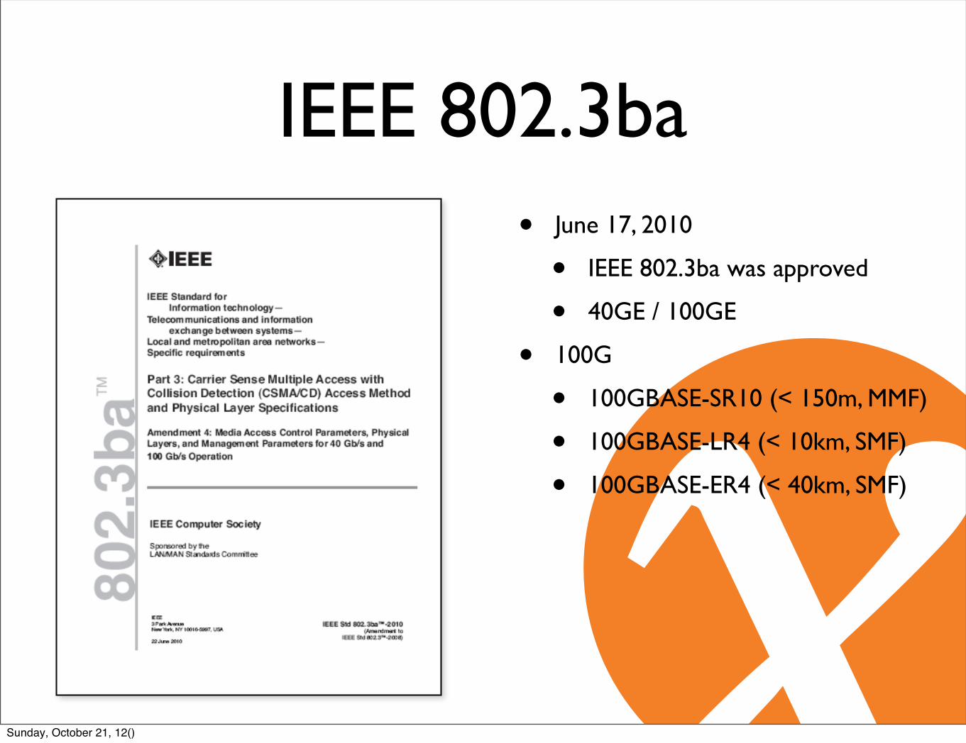
IEEE 802.3ba• June 17, 2010
• IEEE 802.3ba was approved
• 40GE / 100GE
• 100G
• 100GBASE-SR10 (< 150m, MMF)
• 100GBASE-LR4 (< 10km, SMF)
• 100GBASE-ER4 (< 40km, SMF)
Sunday, October 21, 12()
IEEE 802.3baIEEE Std 802.3ba-2010 AMENDMENT TO IEEE Std 802.3-2008: CSMA/CD
108 Copyright © 2010 IEEE. All rights reserved.
d) The PMA service interface, which, when physically implemented as CAUI (100 Gigabit AttachmentUnit Interface) at an observable interconnection port, uses a 10 lane data path as specified inAnnex 83A or Annex 83B.
e) The PMD service interface, which, when physically implemented as XLPPI (40 Gigabit ParallelPhysical Interface) at an observable interconnection port, uses a 4 lane data path as specified inAnnex 86A.
f) The PMD service interface, which, when physically implemented as CPPI (100 Gigabit ParallelPhysical Interface) at an observable interconnection port, uses a 10 lane data path as specified inAnnex 86A.
g) The MDIs as specified in Clause 84 for 40GBASE-KR4, in Clause 85 for 40GBASE-CR4, inClause 86 for 40GBASE-SR4, Clause 87 for 40GBASE-LR4 and in Clause 88 for 100GBASE-LR4and 100GBASE-ER4 all use a 4 lane data path.
h) The MDIs as specified in Clause 85 for 100GBASE-CR10, and in Clause 86 for 100GBASE-SR10use a 10 lane data path.
AN 2
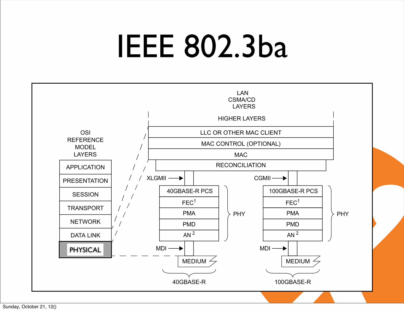
Figure 80–1—Architectural positioning of 40 Gigabit and 100 Gigabit Ethernet
LANCSMA/CD
LAYERS
LLC OR OTHER MAC CLIENT
MAC
HIGHER LAYERS
MAC CONTROL (OPTIONAL)
PRESENTATION
APPLICATION
SESSION
TRANSPORT
NETWORK
DATA LINK
PHYSICAL
OSIREFERENCE
MODELLAYERS
MDI
PMD
PMA
CGMII
FEC1
100GBASE-R PCS
100GBASE-R
PHY
PHY = PHYSICAL LAYER DEVICEPMA = PHYSICAL MEDIUM ATTACHMENTPMD = PHYSICAL MEDIUM DEPENDENTXLGMII = 40 Gb/s MEDIA INDEPENDENT INTERFACE
NOTE 1—OPTIONAL OR OMITTED DEPENDING ON PHY TYPENOTE 2—CONDITIONAL BASED ON PHY TYPE
AN = AUTO-NEGOTIATIONCGMII = 100 Gb/s MEDIA INDEPENDENT INTERFACEFEC = FORWARD ERROR CORRECTIONLLC = LOGICAL LINK CONTROLMAC = MEDIA ACCESS CONTROLMDI = MEDIUM DEPENDENT INTERFACEPCS = PHYSICAL CODING SUBLAYER
RECONCILIATION
MEDIUM
AN 2PMD
PMA
FEC1
40GBASE-R PCS
40GBASE-R
PHY
MEDIUM
MDI
XLGMII
PHYSICAL
Sunday, October 21, 12()

IEEE 802.3ba
AMENDMENT TO IEEE Std 802.3-2008: CSMA/CD IEEE Std 802.3ba-2010
Copyright © 2010 IEEE. All rights reserved. 123
81. Reconciliation Sublayer (RS) and Media Independent Interface for 40 Gb/s and 100 Gb/s operation (XLGMII and CGMII)
81.1 Overview
This clause defines the characteristics of the Reconciliation Sublayer (RS) and the Media IndependentInterface between CSMA/CD media access controllers and various PHYs. Figure 81–1 shows therelationship of the RS and Media Independent Interface to the ISO/IEC OSI reference model. Note that thereare two variants of the Media Independent Interface in this clause, the 40 Gb/s Media Independent Interface(XLGMII) and the 100 Gb/s Media Independent Interface (CGMII).
The XLGMII and the CGMII are optional logical interfaces between the MAC sublayer and the PhysicalLayer (PHY).
The RS adapts the bit serial protocols of the MAC to the parallel format of the PCS service interface.Though the XLGMII/CGMII is an optional interface, it is used in this standard as a basis for specification.The Physical Coding Sublayer (PCS) is specified to the XLGMII/CGMII, so if not implemented, aconforming implementation shall behave functionally as if the RS and XLGMII/CGMII were implemented.
AN 2
LANCSMA/CD
LAYERS
LLC OR OTHER MAC CLIENT
MAC
HIGHER LAYERS
MAC CONTROL (OPTIONAL)
PRESENTATION
APPLICATION
SESSION
TRANSPORT
NETWORK
DATA LINK
PHYSICAL
OSIREFERENCE
MODELLAYERS
MDI
PMD
PMA
CGMII
FEC1
100GBASE-R PCS
100GBASE-R
PHY
PHY = PHYSICAL LAYER DEVICEPMA = PHYSICAL MEDIUM ATTACHMENTPMD = PHYSICAL MEDIUM DEPENDENTXLGMII = 40 Gb/s MEDIA INDEPENDENT INTERFACE
NOTE 1—OPTIONAL OR OMITTED DEPENDING ON PHY TYPENOTE 2—CONDITIONAL BASED ON PHY TYPE
AN = AUTO-NEGOTIATIONCGMII = 100 Gb/s MEDIA INDEPENDENT INTERFACEFEC = FORWARD ERROR CORRECTIONLLC = LOGICAL LINK CONTROLMAC = MEDIA ACCESS CONTROLMDI = MEDIUM DEPENDENT INTERFACEPCS = PHYSICAL CODING SUBLAYER
RECONCILIATION
MEDIUM
AN 2
PMD
PMA
FEC1
40GBASE-R PCS
40GBASE-R
PHY
MEDIUM
MDI
XLGMII
Figure 81–1—RS and MII relationship to the ISO/IEC Open Systems Interconnection (OSI) reference model and the IEEE 802.3 CSMA/CD LAN model
Sunday, October 21, 12()

IEEE 802.3baAMENDMENT TO IEEE Std 802.3-2008: CSMA/CD IEEE Std 802.3ba-2010
Copyright © 2010 IEEE. All rights reserved. 187
The following guidelines apply to the partitioning of PMAs:
a) The inter-sublayer service interface, defined in 80.3, is used for the PMA, FEC, and PMD serviceinterfaces supporting a flexible architecture with optional FEC and multiple PMA sublayers.1) An instance of this interface can only connect service interfaces with the same number of lanes,
where the lanes operate at the same rate.b) XLAUI and CAUI are physical instantiations of the connection between two adjacent PMA
sublayers.1) As a physical instantiation, it defines electrical and timing specification as well as requiring a
receive re-timing function2) XLAUI is a 10.3125 GBd by 4 lane physical instantiation of the respective 40 Gb/s connection3) CAUI is a 10.3125 GBd by 10 lane physical instantiation of the respective 100 Gb/s connection
c) The abstract inter-sublayer service interface can be physically instantiated as a XLAUI or CAUI,using associated PMAs to map to the appropriate number of lanes.
d) Opportunities for optional test-pattern generation, optional test-pattern detection, optional localloopback and optional remote loopback are dependent upon the location of the PMA sublayer in theimplementation. See Figure 83–5.
e) A minimum of one PMA sublayer is required in a PHY.f) A maximum of four PMA sublayers are addressable as MDIO MMDs.
Figure 83–2—Example 40GBASE-R and 100GBASE-R PMA layering
PCS = PHYSICAL CODING SUBLAYERPMA = PHYSICAL MEDIUM ATTACHMENTPMD = PHYSICAL MEDIUM DEPENDENTXLAUI = 40 Gb/s ATTACHMENT UNIT INTERFACEXLGMII = 40 Gb/s MEDIA INDEPENDENT INTERFACE
CAUI = 100 Gb/s ATTACHMENT UNIT INTERFACECGMII = 100 Gb/s MEDIA INDEPENDENT INTERFACEFEC = FORWARD ERROR CORRECTIONMAC = MEDIA ACCESS CONTROLMDI = MEDIUM DEPENDENT INTERFACEMMD = MDIO MANAGEABLE DEVICE
FEC
MAC AND HIGHER LAYERS
RECONCILIATION
XLGMII
PMA (4:4)
XLAUI
PMD
40GBASE-R PCS
PMA (4:4)
FEC
PMA (20:10)
100GBASE-R PCS
PMA (10:20)
CGMII
CAUI
MDI
100GBASE-R
MEDIUM
PMD
40GBASE-R
MEDIUM
MDI
PMD SERVICEINTERFACE
PMD SERVICEINTERFACE
PMA (4:4) PMA (20:10)
XLAUI CAUI
PMA (4:4) PMA (10:4) MMD 8
MMD 9
MMD 10
MMD 11
MMD 8
MMD 9
MMD 10
MMD 11
MMD 1MMD 1
Sunday, October 21, 12()
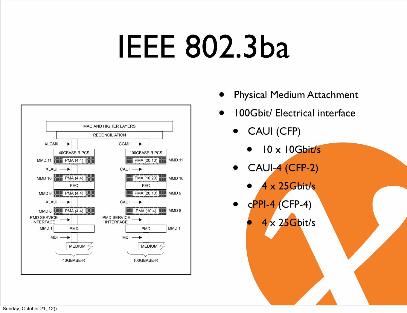
IEEE 802.3ba• Physical Medium Attachment
• 100Gbit/ Electrical interface
• CAUI (CFP)
• 10 x 10Gbit/s
• CAUI-4 (CFP-2)
• 4 x 25Gbit/s
• cPPI-4 (CFP-4)
• 4 x 25Gbit/s
AMENDMENT TO IEEE Std 802.3-2008: CSMA/CD IEEE Std 802.3ba-2010
Copyright © 2010 IEEE. All rights reserved. 187
The following guidelines apply to the partitioning of PMAs:
a) The inter-sublayer service interface, defined in 80.3, is used for the PMA, FEC, and PMD serviceinterfaces supporting a flexible architecture with optional FEC and multiple PMA sublayers.1) An instance of this interface can only connect service interfaces with the same number of lanes,
where the lanes operate at the same rate.b) XLAUI and CAUI are physical instantiations of the connection between two adjacent PMA
sublayers.1) As a physical instantiation, it defines electrical and timing specification as well as requiring a
receive re-timing function2) XLAUI is a 10.3125 GBd by 4 lane physical instantiation of the respective 40 Gb/s connection3) CAUI is a 10.3125 GBd by 10 lane physical instantiation of the respective 100 Gb/s connection
c) The abstract inter-sublayer service interface can be physically instantiated as a XLAUI or CAUI,using associated PMAs to map to the appropriate number of lanes.
d) Opportunities for optional test-pattern generation, optional test-pattern detection, optional localloopback and optional remote loopback are dependent upon the location of the PMA sublayer in theimplementation. See Figure 83–5.
e) A minimum of one PMA sublayer is required in a PHY.f) A maximum of four PMA sublayers are addressable as MDIO MMDs.
Figure 83–2—Example 40GBASE-R and 100GBASE-R PMA layering
PCS = PHYSICAL CODING SUBLAYERPMA = PHYSICAL MEDIUM ATTACHMENTPMD = PHYSICAL MEDIUM DEPENDENTXLAUI = 40 Gb/s ATTACHMENT UNIT INTERFACEXLGMII = 40 Gb/s MEDIA INDEPENDENT INTERFACE
CAUI = 100 Gb/s ATTACHMENT UNIT INTERFACECGMII = 100 Gb/s MEDIA INDEPENDENT INTERFACEFEC = FORWARD ERROR CORRECTIONMAC = MEDIA ACCESS CONTROLMDI = MEDIUM DEPENDENT INTERFACEMMD = MDIO MANAGEABLE DEVICE
FEC
MAC AND HIGHER LAYERS
RECONCILIATION
XLGMII
PMA (4:4)
XLAUI
PMD
40GBASE-R PCS
PMA (4:4)
FEC
PMA (20:10)
100GBASE-R PCS
PMA (10:20)
CGMII
CAUI
MDI
100GBASE-R
MEDIUM
PMD
40GBASE-R
MEDIUM
MDI
PMD SERVICEINTERFACE
PMD SERVICEINTERFACE
PMA (4:4) PMA (20:10)
XLAUI CAUI
PMA (4:4) PMA (10:4) MMD 8
MMD 9
MMD 10
MMD 11
MMD 8
MMD 9
MMD 10
MMD 11
MMD 1MMD 1
Sunday, October 21, 12()

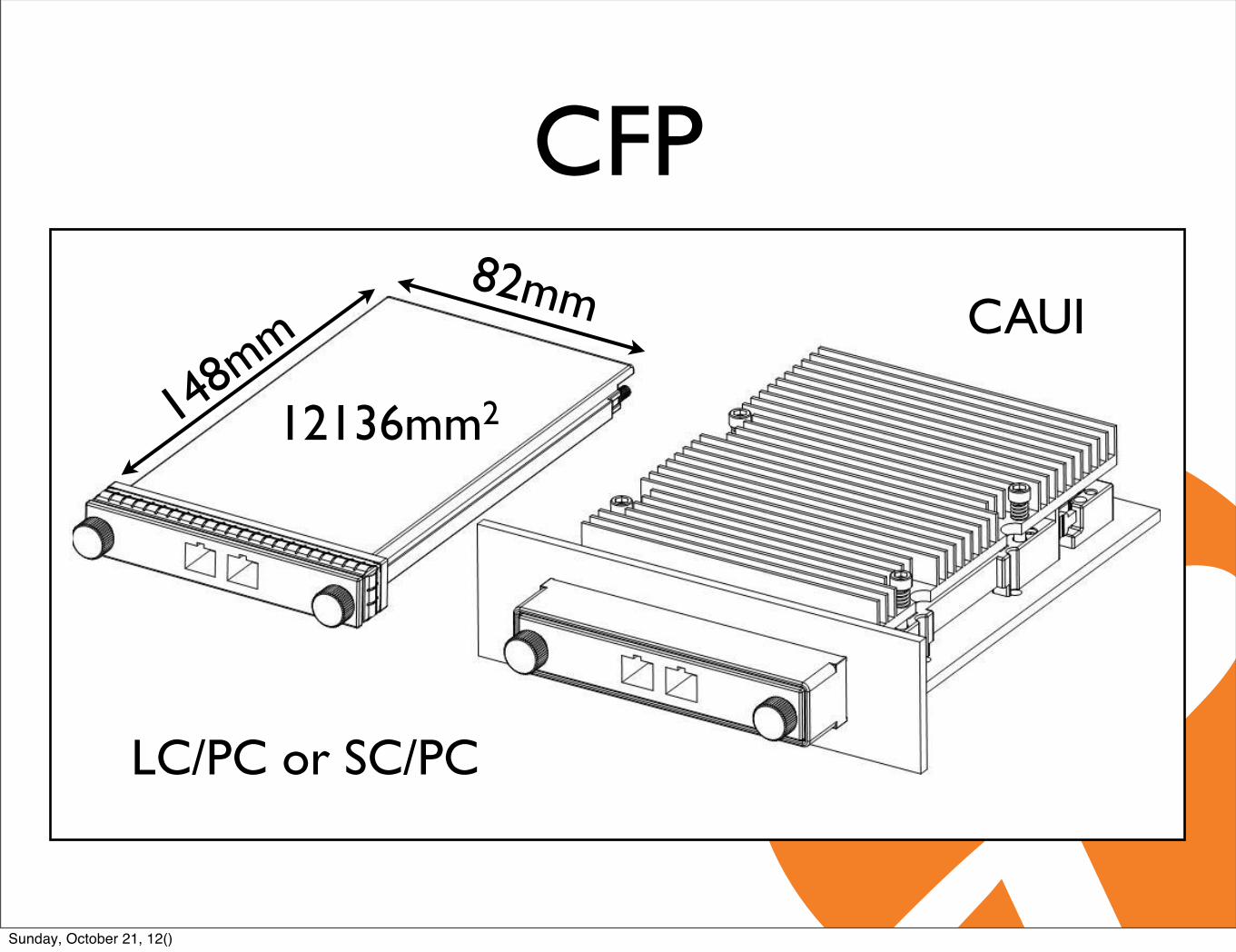
CFP• C Form-factor Pluggable (CFP)
• 100Gbit/ Electrical interface
• CAUI
• CFP
• 10 x 10Gbit/s
• Optical Interface
• Multi mode 10x10Gbit/s
• Single mode 4x25Gbit/s
CAUI CFP
10x10Gbit/s 4x25Gbit/s
electrical optical
Sunday, October 21, 12()
CFP
Page 31 CFP MSA, Revision 1.4
5 MECHANICAL SPECIFICATIONS
5.1 Mechanical Overview The CFP MSA module is designed to be assembled into a host system with a railing system. The railing system assembly is fabricated within the host system, and the CFP MSA module may be inserted at a later time. Shown in Figure 5-1 is a drawing of the CFP module and a CFP module inserted into a host system with a riding heat sink.
Figure 5-1: CFP Module & CFP Module Mated in Host System
Starting in Figure 5-2, is an overview of the mechanical assembly with the subsequent figures show the constituent elements in greater detail. The final dimensions are located in a separate document hosted on the CFP MSA Website (www.cfp-msa.org).
LC/PC or SC/PC
148m
m82mm
12136mm2
CAUI
Sunday, October 21, 12()
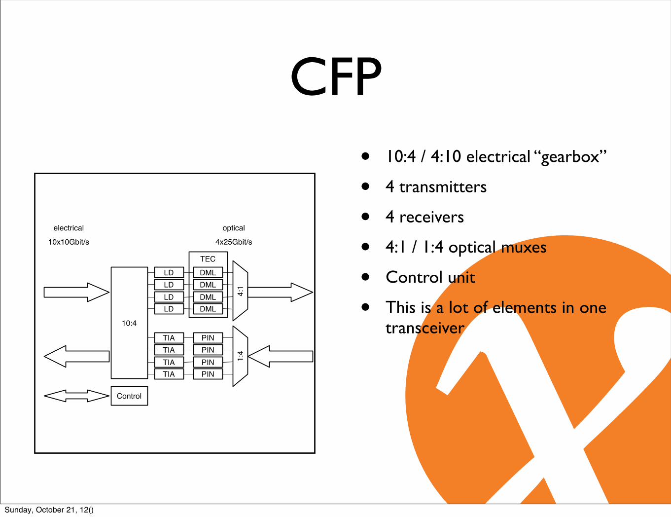
CFP• 10:4 / 4:10 electrical “gearbox”
• 4 transmitters
• 4 receivers
• 4:1 / 1:4 optical muxes
• Control unit
• This is a lot of elements in one transceiver
10x10Gbit/s 4x25Gbit/s
electrical optical
TEC
PINPINPINPIN
1:4
TIATIATIATIA
DMLDMLDMLDML
4:1
LDLDLDLD
Control
10:4
Sunday, October 21, 12()

10x10 MSA• Outside IEEE initiative
• 26 participants
• Network operators
• AMS-IX among others
• No Cisco, Juniper, Alcatel
• Works in Juniper though
• Less expensive 100GBASE-LR4 between:
• 100GBASE-SR10 supports up to 150m (OM4 MMF)
• 100GBASE-LR4 supports up to 10km (SMF)
Sunday, October 21, 12()

10x10 MSA• 10x10Gbit/s electrical and optical
• 10 Lasers
• 10 Transceivers
• 10:1 / 1:10 optical muxes
• No “gearbox”
• Retiming circuits instead
• Considerably cheaper LR-4
• Less power hungry than LR-4
10x10Gbit/s 4x25Gbit/s
electrical optical
TEC
PIN
PINPIN
1:10
TIA
TIATIA
DML
DMLDML
10:1
LD
LDLD
Control
retimer
retimerretimer
retimer
retimerretimer
Sunday, October 21, 12()

CFP-2 (future)• Smaller modules than CFPs
• 4x25Gbit/s electrical and optical
• 4 Lasers
• 4 Transceivers
• 4:1 / 4:1 optical muxes
• No “gearbox”
• Still Retiming circuits
• Cheaper than CFPs
• Less power hungry than CFPs
• 10x10 MSA would require a gearbox
4x25Gbit/s 4x25Gbit/s
electrical optical
TEC
PIN
PINPIN
1:4
TIA
TIATIA
DML
DMLDML
4:1
LD
LDLD
Control
retimer
retimerretimer
retimer
retimerretimer
DMLLDretimer
DMLTIAretimer
Sunday, October 21, 12()

CFP-4 (future)• Smaller modules than CFP-2
• 4x25Gbit/s electrical and optical
• 4 Lasers
• 4 Transceivers
• 4:1 / 4:1 optical muxes
• No retiming units
• Require external retiming units.
4x25Gbit/s 4x25Gbit/s
electrical optical
TEC
PIN
PINPIN
1:4
TIA
TIATIA
DML
DMLDML
4:1
LD
LDLD
Control
DMLLD
DMLTIA
Sunday, October 21, 12()
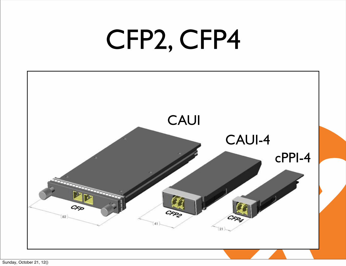
CAUI
cPPI-4
CFP2, CFP4
CAUI-4
Sunday, October 21, 12()

Summary• Transceiver type: CFP
• Electrical Interface
• 10x10G bit/s
• Optical Interfaces
• 100GBASE-SR10 (< 150m, MMF)
• 10x10MSA (<2km, SMF).
• 100GBASE-LR4 (< 10km, SMF)
• 100GBASE-ER4 (< 40km, SMF)
Sunday, October 21, 12()

Agenda• AMS-IX
• 100Gbit/s technology
• Problem statement
• Optical Amplifier development
• Metro DWDM equipment
• Production results
Sunday, October 21, 12()
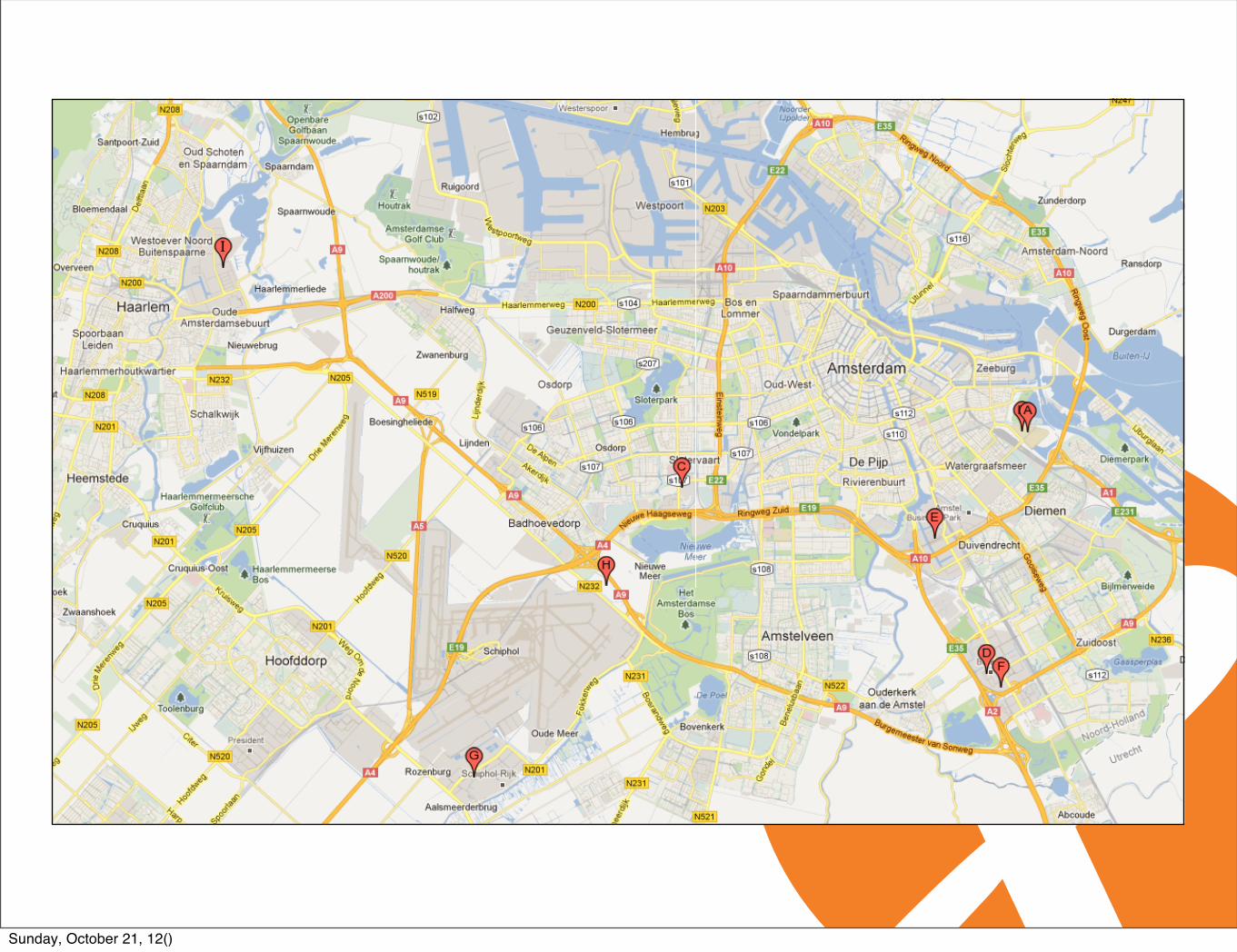
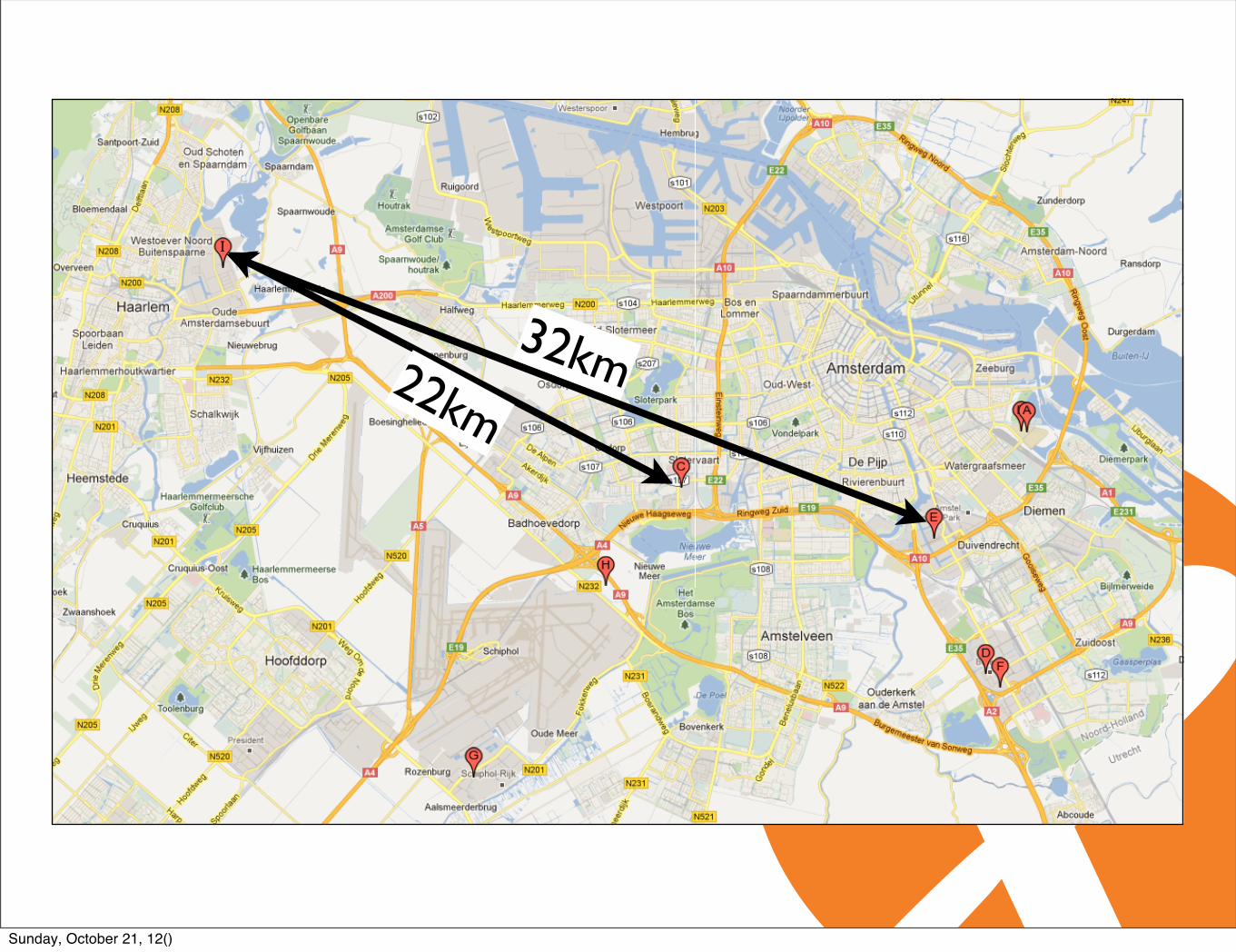
Map data ©2012 Google -
To see all the details that are visible on thescreen, use the "Print" link next to the map.
AMS-IX locations - Google Maps https://maps.google.com/
1 of 2 7/4/12(27) 5:12 PMSunday, October 21, 12()

Map data ©2012 Google -
To see all the details that are visible on thescreen, use the "Print" link next to the map.
AMS-IX locations - Google Maps https://maps.google.com/
1 of 2 7/4/12(27) 5:12 PM
32km22km
Sunday, October 21, 12()

Problem Statement• Currently available 100Gb/s CFPs:
• 10x10 for 2km.
• 100G-LR4 for 10km.
• Many of our links are too long for the available 100Gbit/s optics.
• 100G-ER4 for 40km was (and is) not available to us.
Sunday, October 21, 12()
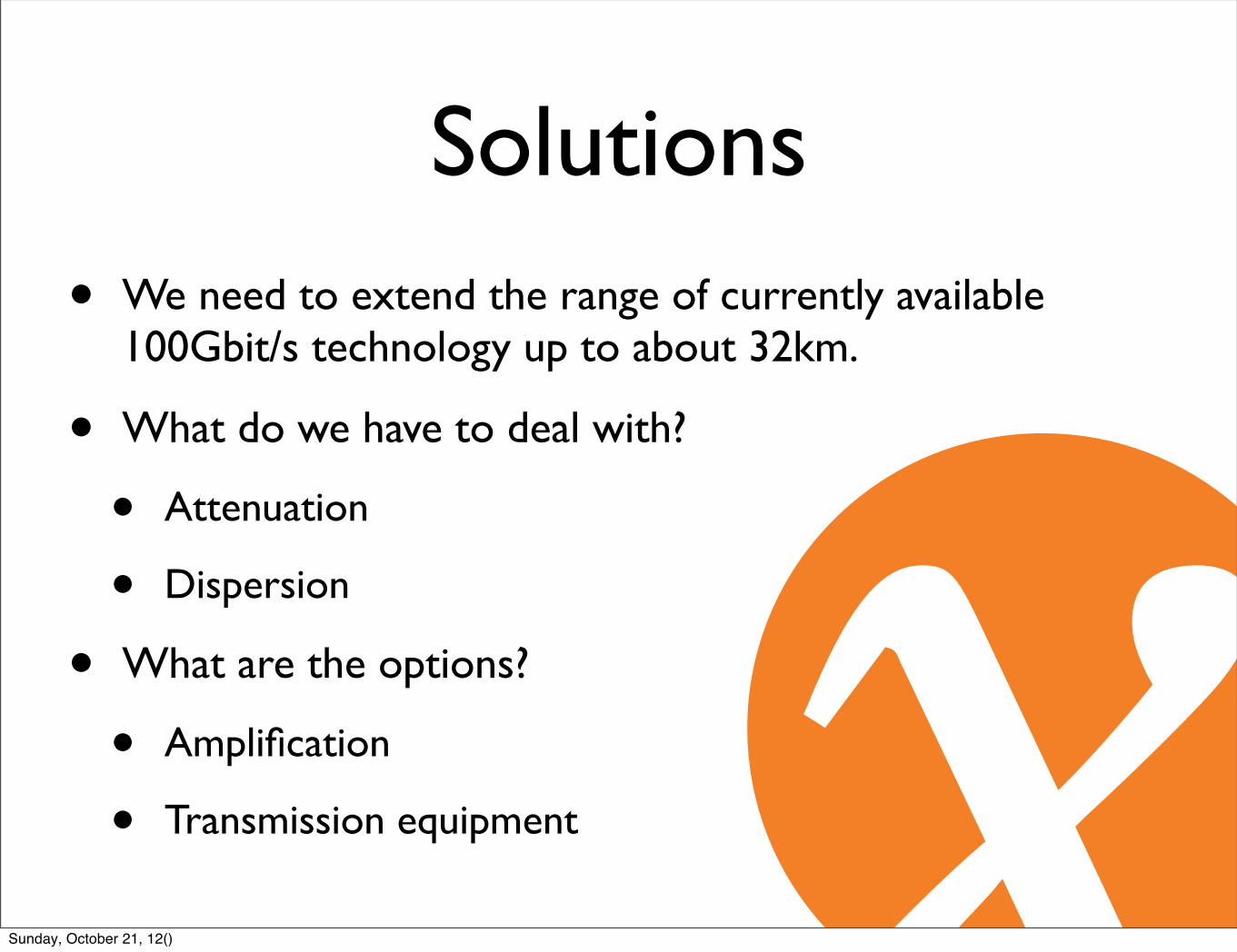
Solutions• We need to extend the range of currently available
100Gbit/s technology up to about 32km.
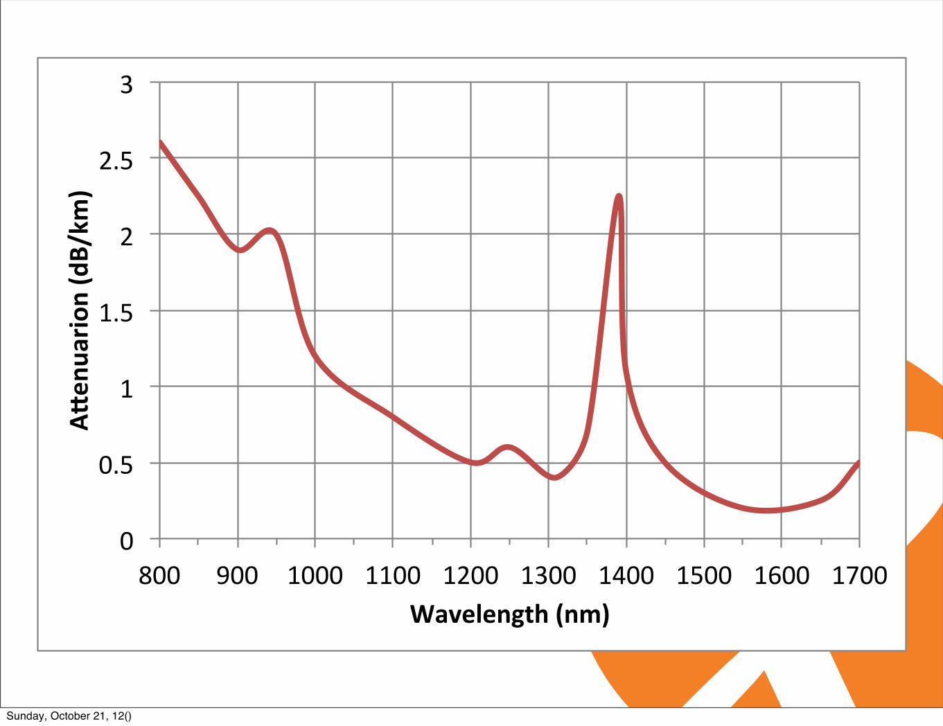
• What do we have to deal with?
• Attenuation
• Dispersion
• What are the options?
• Amplification
• Transmission equipment
Sunday, October 21, 12()
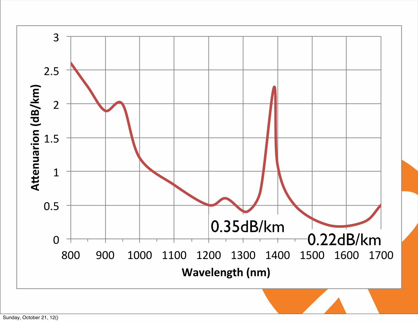
0"
0.5"
1"
1.5"
2"
2.5"
3"
800" 900" 1000" 1100" 1200" 1300" 1400" 1500" 1600" 1700"
A"en
uario
n*(dB/km
)*
Wavelength*(nm)*
0.35dB/km0.22dB/km
Sunday, October 21, 12()

Doped Fibre Amplifier
pump laser(s)
Doped fibre
Pulse
Pulse
Sunday, October 21, 12()

Semiconductor
electrical current
Pulse
Pulse
Sunday, October 21, 12()
Optical Amplifier
Sunday, October 21, 12()

Optical Amplifier
Sunday, October 21, 12()

Optical Amplifier
Sunday, October 21, 12()

Optical Amplifier
Sunday, October 21, 12()

Optical Amplifier
Sunday, October 21, 12()

Optical Amplifier
Sunday, October 21, 12()

Optical Amplifier
Sunday, October 21, 12()

Optical Amplifier
Sunday, October 21, 12()

Optical Amplifier
Sunday, October 21, 12()

Optical Amplifier
Sunday, October 21, 12()

Optical Amplifier
Sunday, October 21, 12()

Optical Amplifier
Sunday, October 21, 12()
0"
0.5"
1"
1.5"
2"
2.5"
3"
800" 900" 1000" 1100" 1200" 1300" 1400" 1500" 1600" 1700"
A"en
uario
n*(dB/km
)*
Wavelength*(nm)*
Sunday, October 21, 12()

0"
0.5"
1"
1.5"
2"
2.5"
3"
800" 900" 1000" 1100" 1200" 1300" 1400" 1500" 1600" 1700"
A"en
uario
n*(dB/km
)*
Wavelength*(nm)*
O-band
C-b
and
L-ba
nd
S-ba
ndSunday, October 21, 12()

Band Doped Fibre Amplifier
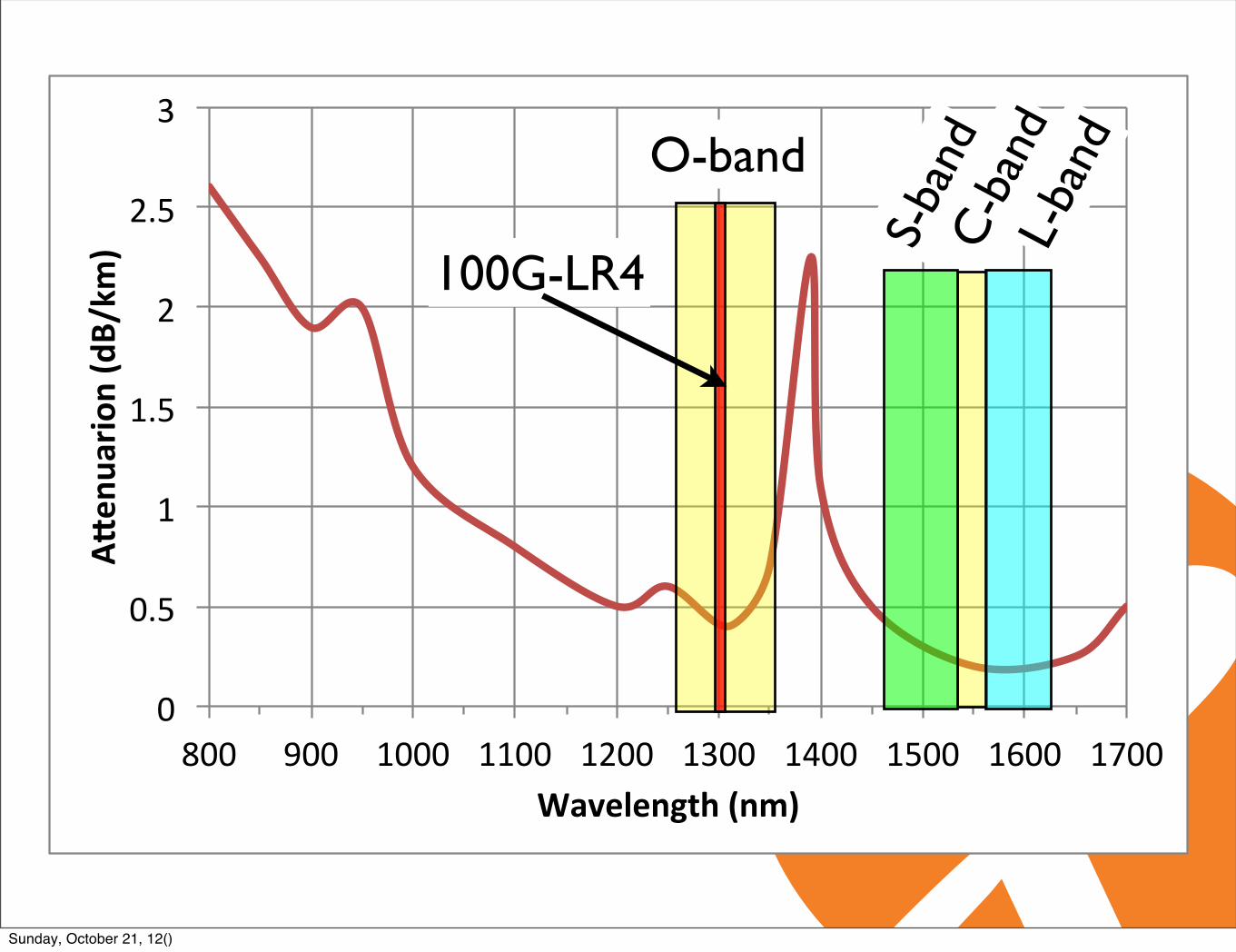
Original (O)1260 to 1360 nm
PDFA(Praseodymium doped fibre amplifier)
Short wavelengths (S)1460 to 1530 nm
TDFA(Thulium doped fibre amplifier)
Conventional (C)1530 to 1565 nm
EDFA (C-band)(Erbium doped fibre amplifier)
Long wavelengths (L)1565 to 1625 nm
EDFA (L-band)(Erbium doped fibre amplifier)
Sunday, October 21, 12()

Lane Center λ(nm)
λ Range(nm)
L0 1523 1521 to 1525L1 1531 1529 to 1533L2 1539 1537 to 1541L3 1547 1545 to 1549L4 1555 1553 to 1557L5 1563 1561 to 1565L6 1571 1569 to 1573L7 1579 1577 to 1581L8 1587 1585 to 1589L9 1595 1593 to 1597
Sunday, October 21, 12()

0"
0.5"
1"
1.5"
2"
2.5"
3"
800" 900" 1000" 1100" 1200" 1300" 1400" 1500" 1600" 1700"
A"en
uario
n*(dB/km
)*
Wavelength*(nm)*
O-band
C-b
and
L-ba
nd
S-ba
ndSunday, October 21, 12()

0"
0.5"
1"
1.5"
2"
2.5"
3"
800" 900" 1000" 1100" 1200" 1300" 1400" 1500" 1600" 1700"
A"en
uario
n*(dB/km
)*
Wavelength*(nm)*
O-band
C-b
and
L-ba
nd
S-ba
nd1
0x
10
(<
40
km
)Sunday, October 21, 12()
Lane Center λ(nm)
λ Range(nm)
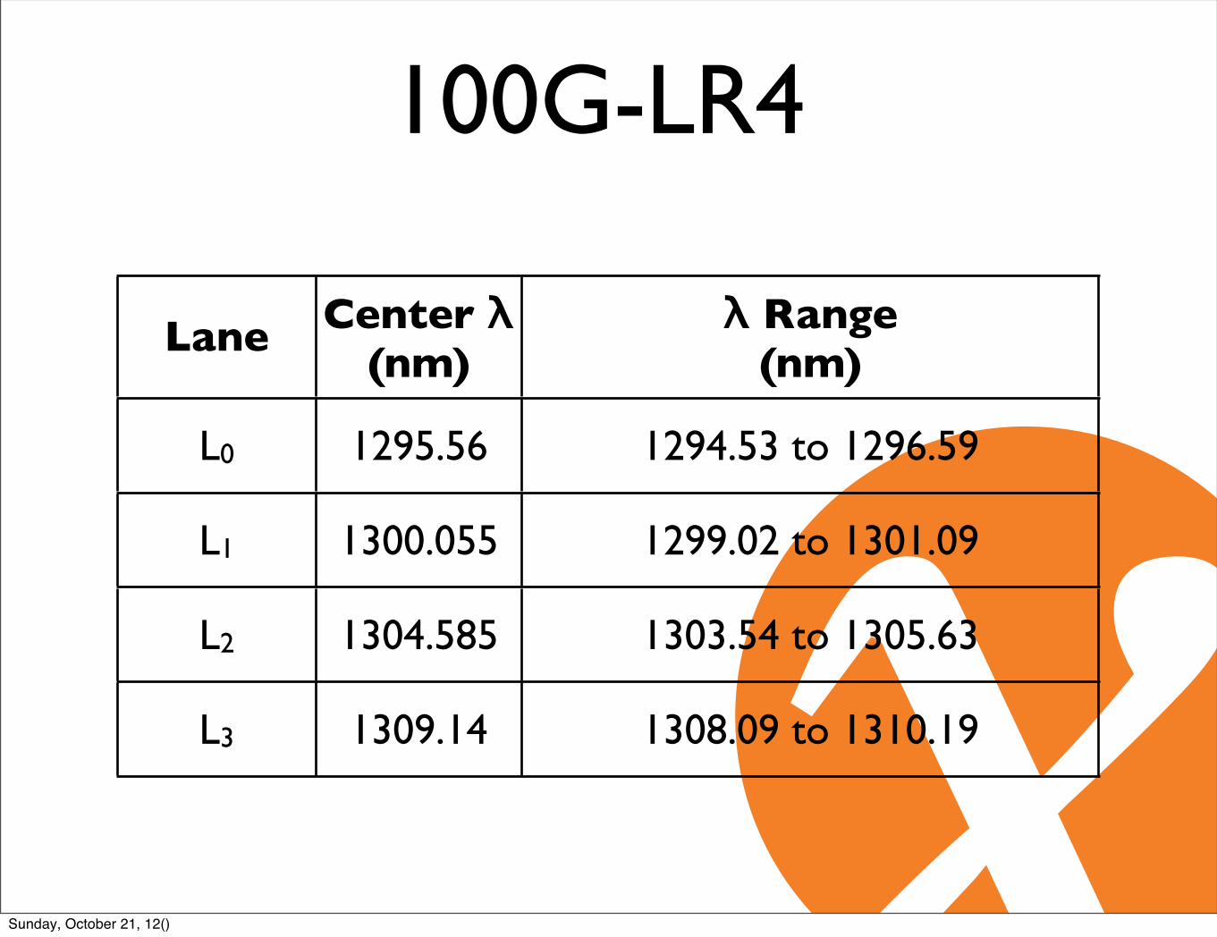
L0 1295.56 1294.53 to 1296.59
L1 1300.055 1299.02 to 1301.09
L2 1304.585 1303.54 to 1305.63
L3 1309.14 1308.09 to 1310.19
100G-LR4
Sunday, October 21, 12()

0"
0.5"
1"
1.5"
2"
2.5"
3"
800" 900" 1000" 1100" 1200" 1300" 1400" 1500" 1600" 1700"
A"en
uario
n*(dB/km
)*
Wavelength*(nm)*
O-band
C-b
and
L-ba
nd
S-ba
ndSunday, October 21, 12()
0"
0.5"
1"
1.5"
2"
2.5"
3"
800" 900" 1000" 1100" 1200" 1300" 1400" 1500" 1600" 1700"
A"en
uario
n*(dB/km
)*
Wavelength*(nm)*
O-band
C-b
and
L-ba
nd
S-ba
nd
100G-LR4
Sunday, October 21, 12()
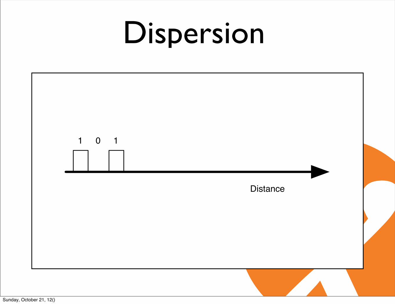
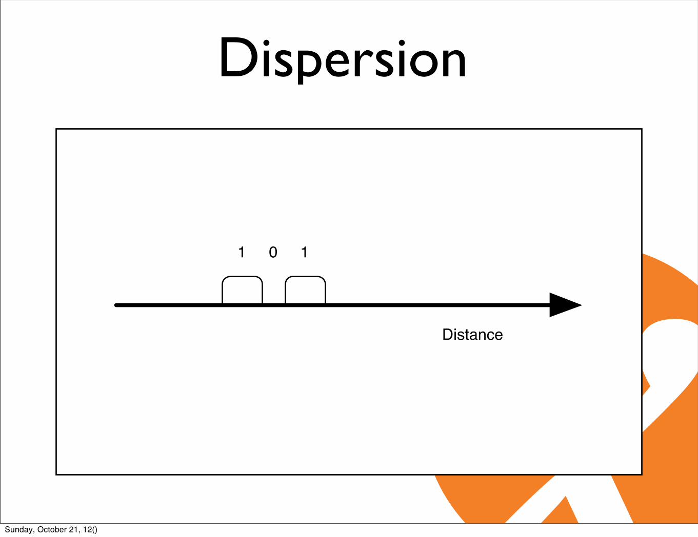
Dispersion
Distance
1 10
Sunday, October 21, 12()
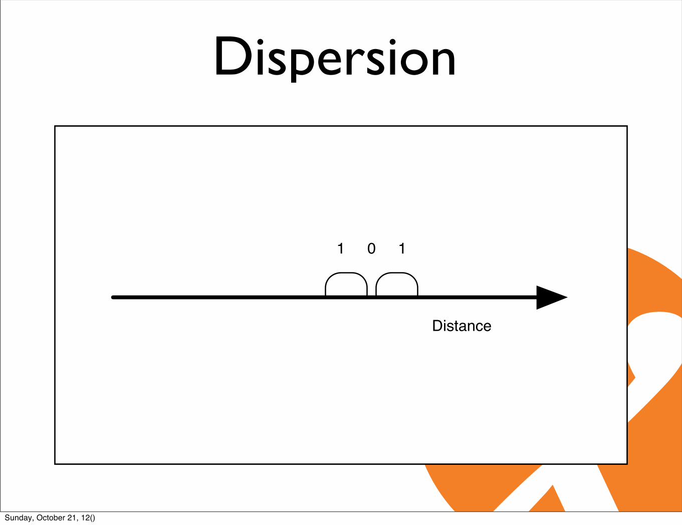
Dispersion
Distance
1 10
Sunday, October 21, 12()
Dispersion
Distance
1 10
Sunday, October 21, 12()

Dispersion
1 10
Distance
Sunday, October 21, 12()

!50$
0$
50$
100$
150$
200$
250$
300$
350$
600$ 700$ 800$ 900$ 1000$ 1100$ 1200$ 1300$ 1400$ 1500$ 1600$
M(ps/(nm*km)],
Wavelength,(nm),
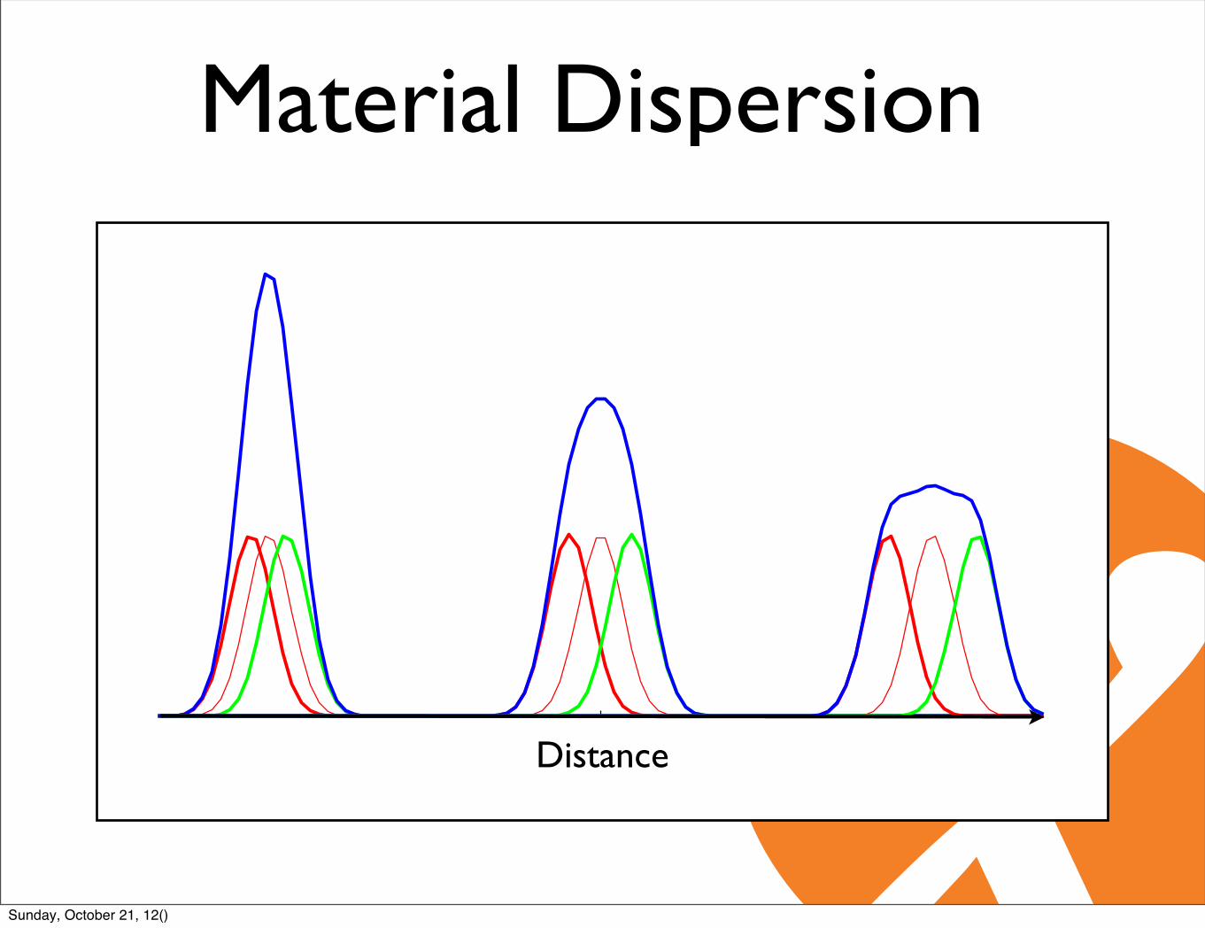
Material Dispersion
Sunday, October 21, 12()

Material Dispersion
Distance
Sunday, October 21, 12()

Material Dispersion
Distance
Sunday, October 21, 12()

Material Dispersion
Distance
Sunday, October 21, 12()
Material Dispersion
Distance
Sunday, October 21, 12()

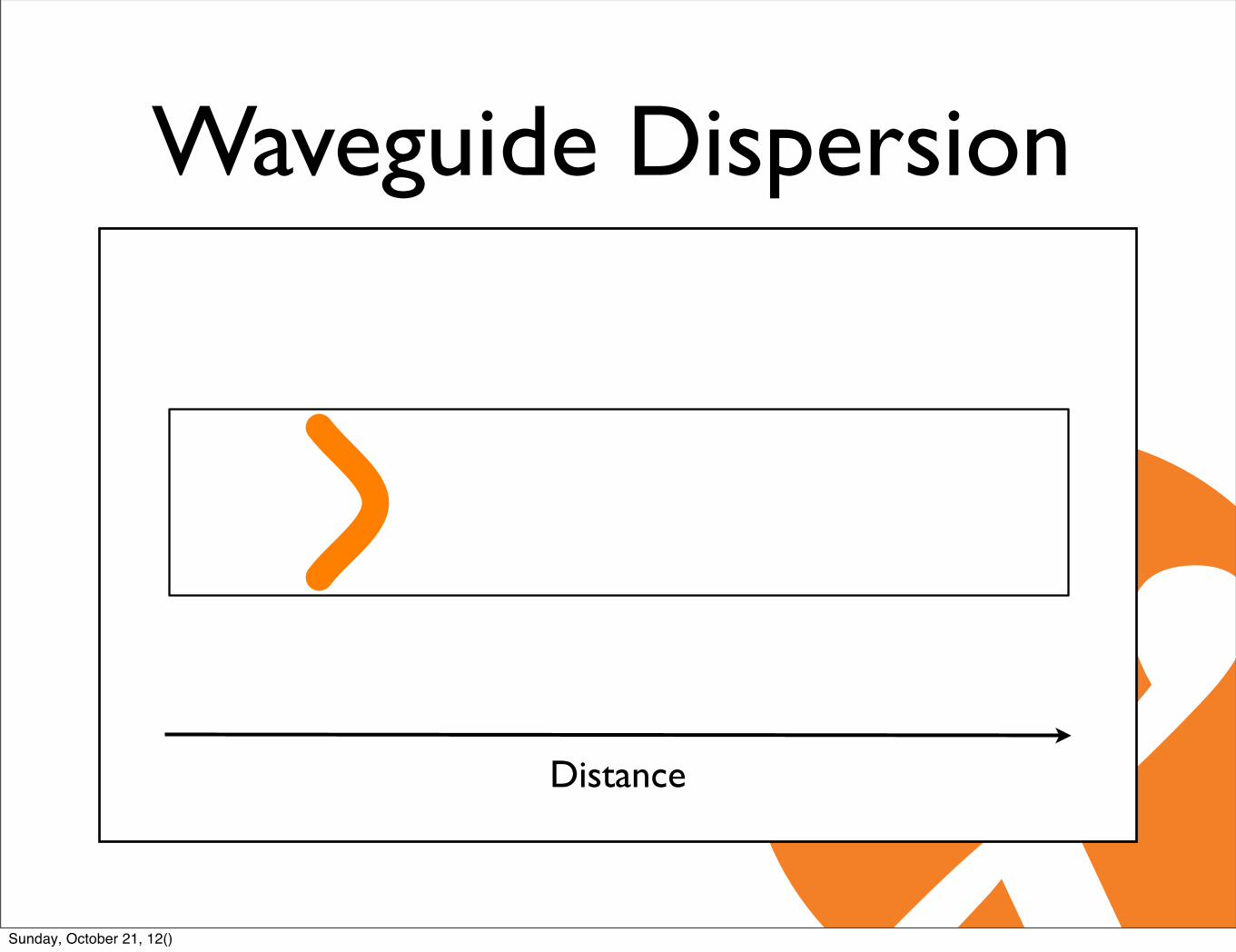
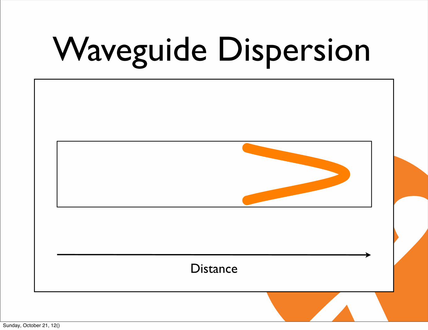
Waveguide Dispersion
Distance
Sunday, October 21, 12()
Waveguide Dispersion
Distance
Sunday, October 21, 12()

Waveguide Dispersion
Distance
Sunday, October 21, 12()
Waveguide Dispersion
Distance
Sunday, October 21, 12()
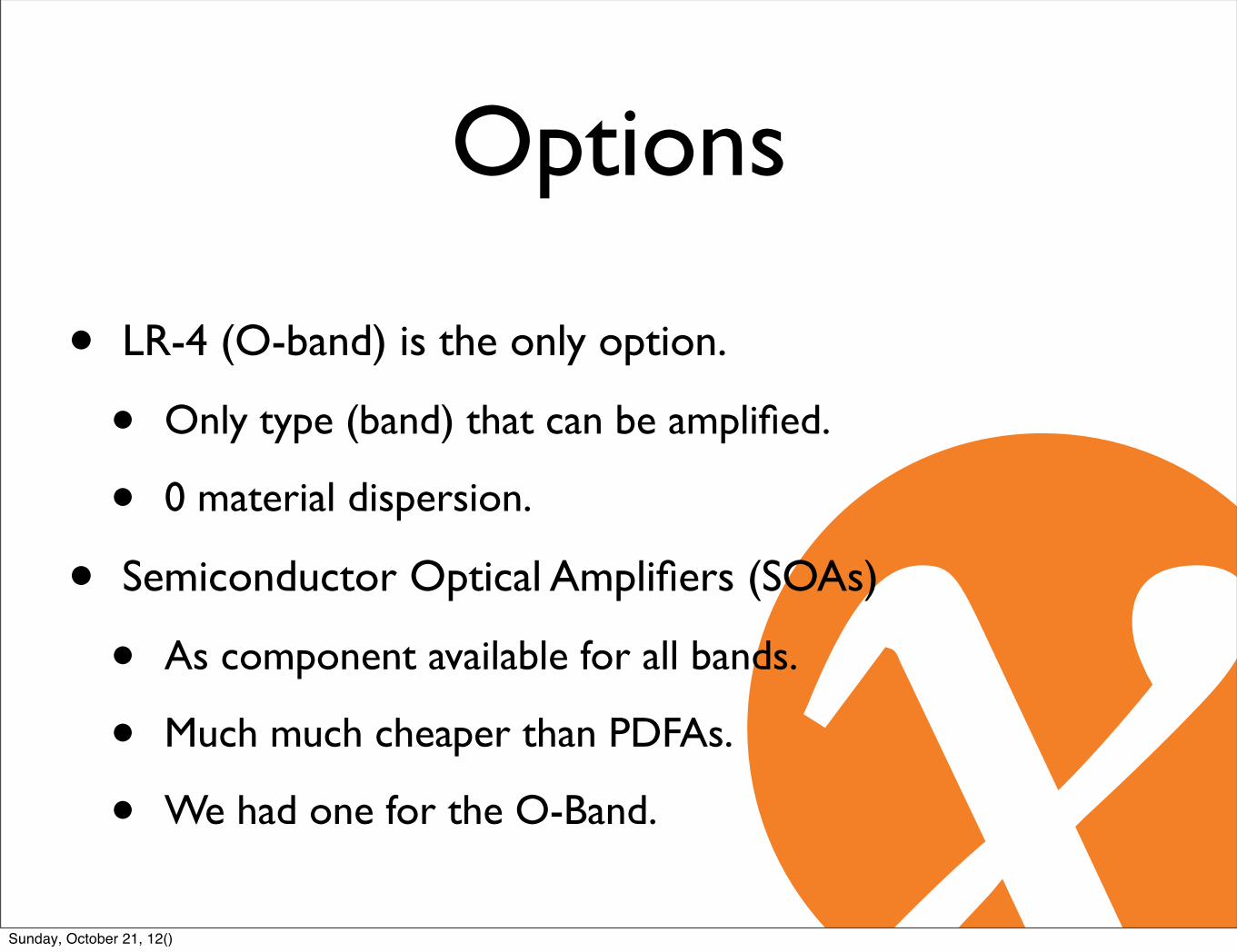
• LR-4 (O-band) is the only option.
• Only type (band) that can be amplified.
• 0 material dispersion.
• Semiconductor Optical Amplifiers (SOAs)
• As component available for all bands.
• Much much cheaper than PDFAs.
• We had one for the O-Band.
Options
Sunday, October 21, 12()

Experiment
Anritsu MD1260A
100G-LR4CFP SOA
14.35km
Loop
Sunday, October 21, 12()

db
10 15 20 25 30 35 km
-60
-50
-40
-30
-20
-10
0
0
Sunday, October 21, 12()
db
10 15 20 25 30 35 km
-60
-50
-40
-30
-20
-10
0
0
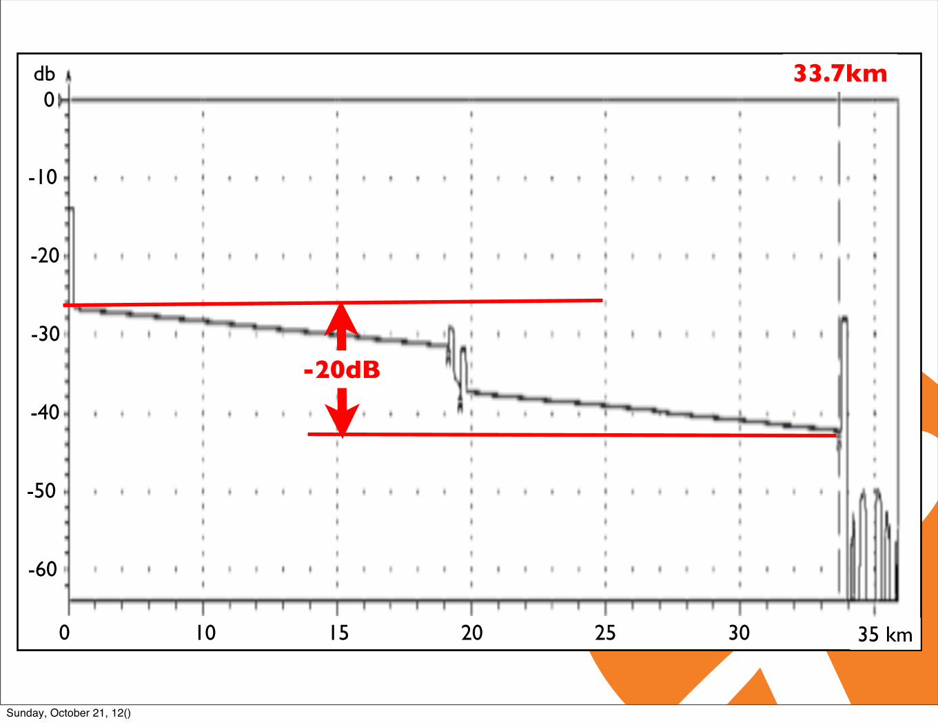
33.7km
-20dB
Sunday, October 21, 12()

db
10 15 20 25 30 35 km
-60
-50
-40
-30
-20
-10
0
0
33.7km
-6.7dB
Sunday, October 21, 12()

db
10 15 20 25 30 35 km
-60
-50
-40
-30
-20
-10
0
0
33.7km
Sunday, October 21, 12()
Sunday, October 21, 12()

-5.5dB
Sunday, October 21, 12()
• 6 trillion, 500 billion frames(6,500,000,000,000)
• Receives, all - 2(6,499,999,999,998)
Result
Sunday, October 21, 12()
Conclusions• Doped Fibre Amplifiers only suitable for O-band.
• PDFA
• Semiconductor Optical Amplifier.
• Seems to work well for the O-band.
• No ready made appliance (Just components and evaluation boards or lab equipment).
Sunday, October 21, 12()

Agenda• AMS-IX
• 100Gbit/s technology
• Problem statement
• Optical Amplifier development
• Metro DWDM equipment
• Production results
Sunday, October 21, 12()

Next steps• No SOA appliances (November 2011).
• Started to work with vendors and design bureaus to get that changed.
• 40km optics might be around the corner.
• Q4 2012... from one vendor...
• Electrical power budget might be a problem.
Sunday, October 21, 12()
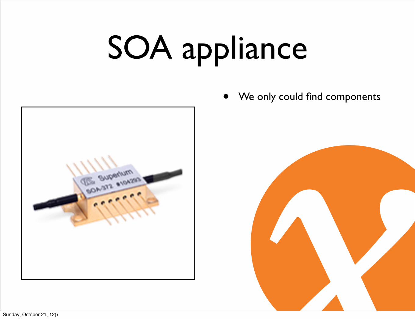
SOA appliance• We only could find components
Sunday, October 21, 12()
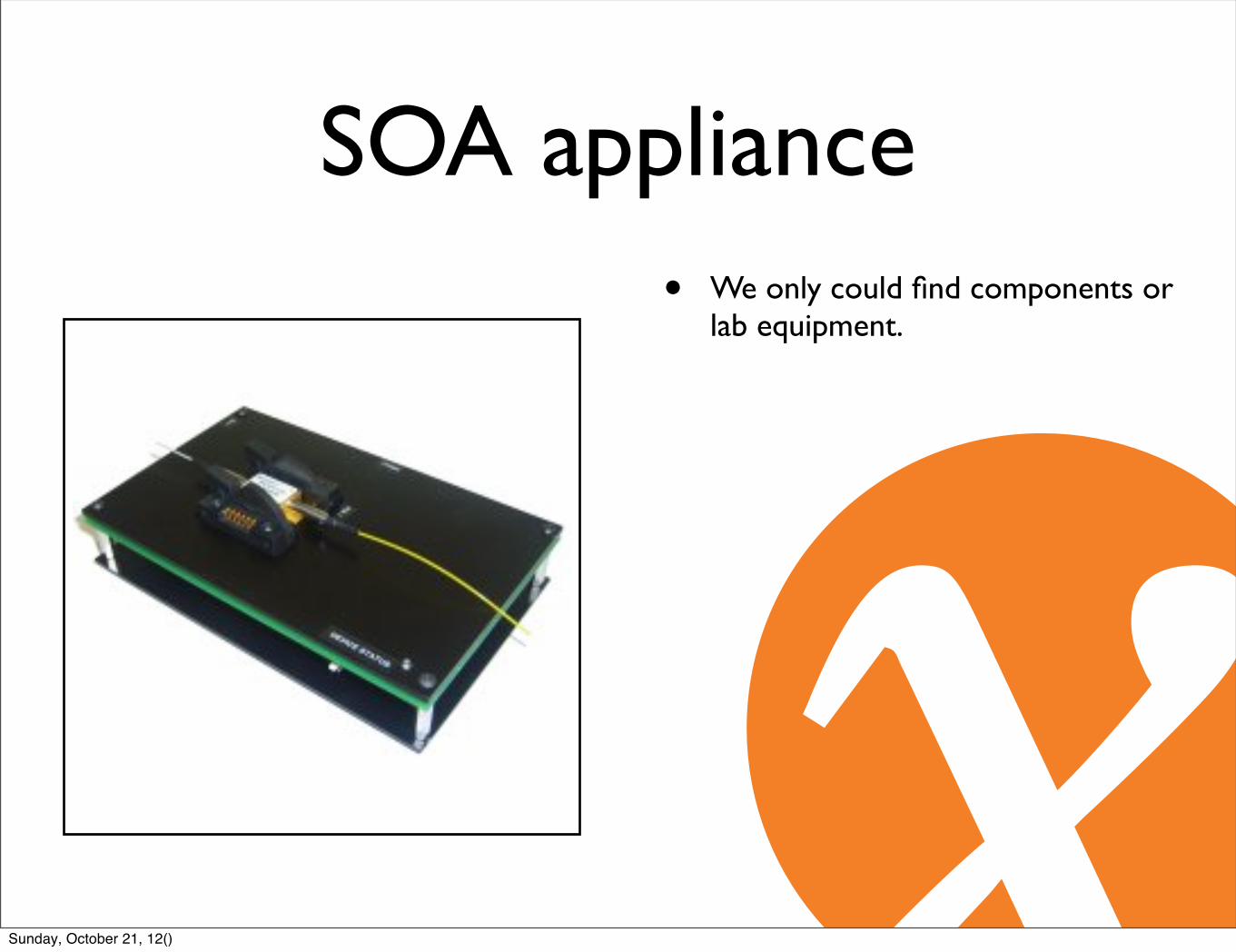
SOA appliance• We only could find components or
lab equipment.
Sunday, October 21, 12()

SOA appliance• We only could find components or
lab equipment.
• What is in that component?
Sunday, October 21, 12()

SOA appliance• We only could find components or
lab equipment.
• What is in that component?
• SOA consist of three parts.
• Laser
• Peltier element (TEC)
• NTC (temperature sensor)
TEC+
TEC-
NTC
NTC LaserA K
Sunday, October 21, 12()
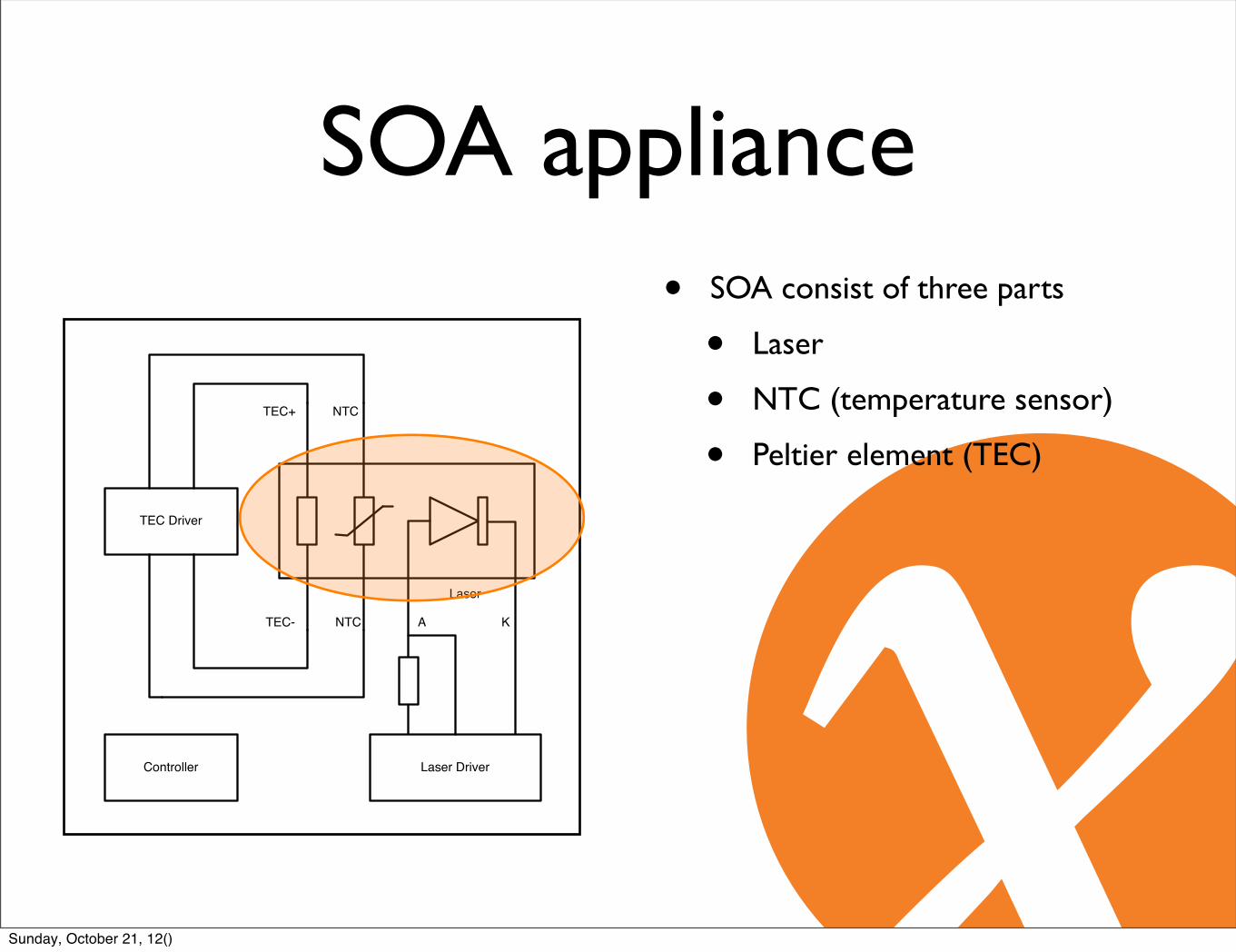
SOA appliance• SOA consist of three parts
• Laser
• NTC (temperature sensor)
• Peltier element (TEC)
TEC+
TEC-
NTC
NTC
Laser
A K
TEC Driver
Laser DriverController
Sunday, October 21, 12()
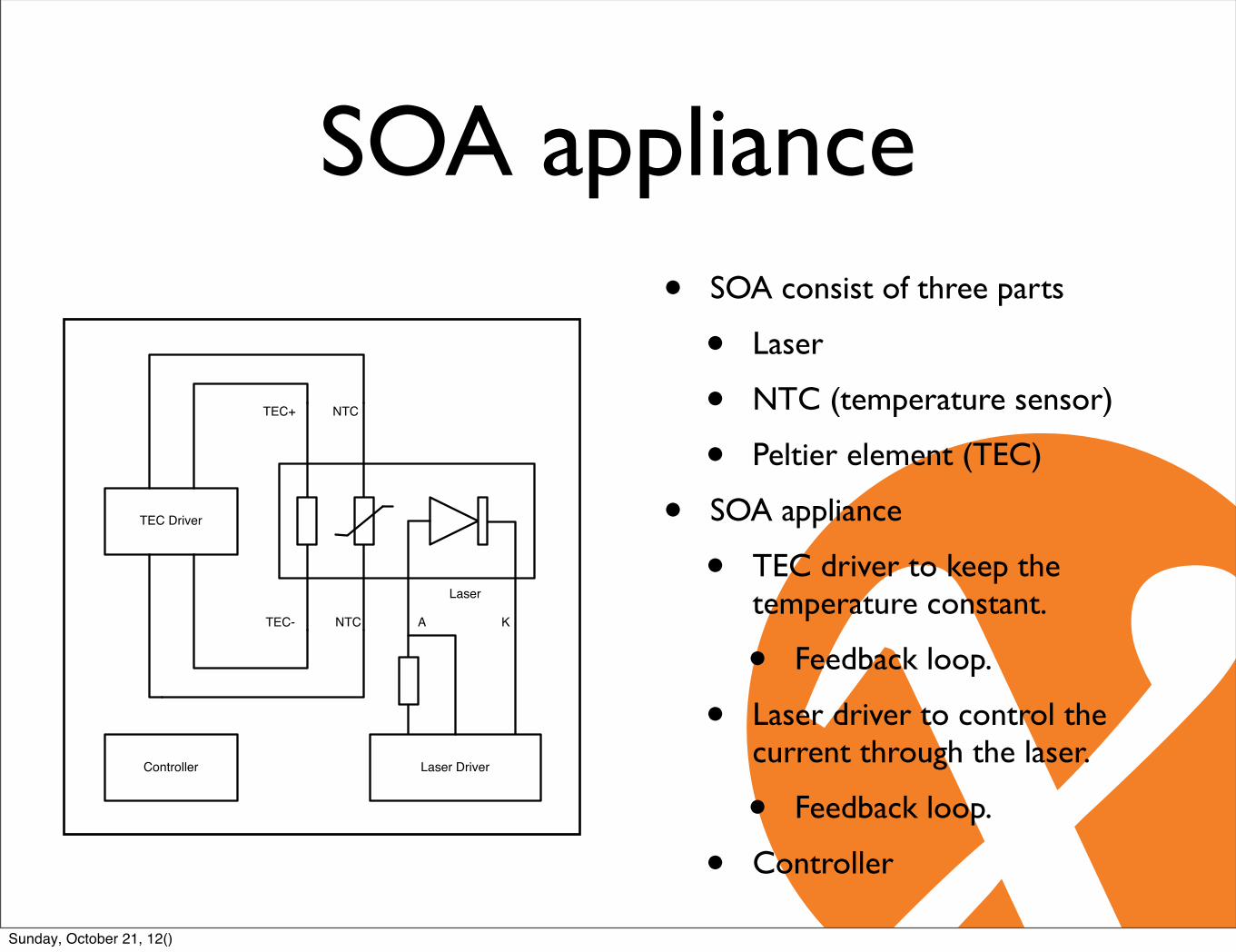
SOA appliance• SOA consist of three parts
• Laser
• NTC (temperature sensor)
• Peltier element (TEC)
• SOA appliance
• TEC driver to keep the temperature constant.
• Feedback loop.
• Laser driver to control the current through the laser.
• Feedback loop.
• Controller
TEC+
TEC-
NTC
NTC
Laser
A K
TEC Driver
Laser DriverController
Sunday, October 21, 12()
SOA appliances
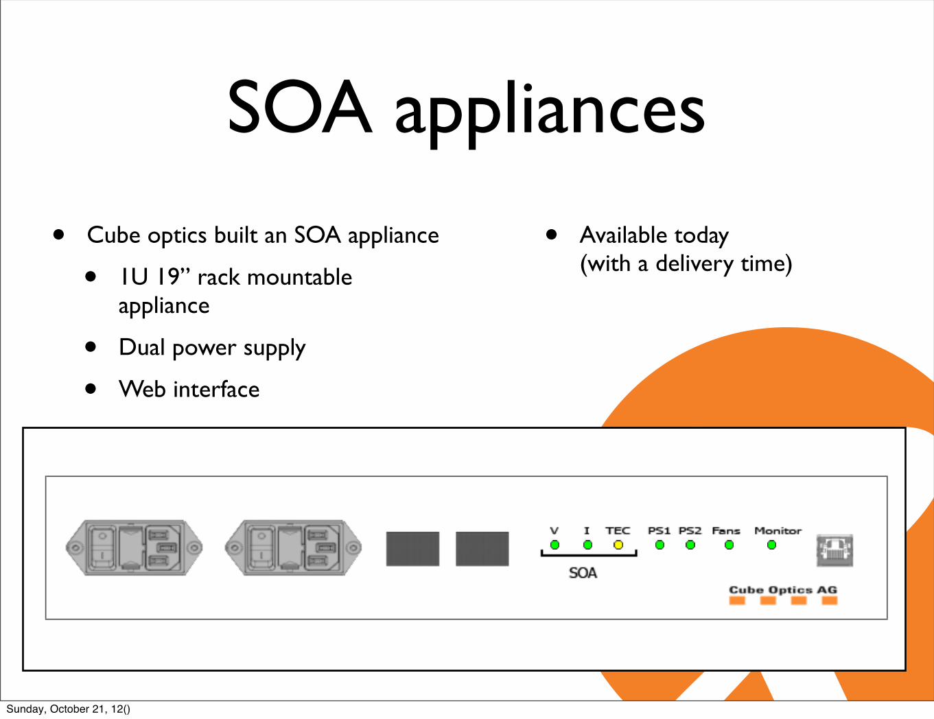
• Cube optics built an SOA appliance
• 1U 19” rack mountable appliance
• Dual power supply
• Web interface
• Available today (with a delivery time)
General Control Alarms
Inline SOA Unit : SAO20i 09P052
Status Information
Chip Current: 58 mA
Chip Current Setpoint: 60 mA
Temperature: 25.1 ºC
Temperature Setpoint: 25.0 ºC
Device Information
Serial Number: 12041143030002504-09P052
Cube Optics AG
System view Management settings About Logout
Cube Optics AG - TC-WMT http://amplifix.noc.ams-ix.net/index.php
1 of 1 5/10/12 10:09 AM
Sunday, October 21, 12()

SOA appliances• SnootLab
• 3U for a rack of 8 SOAs
• Covega or Amphotonics (Kamelian)
• Dual power supply
• SNMP interface
• Open Hardware
Sunday, October 21, 12()
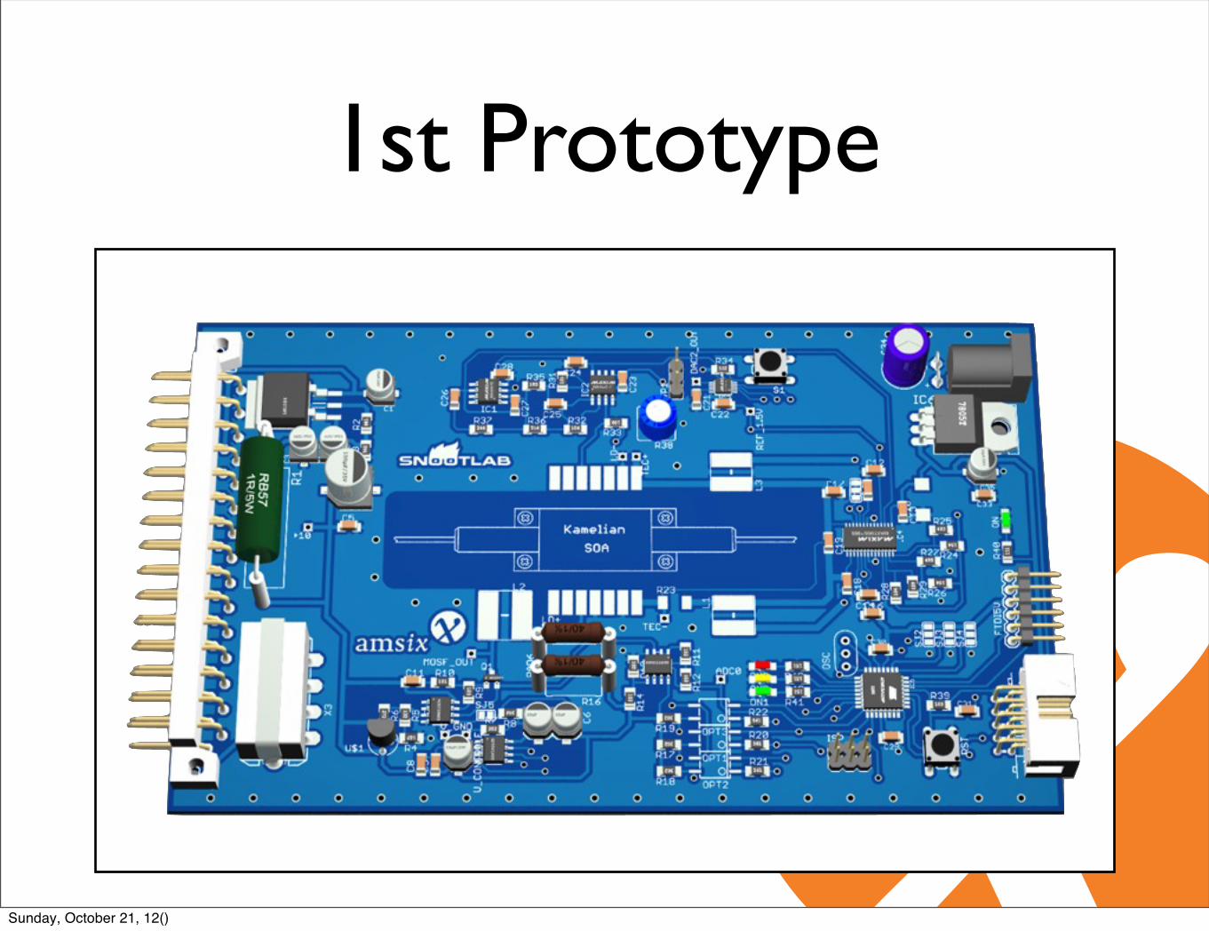
1st Prototype
Sunday, October 21, 12()
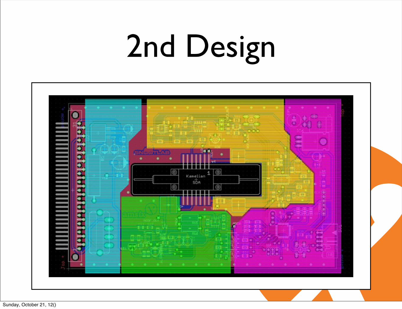
2nd Design
Sunday, October 21, 12()
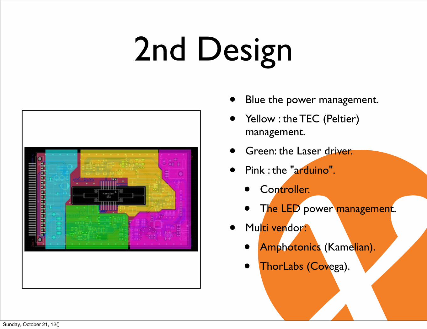
2nd Design• Blue the power management.
• Yellow : the TEC (Peltier) management.
• Green: the Laser driver.
• Pink : the "arduino".
• Controller.
• The LED power management.
• Multi vendor:
• Amphotonics (Kamelian).
• ThorLabs (Covega).
Sunday, October 21, 12()
Test results• Cube optics
• Error free over 22.6 km over 96 hours.
• SnootLabs
• Error free over 22.6 km over 36 hours.
• Shorter test window.
• This is suitable for most of our needs.
Sunday, October 21, 12()

Test results• Not error free over 45 km.
• Both Cube optics and SnootLab’s 1st prototype.
• Might be too long.
• Dispersion?
• Extinction ratio
• Ratio between 0 and 1 levels.
• Amplifier might not amplify these levels equally.
• Noise?
Sunday, October 21, 12()

Noise• Amplified Spontaneous Emission
(ASE)
REC31681 SAO20i 01P082 Default IP: 192.168.0.91 ASE spectrum
Sunday, October 21, 12()

Noise• 100G-LR receivers
• LAN WDM filter in the receiver drops most of the noise spectrum.
10x10Gbit/s 4x25Gbit/s
electrical optical
TEC
PINPINPINPIN
1:4
TIATIATIATIA
DMLDMLDMLDML
4:1
LDLDLDLD
Control
10:4
Sunday, October 21, 12()

Noise• Amplified Spontaneous Emission
(ASE)
• LAN WDM filter in the receiver drops most of the noise spectrum.
• Noise should be suppressed by 40dB to the signal.
REC31681 SAO20i 01P082 Default IP: 192.168.0.91 ASE spectrum
Sunday, October 21, 12()

Extinction ratio• Difference between 0 and 1 level.
Sunday, October 21, 12()
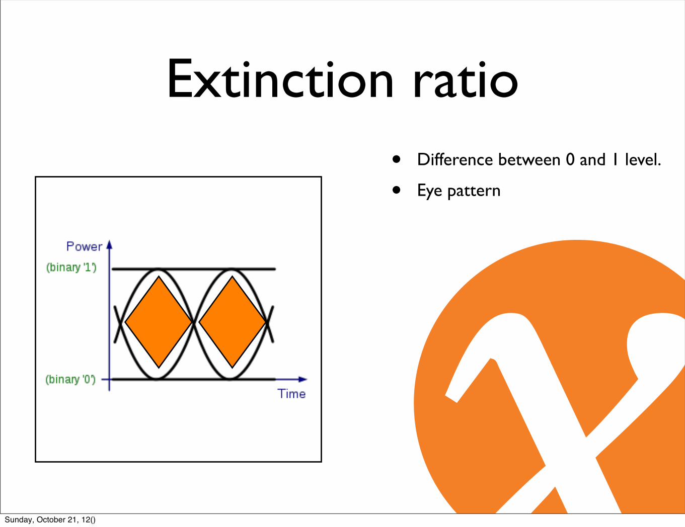
Extinction ratio• Difference between 0 and 1 level.
• Eye pattern
Sunday, October 21, 12()
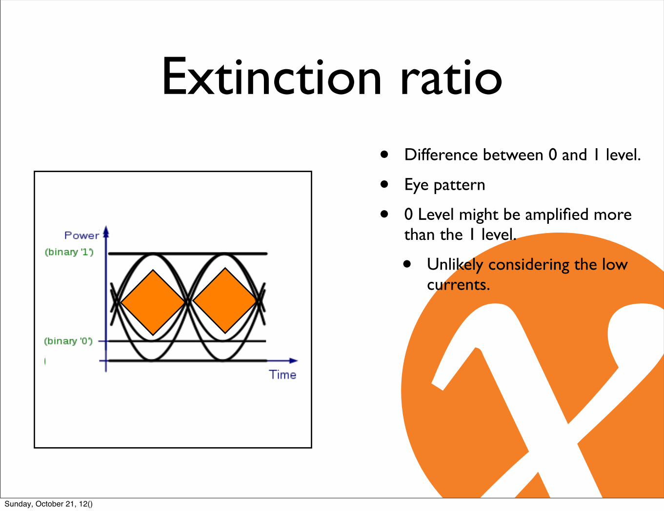
Extinction ratio• Difference between 0 and 1 level.
• Eye pattern
• 0 Level might be amplified more than the 1 level.
• Unlikely considering the low currents.
Sunday, October 21, 12()
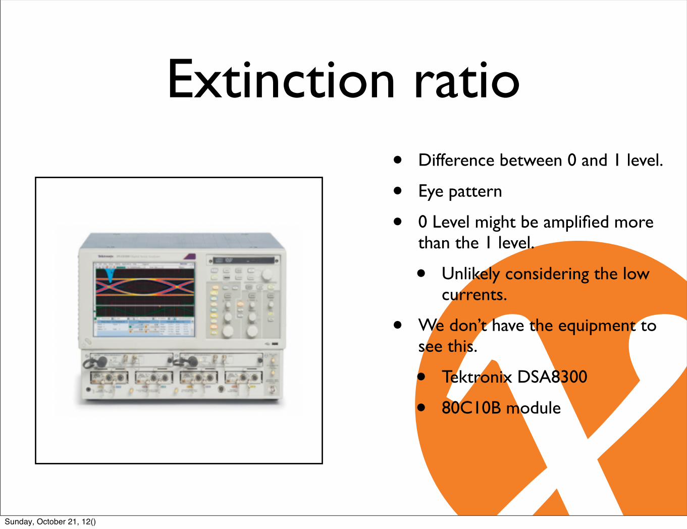
Extinction ratio• Difference between 0 and 1 level.
• Eye pattern
• 0 Level might be amplified more than the 1 level.
• Unlikely considering the low currents.
• We don’t have the equipment to see this.
• Tektronix DSA8300
• 80C10B module
Sunday, October 21, 12()
Conclusion• SOA and PDFA
• Certainly suitable for ~ 25km ranges
• Errors on 45km
• Not sure where they come from yet.
• Transmission equipment from ADVA, MRV, etc
Sunday, October 21, 12()

Agenda• AMS-IX
• 100Gbit/s technology
• Problem statement
• Optical Amplification
• Metro DWDM equipment
• Production results
Sunday, October 21, 12()
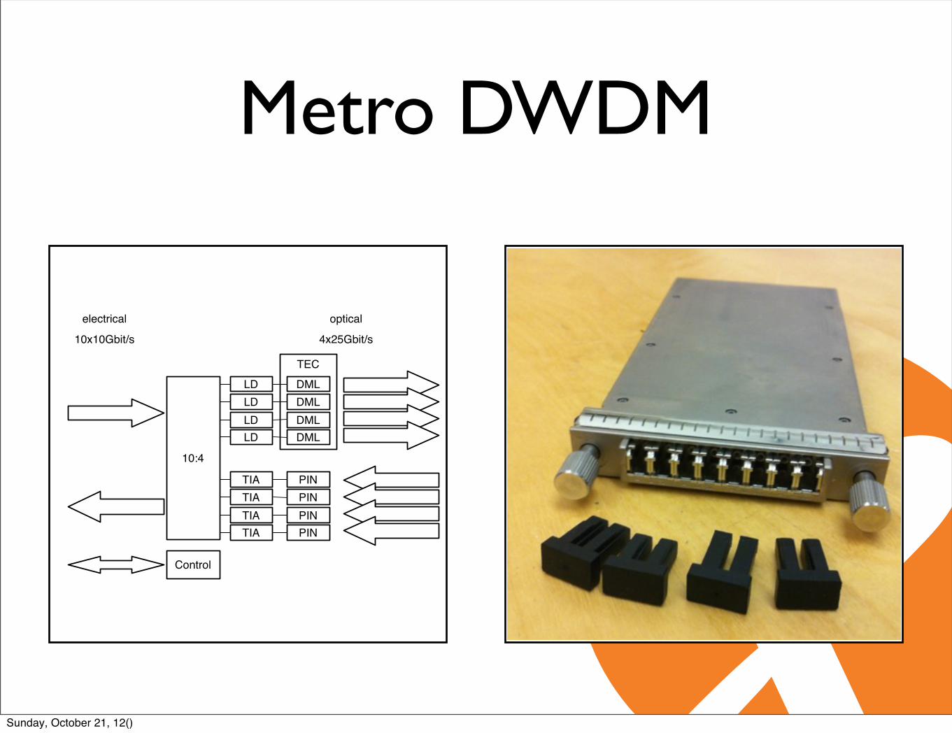
Metro DWDM
10x10Gbit/s 4x25Gbit/s
electrical optical
TEC
PINPINPINPIN
1:4
TIATIATIATIA
DMLDMLDMLDML
4:1
LDLDLDLD
Control
10:4
Sunday, October 21, 12()
Metro DWDM
10x10Gbit/s 4x25Gbit/s
electrical optical
TEC
PINPINPINPIN
TIATIATIATIA
DMLDMLDMLDML
LDLDLDLD
Control
10:4
Sunday, October 21, 12()
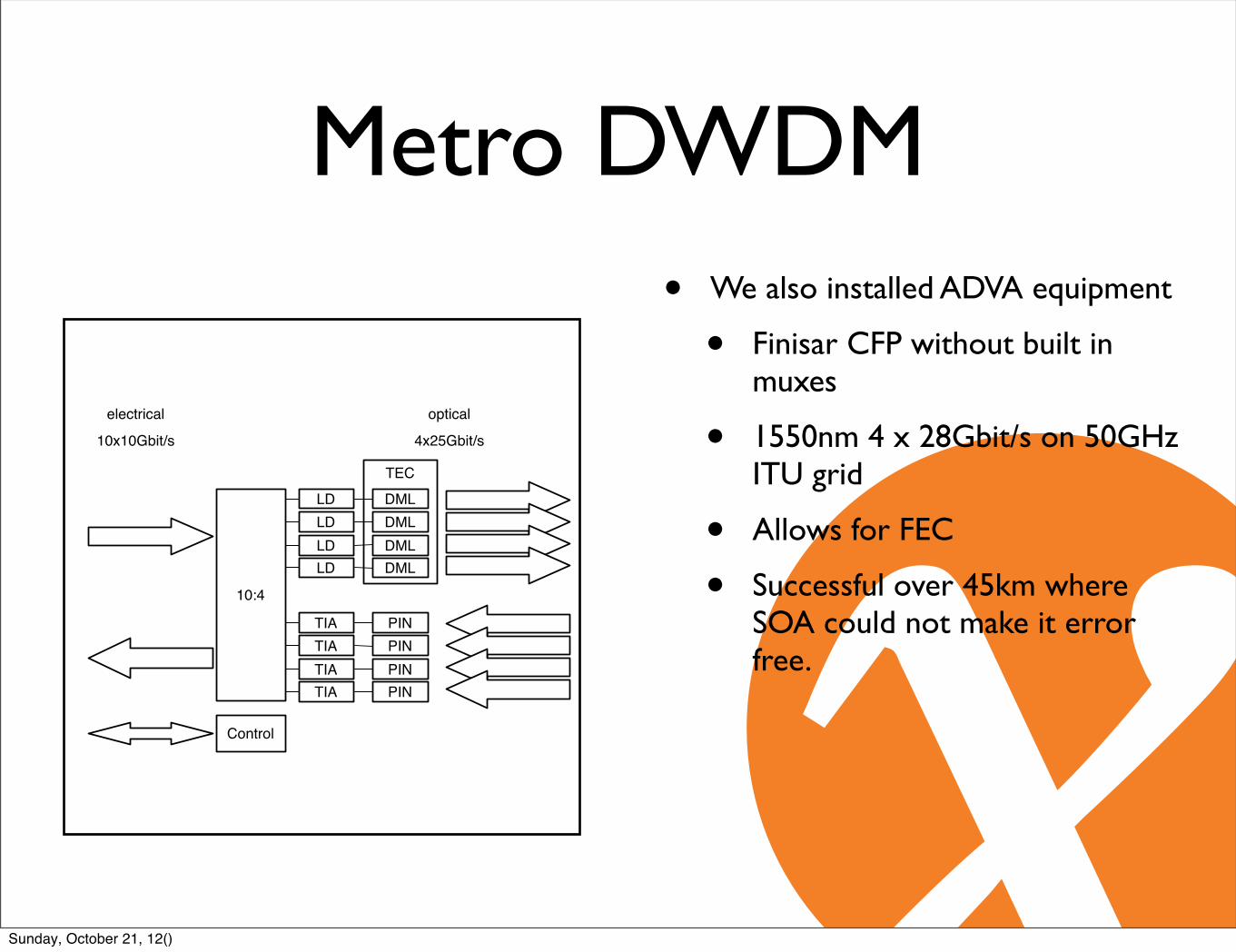
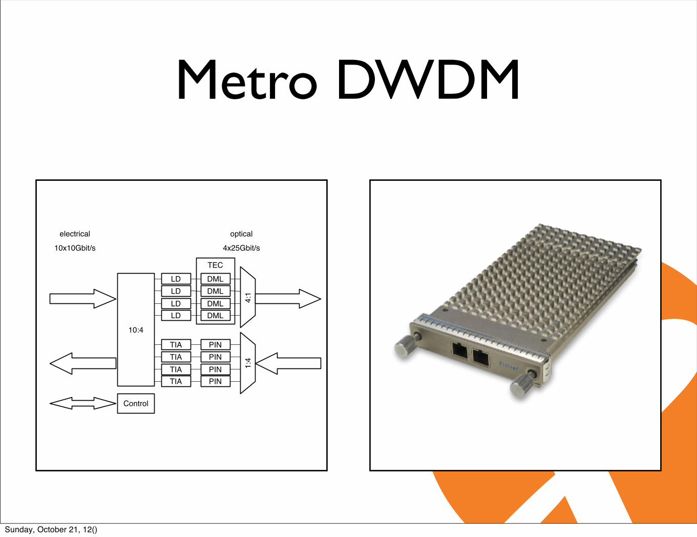
Metro DWDM• We also installed ADVA equipment
• Finisar CFP without built in muxes
• 1550nm 4 x 28Gbit/s on 50GHz ITU grid
• Allows for FEC
• Successful over 45km where SOA could not make it error free.
10x10Gbit/s 4x25Gbit/s
electrical optical
TEC
PINPINPINPIN
TIATIATIATIA
DMLDMLDMLDML
LDLDLDLD
Control
10:4
Sunday, October 21, 12()

Sunday, October 21, 12()

Agenda• AMS-IX
• 100Gbit/s technology
• Problem statement
• Optical Amplification
• Metro DWDM equipment
• Production results
Sunday, October 21, 12()
Map data ©2012 Google -
To see all the details that are visible on thescreen, use the "Print" link next to the map.
AMS-IX locations - Google Maps https://maps.google.com/
1 of 2 7/4/12(27) 5:12 PM
32km22km
Sunday, October 21, 12()
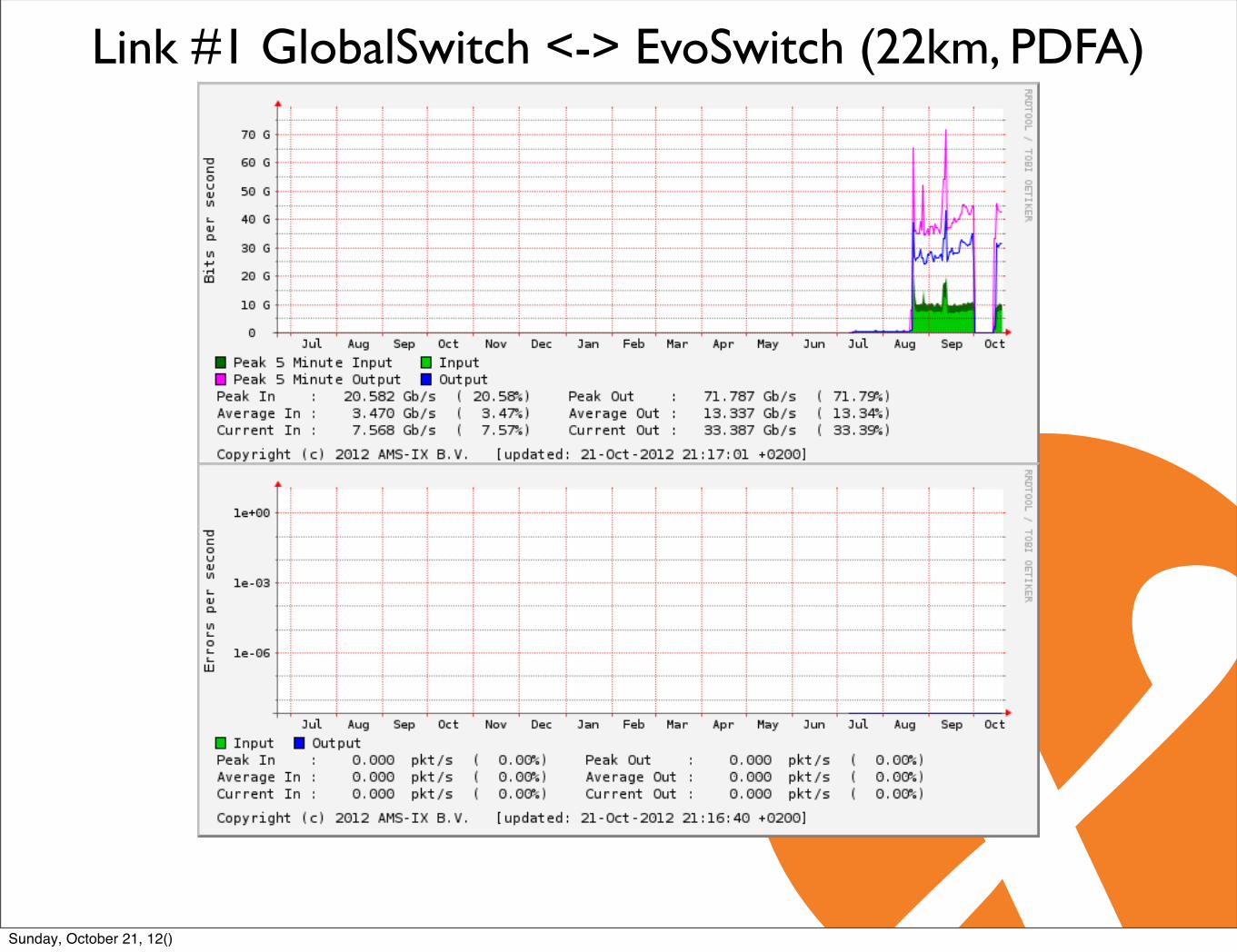
Link #1 GlobalSwitch <-> EvoSwitch (22km, PDFA)
Sunday, October 21, 12()

Link #2 GlobalSwitch <-> EvoSwitch (22km, SOA)
Sunday, October 21, 12()

Link #1 euNetworks <-> EvoSwitch (32km, SOA)
Sunday, October 21, 12()
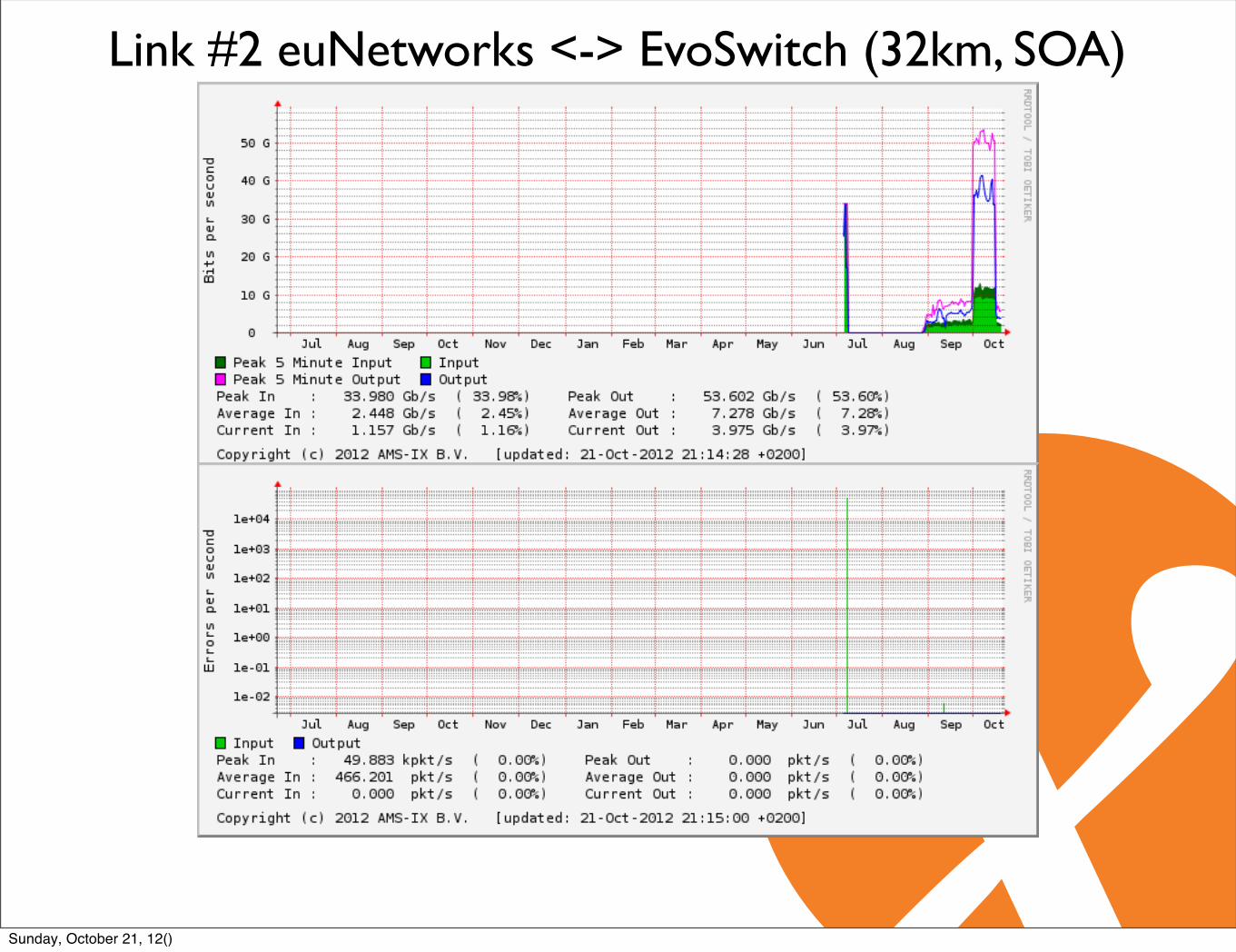
Link #2 euNetworks <-> EvoSwitch (32km, SOA)
Sunday, October 21, 12()
Production results• SOA
• 32km and 22km.
• Errors while tuning in.
• Not plug and play technology.
• No to a few errors while in production.
Sunday, October 21, 12()

EndComments & Questions
Sunday, October 21, 12()
Recommended