Experimental and Numerical Investigation of AirRadiation in Superorbital Expanding Flow
Han Wei 1 Richard G. Morgan 1 Timothy J. McIntyre1
Aaron M. Brandis 2 Christopher O. Johnston 3
1Centre for Hypersonics, the University of Queensland
2AMA at NASA Ames Research Center
3NASA Langley Research Center
9th June 2017
https://ntrs.nasa.gov/search.jsp?R=20170009879 2018-07-06T17:22:08+00:00Z
Outline
1 Introduction
2 Experimental Campaign
3 Numerical Simulation
4 Results and AnalysisFlow EstablishmentVUV Spectra
5 Conclusions
Han Wei Centre for Hypersonics 1 / 44
Outline
1 Introduction
2 Experimental Campaign
3 Numerical Simulation
4 Results and AnalysisFlow EstablishmentVUV Spectra
5 Conclusions
Han Wei Centre for Hypersonics 1 / 44
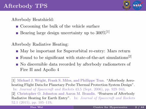
Afterbody TPS
Afterbody Heatshield:
Cocooning the bulk of the vehicle surface
Bearing large design uncertainty up to 300%[1]
Afterbody Radiative Heating:
May be important for Superorbital re-entry: Mars return
Found to be significant with state-of-the-art simulations[2]
No discernible data recorded by afterbody radiometers ofFire II and Apollo 4
[1] Michael J. Wright, Frank S. Milos, and Phillippe Tran. “Afterbody Aero-heating Flight Data for Planetary Probe Thermal Protection System Design”.In: Journal of Spacecraft and Rockets 43.5 (Sept. 2006), pp. 929–943.
[2] Christopher O. Johnston and Aaron M. Brandis. “Features of AfterbodyRadiative Heating for Earth Entry”. In: Journal of Spacecraft and Rockets52.1 (2015), pp. 105–119.
Han Wei Centre for Hypersonics 2 / 44
Post-mission Analyses
Wright et al.[3] achieved excellent agreement with Fire IIforebody convective heating data, but the afterbodyexperimental data were a factor of two higher than thenoncatalytic predictions
Johnston and Brandis[4] re-examined the FIRE IIafterbody measurements and questioned the analysis of theradiometer data. Major sources of model uncertainties forafterbody radiation were identified: the rate coefficient forthe three-body electron-ion recombination reaction, theescape factors on collisional-radiative modelling, and theimpact of forebody ablation.
[3] Michael Wright, Mark Loomis, and Periklis Papadopoulos. “AerothermalAnalysis of the Project Fire II Afterbody Flow”. In: Journal of Thermo-physics and Heat Transfer 17.2 (2003), pp. 240–249.[4] Christopher O. Johnston and Aaron M. Brandis. “Features of AfterbodyRadiative Heating for Earth Entry”. In: Journal of Spacecraft and Rockets52.1 (2015), pp. 105–119.
Han Wei Centre for Hypersonics 3 / 44
Recent Advancements in Numerical Models
Johnston and Panesi[5]: treating nitrogen atoms of differentgrouped electronic levels as individual species in the flowfield model, coupling radiative transition rates to thespecies continuity equations, adopting a ray-tracingapproach in radiation transport calculation and developinga nonequilibrium model for NO
Lopez et al.[6] improved the non-Boltzmann modelling ofnitrogen by adopting a state-to-state description ofgrouped electronic states
[5] Christopher O. Johnston and Marco Panesi. “Advancements in After-body Radiative Heating Simulations for Earth Entry”. In: 46th AIAAThermophysics Conference. AIAA Aviation. American Institute of Aero-nautics and Astronautics, June 13, 2016.[6] Bruno Lopez, Christopher O. Johnston, and Marco Panesi. “ImprovedNon-Boltzmann Modeling for Nitrogen Atoms”. In: 46th AIAA Thermo-physics Conference. AIAA Aviation. American Institute of Aeronautics andAstronautics, June 10, 2016.
Han Wei Centre for Hypersonics 4 / 44
Recent Advancements in Numerical Models
West et al.[7] performed sensitivity analysis and uncertaintyquantification of afterbody radiation for Stardust at peakafterbody radiative heating conditions. Four variables werefound to contribute to nearly 95% of the uncertainty: theelectronic-impact excitation rate for N between levels 2 and5 and the rates of three chemical reactions that affect thenumber densities of N, N+, O and O+.
Validation data of afterbody radiation is in high demand,particularly in the VUV wavelength range
[7] Thomas K. West IV, Christopher O. Johnston, and Serhat Hosder.“Uncertainty and Sensitivity Analysis of Afterbody Radiative Heating Pre-dictions for Earth Entry”. In: 54th AIAA Aerospace Sciences Meeting.AIAA SciTech. American Institute of Aeronautics and Astronautics, Jan. 2,2016.
Han Wei Centre for Hypersonics 5 / 44
Outline
1 Introduction
2 Experimental Campaign
3 Numerical Simulation
4 Results and AnalysisFlow EstablishmentVUV Spectra
5 Conclusions
Han Wei Centre for Hypersonics 5 / 44
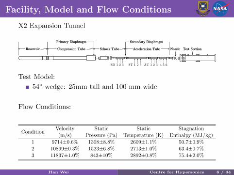
Facility, Model and Flow Conditions
X2 Expansion Tunnel
Acceleration TubeReservoir Compression Tube Schock Tube Test SectionNozzle
Primary Diaphragm Secondary Diaphragm
SD 1 2 3 ST 1 2 3 AT 1 2 3 4 5 6
Acceleration TubeReservoir Compression Tube Schock Tube Test SectionNozzle
Primary Diaphragm Secondary Diaphragm
Test Model:
54◦ wedge: 25mm tall and 100 mm wide
Flow Conditions:
ConditionVelocity(m/s)
StaticPressure (Pa)
StaticTemperature (K)
StagnationEnthalpy (MJ/kg)
1 9714±0.6% 1308±8.8% 2609±1.1% 50.7±0.9%2 10899±0.3% 1523±6.8% 2713±1.0% 63.4±0.7%3 11837±1.0% 843±10% 2892±0.8% 75.4±2.0%
Han Wei Centre for Hypersonics 6 / 44
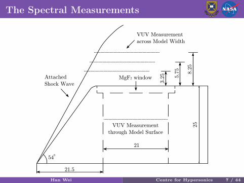
The Spectral Measurements
21.5
3.2
5 5.7
5
8.2
5
MgF2 window
VUV Measurement
across Model Width
VUV Measurement
through Model Surface
21
Attached
Shock Wave
54
25
Han Wei Centre for Hypersonics 7 / 44
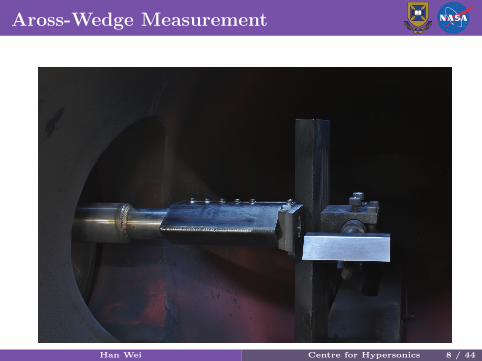
Aross-Wedge Measurement
Han Wei Centre for Hypersonics 8 / 44
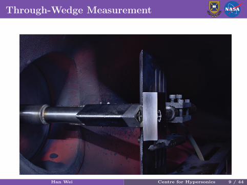
Through-Wedge Measurement
Han Wei Centre for Hypersonics 9 / 44
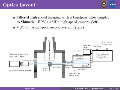
Optics Layout
Filtered high speed imaging with a bandpass filter coupledto Shimadzu HPV-1 1MHz high speed camera (left)
VUV emission spectroscopy system (right)
Flow
Andor iStar
DH340T
ICCD Camera
Flat Mirror
SlitAperture
Concave Mirror
f=500mm
Nozzle Centreline
MgF2 WindowWedge
Model
McPherson Nova 225
1m Focal Length
VUV Spectrometer
BellowsOptics Box
Pfeiffer TPG 261
Vacuum Gauge
Pfeiffer TPG 361
Vacuum Gauge
Shimadzu HPV-1 1MHz
High Speed Camera
Bandpass Filter
Nikkor Micro 200mm F/4D IF-ED
Pump Flange
Pump Flange
Han Wei Centre for Hypersonics 10 / 44
Outline
1 Introduction
2 Experimental Campaign
3 Numerical Simulation
4 Results and AnalysisFlow EstablishmentVUV Spectra
5 Conclusions
Han Wei Centre for Hypersonics 10 / 44
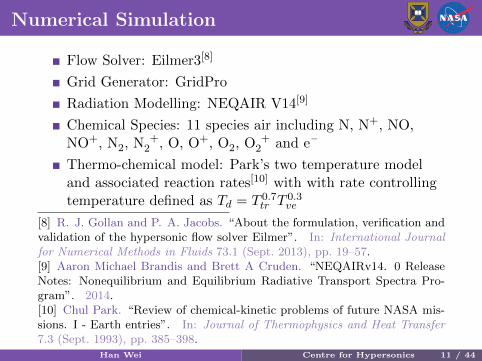
Numerical Simulation
Flow Solver: Eilmer3[8]
Grid Generator: GridPro
Radiation Modelling: NEQAIR V14[9]
Chemical Species: 11 species air including N, N+, NO,NO+, N2, N +
2 , O, O+, O2, O +2 and e–
Thermo-chemical model: Park’s two temperature modeland associated reaction rates[10] with with rate controllingtemperature defined as Td = T 0.7
tr T 0.3ve
[8] R. J. Gollan and P. A. Jacobs. “About the formulation, verification andvalidation of the hypersonic flow solver Eilmer”. In: International Journalfor Numerical Methods in Fluids 73.1 (Sept. 2013), pp. 19–57.[9] Aaron Michael Brandis and Brett A Cruden. “NEQAIRv14. 0 ReleaseNotes: Nonequilibrium and Equilibrium Radiative Transport Spectra Pro-gram”. 2014.[10] Chul Park. “Review of chemical-kinetic problems of future NASA mis-sions. I - Earth entries”. In: Journal of Thermophysics and Heat Transfer7.3 (Sept. 1993), pp. 385–398.
Han Wei Centre for Hypersonics 11 / 44
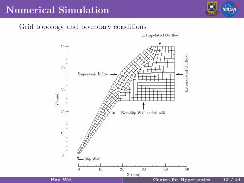
Numerical Simulation
Grid topology and boundary conditions
0 10 20 30 40 50
X (mm)
0
20
10
30
40
50
Y(m
m)
Supersonic Inflow
Slip Wall
Non-Slip Wall at 298.15K
Extr
apola
ted O
utf
low
Extrapolated Outflow
Han Wei Centre for Hypersonics 12 / 44
Outline
1 Introduction
2 Experimental Campaign
3 Numerical Simulation
4 Results and AnalysisFlow EstablishmentVUV Spectra
5 Conclusions
Han Wei Centre for Hypersonics 12 / 44
Outline
1 Introduction
2 Experimental Campaign
3 Numerical Simulation
4 Results and AnalysisFlow EstablishmentVUV Spectra
5 Conclusions
Han Wei Centre for Hypersonics 12 / 44
Flow Establishment
High speed video through Thorlabs FBH780-10 bandpass filterat 0.5 MHz
Han Wei Centre for Hypersonics 13 / 44
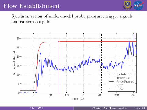
Flow Establishment
Synchronisation of under-model probe pressure, trigger signalsand camera outputs
0 50 100 150 200 250 300
Time (µs)
0
5
10
15
20
25
30
Nor
mal
ised
Ou
tpu
t
Photodiode
Trigger Box
Probe Pressure
ICCD
HPV-1
Han Wei Centre for Hypersonics 14 / 44
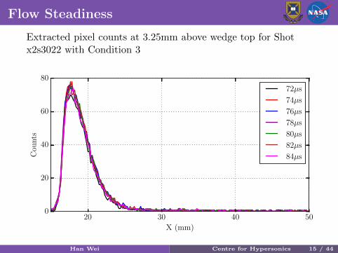
Flow Steadiness
Extracted pixel counts at 3.25mm above wedge top for Shotx2s3022 with Condition 3
20 30 40 50
X (mm)
0
20
40
60
80
Cou
nts
72µs
74µs
76µs
78µs
80µs
82µs
84µs
Han Wei Centre for Hypersonics 15 / 44
Outline
1 Introduction
2 Experimental Campaign
3 Numerical Simulation
4 Results and AnalysisFlow EstablishmentVUV Spectra
5 Conclusions
Han Wei Centre for Hypersonics 15 / 44
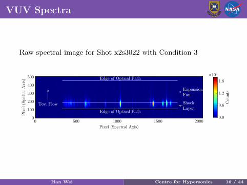
VUV Spectra
Raw spectral image for Shot x2s3022 with Condition 3
Test Flow
Edge of Optical Path
Edge of Optical Path
Shock
Layer
Expansion
Fan
Han Wei Centre for Hypersonics 16 / 44
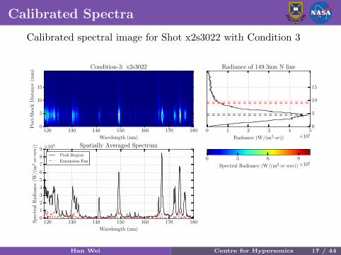
Calibrated Spectra
Calibrated spectral image for Shot x2s3022 with Condition 3
120 130 140 150 160 170 180
Wavelength (nm)
0
5
10
15
Pos
t-S
hock
Dis
tan
ce(m
m) Condition-3: x2s3022
0 1 2 3 4 5
Radiance (W/(m2·sr)) ×105
0
5
10
15
Radiance of 149.3nm N line
120 130 140 150 160 170 180
Wavelength (nm)
0
1
2
3
4
5
6
7
8
9
Sp
ectr
alR
adia
nce
(W/(
m2·sr·nm
)) ×105 Spatially Averaged Spectrum
Peak Region
Expansion Fan0 3 6 9
Spectral Radiance (W/(m2·sr·nm))×105
Han Wei Centre for Hypersonics 17 / 44
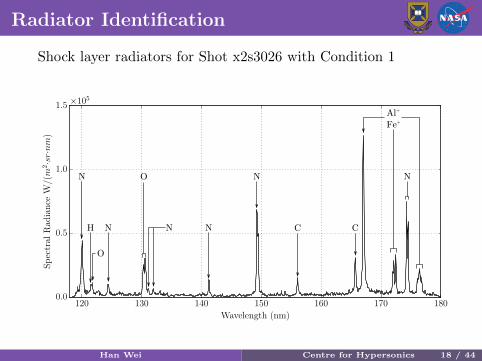
Radiator Identification
Shock layer radiators for Shot x2s3026 with Condition 1
N
N
NN
C CH N
Al+
Fe+
N
O
O
Han Wei Centre for Hypersonics 18 / 44
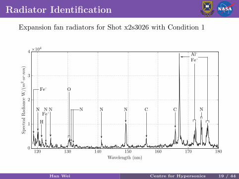
Radiator Identification
Expansion fan radiators for Shot x2s3026 with Condition 1
NN NN C C
H
N
Al+
Fe+
O
N
Fe+
NFe+
Han Wei Centre for Hypersonics 19 / 44
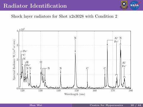
Radiator Identification
Shock layer radiators for Shot x2s3028 with Condition 2
C
N
N
N
N
C CN
Al+
Fe+
Fe+
N
H
N
OFe+
Al+
Fe+
Han Wei Centre for Hypersonics 20 / 44
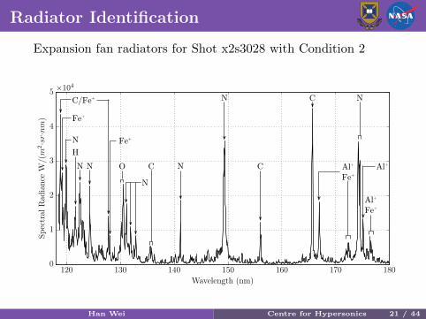
Radiator Identification
Expansion fan radiators for Shot x2s3028 with Condition 2
N
N
N
C
C
N
Fe+
N
H
N
O
C/Fe+
N Fe+
C Al+Al+
Fe+
Al+
Fe+
Han Wei Centre for Hypersonics 21 / 44
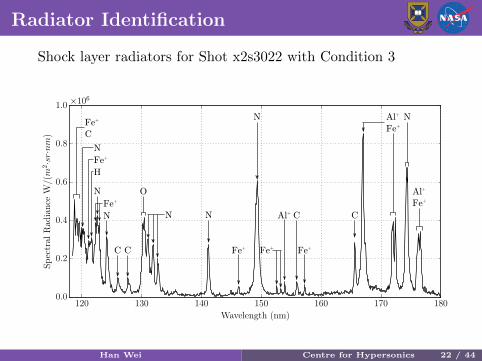
Radiator Identification
Shock layer radiators for Shot x2s3022 with Condition 3
N
N
N
N
N
C C
Al+
Fe+
C C
N
H
Fe+
C
N
Fe+
Al+
Fe+
O
Fe+
Fe+
Fe+
Al+
Fe+
Han Wei Centre for Hypersonics 22 / 44
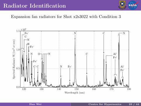
Radiator Identification
Expansion fan radiators for Shot x2s3022 with Condition 3
N
N
N
C
C
Al+
Fe+C C
N
H
Fe+
C
NO
Fe+
Fe+
Al+
Fe+N
Fe+
Han Wei Centre for Hypersonics 23 / 44
Radiator Identification
The level of contamination increases with flow enthalpy
The expansion fan spectra tend to be packed with moredistinguishable features of contaminants
C and Al+ can be stronger relative to N lines in theexpansion fan for certain conditions
Han Wei Centre for Hypersonics 24 / 44
Through-Wedge Spectra
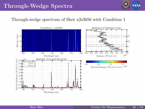
Through-wedge spectrum of Shot x2s3056 with Condition 1
120 130 140 150 160 170 180
Wavelength (nm)
0
5
10
15
Dis
tan
ce(m
m)
Condition-1: x2s3056
0.0 0.2 0.4 0.6 0.8 1.0 1.2 1.4 1.6
Radiance (W/(m2·sr)) ×103
0
5
10
15
Radiance of 149.3nm N line
120 130 140 150 160 170 180
Wavelength (nm)
0.0
0.5
1.0
1.5
2.0
2.5
3.0
3.5
4.0
4.5
Sp
ectr
alR
adia
nce
(W/(
m2·sr·nm
)) ×103 Spatially Averaged Spectrum
Region 1
Region 20.0 2.5 5.0 7.5
Spectral Radiance (W/(m2·sr·nm))×103
Han Wei Centre for Hypersonics 25 / 44

Through-Wedge Spectra
Through-wedge spectrum of Shot x2s3059 with Condition 2
120 130 140 150 160 170 180
Wavelength (nm)
0
5
10
15
Dis
tan
ce(m
m)
Condition-2: x2s3059
0.0 0.5 1.0 1.5 2.0 2.5
Radiance (W/(m2·sr)) ×104
0
5
10
15
Radiance of 149.3nm N line
120 130 140 150 160 170 180
Wavelength (nm)
0
1
2
3
4
5
Sp
ectr
alR
adia
nce
(W/(
m2·sr·nm
)) ×104 Spatially Averaged Spectrum
Region 1
Region 20 2 4 6
Spectral Radiance (W/(m2·sr·nm))×104
Han Wei Centre for Hypersonics 26 / 44
Through-Wedge Spectra
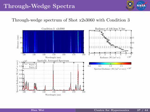
Through-wedge spectrum of Shot x2s3060 with Condition 3
120 130 140 150 160 170 180
Wavelength (nm)
0
5
10
15
Dis
tan
ce(m
m)
Condition-3: x2s3060
0 1 2 3 4 5 6 7 8
Radiance (W/(m2·sr)) ×104
0
5
10
15
Radiance of 149.3nm N line
120 130 140 150 160 170 180
Wavelength (nm)
0.0
0.2
0.4
0.6
0.8
1.0
1.2
1.4
Sp
ectr
alR
adia
nce
(W/(
m2·sr·nm
)) ×105 Spatially Averaged Spectrum
Region 1
Region 20.0 0.5 1.0 1.5
Spectral Radiance (W/(m2·sr·nm))×105
Han Wei Centre for Hypersonics 27 / 44
VUV Spectra vs Simulations
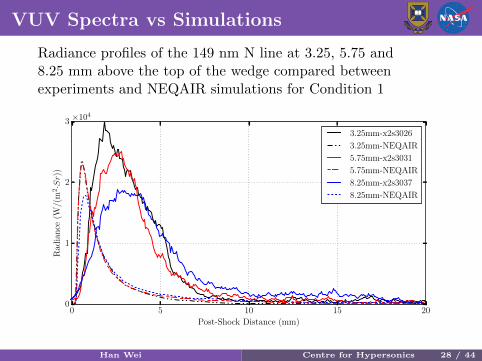
Radiance profiles of the 149 nm N line at 3.25, 5.75 and8.25 mm above the top of the wedge compared betweenexperiments and NEQAIR simulations for Condition 1
0 5 10 15 20
Post-Shock Distance (mm)
0
1
2
3
Rad
ian
ce(W
/(m
2·Sr)
)
×104
3.25mm-x2s3026
3.25mm-NEQAIR
5.75mm-x2s3031
5.75mm-NEQAIR
8.25mm-x2s3037
8.25mm-NEQAIR
Han Wei Centre for Hypersonics 28 / 44
VUV Spectra vs Simulations
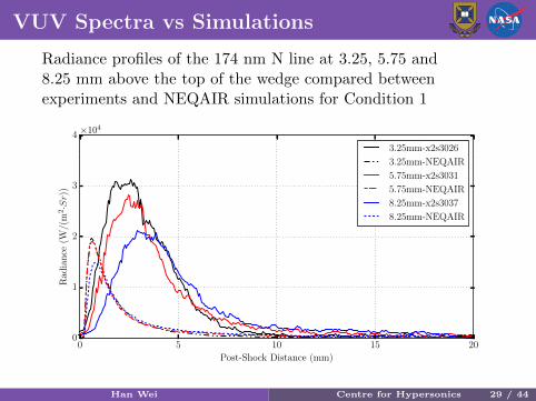
Radiance profiles of the 174 nm N line at 3.25, 5.75 and8.25 mm above the top of the wedge compared betweenexperiments and NEQAIR simulations for Condition 1
0 5 10 15 20
Post-Shock Distance (mm)
0
1
2
3
4
Rad
ian
ce(W
/(m
2·Sr)
)
×104
3.25mm-x2s3026
3.25mm-NEQAIR
5.75mm-x2s3031
5.75mm-NEQAIR
8.25mm-x2s3037
8.25mm-NEQAIR
Han Wei Centre for Hypersonics 29 / 44
VUV Spectra vs Simulations
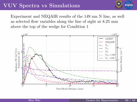
Experiment and NEQAIR results of the 149 nm N line, as wellas selected flow variables along the line of sight at 8.25 mmabove the top of the wedge for Condition 1
0 5 10 15 20
Post-Shock Distance (mm)
0
1
2
3
Rad
ian
ce(W
/(m
2·Sr)
)T
emp
erat
ure
(K)
×104
0
2
4
6
8
Nu
mb
erD
ensi
ty(c
m−
3)
×1017
x2s3037
NEQAIRTtr
Tve
NN
NN+×100
Ne−×100
Han Wei Centre for Hypersonics 30 / 44
VUV Spectra vs Simulations
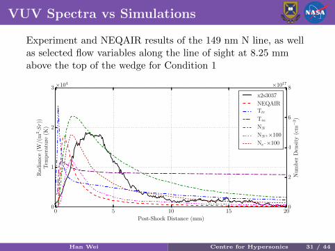
Experiment and NEQAIR results of the 149 nm N line, as wellas selected flow variables along the line of sight at 8.25 mmabove the top of the wedge for Condition 1
0 5 10 15 20
Post-Shock Distance (mm)
0
1
2
3
Rad
ian
ce(W
/(m
2·Sr)
)T
emp
erat
ure
(K)
×104
0
2
4
6
8
Nu
mb
erD
ensi
ty(c
m−
3)
×1017
x2s3037
NEQAIRTtr
Tve
NN
NN+×100
Ne−×100
Han Wei Centre for Hypersonics 31 / 44
VUV Spectra vs Simulations
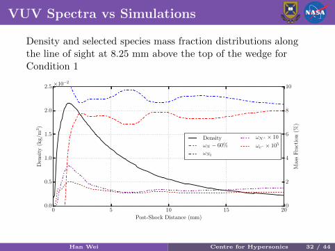
Density and selected species mass fraction distributions alongthe line of sight at 8.25 mm above the top of the wedge forCondition 1
0 5 10 15 20
Post-Shock Distance (mm)
0.0
0.5
1.0
1.5
2.0
2.5
Den
sity
(kg/
m3)
×10−2
0
2
4
6
8
10
Mas
sF
ract
ion
(%)
Density
ωN − 60%
ωN2
ωN+ × 10
ωe− × 105
Han Wei Centre for Hypersonics 32 / 44
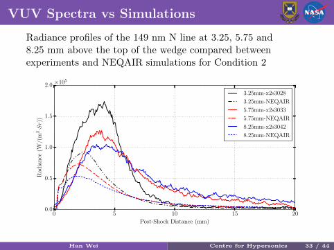
VUV Spectra vs Simulations
Radiance profiles of the 149 nm N line at 3.25, 5.75 and8.25 mm above the top of the wedge compared betweenexperiments and NEQAIR simulations for Condition 2
0 5 10 15 20
Post-Shock Distance (mm)
0.0
0.5
1.0
1.5
2.0
Rad
ian
ce(W
/(m
2·Sr)
)
×105
3.25mm-x2s3028
3.25mm-NEQAIR
5.75mm-x2s3033
5.75mm-NEQAIR
8.25mm-x2s3042
8.25mm-NEQAIR
Han Wei Centre for Hypersonics 33 / 44
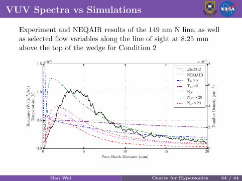
VUV Spectra vs Simulations
Experiment and NEQAIR results of the 149 nm N line, as wellas selected flow variables along the line of sight at 8.25 mmabove the top of the wedge for Condition 2
0 5 10 15 20
Post-Shock Distance (mm)
0.0
0.5
1.0
1.5
Rad
ian
ce(W
/(m
2·Sr)
)T
emp
erat
ure
(K)
×105
0
2
4
6
8
Nu
mb
erD
ensi
ty(c
m−
3)
×1017
x2s3042
NEQAIRTtr×5
Tve×5
NN
NN+×20
Ne+×20
Han Wei Centre for Hypersonics 34 / 44
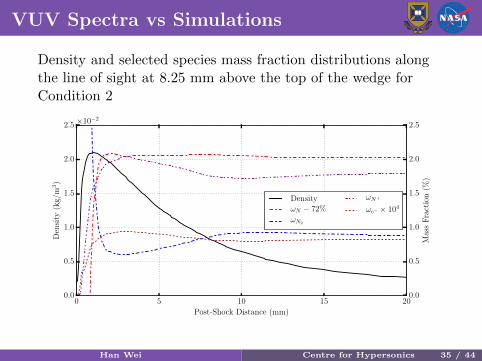
VUV Spectra vs Simulations
Density and selected species mass fraction distributions alongthe line of sight at 8.25 mm above the top of the wedge forCondition 2
0 5 10 15 20
Post-Shock Distance (mm)
0.0
0.5
1.0
1.5
2.0
2.5
Den
sity
(kg/
m3)
×10−2
0.0
0.5
1.0
1.5
2.0
2.5
Mas
sF
ract
ion
(%)
Density
ωN − 72%
ωN2
ωN+
ωe− × 104
Han Wei Centre for Hypersonics 35 / 44
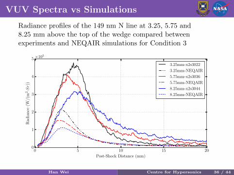
VUV Spectra vs Simulations
Radiance profiles of the 149 nm N line at 3.25, 5.75 and8.25 mm above the top of the wedge compared betweenexperiments and NEQAIR simulations for Condition 3
0 5 10 15 20
Post-Shock Distance (mm)
0
1
2
3
4
5
Rad
ian
ce(W
/(m
2·Sr)
)
×105
3.25mm-x2s3022
3.25mm-NEQAIR
5.75mm-x2s3036
5.75mm-NEQAIR
8.25mm-x2s3044
8.25mm-NEQAIR
Han Wei Centre for Hypersonics 36 / 44
VUV Spectra vs Simulations
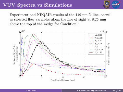
Experiment and NEQAIR results of the 149 nm N line, as wellas selected flow variables along the line of sight at 8.25 mmabove the top of the wedge for Condition 3
0 5 10 15 20
Post-Shock Distance (mm)
0
1
2
3
4
Rad
ian
ce(W
/(m
2·Sr)
)T
emp
erat
ure
(K)
×105
0
1
2
3
Nu
mb
erD
ensi
ty(c
m−
3)
×1017
x2s3044
NEQAIRTtr×10
Tve×10
NN
NN+×10
Ne+×10
Han Wei Centre for Hypersonics 37 / 44
VUV Spectra vs Simulations
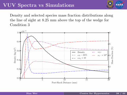
Density and selected species mass fraction distributions alongthe line of sight at 8.25 mm above the top of the wedge forCondition 3
0 5 10 15 20
Post-Shock Distance (mm)
0.0
0.2
0.4
0.6
0.8
1.0
Den
sity
(kg/
m3)
×10−2
0
2
4
6
8
Mas
sF
ract
ion
(%)
Density
ωN − 65%
ωN2 × 10
ωN+
ωe− × 104
Han Wei Centre for Hypersonics 38 / 44
Filtered Images vs Simulations
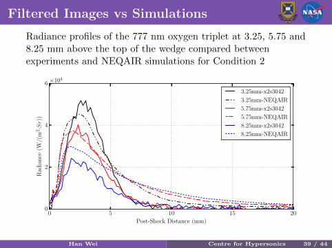
Radiance profiles of the 777 nm oxygen triplet at 3.25, 5.75 and8.25 mm above the top of the wedge compared betweenexperiments and NEQAIR simulations for Condition 2
0 5 10 15 20
Post-Shock Distance (mm)
0
2
4
6
Rad
ian
ce(W
/(m
2·Sr)
)
×104
3.25mm-x2s3042
3.25mm-NEQAIR
5.75mm-x2s3042
5.75mm-NEQAIR
8.25mm-x2s3042
8.25mm-NEQAIR
Han Wei Centre for Hypersonics 39 / 44
Filtered Images vs Simulations
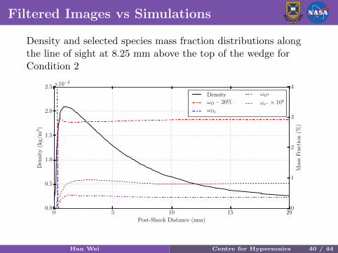
Density and selected species mass fraction distributions alongthe line of sight at 8.25 mm above the top of the wedge forCondition 2
0 5 10 15 20
Post-Shock Distance (mm)
0.0
0.5
1.0
1.5
2.0
2.5
Den
sity
(kg/
m3)
×10−2
0
1
2
3
4
Mas
sF
ract
ion
(%)
Density
ωO − 20%
ωO2
ωO+
ωe− × 104
Han Wei Centre for Hypersonics 40 / 44

Filtered Images vs Simulations
Radiance profiles of the 777 nm oxygen triplet at 3.25, 5.75 and8.25 mm above the top of the wedge compared betweenexperiments and NEQAIR simulations for Condition 3
0 5 10 15 20
Post-Shock Distance (mm)
0.0
0.5
1.0
1.5
Rad
ian
ce(W
/(m
2·Sr)
)
×105
3.25mm-x2s3044
3.25mm-NEQAIR
5.75mm-x2s3044
5.75mm-NEQAIR
8.25mm-x2s3044
8.25mm-NEQAIR
Han Wei Centre for Hypersonics 41 / 44
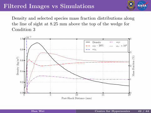
Filtered Images vs Simulations
Density and selected species mass fraction distributions alongthe line of sight at 8.25 mm above the top of the wedge forCondition 3
0 5 10 15 20
Post-Shock Distance (mm)
0.0
0.2
0.4
0.6
0.8
1.0
Den
sity
(kg/
m3)
×10−2
0
1
2
3
4
Mas
sF
ract
ion
(%)
Density
ωO − 20%
ωO2
ωO+
ωe− × 104
Han Wei Centre for Hypersonics 42 / 44
Outline
1 Introduction
2 Experimental Campaign
3 Numerical Simulation
4 Results and AnalysisFlow EstablishmentVUV Spectra
5 Conclusions
Han Wei Centre for Hypersonics 42 / 44
Conclusions
The spatial profiles of 149 and 174nm N radiance are ingeneral of larger spans than those predicted by NEQAIR
For Conditions 2 and 3, the peak radiance levels aresignificantly underestimated. Large departures of predictedradiance values from experiment appear to occur at thestart of the expansion fan where the electron-ionrecombination process commences
NEQAIR results agree well with the filtered images of777nm oxygen triplet in the compression region and at thestart of the expansion fan for Condition 2. For Condition3, radiance in the compression region and at the start ofthe expansion fan are underpredicted by as much as 40%,but the afterbody radiance is overpredicted by up to 100%
Han Wei Centre for Hypersonics 43 / 44
Many Thanks
Han Wei Centre for Hypersonics 44 / 44
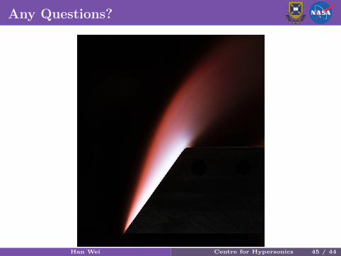
Any Questions?
Figure: Long exposure image of CO2 flow over the wedge
Han Wei Centre for Hypersonics 45 / 44
Recommended