Tishk International UniversityEngineering FacultyPetroleum and Mining Engineering Department
Engineering Drawing
First Grade- Fall Semester 2020-2021
Lecture 6: Orthographic Projections
Instructor: Sheida Mostafa Sheikheh
Content:
■ Plane Geometry and Solid Geometry
■ Projection
■ Types of Projections:
1. Pictorial Projections
2. Orthographic Projections
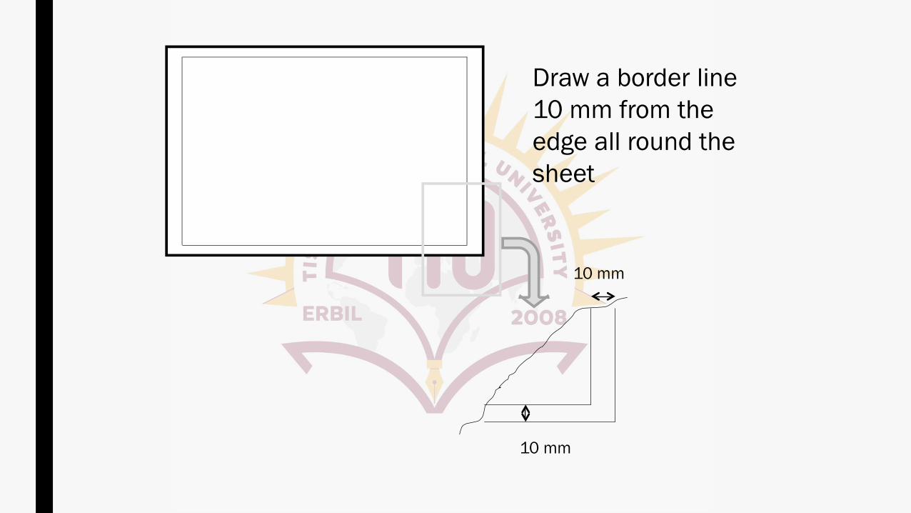
10 mm
10 mm
Draw a border line
10 mm from the
edge all round the
sheet
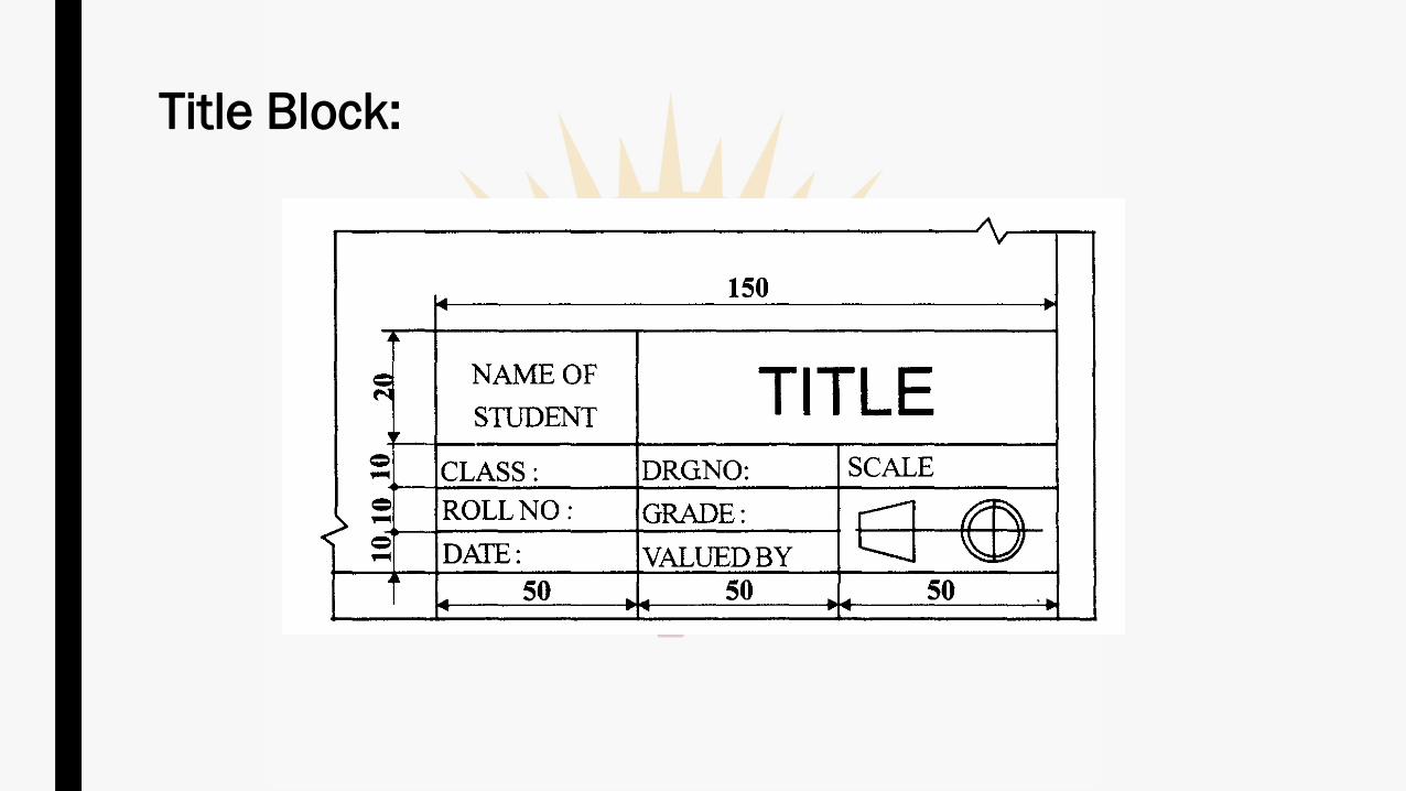
Title Block:
✓ The study of geometry can be broken into two broad types:
➢ Plane geometry, which deals with only two dimensions, and
➢ solid geometry which allows all three.
✓ The world around us is obviously three-dimensional, having width,
depth and height.
✓ Solid geometry deals with objects in that space such as cubes and
spheres.
✓ Plane geometry deals in objects that are flat, such as triangles and
lines, that can be drawn on a flat piece of paper.
Plane Geometry and Solid Geometry:
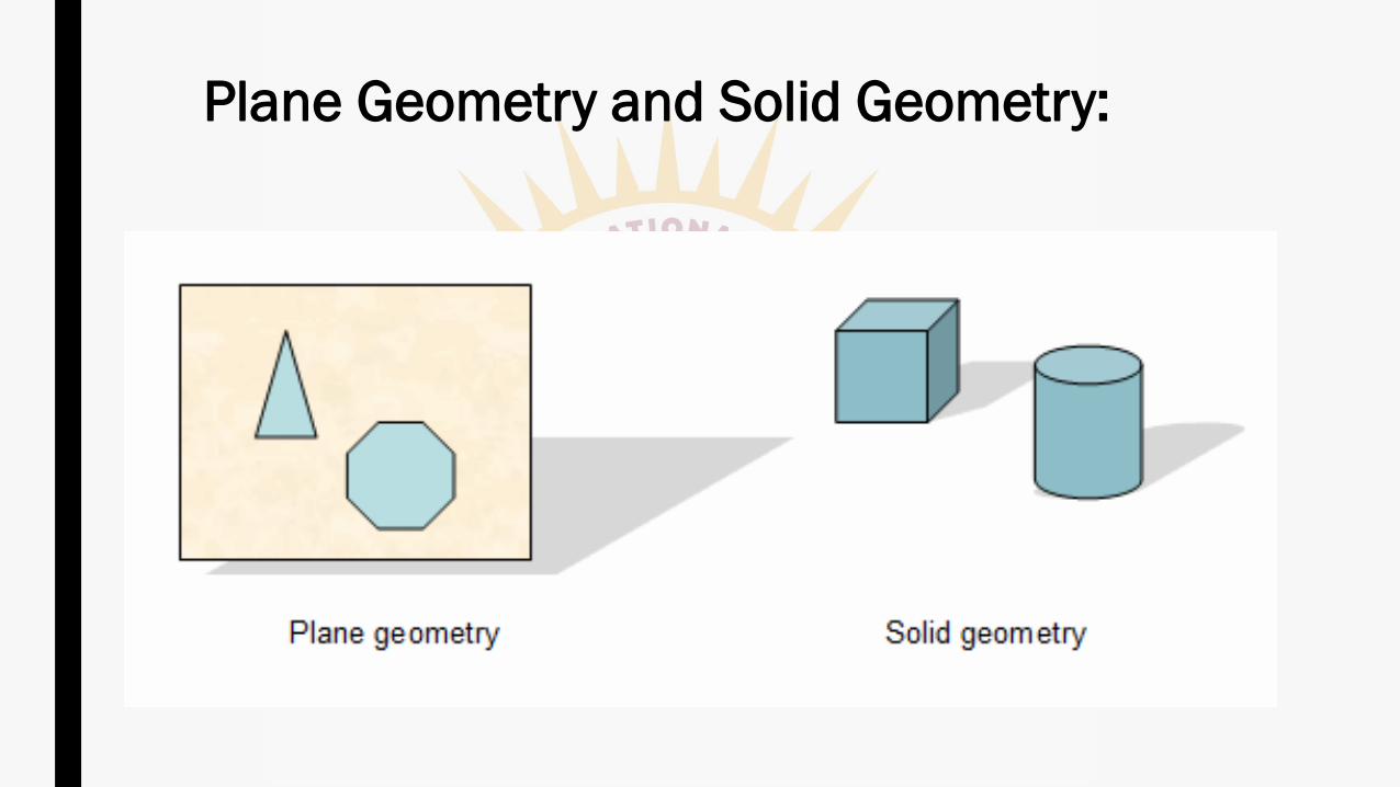
Plane Geometry and Solid Geometry:
✓ Engineering drawing, particularly solid geometry is the graphic
language used in the industry to:
➢ Record the ideas and information necessary in the form of blueprints
to make machines, buildings, structures etc., by engineers and
technicians who design, develop, manufacture and market the
products.
Solid Geometry:
✓ As per the optical physics, an object is seen when the light rays called
visual rays coming from the object strike the observer's eye. The size
of the image formed in the retina (the area at the back of the eye that
receives light and sends pictures of what the eye sees to the brain)
depends on the distance of the observer from the object.
Projection:
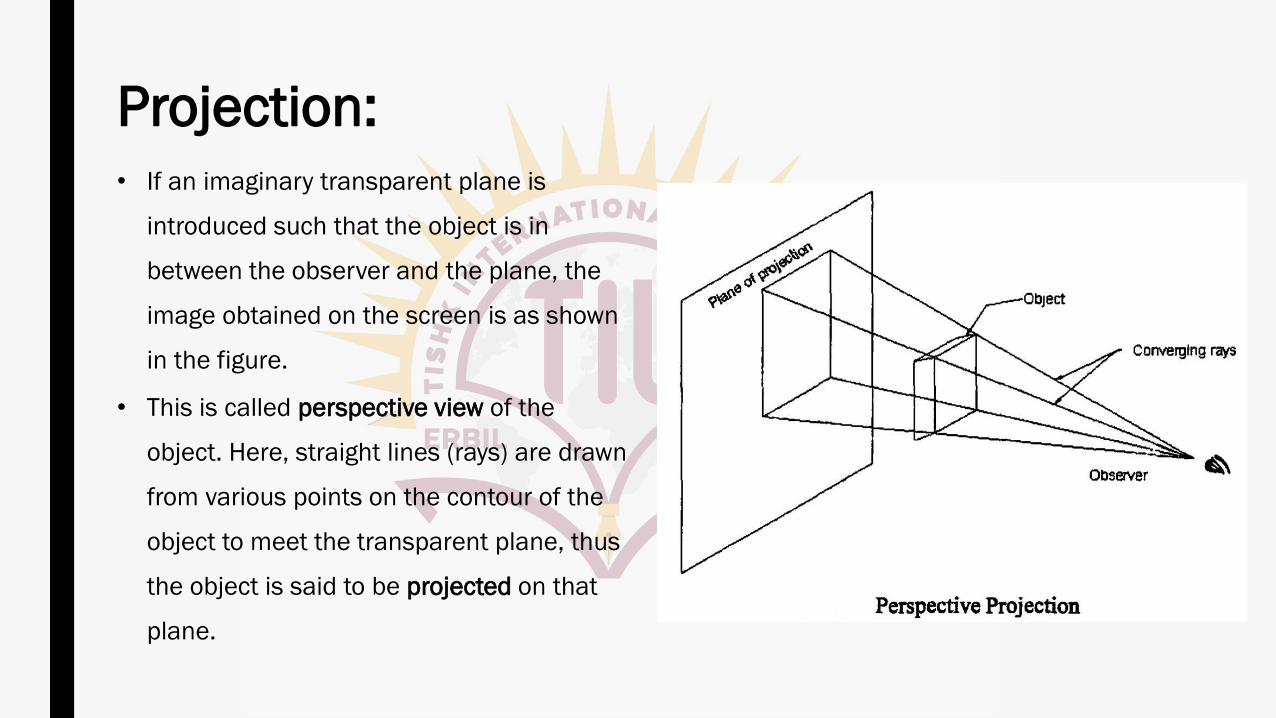
Projection: • If an imaginary transparent plane is
introduced such that the object is in
between the observer and the plane, the
image obtained on the screen is as shown
in the figure.
• This is called perspective view of the
object. Here, straight lines (rays) are drawn
from various points on the contour of the
object to meet the transparent plane, thus
the object is said to be projected on that
plane.
Projection:
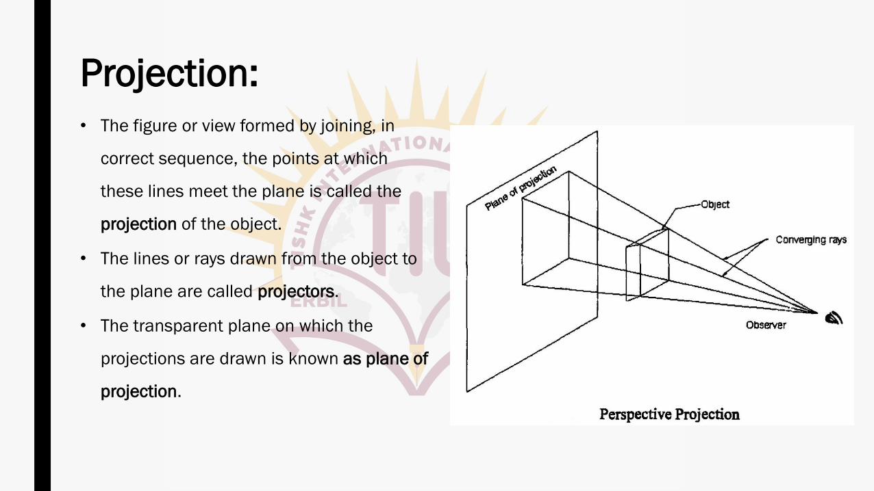
• The figure or view formed by joining, in
correct sequence, the points at which
these lines meet the plane is called the
projection of the object.
• The lines or rays drawn from the object to
the plane are called projectors.
• The transparent plane on which the
projections are drawn is known as plane of
projection.
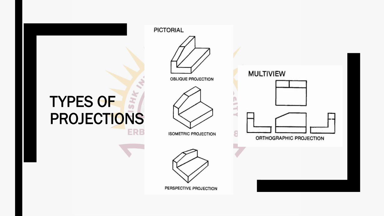
1. Pictorial Projections:
(i) Perspective Projection
(ii) Isometric Projection
(iii) Oblique Projection
2. Orthographic Projections
Types of Projections:
1. Pictorial Projections:
✓ The Projections in which the description of the object is completely
understood in one view is known as pictorial projection.
✓ They have the advantage of conveying an immediate impression of the
general shape and details of the object, but not its true dimensions or
sizes.
Types of Projections:
2. Orthographic Projections:
✓ 'ORTHO' means right angle and orthographic means right angled
drawing. When the projectors are perpendicular to the plane on which
the projection is obtained, it is known as orthographic projection.
Types of Projections:
TYPES OF PROJECTIONS
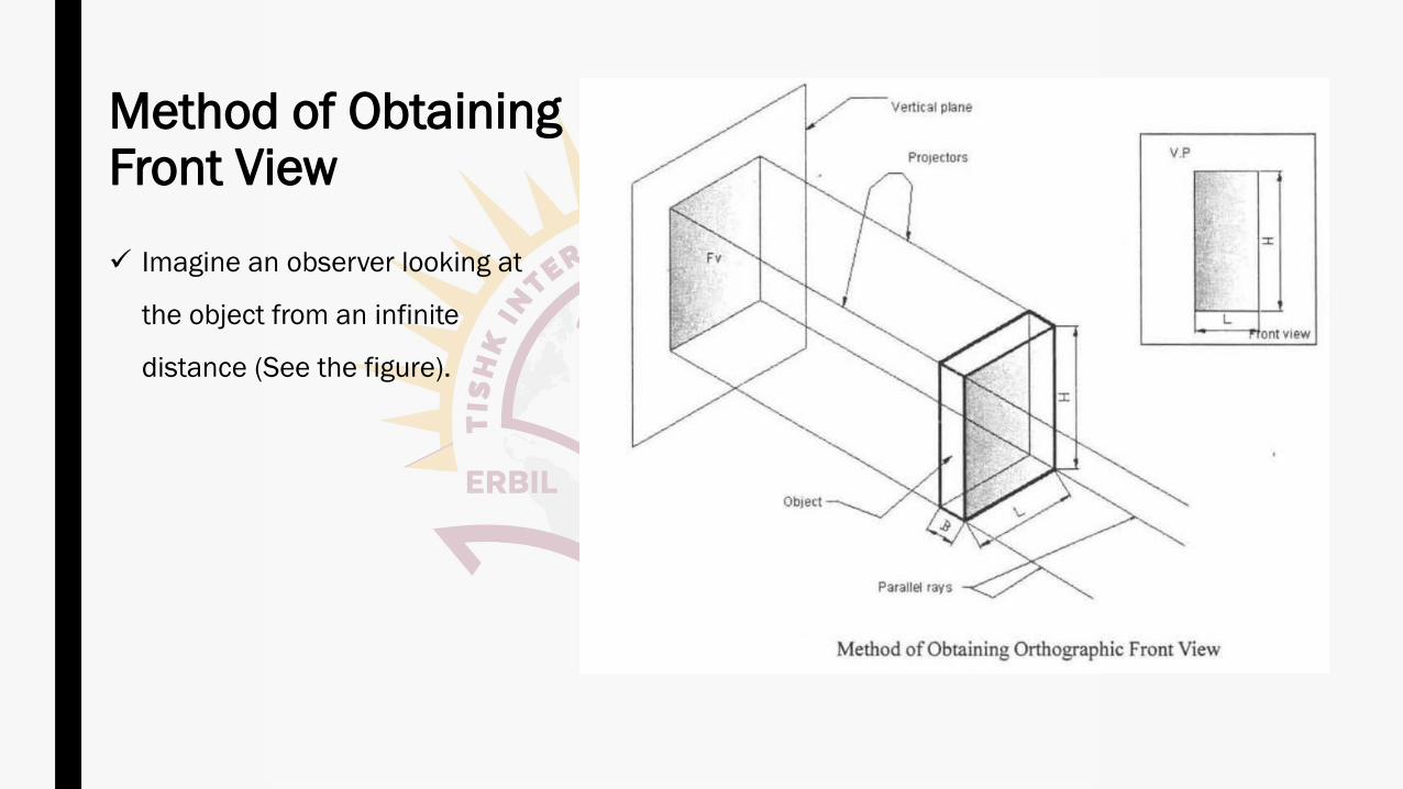
Method of Obtaining Front View
✓ Imagine an observer looking at
the object from an infinite
distance (See the figure).
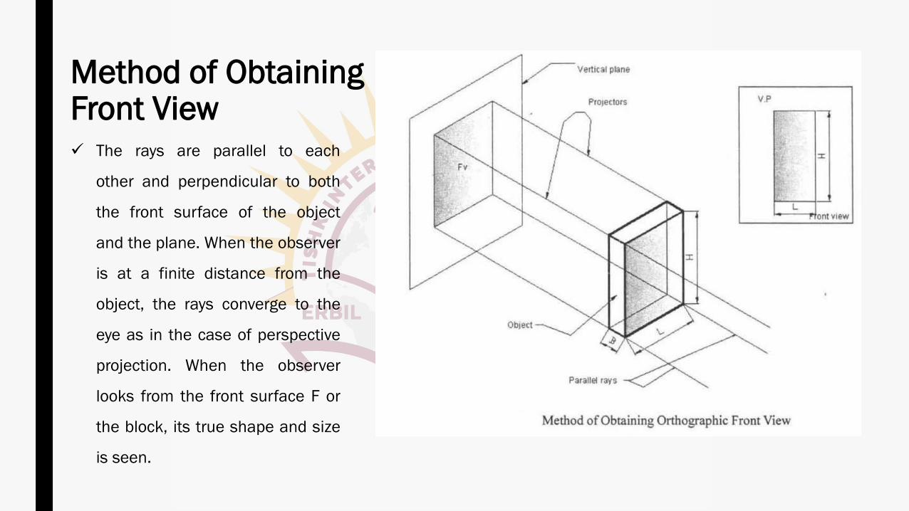
Method of Obtaining Front View✓ The rays are parallel to each
other and perpendicular to both
the front surface of the object
and the plane. When the observer
is at a finite distance from the
object, the rays converge to the
eye as in the case of perspective
projection. When the observer
looks from the front surface F or
the block, its true shape and size
is seen.
Method of Obtaining Front View
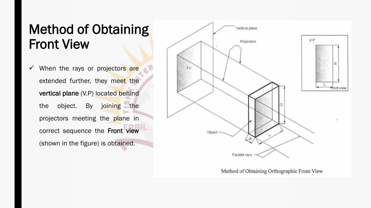
✓ When the rays or projectors are
extended further, they meet the
vertical plane (V.P) located behind
the object. By joining the
projectors meeting the plane in
correct sequence the Front view
(shown in the figure) is obtained.
✓ Front view shows only two dimensions of the object, Viz. length L and
height H.
✓ It does not show the breadth B.
✓ Thus, one view or projection is insufficient for the complete description
of the object.
Method of Obtaining Front View
Method of Obtaining Top View:
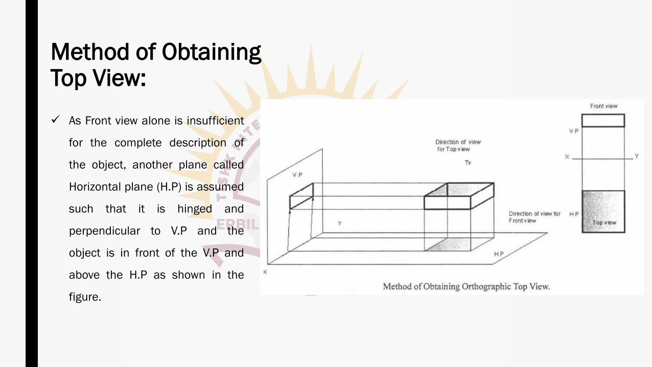
✓ As Front view alone is insufficient
for the complete description of
the object, another plane called
Horizontal plane (H.P) is assumed
such that it is hinged and
perpendicular to V.P and the
object is in front of the V.P and
above the H.P as shown in the
figure.
Method of Obtaining Top View:
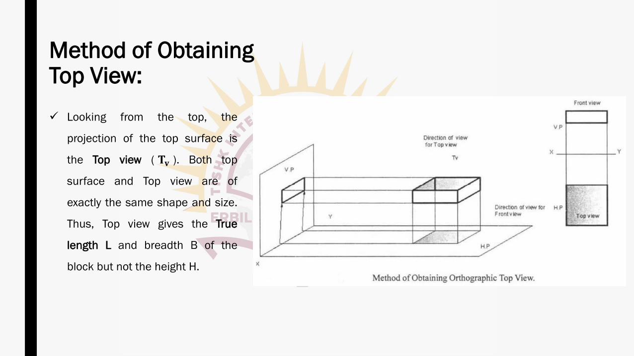
✓ Looking from the top, the
projection of the top surface is
the Top view ( 𝐓𝐯 ). Both top
surface and Top view are of
exactly the same shape and size.
Thus, Top view gives the True
length L and breadth B of the
block but not the height H.
(1) Each projection shows that surface of the object which is nearer to
the observer. and far away from the plane.
(2) Orthographic projection is the standard drawing form of the industrial
world.
(3) XY Line: The line of intersection of VP and H.P is called the reference
line and is denoted as xy.
Notes
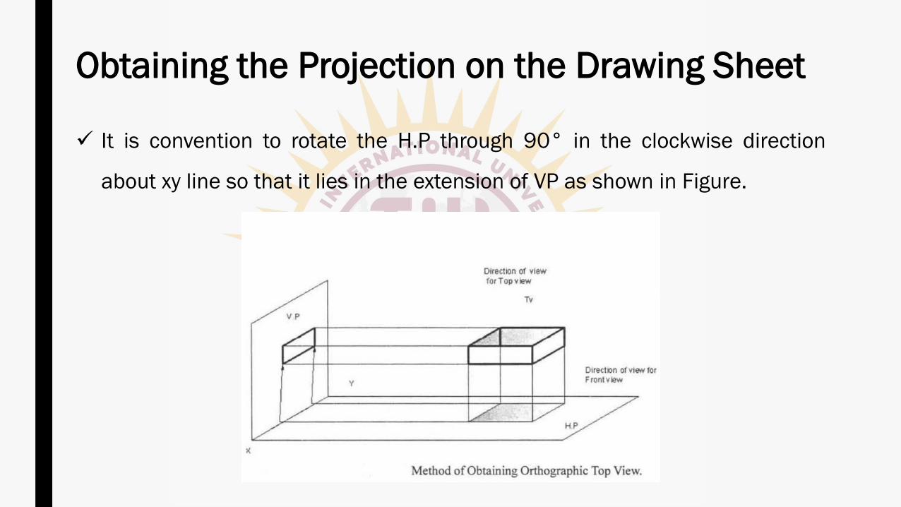
✓ It is convention to rotate the H.P through 90° in the clockwise direction
about xy line so that it lies in the extension of VP as shown in Figure.
Obtaining the Projection on the Drawing Sheet
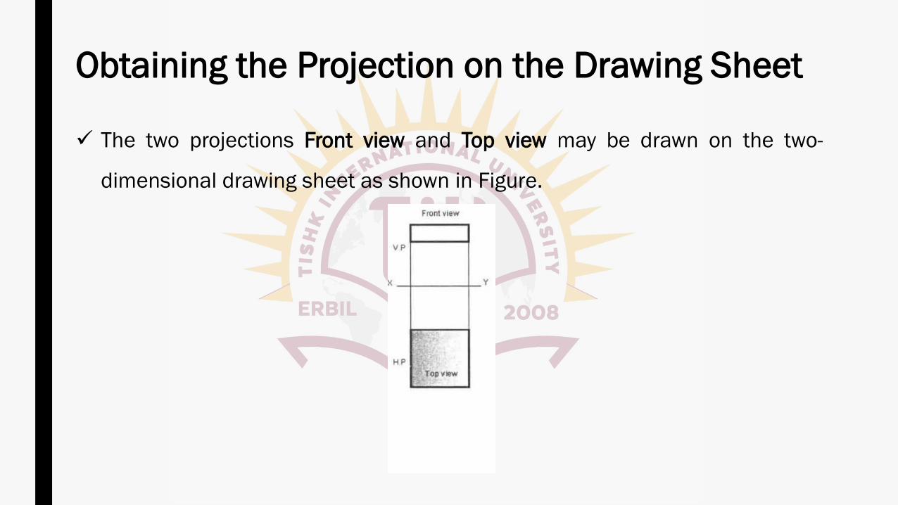
✓ The two projections Front view and Top view may be drawn on the two-
dimensional drawing sheet as shown in Figure.
Obtaining the Projection on the Drawing Sheet
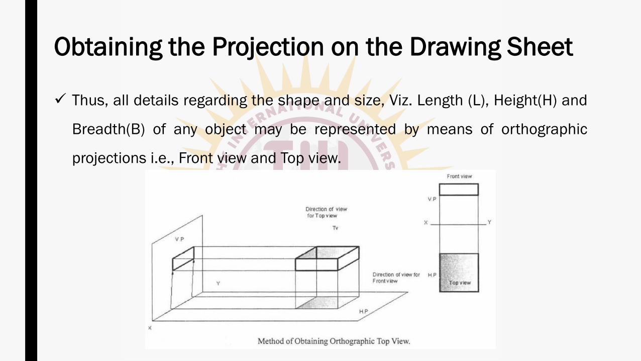
✓ Thus, all details regarding the shape and size, Viz. Length (L), Height(H) and
Breadth(B) of any object may be represented by means of orthographic
projections i.e., Front view and Top view.
Obtaining the Projection on the Drawing Sheet
✓ V.P and H.P are called as Principal planes of projection or reference planes.
✓ They are always transparent and at right angles to each other.
✓ The projection on V.P is designated as Front view and the projection on H.P
as Top view.
Terms Used
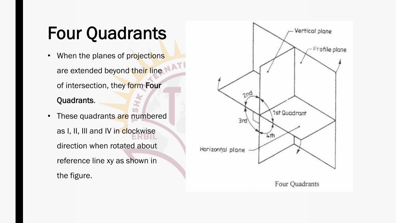
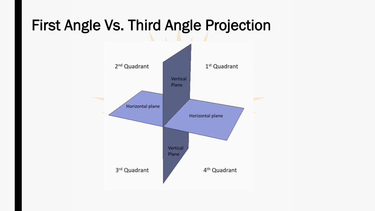
Four Quadrants• When the planes of projections
are extended beyond their line
of intersection, they form Four
Quadrants.
• These quadrants are numbered
as I, II, Ill and IV in clockwise
direction when rotated about
reference line xy as shown in
the figure.
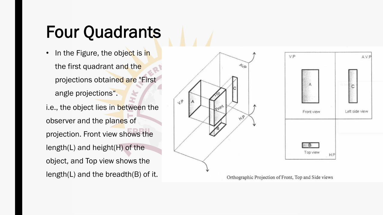
Four Quadrants• In the Figure, the object is in
the first quadrant and the
projections obtained are "First
angle projections“.
i.e., the object lies in between the
observer and the planes of
projection. Front view shows the
length(L) and height(H) of the
object, and Top view shows the
length(L) and the breadth(B) of it.

Four Quadrants• The object may be situated in
anyone of four quadrants, its
position relative to the planes
being described as in front of V.P
and above H.P in the first
quadrant and so on.
• Figure shows the two principle
planes H.P and V.P and another
Auxiliary Vertical Plane (AVP).
• AVP is perpendicular to both VP
and H.P.
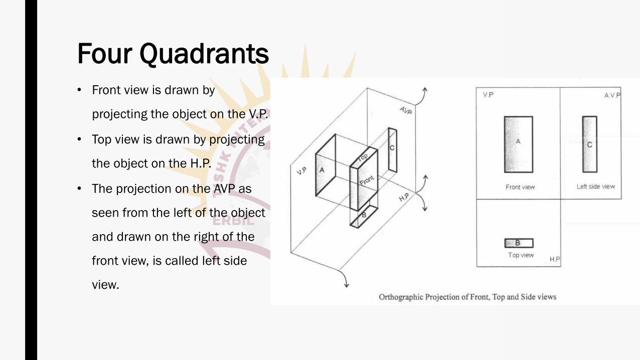
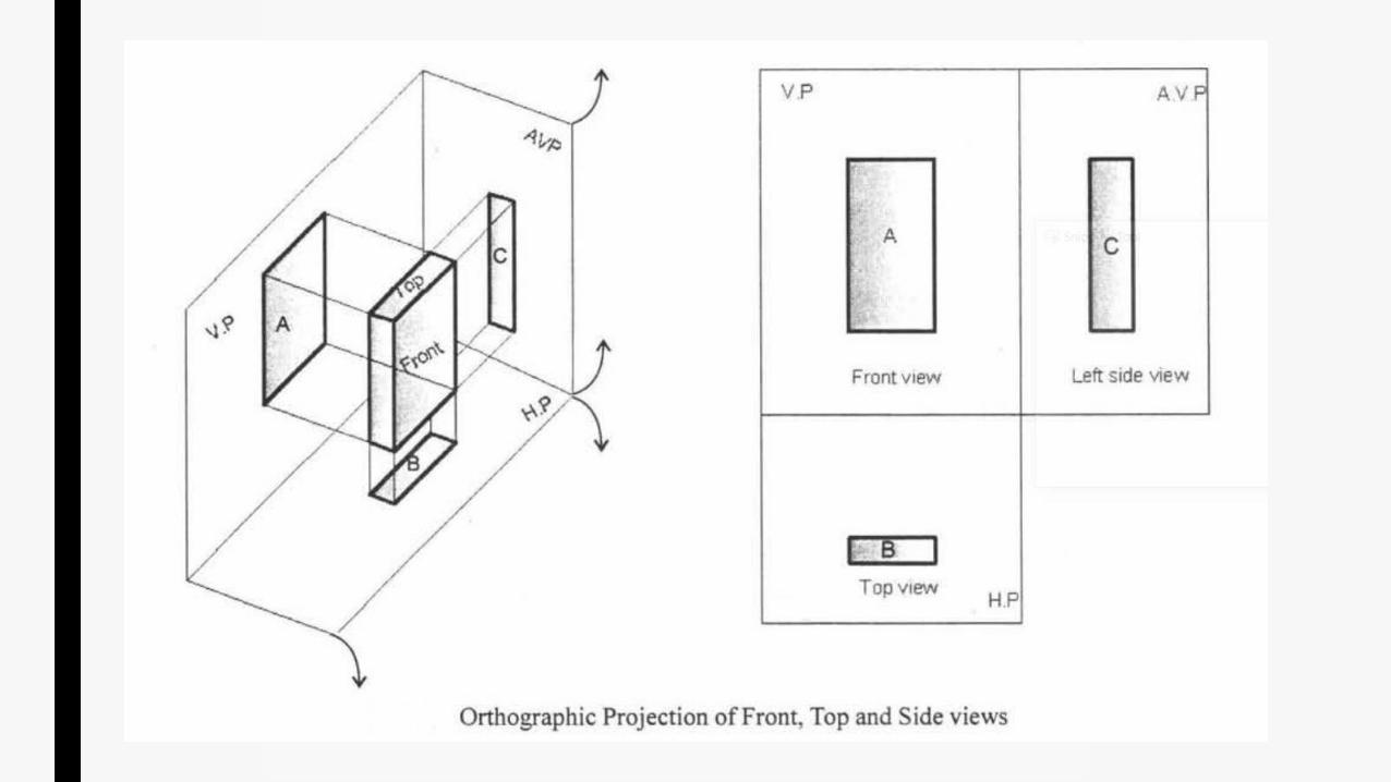
Four Quadrants• Front view is drawn by
projecting the object on the V.P.
• Top view is drawn by projecting
the object on the H.P.
• The projection on the AVP as
seen from the left of the object
and drawn on the right of the
front view, is called left side
view.
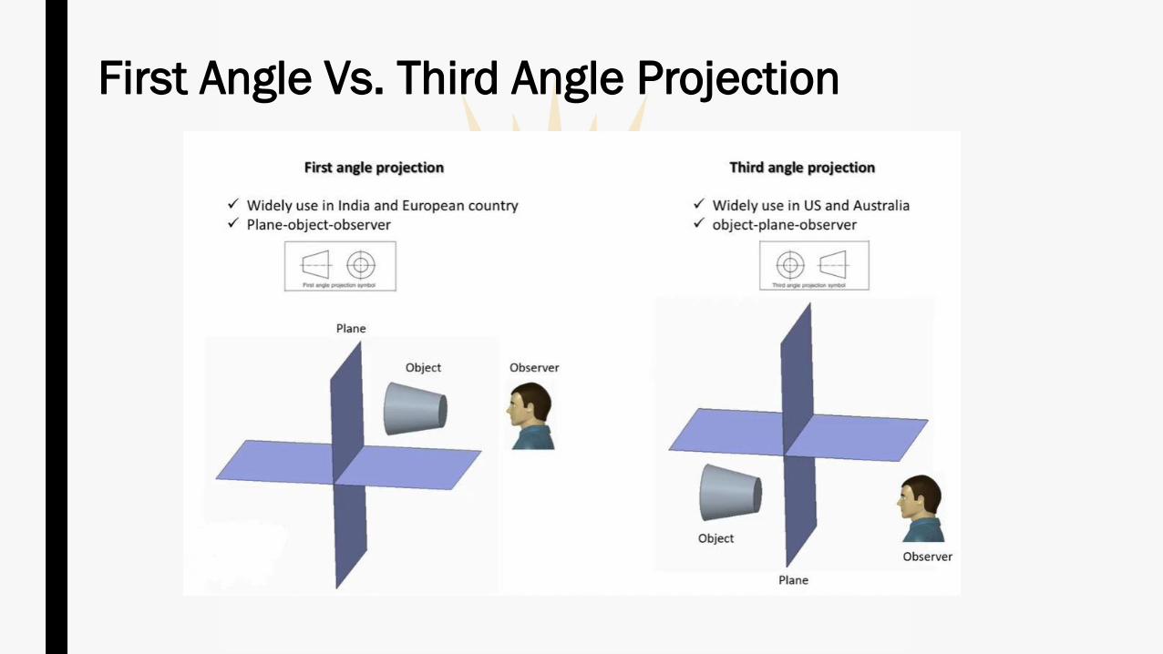
✓ When the object is situated in First Quadrant, that is, in front of V.P and above H.P, the
projections obtained on these planes is called First angle projection.
(i) The object lies in between the observer and the plane of projection.
(ii) The front view is drawn above the xy line and the top view below xy. (above xy line is V.P
and below xy line is H.P).
(iii) In the front view, H.P coincides with xy line and in top view V.P coincides with xy line.
(iv) Front view shows the length(L) and height(H) of the object and Top view shows the
length(L) and breadth(B) or width(W) or thickness(T) of it.
First Angle Projection
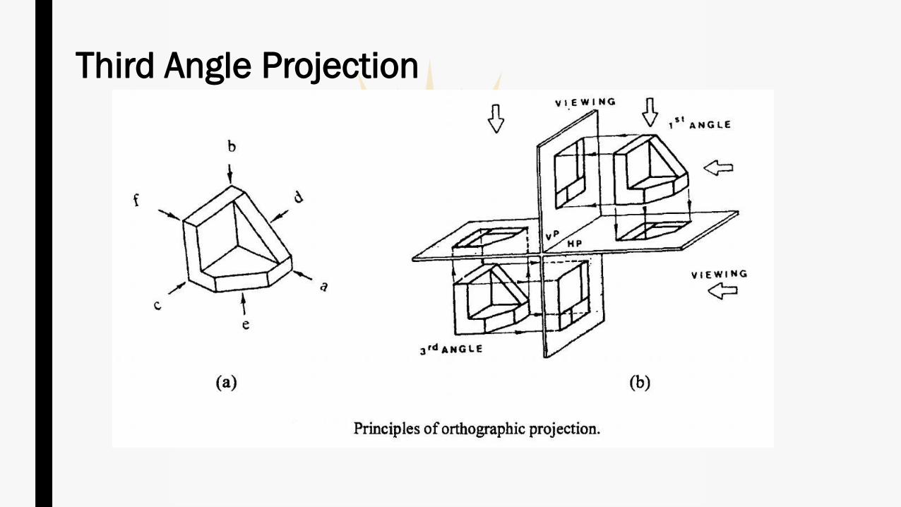
✓ In this, the object is situated in Third Quadrant.
✓ The Planes of projection lie between the object and the observer.
✓ The front view comes below the xy line and the top view about it.
Third Angle Projection
Third Angle Projection
Designation and Relative Position of Views
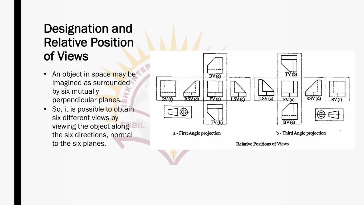
• An object in space may be
imagined as surrounded
by six mutually
perpendicular planes.
• So, it is possible to obtain
six different views by
viewing the object along
the six directions, normal
to the six planes.
Designation and Relative Position of Views
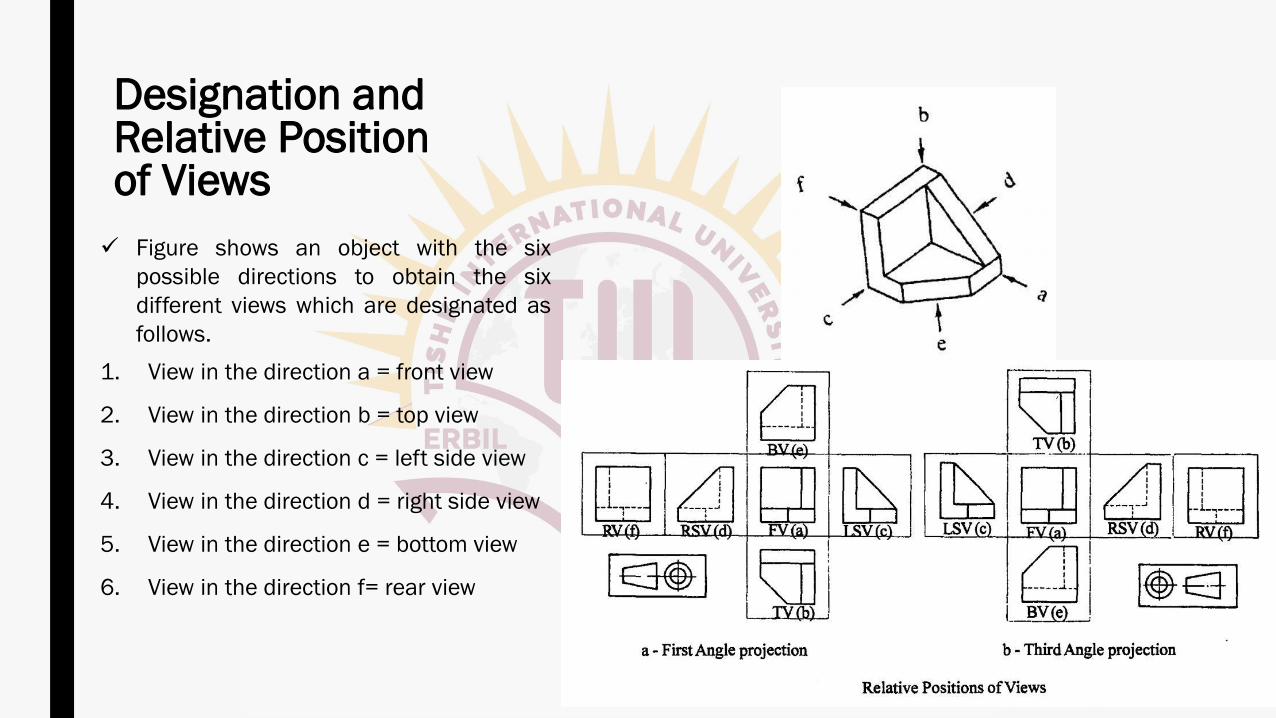
✓ Figure shows an object with the six
possible directions to obtain the six
different views which are designated as
follows.
1. View in the direction a = front view
2. View in the direction b = top view
3. View in the direction c = left side view
4. View in the direction d = right side view
5. View in the direction e = bottom view
6. View in the direction f= rear view
Designation and Relative Position of Views
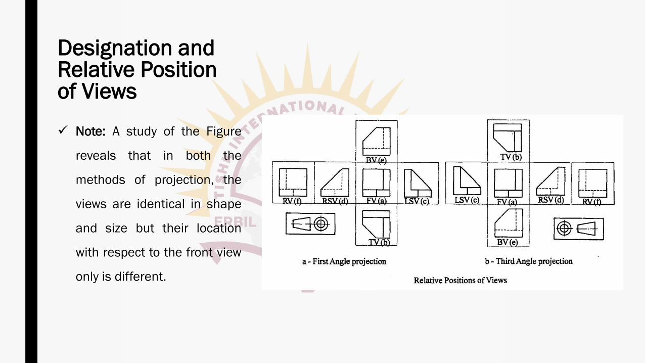
✓ Note: A study of the Figure
reveals that in both the
methods of projection, the
views are identical in shape
and size but their location
with respect to the front view
only is different.

First Angle Vs. Third Angle Projection
First Angle Vs. Third Angle Projection
First Angle Vs. Third Angle Projection
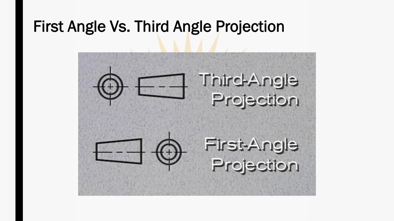
First Angle Vs. Third Angle Projection
Recommended