Embed Size (px)
Citation preview
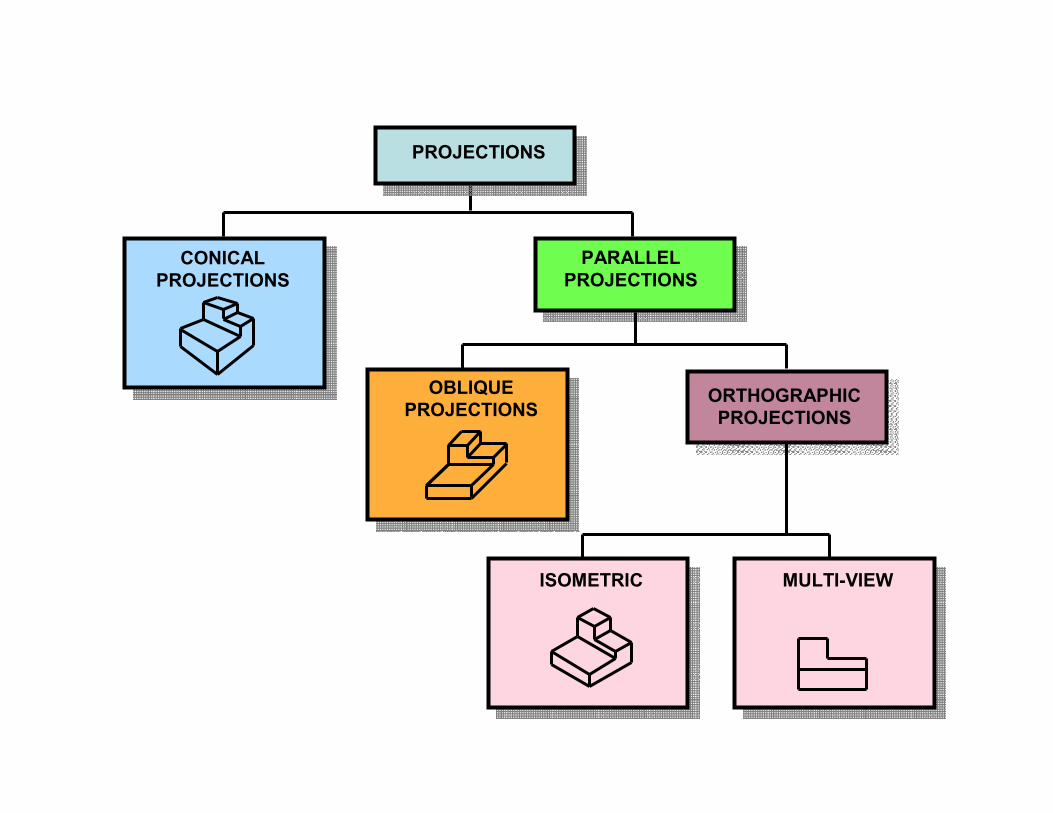
PROJECTIONS
PARALLEL
PROJECTIONS
ORTHOGRAPHIC
PROJECTIONS
CONICAL
PROJECTIONS
OBLIQUE
PROJECTIONS
ISOMETRIC MULTI-VIEW
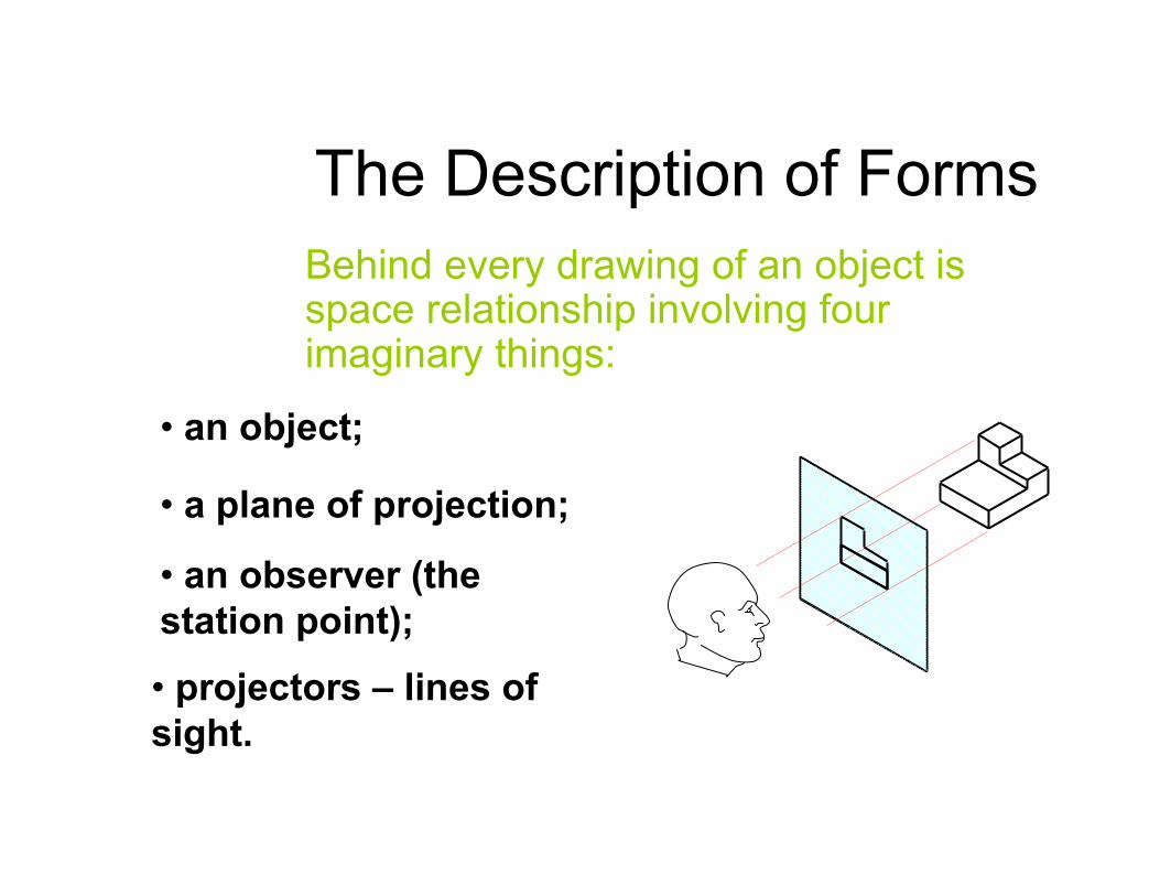
The Description of Forms
Behind every drawing of an object is space relationship involving four imaginary things:
• an object;
• a plane of projection;
• an observer (the
station point);
• projectors – lines of
sight.
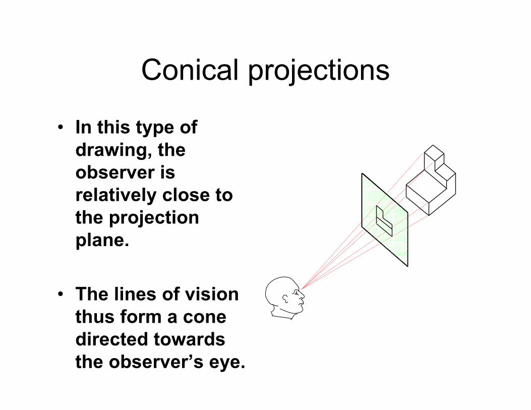
Conical projections
• In this type of
drawing, the
observer is
relatively close to
the projection
plane.
• The lines of vision
thus form a cone
directed towards
the observer’s eye.
• In conical projections, the edges
which are closer to an observer,
are larger compared to the edges
which are farther
• When drawing conical projections,
use at least 2 vanishing points
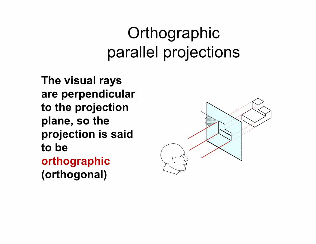
Orthographic
parallel projections
The visual rays
are perpendicular
to the projection
plane, so the
projection is said
to be
orthographic
(orthogonal)
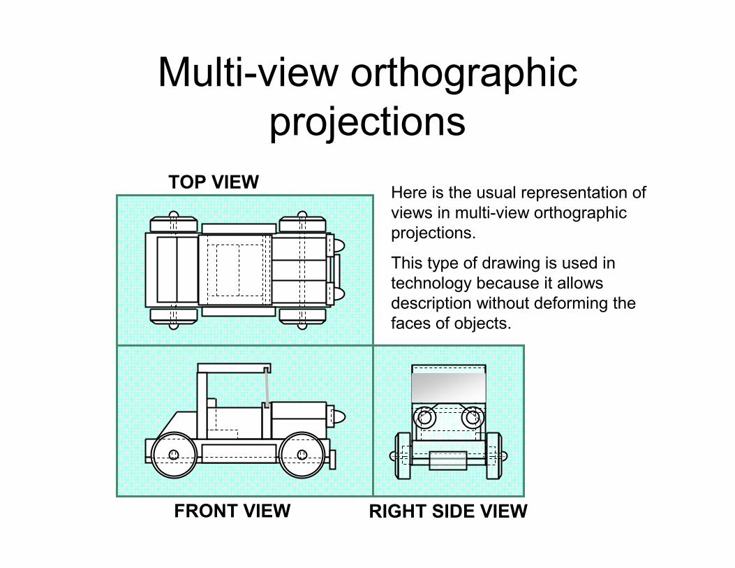
Multi-view orthographic
projections
TOP VIEW
FRONT VIEW RIGHT SIDE VIEW
Here is the usual representation of
views in multi-view orthographic
projections.
This type of drawing is used in
technology because it allows
description without deforming the
faces of objects.
• Top view
• Front view, and
• Right Side view
are three commonly used views in
multiview projection
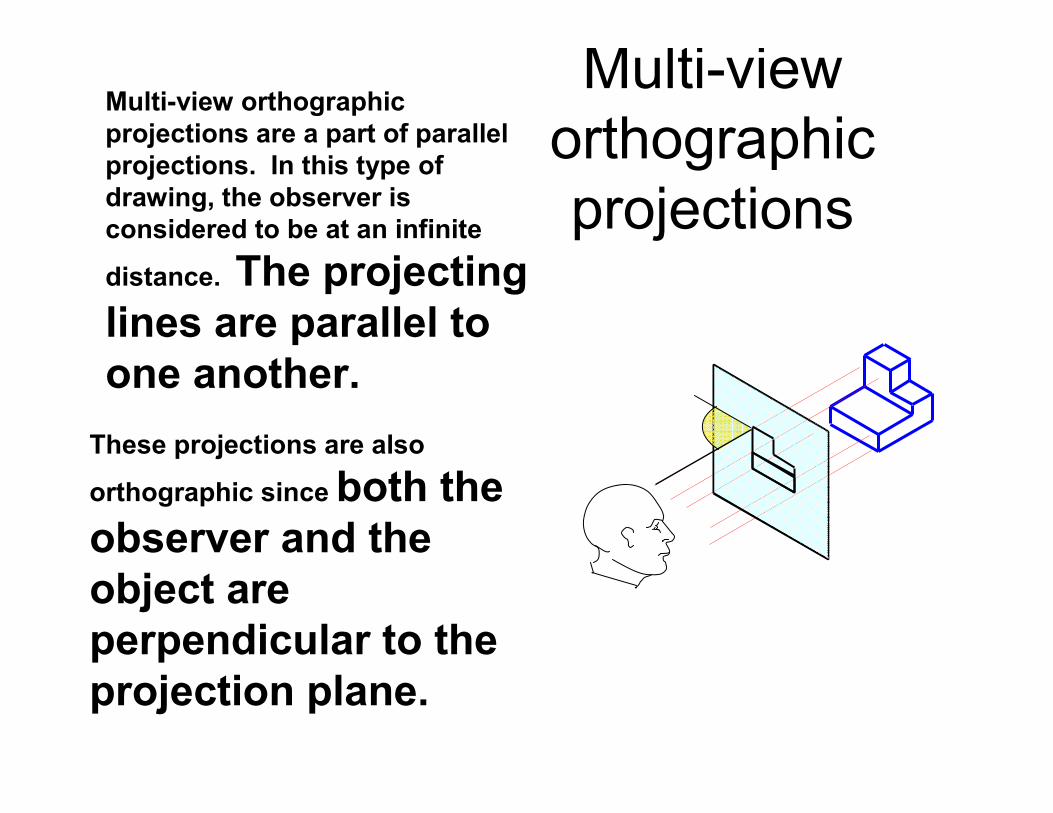
Multi-view
orthographic
projections
Multi-view orthographic
projections are a part of parallel
projections. In this type of
drawing, the observer is
considered to be at an infinite
distance. The projecting
lines are parallel to
one another.
These projections are also
orthographic since both the
observer and the
object are
perpendicular to the
projection plane.
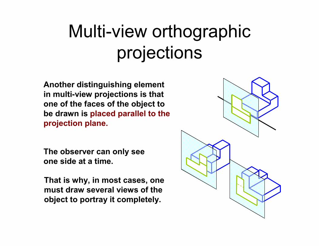
Multi-view orthographic
projections
Another distinguishing element
in multi-view projections is that
one of the faces of the object to
be drawn is placed parallel to the
projection plane.
That is why, in most cases, one
must draw several views of the
object to portray it completely.
The observer can only see
one side at a time.
Multi-view orthographic
projections
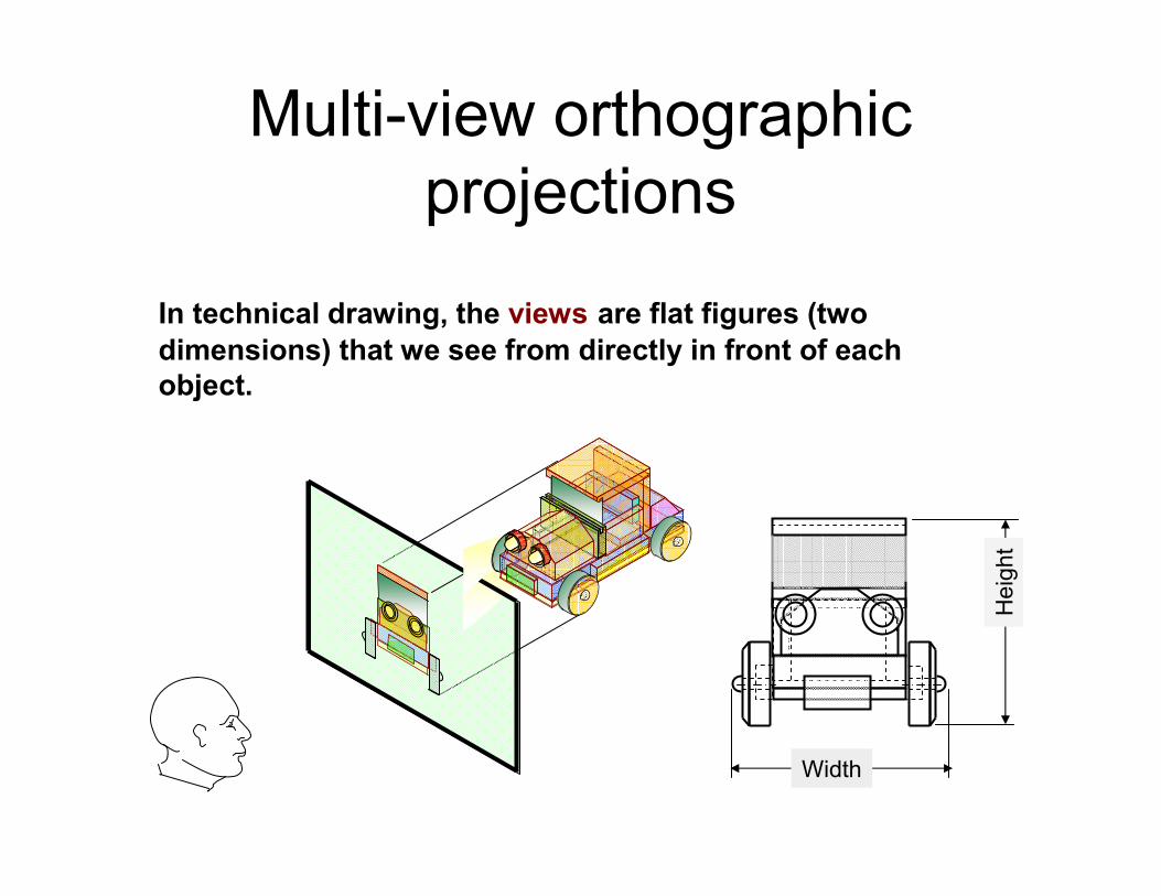
In technical drawing, the views are flat figures (two
dimensions) that we see from directly in front of each
object.
Width
Heig
ht
Multi-view orthographic
projections
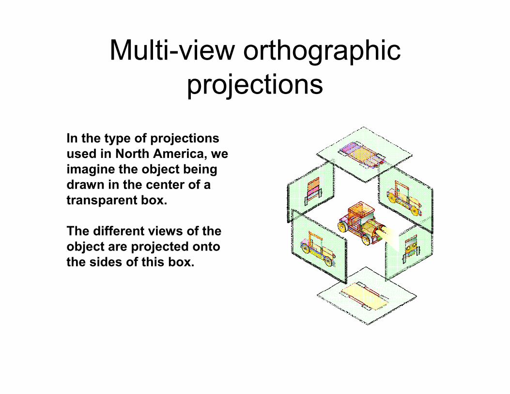
In the type of projections
used in North America, we
imagine the object being
drawn in the center of a
transparent box.
The different views of the
object are projected onto
the sides of this box.
Multi-view orthographic
projections
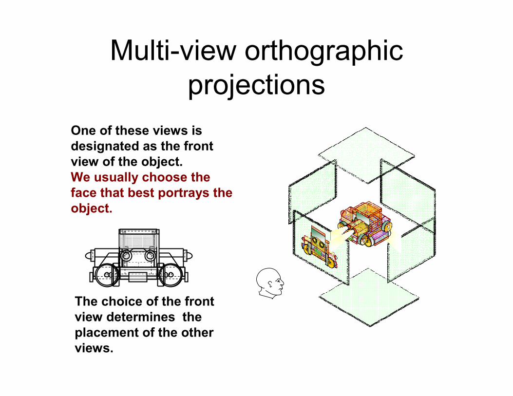
One of these views is
designated as the front
view of the object.
We usually choose the
face that best portrays the
object.
The choice of the front
view determines the
placement of the other
views.
ISOMETRIC Drawings
• In Isometric projection :
1) all three dimensions can be
seen in one view
2) the intersecting edges of the
object are on the axes that are
spread at 120. This way the
angles between all intersecting
edges are either 120°or 60°.
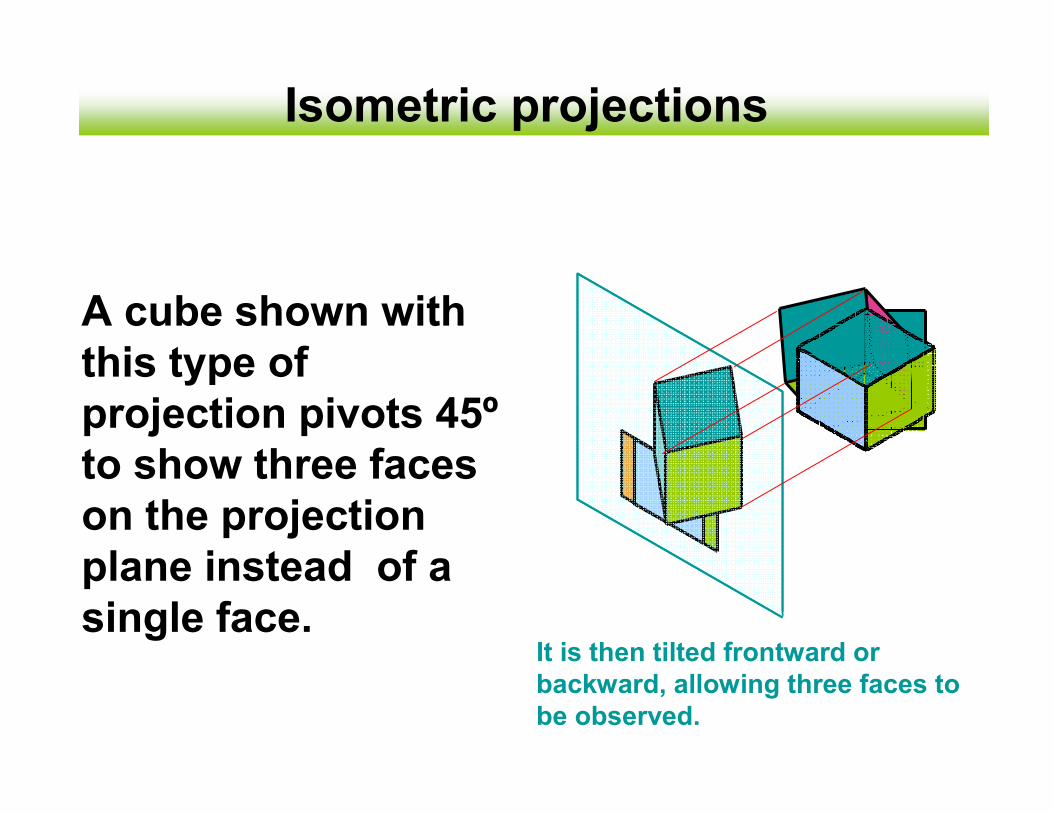
Isometric projections
A cube shown with
this type of
projection pivots 45º
to show three faces
on the projection
plane instead of a
single face.It is then tilted frontward or
backward, allowing three faces to
be observed.
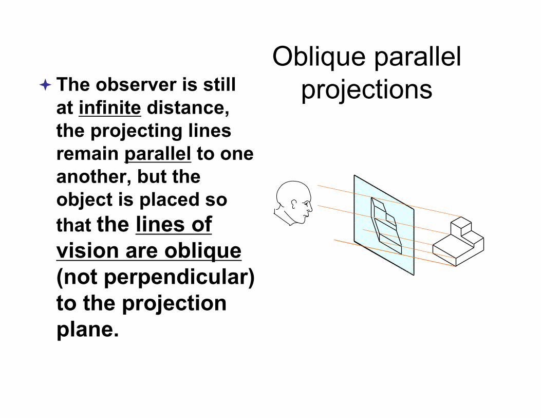
Oblique parallel
projections�The observer is still
at infinite distance,
the projecting lines
remain parallel to one
another, but the
object is placed so
that the lines of
vision are oblique
(not perpendicular)
to the projection
plane.
• OBLIQUE projections are unnatural
projections, because the angles
and lengths of edges are wrong. It
is impossible to actually see objects
in this way
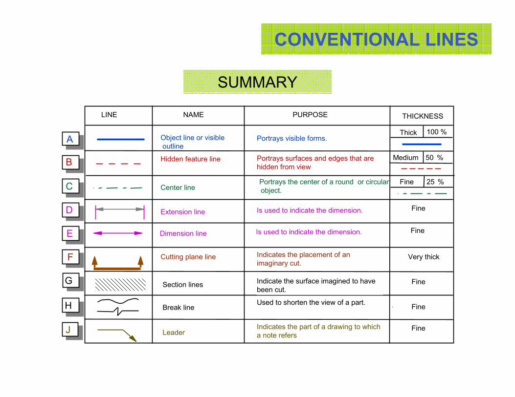
CONVENTIONAL LINES
SUMMARY
Portrays surfaces and edges that are
hidden from view
Indicates the placement of an
imaginary cut.
Hidden feature line
A
B
C
D
E
F
G
H
NAME PURPOSE THICKNESS
J
LINE
Object line or visible
outline
Cutting plane line
Break line
Leader
Portrays visible forms.
Indicate the surface imagined to have
been cut.
Used to shorten the view of a part.
Indicates the part of a drawing to which
a note refers
Is used to indicate the dimension.Dimension line Fine
Medium
Thick
Very thick
Center linePortrays the center of a round or circular
object.
Fine
Fine
Fine
Fine
Is used to indicate the dimension.Extension lineFine
Section lines
100 %
50 %
25 %
CONVENTIONAL LINES
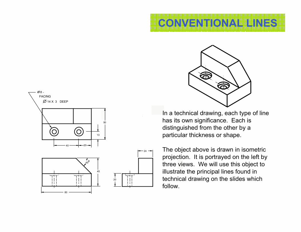
In a technical drawing, each type of line
has its own significance. Each is
distinguished from the other by a
particular thickness or shape.
The object above is drawn in isometric
projection. It is portrayed on the left by
three views. We will use this object to
illustrate the principal lines found in
technical drawing on the slides which
follow.
8 -
LAMAGE
14 X 3 PROF.
45°
13
20
50
40
20
24
45
80
FACING
DEEP
CONVENTIONAL LINES
A
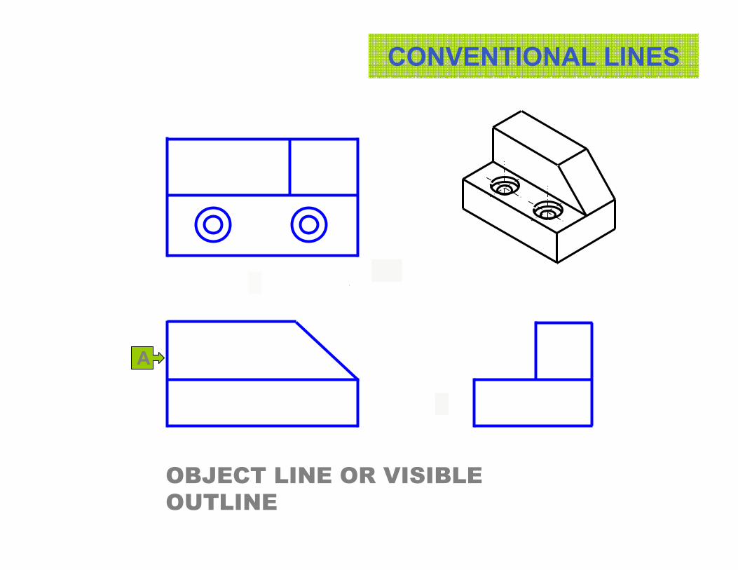
OBJECT LINE OR VISIBLE
OUTLINE
CONVENTIONAL LINES
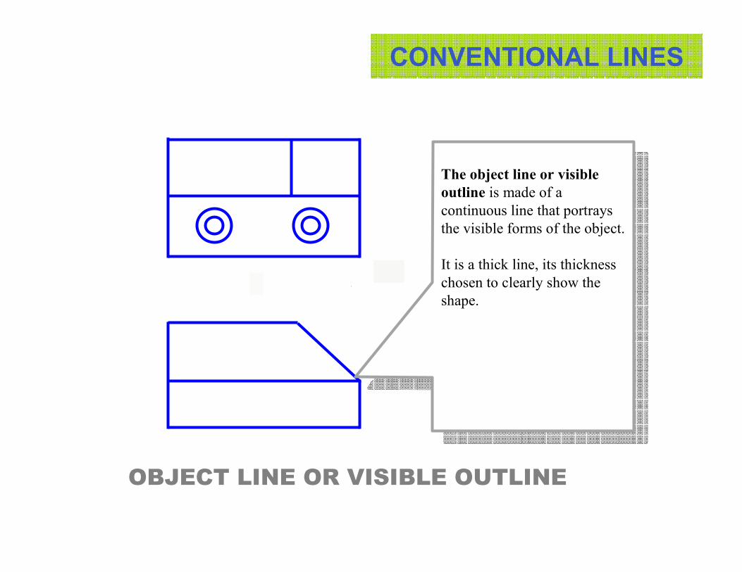
The object line or visible
outline is made of a
continuous line that portrays
the visible forms of the object.
It is a thick line, its thickness
chosen to clearly show the
shape.
OBJECT LINE OR VISIBLE OUTLINE
CONVENTIONAL LINES
BB
HIDDEN FEATURE LINE
CONVENTIONAL LINES
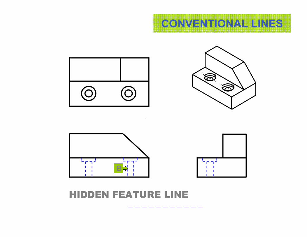
B
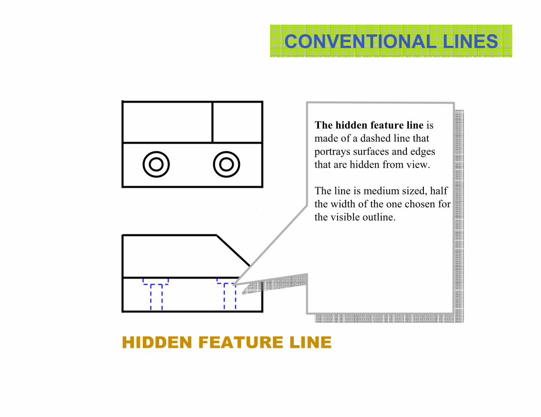
The hidden feature line is
made of a dashed line that
portrays surfaces and edges
that are hidden from view.
The line is medium sized, half
the width of the one chosen for
the visible outline.
HIDDEN FEATURE LINE
CONVENTIONAL LINES
C
C
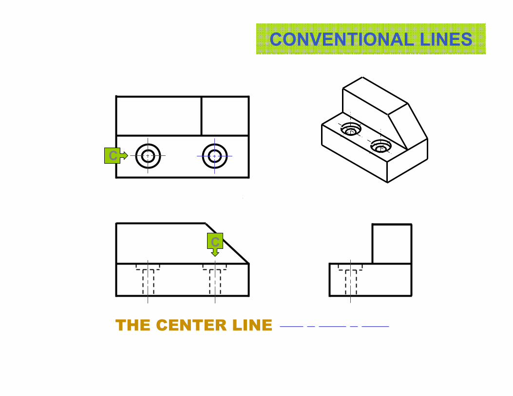
THE CENTER LINE
CONVENTIONAL LINES
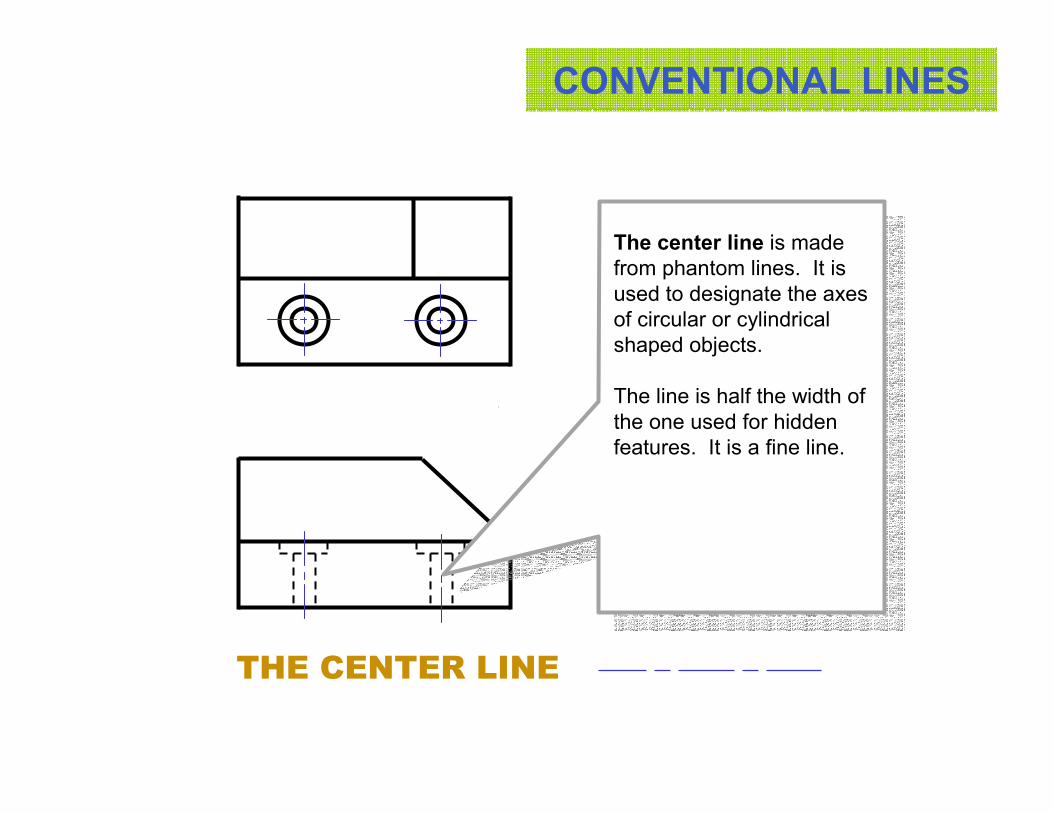
The center line is made
from phantom lines. It is
used to designate the axes
of circular or cylindrical
shaped objects.
The line is half the width of
the one used for hidden
features. It is a fine line.
THE CENTER LINE
CONVENTIONAL LINES
D
DIMENSION LINE
CONVENTIONAL LINES
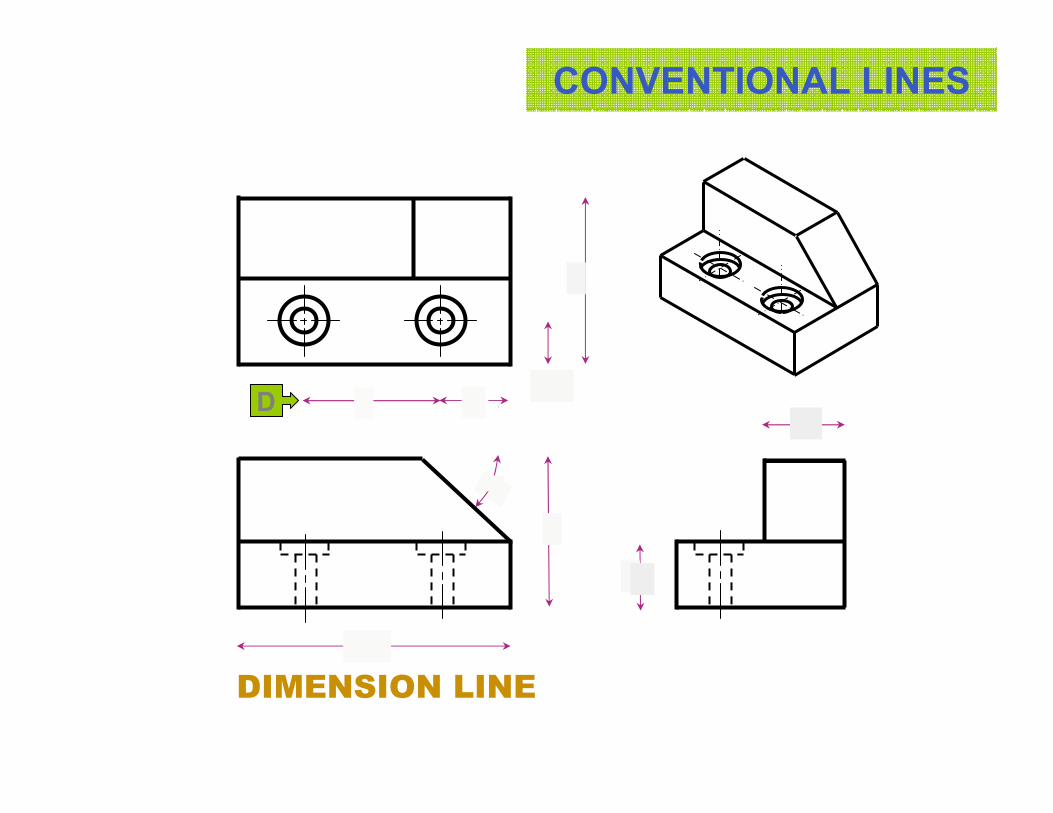
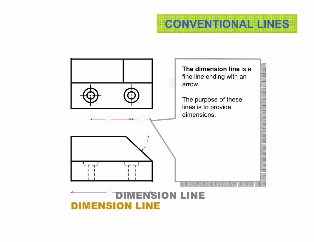
DIMENSION LINE
DIMENSION LINE
The dimension line is a
fine line ending with an
arrow.
The purpose of these
lines is to provide
dimensions.
CONVENTIONAL LINES
45
80
40 20
40°
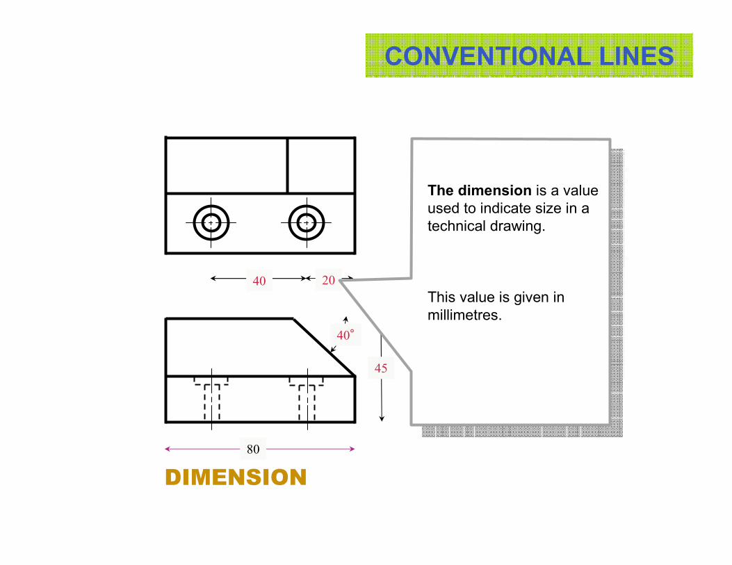
The dimension is a value
used to indicate size in a
technical drawing.
This value is given in
millimetres.
DIMENSION
CONVENTIONAL LINES
E
45
80
50
1340
24
20
40°
20
EXTENSION LINE
CONVENTIONAL LINES
45
80
50
1340
24
20
40°
20
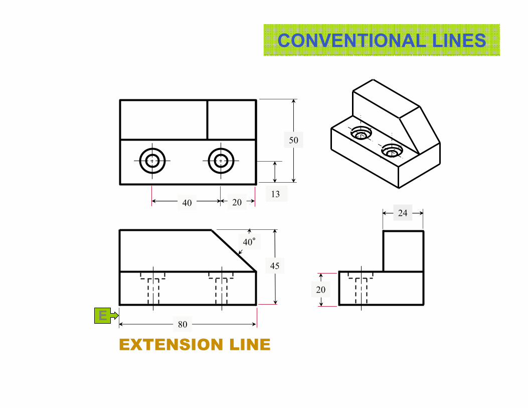
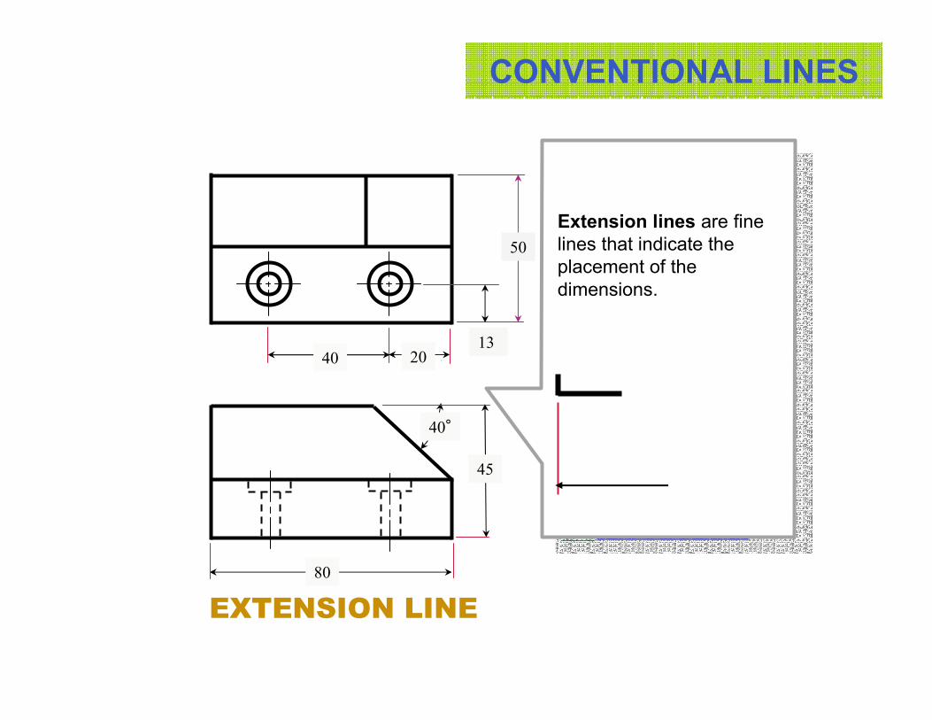
Extension lines are fine
lines that indicate the
placement of the
dimensions.
EXTENSION LINE
CONVENTIONAL LINES
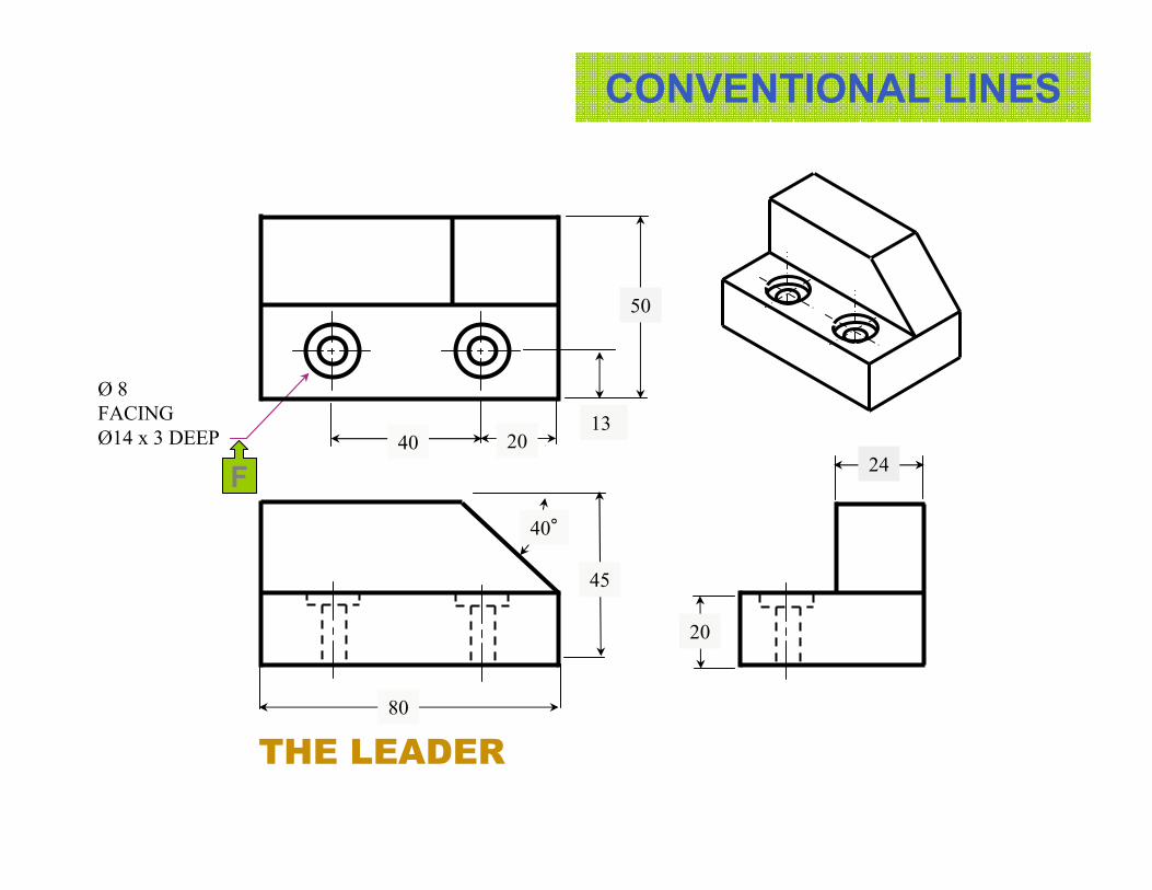
F
Ø 8
FACING
Ø14 x 3 DEEP13
4024
20
40°
20
45
50
80
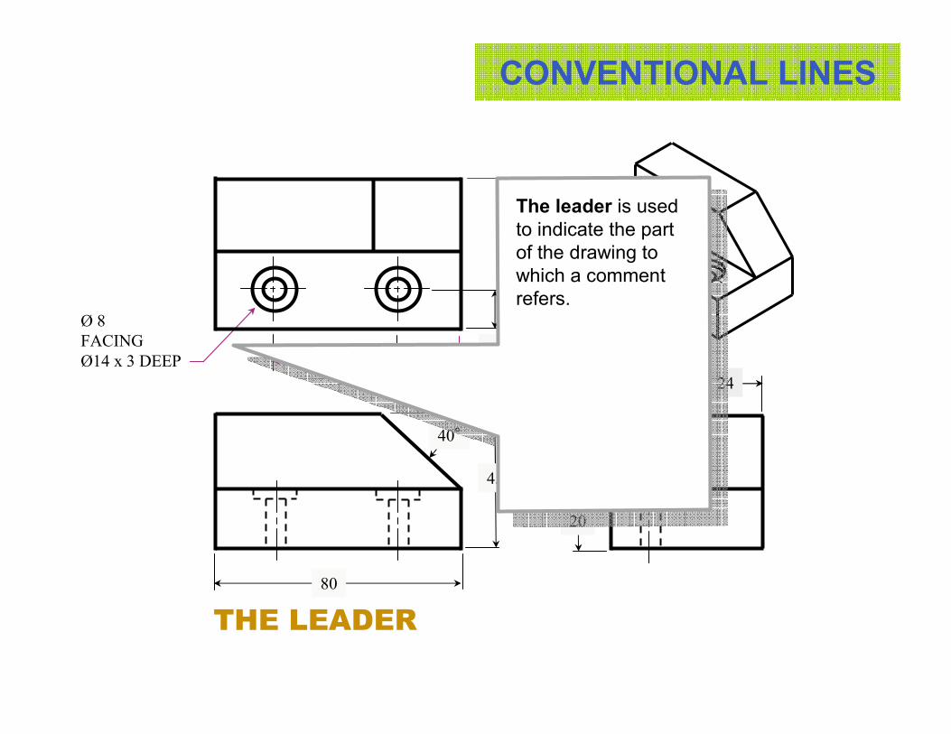
THE LEADER
CONVENTIONAL LINES
45
80
50
Ø 8
FACING
Ø14 x 3 DEEP13
4024
20
40°
20
The leader is used
to indicate the part
of the drawing to
which a comment
refers.
THE LEADER
CONVENTIONAL LINES
G
1340
24
20
40°
20
Ø 8
FACING
Ø14 x 3 DEEP
80
45
50
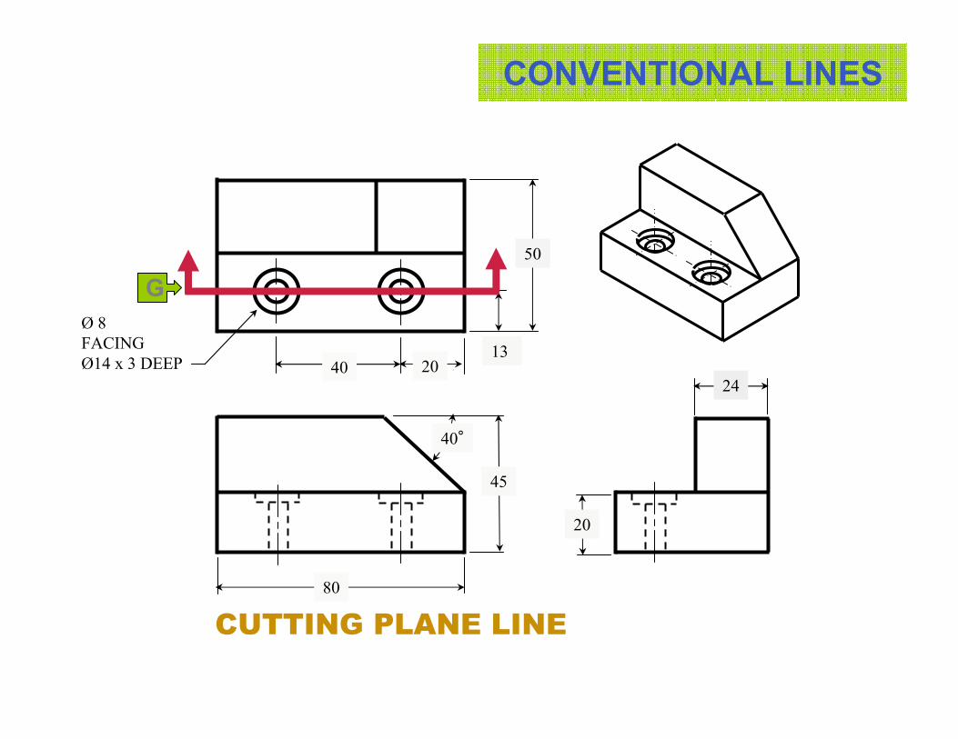
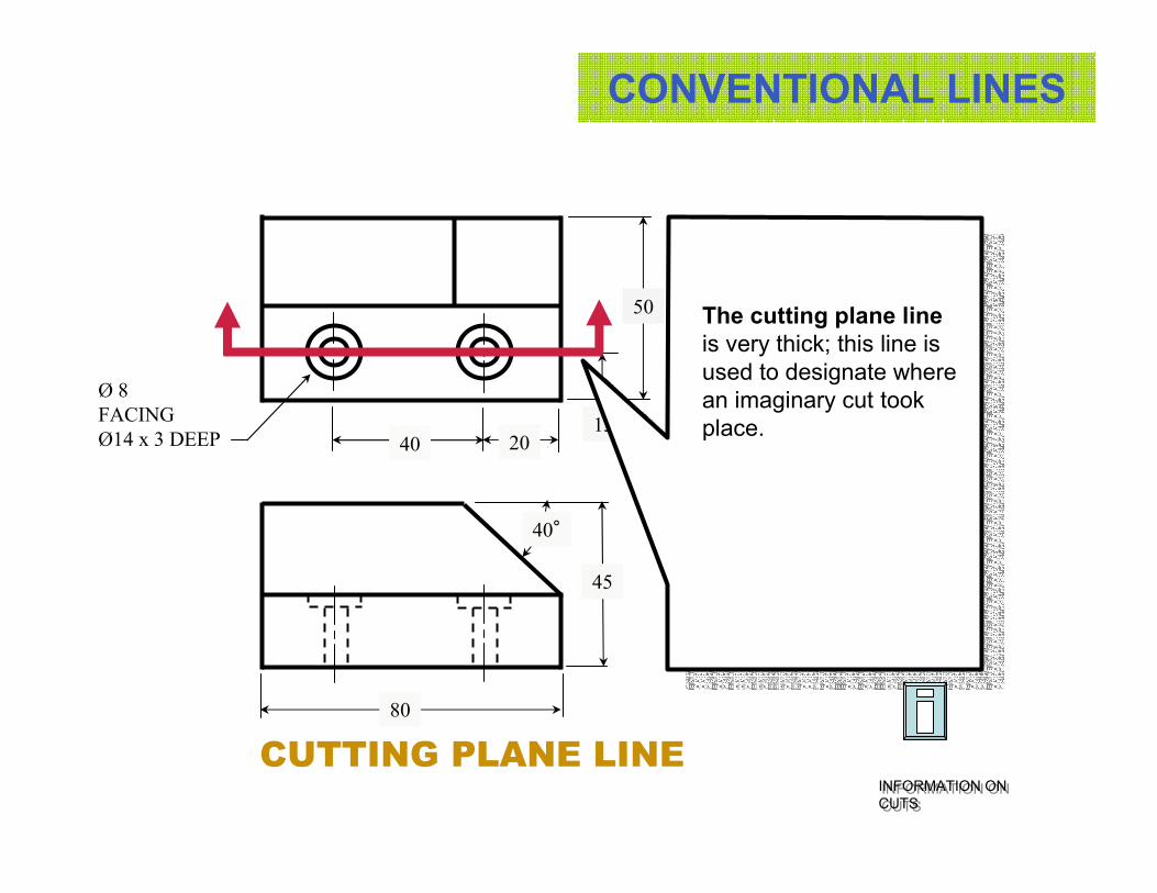
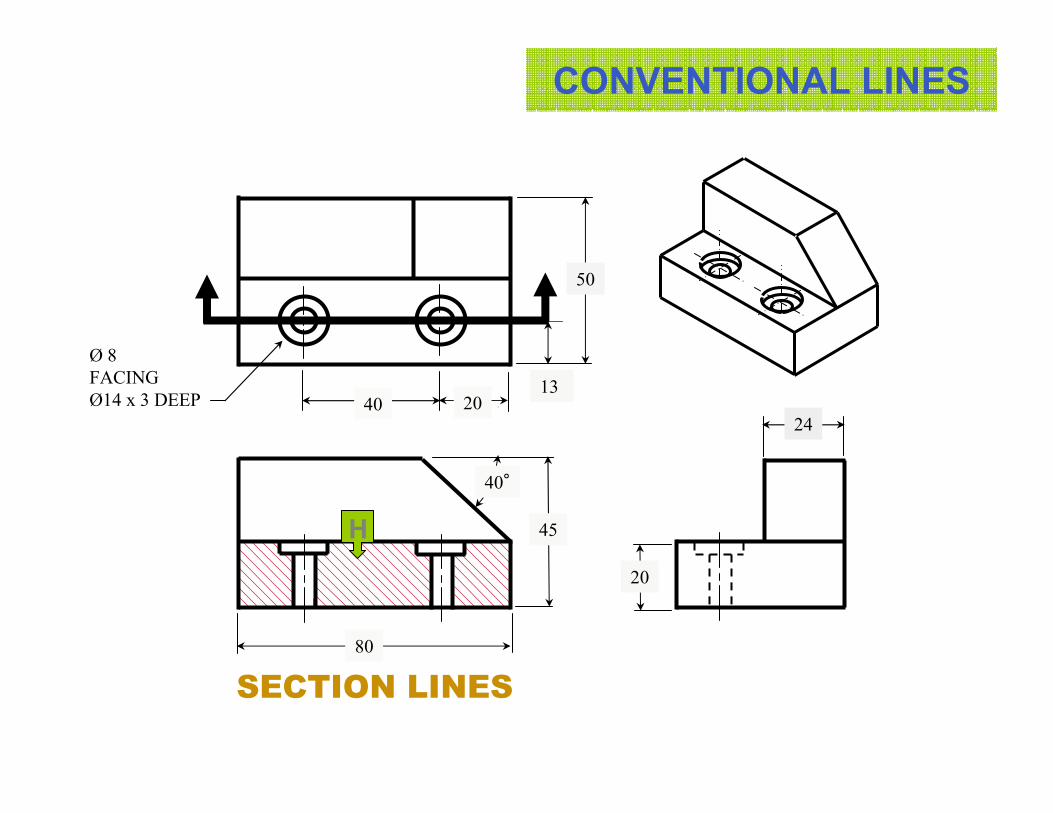
CUTTING PLANE LINE
CONVENTIONAL LINES
1340
24
20
40°
Ø 8
FACING
Ø14 x 3 DEEP
The cutting plane line
is very thick; this line is
used to designate where
an imaginary cut took
place.
INFORMATION ON
CUTS
INFORMATION ON
CUTS
80
45
50
CUTTING PLANE LINE
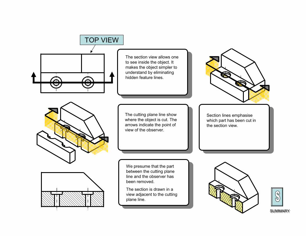
The cutting plane line show
where the object is cut. The
arrows indicate the point of
view of the observer.
The section view allows one
to see inside the object. It
makes the object simpler to
understand by eliminating
hidden feature lines.
We presume that the part
between the cutting plane
line and the observer has
been removed.
The section is drawn in a
view adjacent to the cutting
plane line.
Section lines emphasise
which part has been cut in
the section view.
SUMMARYSUMMARY
TOP VIEW
CONVENTIONAL LINES
1340
24
20
40°
20
H
Ø 8
FACING
Ø14 x 3 DEEP
50
45
80
SECTION LINES
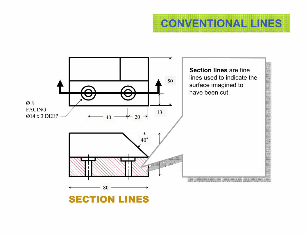
CONVENTIONAL LINES
45
1340
24
20
40°
20
Ø 8
FACING
Ø14 x 3 DEEP
Section lines are fine
lines used to indicate the
surface imagined to
have been cut.
50
80
SECTION LINES
CONVENTIONAL LINES
50
1340
24
20
40°
20
HØ 8
FACING
Ø14 x 3 DEEP
45
80
H
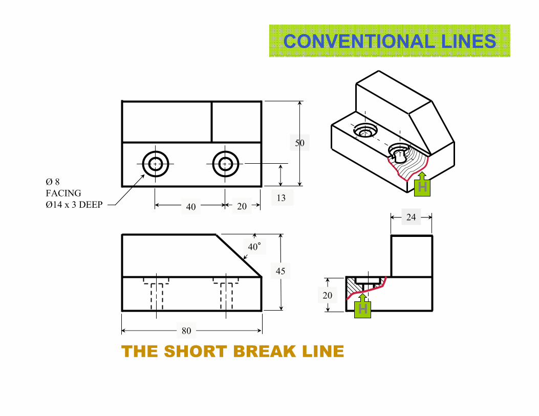
THE SHORT BREAK LINE

CONVENTIONAL LINES
45
80
50
1340
24
20
40°
20
Ø 8
FACING
Ø14 x 3 DEEP
The short break line is a
thick, irregular line used
to indicate a partial cut.
This line is drawn
freehand.
THE SHORT BREAK LINE

The long break line is a
fine line used to shorten
the view of a long part
that can not be shown full
length.
THE LONG BREAK LINE

CONVENTIONAL LINES
SUMMARY
Portrays surfaces and edges that are
hidden from view
Indicates the placement of an
imaginary cut.
Hidden feature line
A
B
C
D
E
F
G
H
NAME PURPOSE THICKNESS
J
LINE
Object line or visible
outline
Cutting plane line
Break line
Leader
Portrays visible forms.
Indicate the surface imagined to have
been cut.
Used to shorten the view of a part.
Indicates the part of a drawing to which
a note refers
Is used to indicate the dimension.Dimension line Fine
Medium
Thick
Very thick
Center linePortrays the center of a round or circular
object.
Fine
Fine
Fine
Fine
Is used to indicate the dimension.Extension lineFine
Section lines
100 %
50 %
25 %