Report No.: EMC-E20130903E
Page 1 of 56
EMC TEST REPORT For
MPP SOLAR INC
Inverter/ Charger
Model Number : PIP 4048HS
Report Number : EMC-E20130903EDate of Test : Aug. 10, 2013 to Sept. 5, 2013Date of Report : Sept. 5, 2013
Prepared for : MPP SOLAR INC Address : 4F, NO. 50-1, SECTION 1, HSIN-SHENG S. RD.
TAIPEI, TAIWAN Prepared by : MPP SOLAR INC Address : 4F, NO. 50-1, SECTION 1, HSIN-SHENG S. RD. TAIPEI, TAIWAN
Report No.: EMC-E20130903E
Page 2 of 56
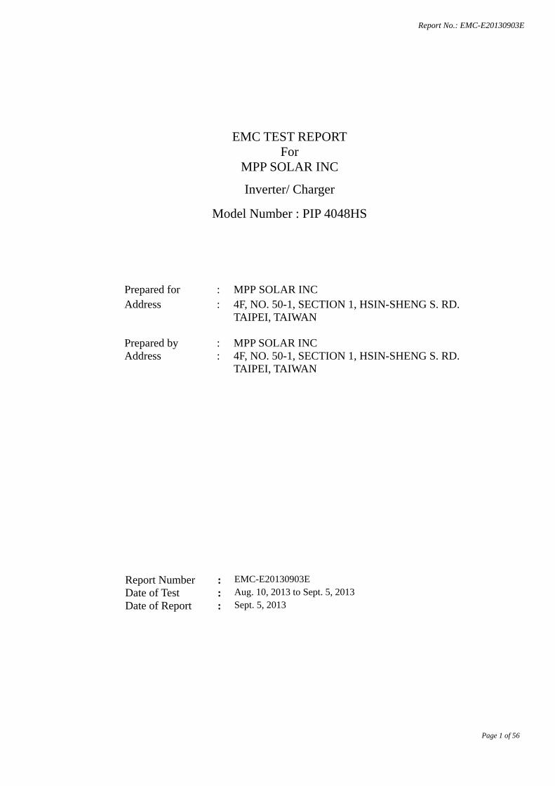
TABLE OF CONTENT Description
Page
1. GENERAL INFORMATION ............................................................................................................................ 5 1.1. Description of Device (EUT) .................................................................................................................... 5 1.2. Description of Test Facility ....................................................................................................................... 6 1.3. Measurement Uncertainty ......................................................................................................................... 6
2. MEASURING DEVICE AND TEST EQUIPMENT ....................................................................................... 7 2.1. For Mains terminals Disturbance voltage Test .......................................................................................... 7 2.2. For Radiated Emission Measurement ........................................................................................................ 7 2.3. For Electrostatic Discharge Immunity Test ............................................................................................... 7 2.4. For RF Strength Susceptibility Test .......................................................................................................... 8 2.5. For Electrical Fast Transient /Burst Immunity Test ................................................................................. 8 2.6. For Surge Immunity Test .......................................................................................................................... 8 2.7. For Injected Current Susceptibility Immunity Test .................................................................................. 8 2.8. For Voltage Dips and Interruptions Test .................................................................................................. 9
3. POWER LINE CONDUCTED EMISSION MEASUREMENT .................................................................. 10 3.1. Block Diagram of Test Setup .................................................................................................................. 10 3.2. Measuring Standard ................................................................................................................................. 10 3.3. EUT Configuration on Measurement ...................................................................................................... 10 3.4. Operating Condition of EUT ................................................................................................................... 11 3.5. Test Procedure ......................................................................................................................................... 11 3.6 Measuring Results ................................................................................................................................... 11
4. RADIATED EMISSION MEASUREMENT.................................................................................................. 12 4.1. Block Diagram of Test ............................................................................................................................ 12 4.2. Measuring Standard ................................................................................................................................. 12 4.3. Radiated Emission Limits ........................................................................................................................ 13 4.4. EUT Configuration on Test ..................................................................................................................... 13 4.5. Operating Condition of EUT ................................................................................................................... 13 4.6. Test Procedure ......................................................................................................................................... 13 4.7. Measuring Results ................................................................................................................................... 13
5. HARMONIC CURRENT EMISSION MEASUREMENT ............................................................................... 14 5.1 Block Diagram of Test Setup .................................................................................................................. 14 5.2 Measuring Standard ................................................................................................................................. 14 5.3 Operation Condition of EUT ................................................................................................................... 14 5.4 Measuring Results ................................................................................................................................... 14
6. VOLTAGE FLUCTUATION AND FLICKER MEASUREMENT .................................................................. 15 6.1 Block Diagram of Test Setup .................................................................................................................. 15 6.2 Measuring Standard ................................................................................................................................. 15 6.3 Operation Condition of EUT ................................................................................................................... 15 6.4 Measuring Results ................................................................................................................................... 15
7. ELECTROSTATIC DISCHARGE IMMUNITY TEST ................................................................................... 16 7.1 Block Diagram of Test Setup .................................................................................................................. 16 7.2 Test Standard ........................................................................................................................................... 16 7.3 Severity Levels ........................................................................................................................................ 16 7.4 EUT Configuration .................................................................................................................................. 16 7.5 Operating Condition of EUT ................................................................................................................... 16 7.6 Test Procedure ......................................................................................................................................... 17 7.7 Test Results .............................................................................................................................................. 17
8. RF FIELD STRENGTH SUSCEPTIBILITY TEST ......................................................................................... 19 8.1 Block Diagram of Test............................................................................................................................. 19 8.2 Test Standard ........................................................................................................................................... 19 8.3 Severity Levels ........................................................................................................................................ 20
Report No.: EMC-E20130903E
Page 3 of 56
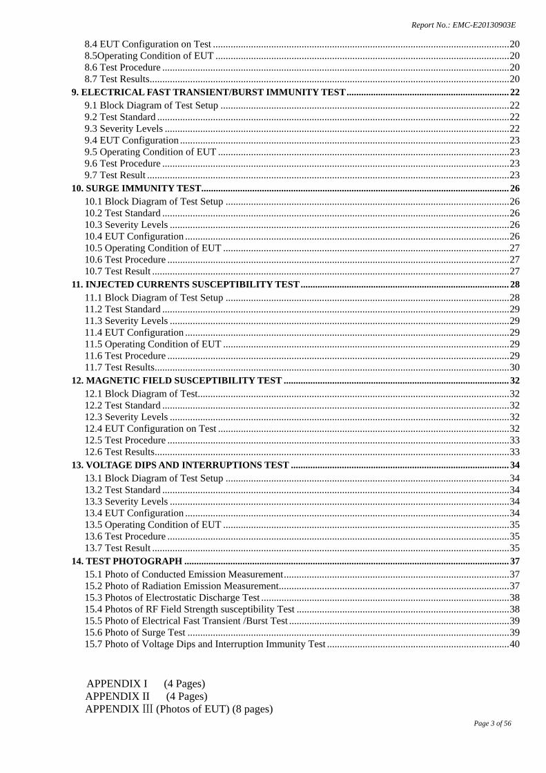
8.4 EUT Configuration on Test ..................................................................................................................... 20 8.5Operating Condition of EUT .................................................................................................................... 20 8.6 Test Procedure ......................................................................................................................................... 20 8.7 Test Results .............................................................................................................................................. 20
9. ELECTRICAL FAST TRANSIENT/BURST IMMUNITY TEST ................................................................... 22 9.1 Block Diagram of Test Setup .................................................................................................................. 22 9.2 Test Standard ........................................................................................................................................... 22 9.3 Severity Levels ........................................................................................................................................ 22 9.4 EUT Configuration .................................................................................................................................. 23 9.5 Operating Condition of EUT ................................................................................................................... 23 9.6 Test Procedure ......................................................................................................................................... 23 9.7 Test Result ............................................................................................................................................... 23
10. SURGE IMMUNITY TEST ............................................................................................................................... 26 10.1 Block Diagram of Test Setup ................................................................................................................ 26 10.2 Test Standard ......................................................................................................................................... 26 10.3 Severity Levels ...................................................................................................................................... 26 10.4 EUT Configuration ................................................................................................................................ 26 10.5 Operating Condition of EUT ................................................................................................................. 27 10.6 Test Procedure ....................................................................................................................................... 27 10.7 Test Result ............................................................................................................................................. 27
11. INJECTED CURRENTS SUSCEPTIBILITY TEST ...................................................................................... 28 11.1 Block Diagram of Test Setup ................................................................................................................ 28 11.2 Test Standard ......................................................................................................................................... 29 11.3 Severity Levels ...................................................................................................................................... 29 11.4 EUT Configuration ................................................................................................................................ 29 11.5 Operating Condition of EUT ................................................................................................................. 29 11.6 Test Procedure ....................................................................................................................................... 29 11.7 Test Results ............................................................................................................................................ 30
12. MAGNETIC FIELD SUSCEPTIBILITY TEST ............................................................................................. 32 12.1 Block Diagram of Test........................................................................................................................... 32 12.2 Test Standard ......................................................................................................................................... 32 12.3 Severity Levels ...................................................................................................................................... 32 12.4 EUT Configuration on Test ................................................................................................................... 32 12.5 Test Procedure ....................................................................................................................................... 33 12.6 Test Results ............................................................................................................................................ 33
13. VOLTAGE DIPS AND INTERRUPTIONS TEST .......................................................................................... 34 13.1 Block Diagram of Test Setup ................................................................................................................ 34 13.2 Test Standard ......................................................................................................................................... 34 13.3 Severity Levels ...................................................................................................................................... 34 13.4 EUT Configuration ................................................................................................................................ 34 13.5 Operating Condition of EUT ................................................................................................................. 35 13.6 Test Procedure ....................................................................................................................................... 35 13.7 Test Result ............................................................................................................................................. 35
14. TEST PHOTOGRAPH ...................................................................................................................................... 37 15.1 Photo of Conducted Emission Measurement ......................................................................................... 37 15.2 Photo of Radiation Emission Measurement ........................................................................................... 37 15.3 Photos of Electrostatic Discharge Test .................................................................................................. 38 15.4 Photos of RF Field Strength susceptibility Test .................................................................................... 38 15.5 Photo of Electrical Fast Transient /Burst Test ....................................................................................... 39 15.6 Photo of Surge Test ............................................................................................................................... 39 15.7 Photo of Voltage Dips and Interruption Immunity Test ........................................................................ 40
APPENDIX I (4 Pages) APPENDIX II (4 Pages)
APPENDIX Ⅲ (Photos of EUT) (8 pages)
Report No.: EMC-E20130903E
Page 4 of 56
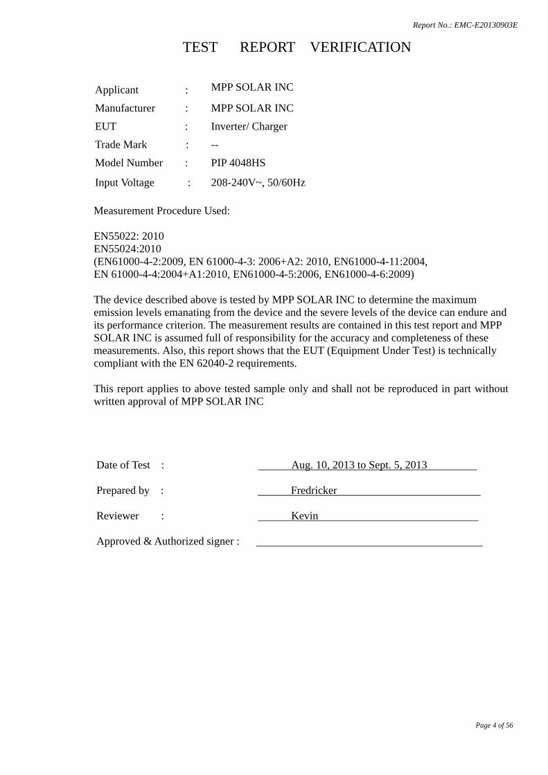
TEST REPORT VERIFICATION
Applicant : MPP SOLAR INC
Manufacturer : MPP SOLAR INC
EUT : Inverter/ Charger
Trade Mark : --
Model Number : PIP 4048HS
Input Voltage : 208-240V~, 50/60Hz
Measurement Procedure Used: EN55022: 2010 EN55024:2010 (EN61000-4-2:2009, EN 61000-4-3: 2006+A2: 2010, EN61000-4-11:2004, EN 61000-4-4:2004+A1:2010, EN61000-4-5:2006, EN61000-4-6:2009) The device described above is tested by MPP SOLAR INC to determine the maximum emission levels emanating from the device and the severe levels of the device can endure and its performance criterion. The measurement results are contained in this test report and MPP SOLAR INC is assumed full of responsibility for the accuracy and completeness of these measurements. Also, this report shows that the EUT (Equipment Under Test) is technically compliant with the EN 62040-2 requirements. This report applies to above tested sample only and shall not be reproduced in part without written approval of MPP SOLAR INC
Date of Test : Aug. 10, 2013 to Sept. 5, 2013 Prepared by : Fredricker Reviewer : Kevin Approved & Authorized signer :
Report No.: EMC-E20130903E
Page 5 of 56
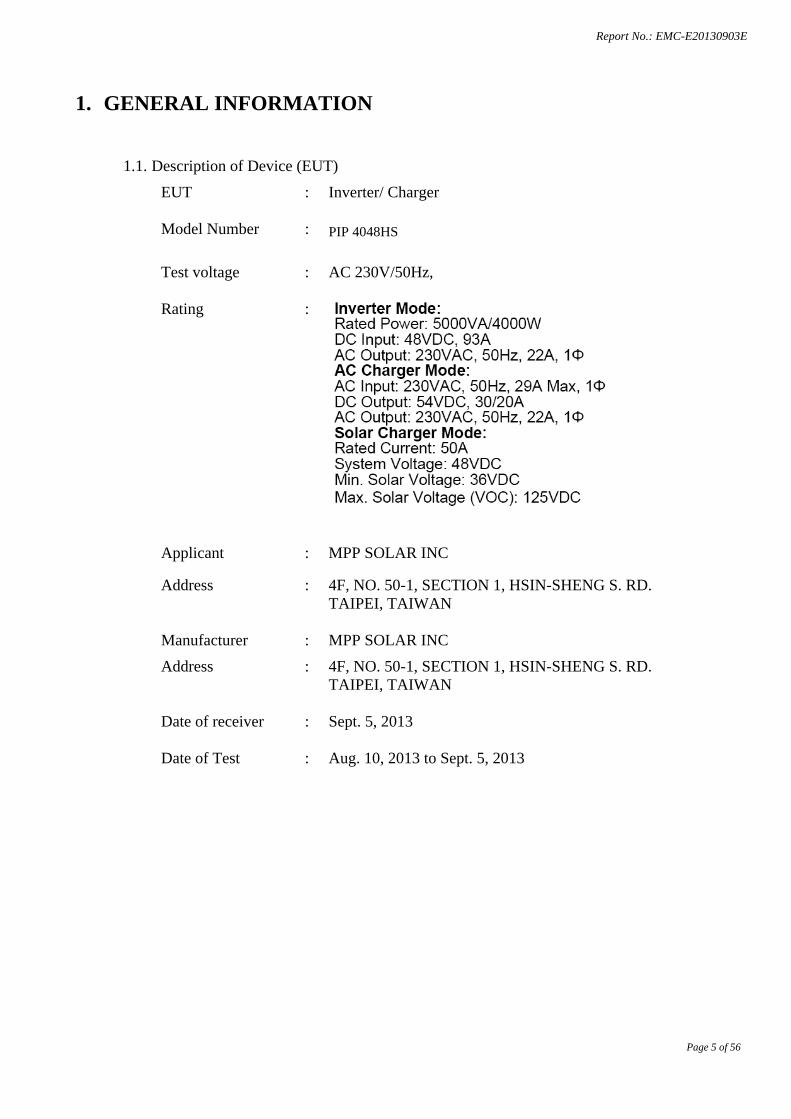
1. GENERAL INFORMATION
1.1. Description of Device (EUT)
EUT : Inverter/ Charger Model Number : PIP 4048HS Test voltage : AC 230V/50Hz, Rating :
Applicant : MPP SOLAR INC
Address : 4F, NO. 50-1, SECTION 1, HSIN-SHENG S. RD. TAIPEI, TAIWAN
Manufacturer : MPP SOLAR INC Address : 4F, NO. 50-1, SECTION 1, HSIN-SHENG S. RD.
TAIPEI, TAIWAN Date of receiver : Sept. 5, 2013 Date of Test : Aug. 10, 2013 to Sept. 5, 2013

Report No.: EMC-E20130903E
Page 6 of 56
1.2. Description of Test Facility Site Description EMC Lab. :
Name of Firm : Site Location :
1.3. Measurement Uncertainty Radiation Uncertainty : Ur = ±2.7dB Conduction Uncertainty : Uc = ±3.4dB
Report No.: EMC-E20130903E
Page 7 of 56
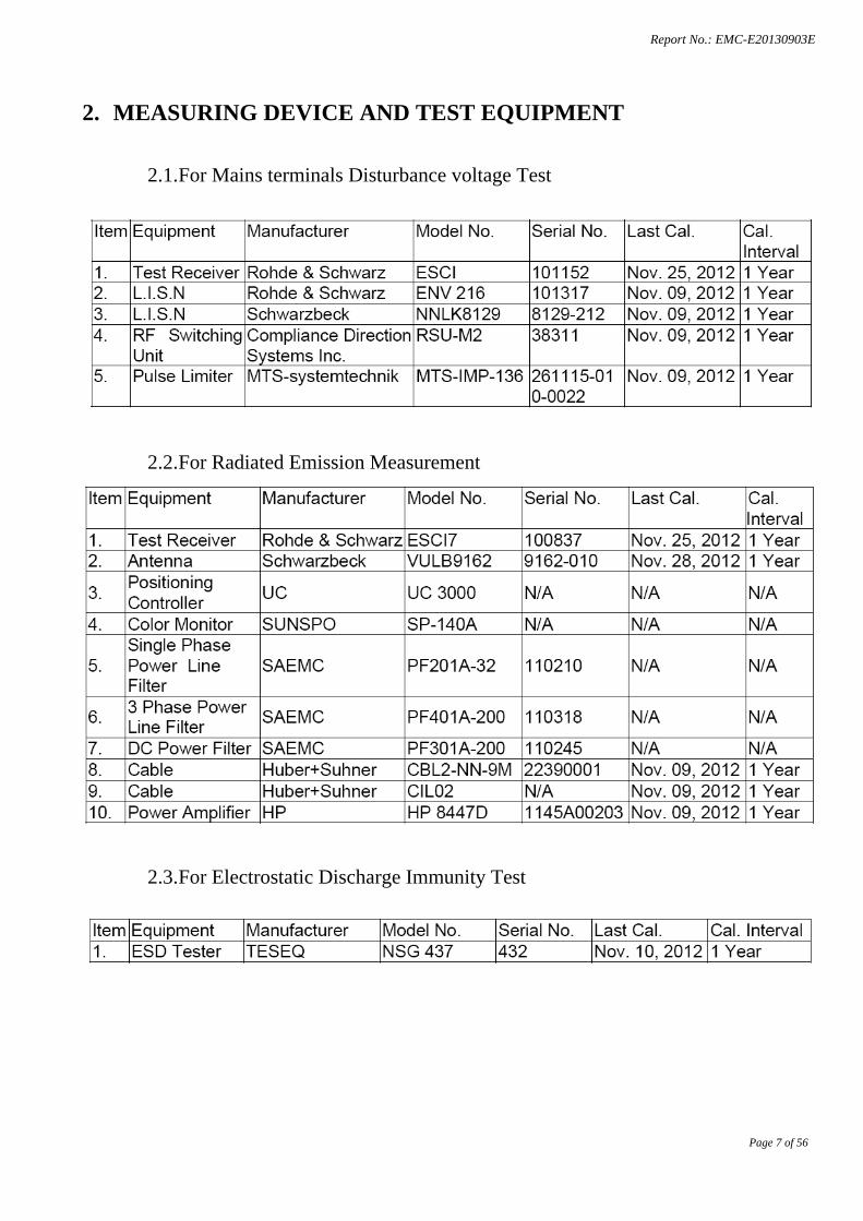
2. MEASURING DEVICE AND TEST EQUIPMENT
2.1. For Mains terminals Disturbance voltage Test
2.2. For Radiated Emission Measurement
2.3. For Electrostatic Discharge Immunity Test
Report No.: EMC-E20130903E
Page 8 of 56
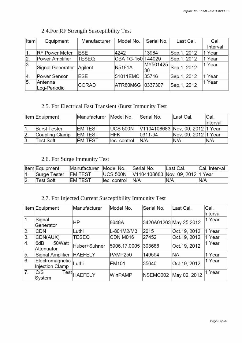
2.4. For RF Strength Susceptibility Test
2.5. For Electrical Fast Transient /Burst Immunity Test
2.6. For Surge Immunity Test
2.7. For Injected Current Susceptibility Immunity Test
Report No.: EMC-E20130903E
Page 9 of 56
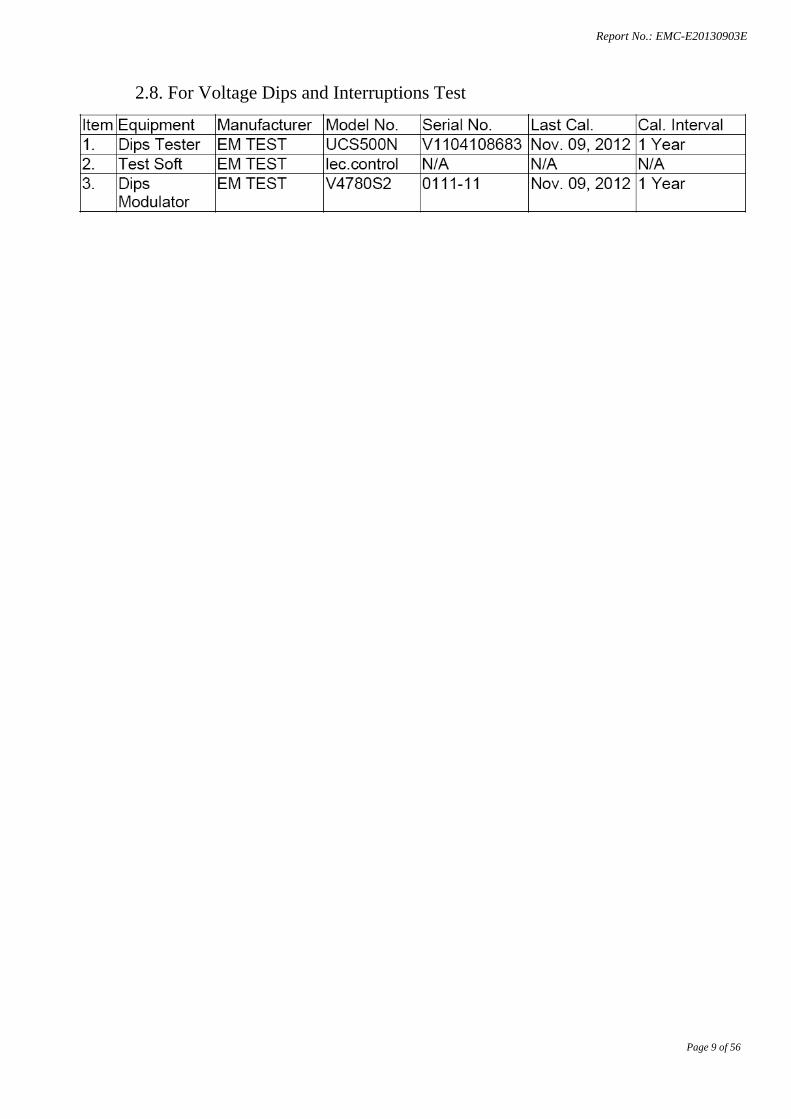
2.8. For Voltage Dips and Interruptions Test
Report No.: EMC-E20130903E
Page 10 of 56
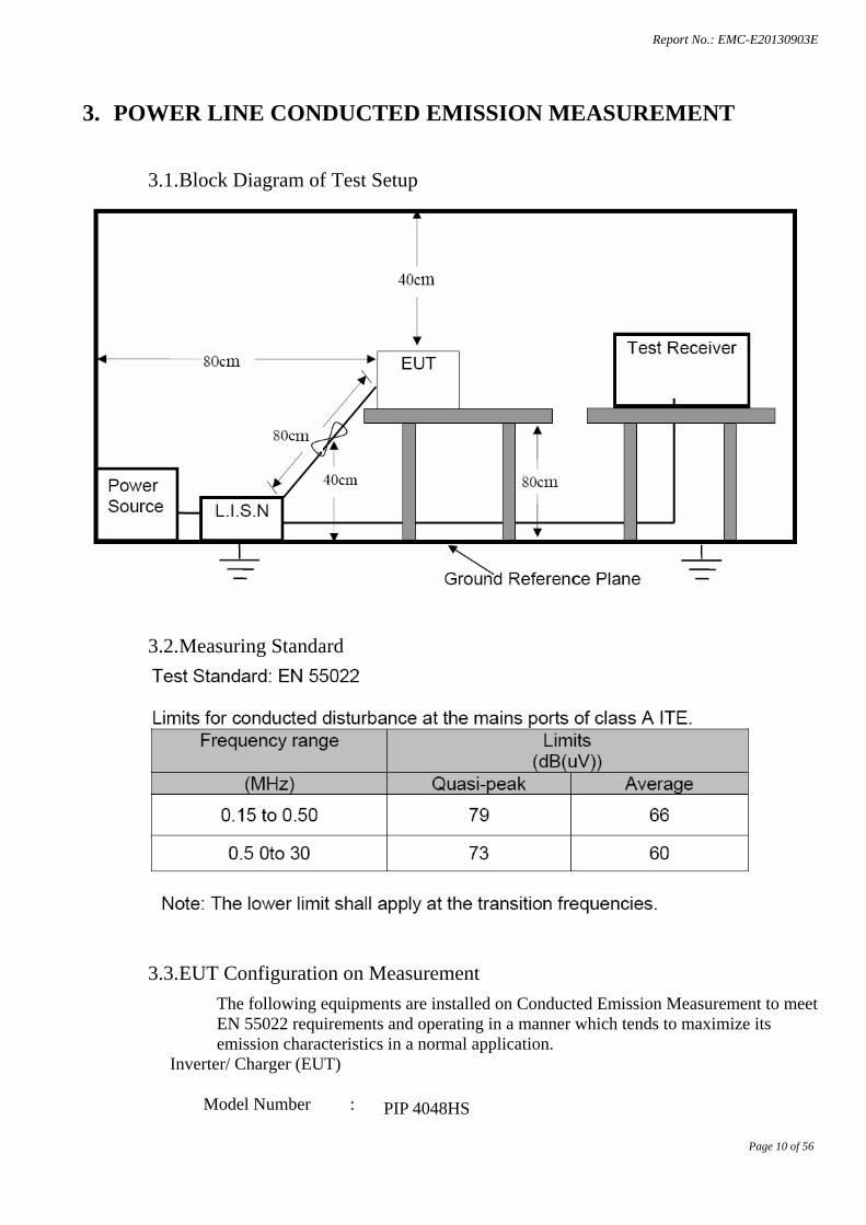
3. POWER LINE CONDUCTED EMISSION MEASUREMENT
3.1. Block Diagram of Test Setup
3.2. Measuring Standard
3.3. EUT Configuration on Measurement The following equipments are installed on Conducted Emission Measurement to meet EN 55022 requirements and operating in a manner which tends to maximize its emission characteristics in a normal application.
Inverter/ Charger (EUT)
Model Number : PIP 4048HS
Report No.: EMC-E20130903E
Page 11 of 56
Serial Number : N/A
3.4. Operating Condition of EUT 3.4.1.Setup the EUT as shown on Section 3.1.
3.4.2.Turn on the power of all equipments.
3.4.3.Let the EUT work in measuring mode (Line mode/ Battery mode) and measure it.
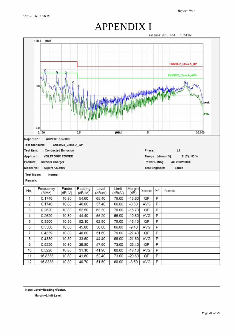
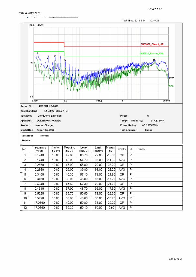
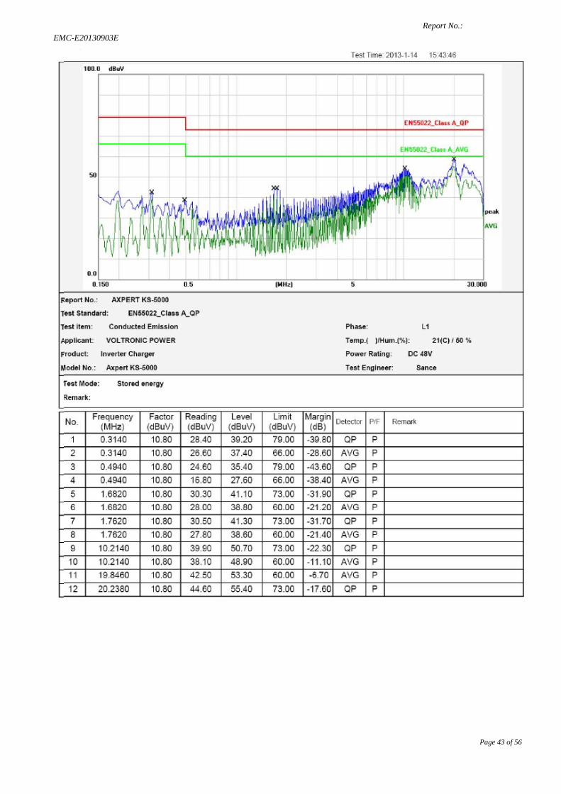
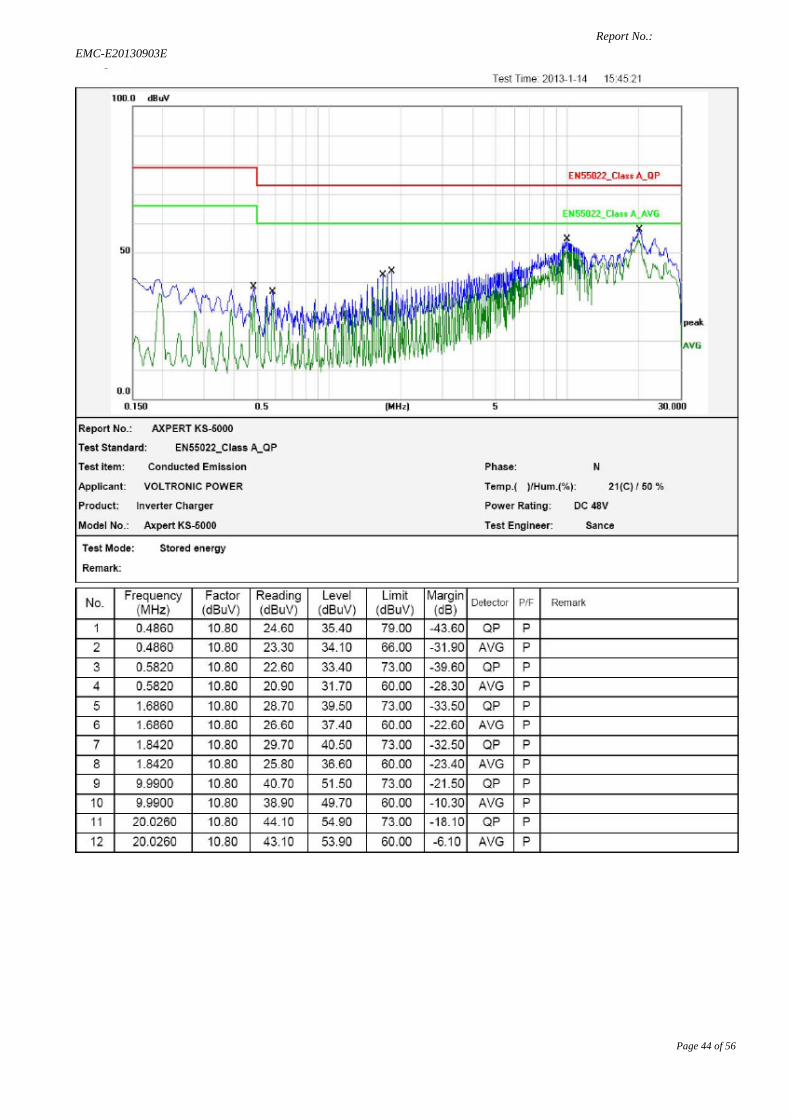
3.5. Test Procedure The EUT is put on the plane 0.8m high above the ground by insulating support and connected to the AC mains through Line Impedance Stability Network (L.I.S.N). This provided a 50ohm coupling impedance for the tested equipments. Both sides of AC line are investigated to find out the maximum conducted emission according to the EN 62040-2 regulations during conducted emission measurement. The bandwidth of the field strength meter is set at 9KHz in 150KHz~30MHz and 200Hz in 9KHz~150KHz. The frequency range from 150kHz to 30MHz is investigated All the scanning waveform is put in Appendix I.
3.6 Measuring Results PASS. Please reference to APPENDIX I
Report No.: EMC-E20130903E
Page 12 of 56
4. RADIATED EMISSION MEASUREMENT
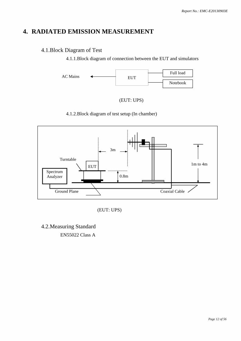
4.1. Block Diagram of Test 4.1.1.Block diagram of connection between the EUT and simulators
(EUT: UPS)
4.1.2.Block diagram of test setup (In chamber)
(EUT: UPS)
4.2. Measuring Standard EN55022 Class A
1m to 4m
Spectrum Analyzer
EUT
3m
0.8m
Turntable
Coaxial Cable Ground Plane
AC Mains
EUT Full load
Notebook
Report No.: EMC-E20130903E
Page 13 of 56
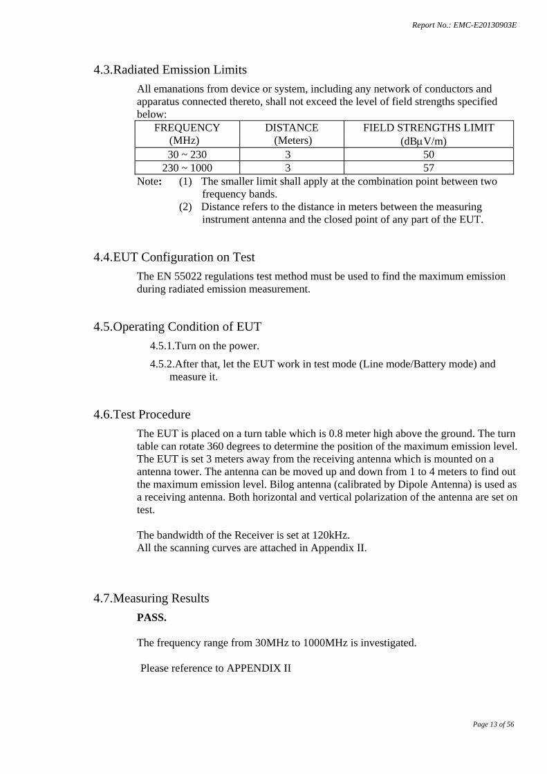
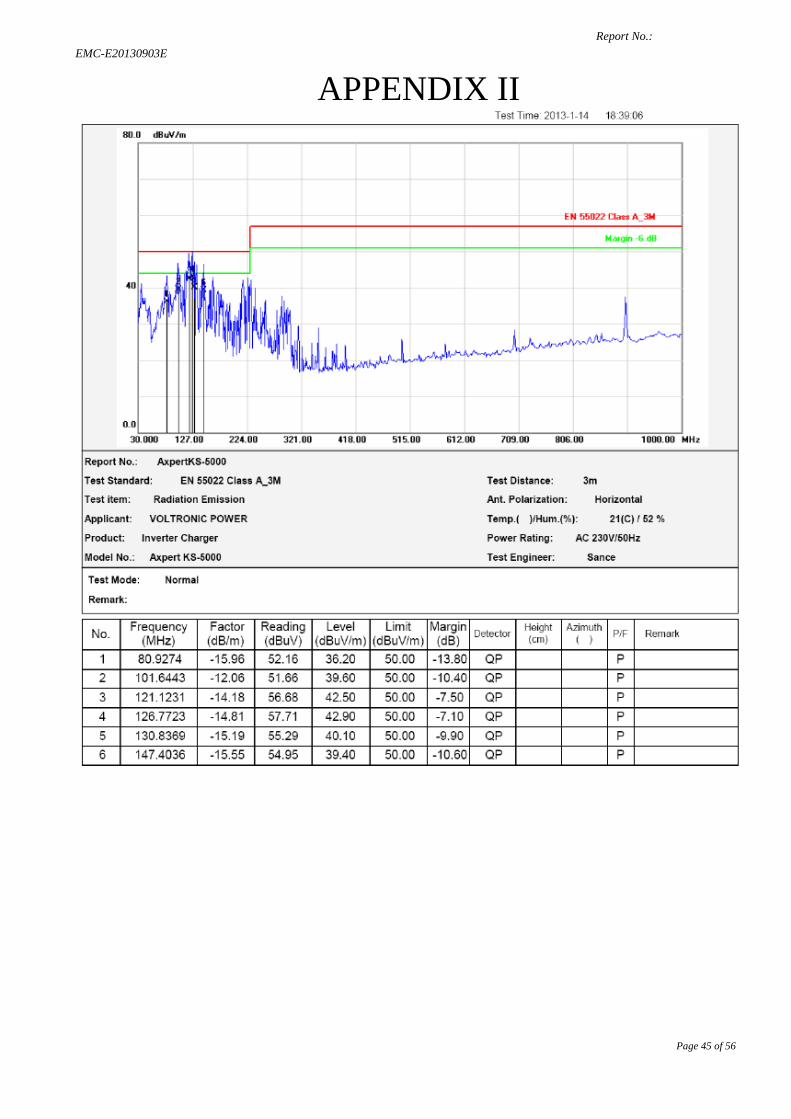
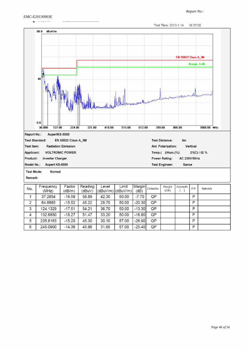
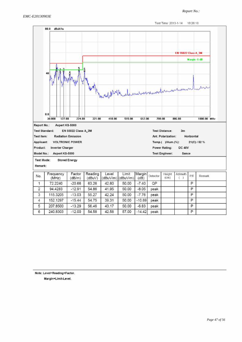
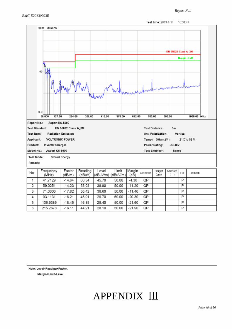
4.3. Radiated Emission Limits All emanations from device or system, including any network of conductors and apparatus connected thereto, shall not exceed the level of field strengths specified below:
FREQUENCY DISTANCE FIELD STRENGTHS LIMIT (MHz) (Meters) (dBμV/m) 30 ~ 230 3 50
230 ~ 1000 3 57 Note: (1) The smaller limit shall apply at the combination point between two
frequency bands. (2) Distance refers to the distance in meters between the measuring
instrument antenna and the closed point of any part of the EUT.
4.4. EUT Configuration on Test The EN 55022 regulations test method must be used to find the maximum emission during radiated emission measurement.
4.5. Operating Condition of EUT 4.5.1.Turn on the power.
4.5.2.After that, let the EUT work in test mode (Line mode/Battery mode) and measure it.
4.6. Test Procedure The EUT is placed on a turn table which is 0.8 meter high above the ground. The turn table can rotate 360 degrees to determine the position of the maximum emission level. The EUT is set 3 meters away from the receiving antenna which is mounted on a antenna tower. The antenna can be moved up and down from 1 to 4 meters to find out the maximum emission level. Bilog antenna (calibrated by Dipole Antenna) is used as a receiving antenna. Both horizontal and vertical polarization of the antenna are set on test. The bandwidth of the Receiver is set at 120kHz. All the scanning curves are attached in Appendix II.
4.7. Measuring Results PASS. The frequency range from 30MHz to 1000MHz is investigated.
Please reference to APPENDIX II
Report No.: EMC-E20130903E
Page 14 of 56
5. HARMONIC CURRENT EMISSION MEASUREMENT
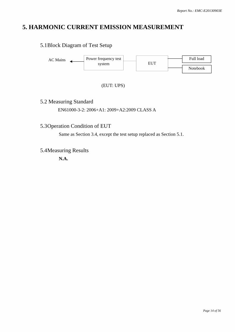
5.1 Block Diagram of Test Setup
(EUT: UPS)
5.2 Measuring Standard EN61000-3-2: 2006+A1: 2009+A2:2009 CLASS A
5.3 Operation Condition of EUT Same as Section 3.4, except the test setup replaced as Section 5.1.
5.4 Measuring Results N.A.
Power frequency test system
AC Mains EUT
Full load
Notebook
Report No.: EMC-E20130903E
Page 15 of 56
6. VOLTAGE FLUCTUATION AND FLICKER MEASUREMENT
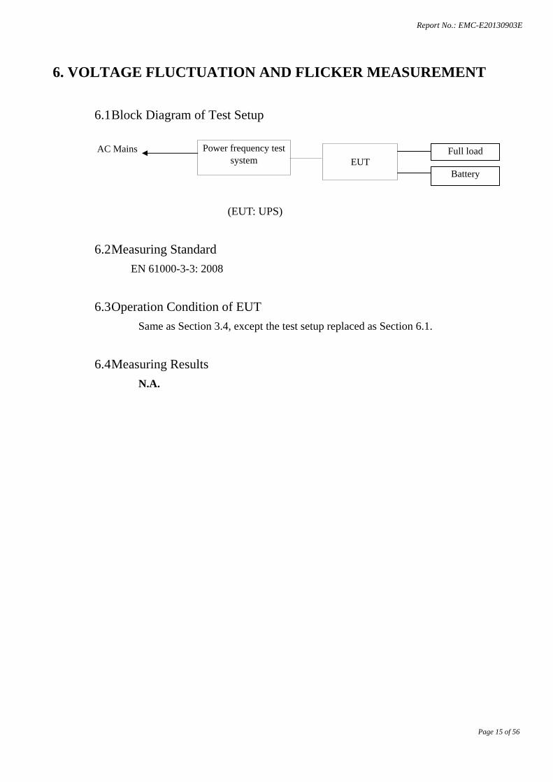
6.1 Block Diagram of Test Setup
(EUT: UPS)
6.2 Measuring Standard EN 61000-3-3: 2008
6.3 Operation Condition of EUT Same as Section 3.4, except the test setup replaced as Section 6.1.
6.4 Measuring Results N.A.
Power frequency test system
AC Mains EUT
Full load
Battery
Report No.: EMC-E20130903E
Page 16 of 56
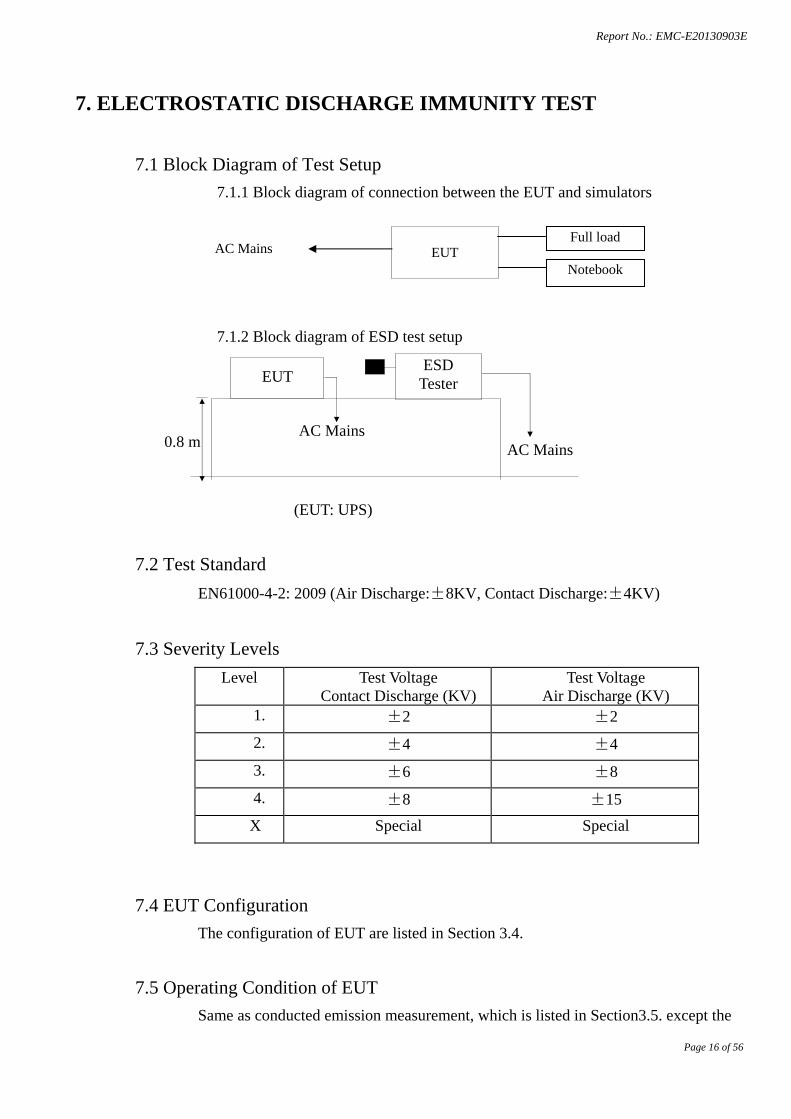
7. ELECTROSTATIC DISCHARGE IMMUNITY TEST
7.1 Block Diagram of Test Setup 7.1.1 Block diagram of connection between the EUT and simulators
7.1.2 Block diagram of ESD test setup
(EUT: UPS)
7.2 Test Standard EN61000-4-2: 2009 (Air Discharge:±8KV, Contact Discharge:±4KV)
7.3 Severity Levels Level Test Voltage
Contact Discharge (KV) Test Voltage
Air Discharge (KV) 1. ±2 ±2
2. ±4 ±4
3. ±6 ±8
4. ±8 ±15
X Special Special
7.4 EUT Configuration The configuration of EUT are listed in Section 3.4.
7.5 Operating Condition of EUT Same as conducted emission measurement, which is listed in Section3.5. except the
EUT
AC Mains AC Mains
ESD Tester
0.8 m
AC Mains
EUT Full load
Notebook
Report No.: EMC-E20130903E
Page 17 of 56
test set up replaced by Section 7.1.
7.6 Test Procedure 7.6.1 Air Discharge:
This test is done on a non-conductive surface. The round discharge tip of the discharge electrode shall be approached as fast as possible to touch the EUT. After each discharge, the discharge electrode shall be removed from the EUT. The generator is then re-triggered for a new single discharge and repeated 10 times for each pre-selected test point. This procedure shall be repeated until all the air discharge completed
7.6.2 Contact Discharge:
All the procedure shall be same as Section 7.6.1. except that the tip of the discharge electrode shall touch the EUT before the discharge switch is operated.
7.6.3 Indirect discharge for horizontal coupling plane
At least 10 single discharges(in the most sensitive polarity) shall be applied at the front edge of each HCP opposite the center point of each unit(if applicable) of the EUT and 0.1m from the front of the EUT. The long axis of the discharge electrode shall be in the plane of the HCP and perpendicular to its front edge during the discharge.
7.6.4 Indirect discharge for vertical coupling plane
At least 10 single discharge (in the most sensitive polarity) shall be applied to the center of one vertical edge of the coupling plane. The coupling plane, of dimensions 0.5m X 0.5m, is placed parallel to, and positioned at a distance of 0.1m from the EUT. Discharges shall be applied to the coupling plane, with this plane in sufficient different positions that the four faces of the EUT are completely illuminated.
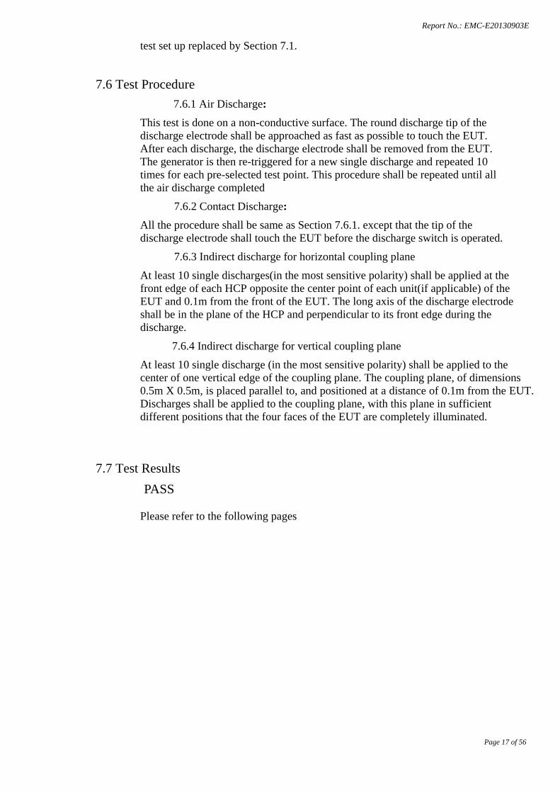
7.7 Test Results PASS
Please refer to the following pages
Report No.: EMC-E20130903E
Page 18 of 56
Electrostatic Discharge Test Result
Report No.: EMC-E20130903E
Page 19 of 56
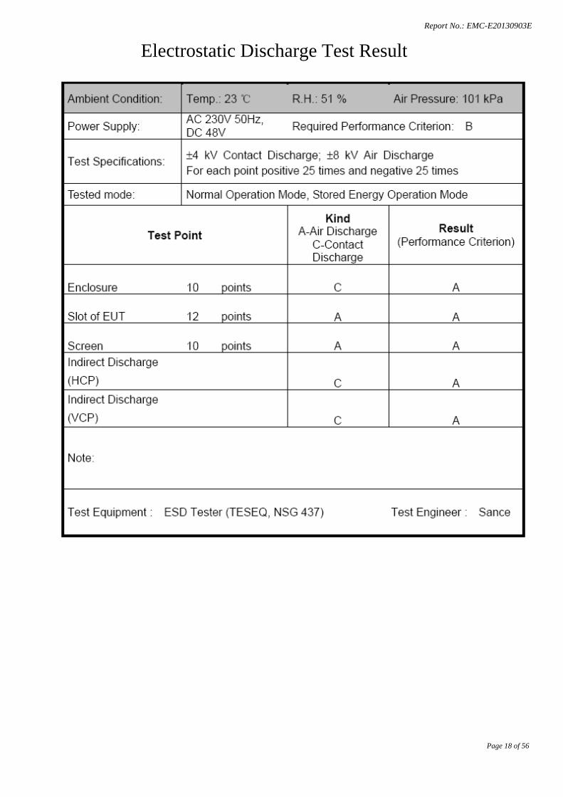
8. RF FIELD STRENGTH SUSCEPTIBILITY TEST
8.1 Block Diagram of Test 8.1.1 Block diagram of connection between the EUT and Load
(EUT: UPS)
8.1.2 Block diagram of RS test setup
(EUT: UPS)
8.2 Test Standard EN61000-4-3: 2006+A1:2008+A2:2010 (3V / m)
0.8m
Power Amp Signal Generator
EUT Monitoring by using a camera
PC Controller to control S.G. & PA as well as forward power
7x4x3Chamber
EUT & Support Units
3 meter
1.5 meter
AC Mains
EUT Full load
Notebook
Report No.: EMC-E20130903E
Page 20 of 56
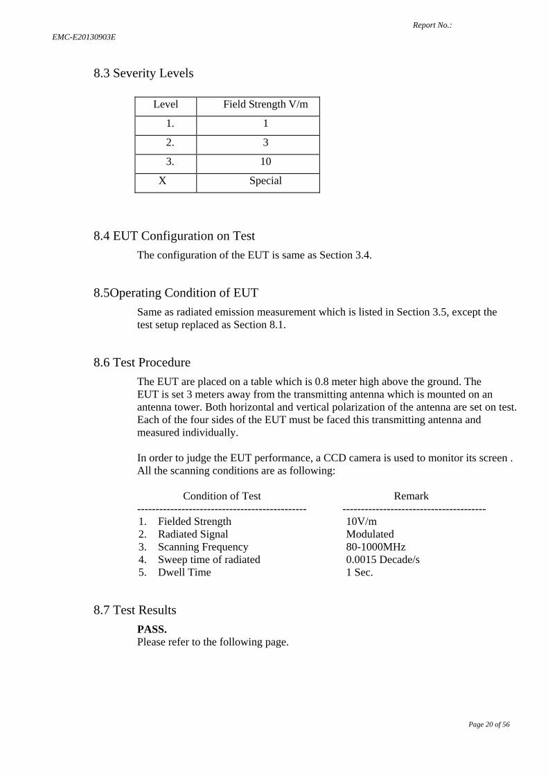
8.3 Severity Levels
Level Field Strength V/m
1. 1
2. 3
3. 10
X Special
8.4 EUT Configuration on Test The configuration of the EUT is same as Section 3.4.
8.5Operating Condition of EUT Same as radiated emission measurement which is listed in Section 3.5, except the test setup replaced as Section 8.1.
8.6 Test Procedure The EUT are placed on a table which is 0.8 meter high above the ground. The EUT is set 3 meters away from the transmitting antenna which is mounted on an antenna tower. Both horizontal and vertical polarization of the antenna are set on test. Each of the four sides of the EUT must be faced this transmitting antenna and measured individually. In order to judge the EUT performance, a CCD camera is used to monitor its screen . All the scanning conditions are as following:
Condition of Test Remark ---------------------------------------------- --------------------------------------- 1. Fielded Strength 2. Radiated Signal 3. Scanning Frequency 4. Sweep time of radiated 5. Dwell Time
10V/m Modulated 80-1000MHz 0.0015 Decade/s 1 Sec.
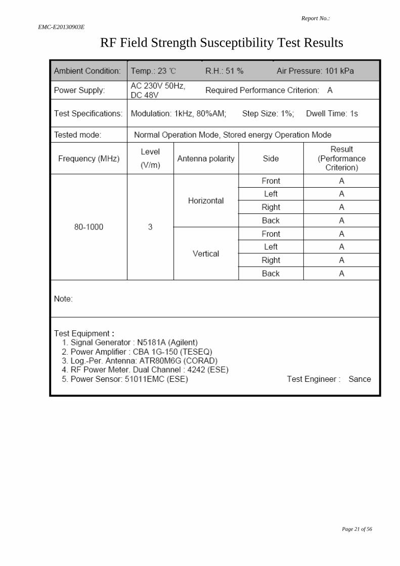
8.7 Test Results PASS. Please refer to the following page.
Report No.: EMC-E20130903E
Page 21 of 56
RF Field Strength Susceptibility Test Results
Report No.: EMC-E20130903E
Page 22 of 56
9. ELECTRICAL FAST TRANSIENT/BURST IMMUNITY TEST
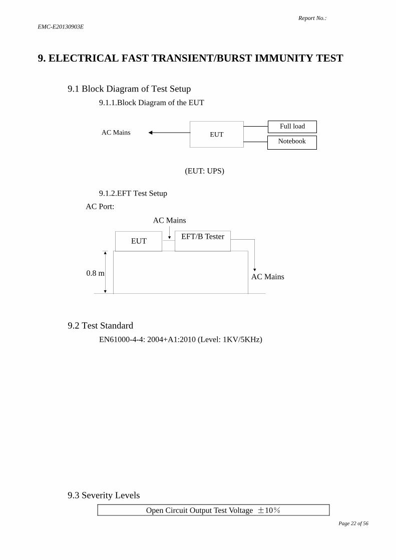
9.1 Block Diagram of Test Setup 9.1.1.Block Diagram of the EUT
(EUT: UPS)
9.1.2.EFT Test Setup
AC Port:
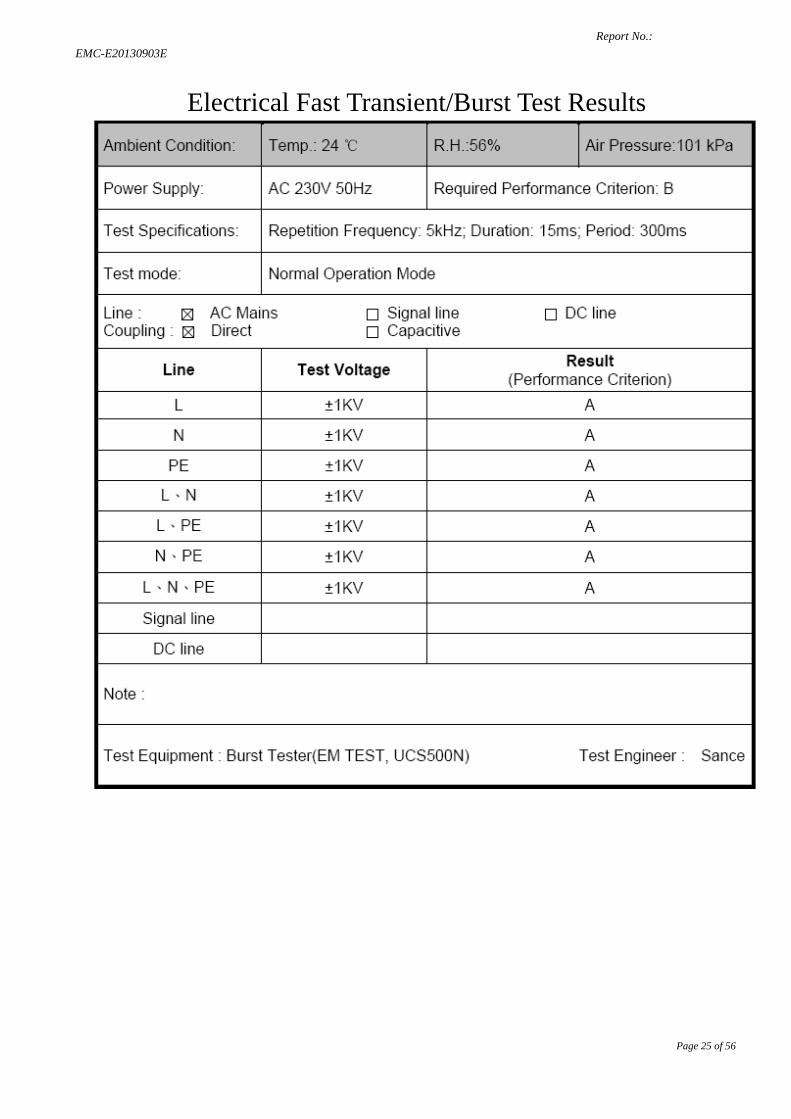
9.2 Test Standard EN61000-4-4: 2004+A1:2010 (Level: 1KV/5KHz)
9.3 Severity Levels Open Circuit Output Test Voltage ±10%
AC Mains
EUT
AC Mains
EFT/B Tester
0.8 m
AC Mains
EUT Full load
Notebook
Report No.: EMC-E20130903E
Page 23 of 56
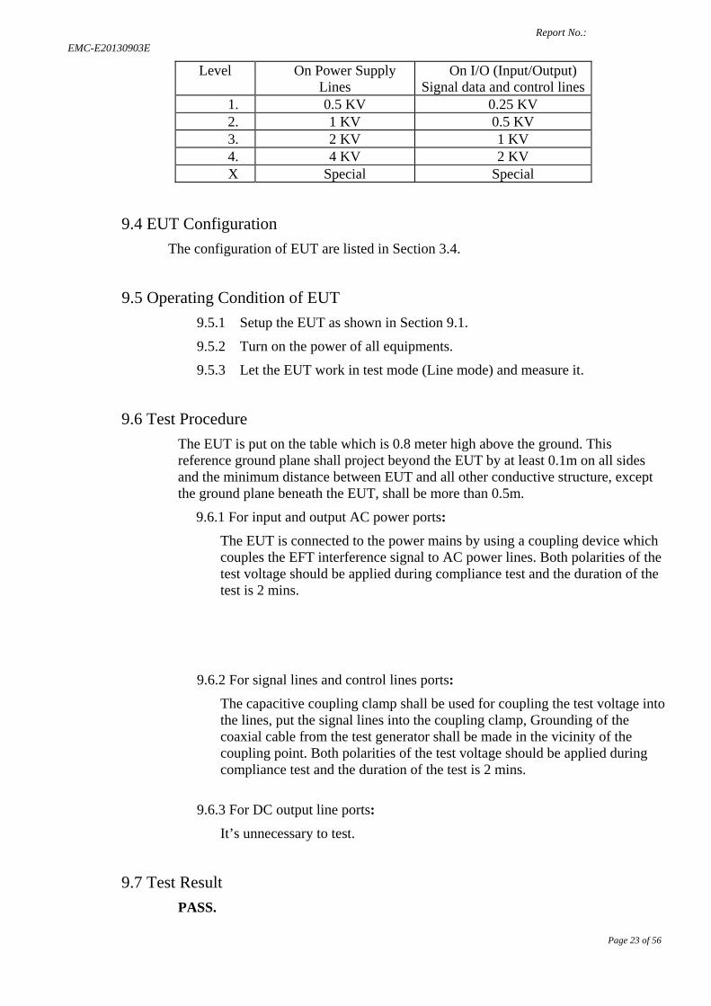
Level On Power Supply Lines
On I/O (Input/Output) Signal data and control lines
1. 0.5 KV 0.25 KV 2. 1 KV 0.5 KV 3. 2 KV 1 KV 4. 4 KV 2 KV
X Special Special
9.4 EUT Configuration The configuration of EUT are listed in Section 3.4.
9.5 Operating Condition of EUT 9.5.1 Setup the EUT as shown in Section 9.1.
9.5.2 Turn on the power of all equipments.
9.5.3 Let the EUT work in test mode (Line mode) and measure it.
9.6 Test Procedure The EUT is put on the table which is 0.8 meter high above the ground. This reference ground plane shall project beyond the EUT by at least 0.1m on all sides and the minimum distance between EUT and all other conductive structure, except the ground plane beneath the EUT, shall be more than 0.5m.
9.6.1 For input and output AC power ports:
The EUT is connected to the power mains by using a coupling device which couples the EFT interference signal to AC power lines. Both polarities of the test voltage should be applied during compliance test and the duration of the test is 2 mins.
9.6.2 For signal lines and control lines ports:
The capacitive coupling clamp shall be used for coupling the test voltage into the lines, put the signal lines into the coupling clamp, Grounding of the coaxial cable from the test generator shall be made in the vicinity of the coupling point. Both polarities of the test voltage should be applied during compliance test and the duration of the test is 2 mins.
9.6.3 For DC output line ports:
It’s unnecessary to test.
9.7 Test Result PASS.

Report No.: EMC-E20130903E
Page 24 of 56
Please refer to the following page.
Report No.: EMC-E20130903E
Page 25 of 56
Electrical Fast Transient/Burst Test Results
Report No.: EMC-E20130903E
Page 26 of 56
10. SURGE IMMUNITY TEST
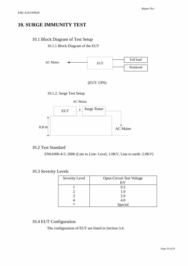
10.1 Block Diagram of Test Setup 10.1.1 Block Diagram of the EUT
(EUT: UPS)
10.1.2. Surge Test Setup
10.2 Test Standard EN61000-4-5: 2006 (Line to Line: Level, 1.0KV, Line to earth: 2.0KV)
10.3 Severity Levels Severity Level Open-Circuit Test Voltage
KV 1 2 3 4 *
0.5 1.0 2.0 4.0
Special
10.4 EUT Configuration The configuration of EUT are listed in Section 3.4.
0.8 m AC Mains
EUT
AC Mains
Surge Tester
AC Mains
EUT Full load
Notebook
Report No.: EMC-E20130903E
Page 27 of 56
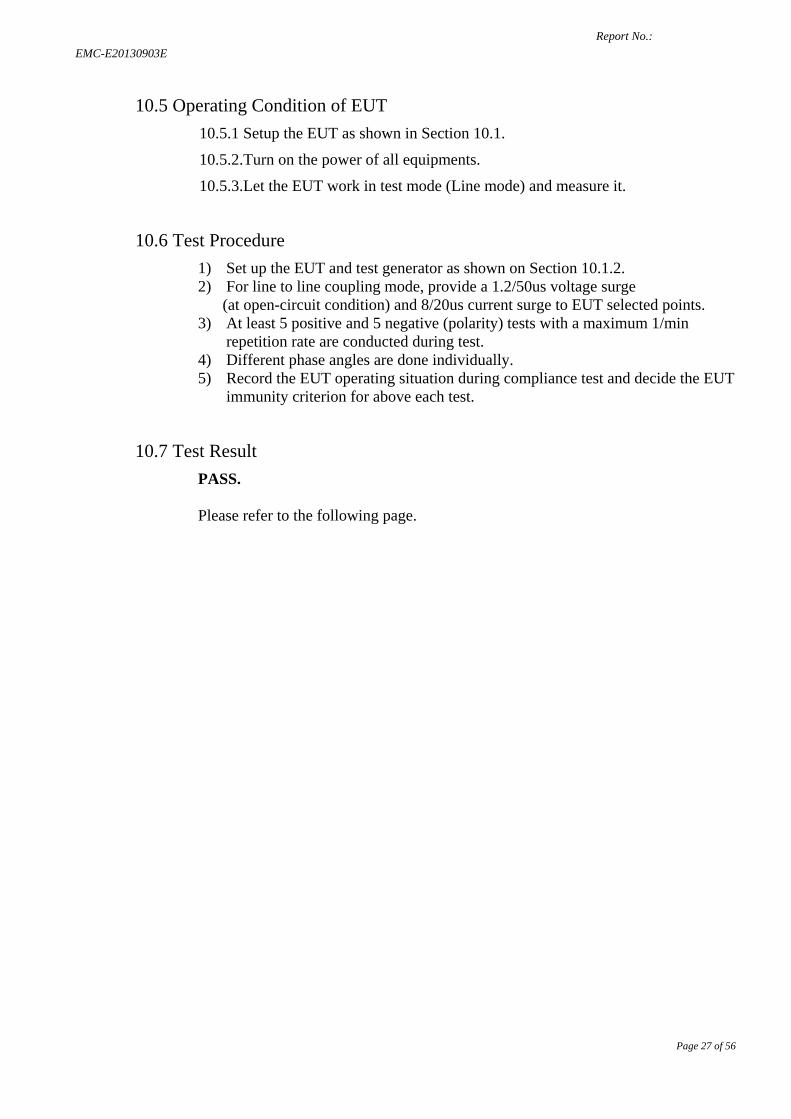
10.5 Operating Condition of EUT 10.5.1 Setup the EUT as shown in Section 10.1.
10.5.2.Turn on the power of all equipments.
10.5.3.Let the EUT work in test mode (Line mode) and measure it.
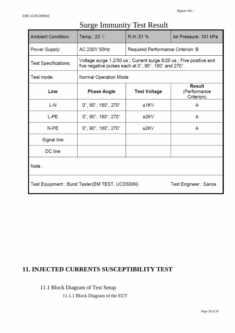
10.6 Test Procedure 1) Set up the EUT and test generator as shown on Section 10.1.2. 2) For line to line coupling mode, provide a 1.2/50us voltage surge (at open-circuit condition) and 8/20us current surge to EUT selected points. 3) At least 5 positive and 5 negative (polarity) tests with a maximum 1/min
repetition rate are conducted during test. 4) Different phase angles are done individually. 5) Record the EUT operating situation during compliance test and decide the EUT
immunity criterion for above each test.
10.7 Test Result PASS. Please refer to the following page.
Report No.: EMC-E20130903E
Page 28 of 56
Surge Immunity Test Result
11. INJECTED CURRENTS SUSCEPTIBILITY TEST
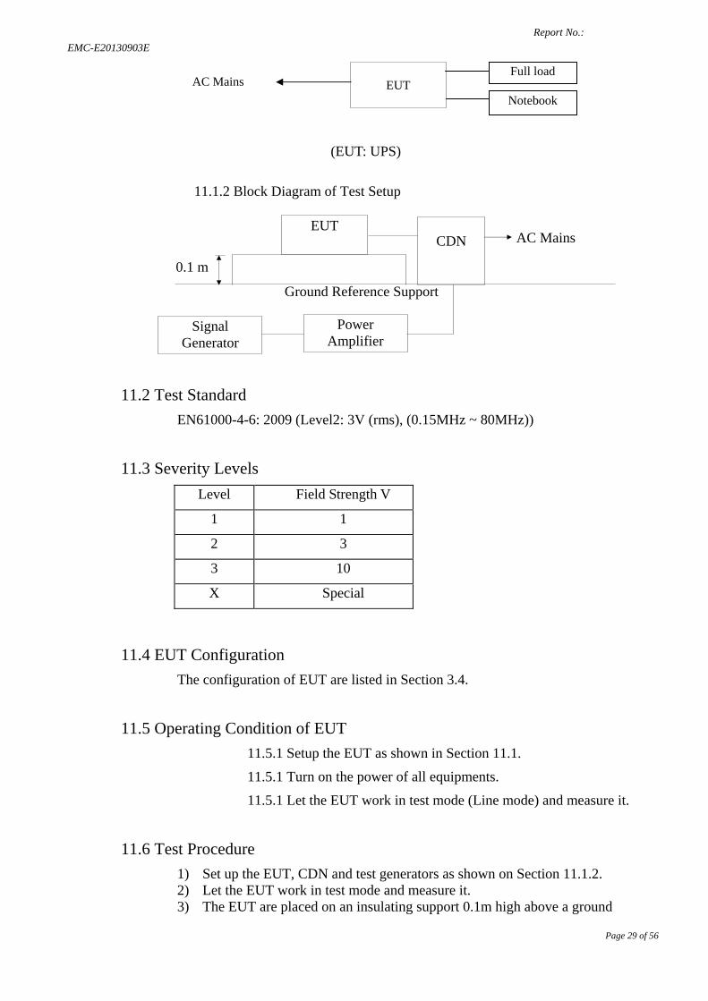
11.1 Block Diagram of Test Setup 11.1.1 Block Diagram of the EUT
Report No.: EMC-E20130903E
Page 29 of 56
(EUT: UPS)
11.1.2 Block Diagram of Test Setup
11.2 Test Standard EN61000-4-6: 2009 (Level2: 3V (rms), (0.15MHz ~ 80MHz))
11.3 Severity Levels
11.4 EUT Configuration The configuration of EUT are listed in Section 3.4.
11.5 Operating Condition of EUT 11.5.1 Setup the EUT as shown in Section 11.1.
11.5.1 Turn on the power of all equipments.
11.5.1 Let the EUT work in test mode (Line mode) and measure it.
11.6 Test Procedure 1) Set up the EUT, CDN and test generators as shown on Section 11.1.2. 2) Let the EUT work in test mode and measure it. 3) The EUT are placed on an insulating support 0.1m high above a ground
Level Field Strength V
1 1
2 3
3 10
X Special
Ground Reference Support
EUT CDN AC Mains
Signal Generator
Power Amplifier
0.1 m
AC Mains
EUT Full load
Notebook
Report No.: EMC-E20130903E
Page 30 of 56
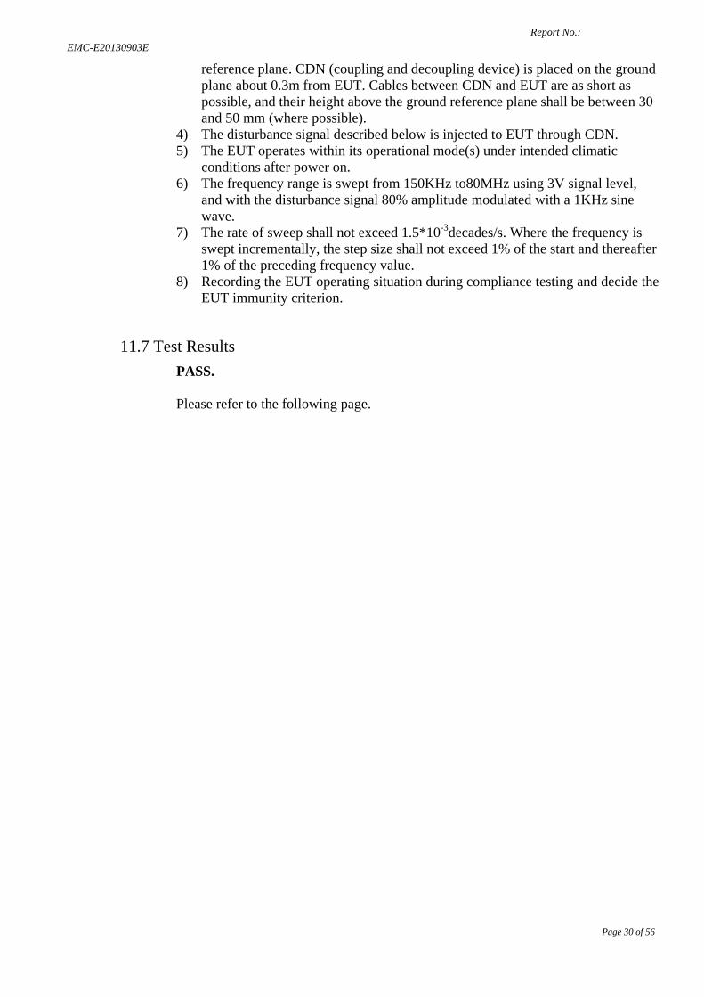
reference plane. CDN (coupling and decoupling device) is placed on the ground plane about 0.3m from EUT. Cables between CDN and EUT are as short as possible, and their height above the ground reference plane shall be between 30 and 50 mm (where possible).
4) The disturbance signal described below is injected to EUT through CDN. 5) The EUT operates within its operational mode(s) under intended climatic
conditions after power on. 6) The frequency range is swept from 150KHz to80MHz using 3V signal level,
and with the disturbance signal 80% amplitude modulated with a 1KHz sine wave.
7) The rate of sweep shall not exceed 1.5*10-3decades/s. Where the frequency is swept incrementally, the step size shall not exceed 1% of the start and thereafter 1% of the preceding frequency value.
8) Recording the EUT operating situation during compliance testing and decide the EUT immunity criterion.
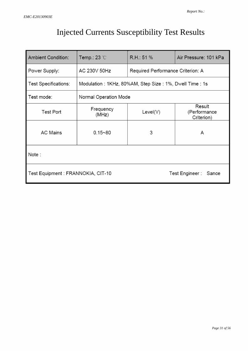
11.7 Test Results PASS. Please refer to the following page.
Report No.: EMC-E20130903E
Page 31 of 56
Injected Currents Susceptibility Test Results
Report No.: EMC-E20130903E
Page 32 of 56
12. MAGNETIC FIELD SUSCEPTIBILITY TEST
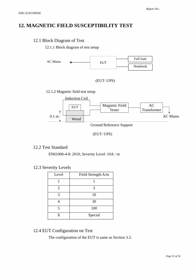
12.1 Block Diagram of Test 12.1.1 Block diagram of test setup
(EUT: UPS)
12.1.2 Magnetic field test setup
(EUT: UPS)
12.2 Test Standard EN61000-4-8: 2010, Severity Level: 10A / m
12.3 Severity Levels Level Field Strength A/m
1 1
2 3
3 10
4 30
5 100
X Special
12.4 EUT Configuration on Test The configuration of the EUT is same as Section 3.3.
Ground Reference Support
EUT
AC Mains 0.1 m
Magnetic Field Tester
AC Transformer
Wood
Induction Coil
AC Mains
EUT Full load
Notebook
Report No.: EMC-E20130903E
Page 33 of 56
12.5 Test Procedure The EUT is placed in the middle of a induction coil (1*1m), under which is a 1*1*0.1m (high) table, this small table is also placed on a larger table, 0.8 m above the ground. Both horizontal and vertical polarization of the induction coil is set on test, so that each side of the EUT is affected by the magnetic field. Also can reach the same aim by change the position of the EUT.
12.6 Test Results N.A.
Report No.: EMC-E20130903E
Page 34 of 56
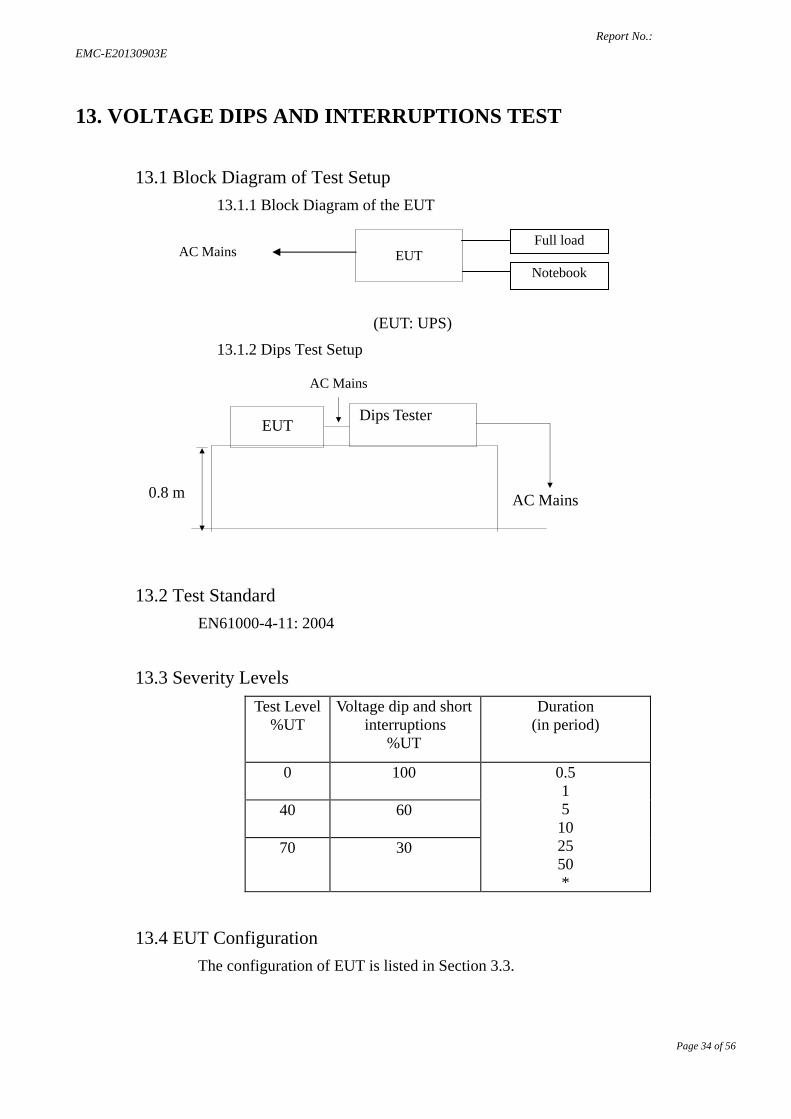
13. VOLTAGE DIPS AND INTERRUPTIONS TEST
13.1 Block Diagram of Test Setup 13.1.1 Block Diagram of the EUT
(EUT: UPS)
13.1.2 Dips Test Setup
13.2 Test Standard EN61000-4-11: 2004
13.3 Severity Levels Test Level
%UT Voltage dip and short
interruptions %UT
Duration (in period)
0 100 0.5 1 5 10 25 50 *
40 60
70 30
13.4 EUT Configuration The configuration of EUT is listed in Section 3.3.
0.8 m AC Mains
EUT
AC Mains
Dips Tester
AC Mains
EUT Full load
Notebook
Report No.: EMC-E20130903E
Page 35 of 56
13.5 Operating Condition of EUT 13.5.1 Setup the EUT as shown in Section 13.1.
13.5.2 Turn on the power of all equipments.
13.5.3 Let the EUT work in test mode (Line mode/Battery mode) and measure it.
13.6 Test Procedure 1) Set up the EUT and test generator as shown on Section 13.1.2. 2) The interruption is introduced at selected phase angles with specified duration. 3) Record any degradation of performance.
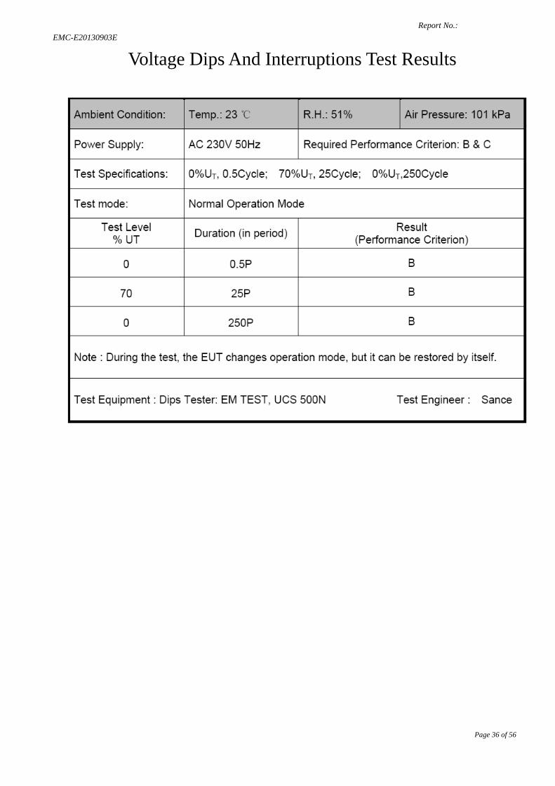
13.7 Test Result PASS. Please refer to the following page.
Report No.: EMC-E20130903E
Page 36 of 56
Voltage Dips And Interruptions Test Results
Report No.: EMC-E20130903E
Page 37 of 56
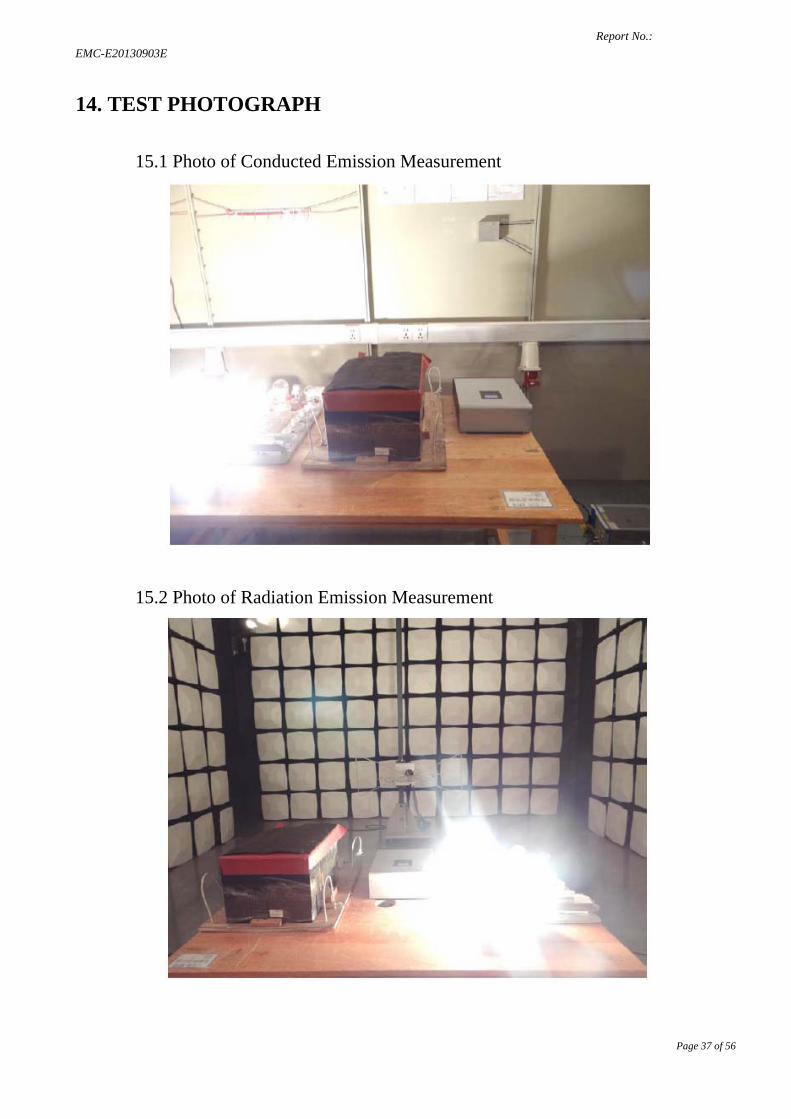
14. TEST PHOTOGRAPH
15.1 Photo of Conducted Emission Measurement
15.2 Photo of Radiation Emission Measurement
Report No.: EMC-E20130903E
Page 38 of 56
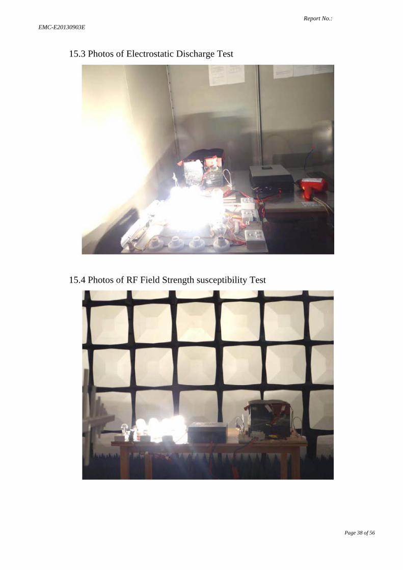
15.3 Photos of Electrostatic Discharge Test
15.4 Photos of RF Field Strength susceptibility Test
Report No.: EMC-E20130903E
Page 39 of 56
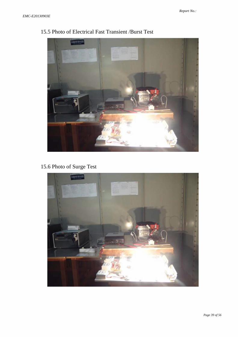
15.5 Photo of Electrical Fast Transient /Burst Test
15.6 Photo of Surge Test
Report No.: EMC-E20130903E
Page 40 of 56
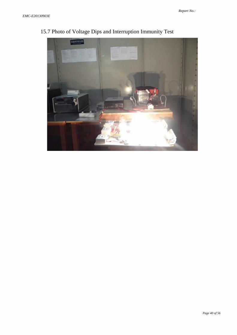
15.7 Photo of Voltage Dips and Interruption Immunity Test
Report No.: EMC-E20130903E
Page 41 of 56
APPENDIX I
Report No.: EMC-E20130903E
Page 42 of 56
Report No.: EMC-E20130903E
Page 43 of 56
Report No.: EMC-E20130903E
Page 44 of 56
Report No.: EMC-E20130903E
Page 45 of 56
APPENDIX II
Report No.: EMC-E20130903E
Page 46 of 56
Report No.: EMC-E20130903E
Page 47 of 56
Report No.: EMC-E20130903E
Page 48 of 56
APPENDIX Ⅲ
Report No.: EMC-E20130903E
Page 49 of 56
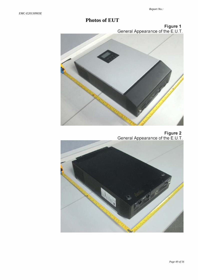
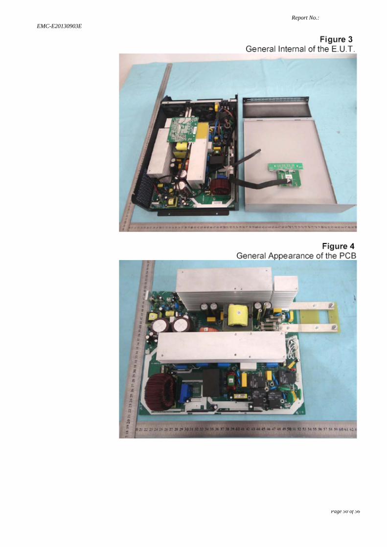
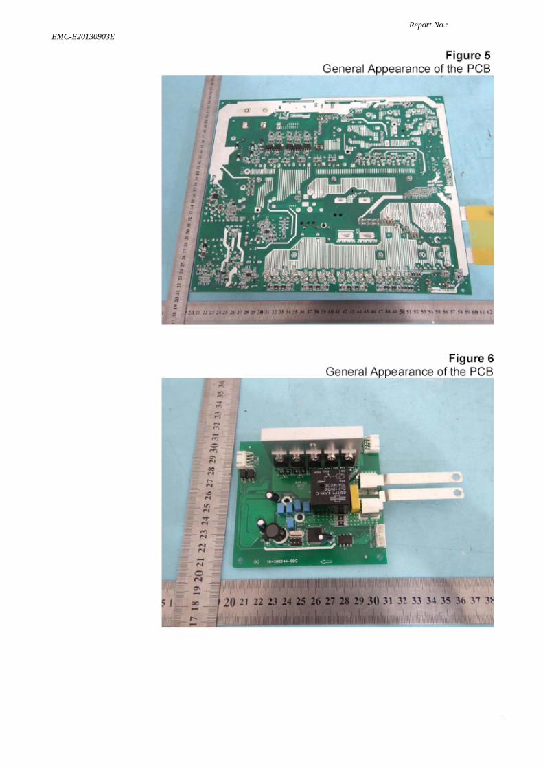
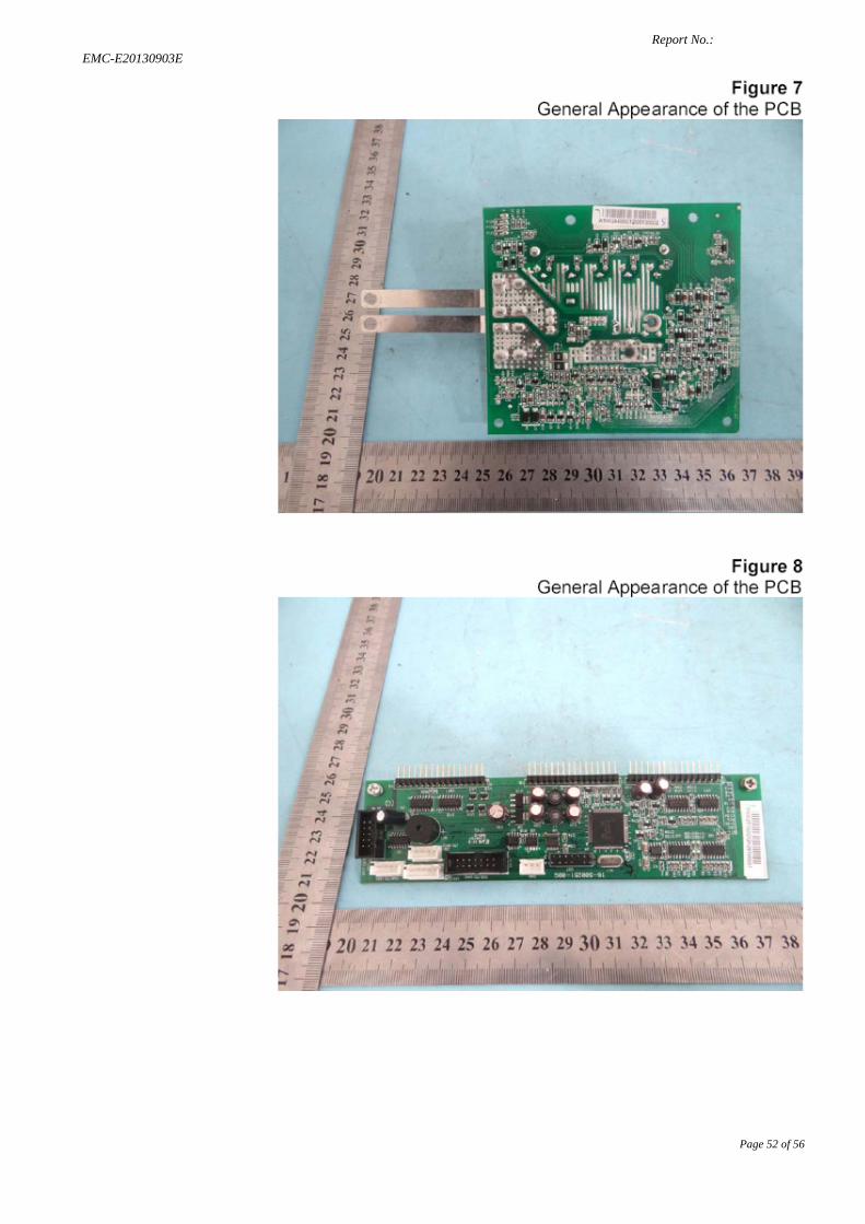
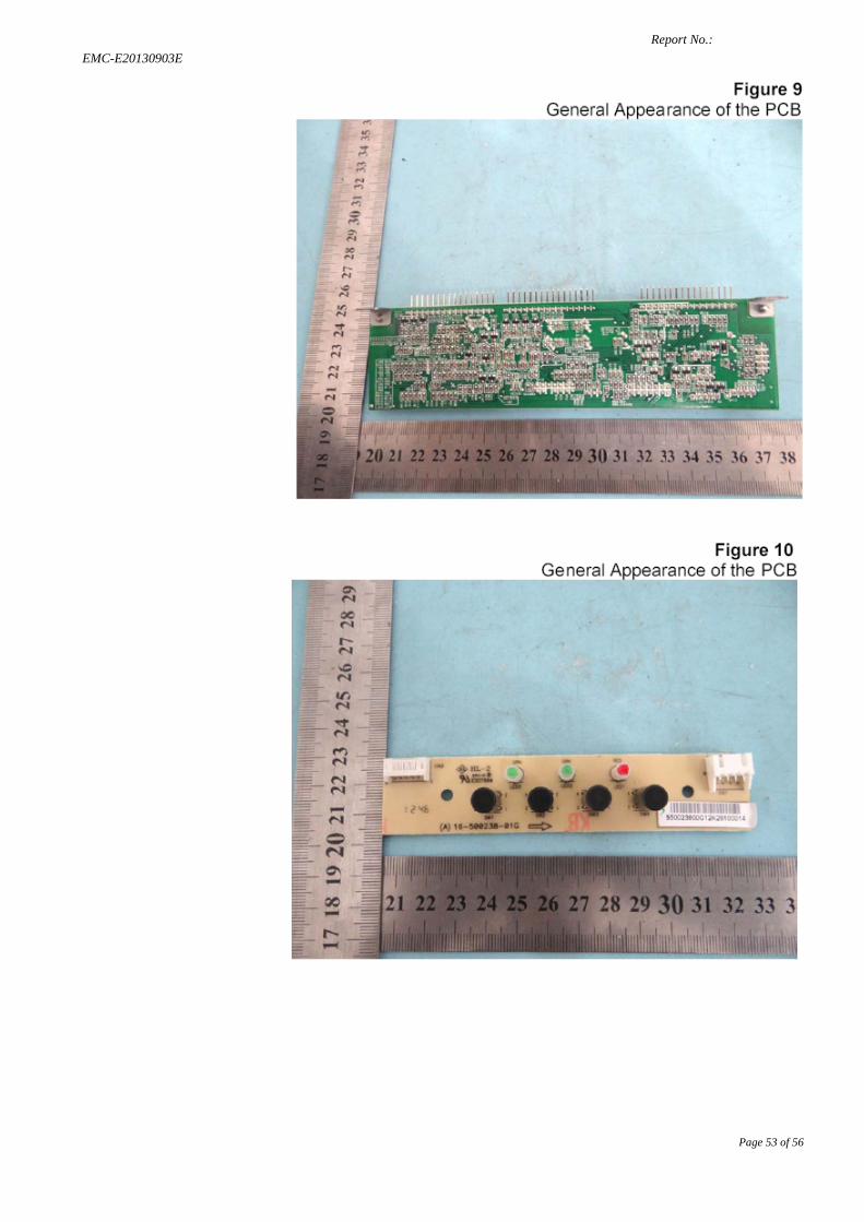
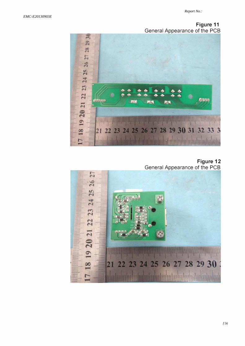
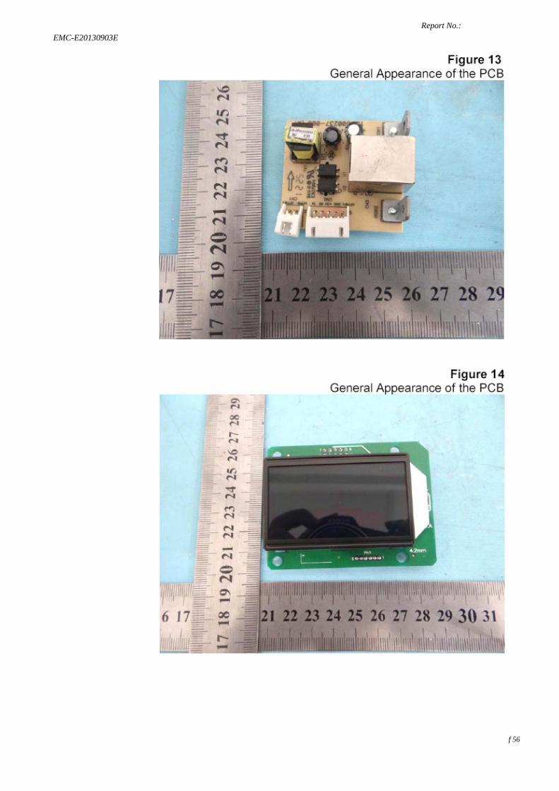
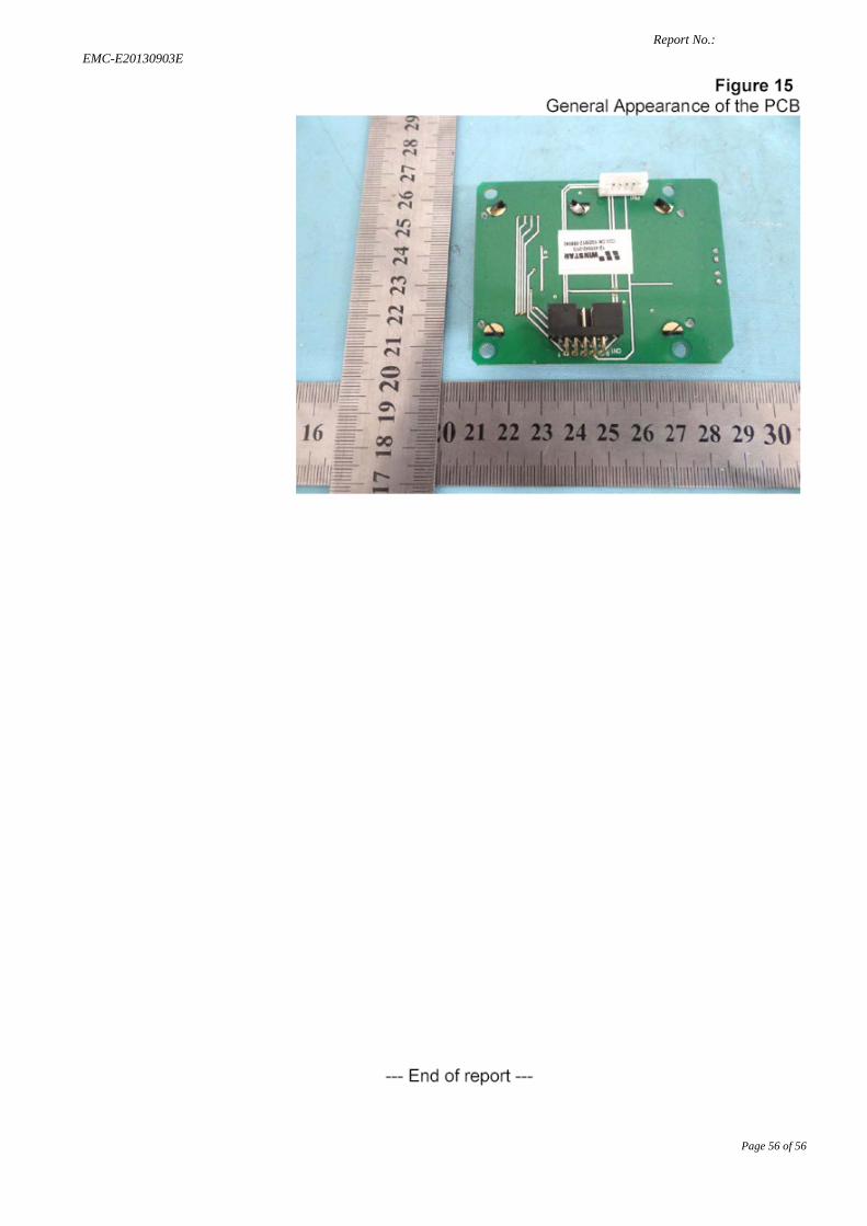
Photos of EUT
Report No.: EMC-E20130903E
Page 50 of 56
Report No.: EMC-E20130903E
Page 51 of 56
Report No.: EMC-E20130903E
Page 52 of 56
Report No.: EMC-E20130903E
Page 53 of 56
Report No.: EMC-E20130903E
Page 54 of 56
Report No.: EMC-E20130903E
Page 55 of 56
Report No.: EMC-E20130903E
Page 56 of 56
Recommended