Electrical-Thermal Co-Simulation in Understanding Interconnect Global Warming
Electrical-Thermal Co-Simulationin Understanding Interconnect Global Warming
Tianjian LuUniversity of Illinois at Urbana-Champaign
April 7, 2014
Electrical-Thermal Co-Simulation in Understanding Interconnect Global Warming
Interconnect Warming
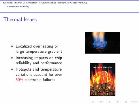
Thermal Issues
I Localized overheating orlarge temperature gradient
I Increasing impacts on chipreliability and performance
I Hotspots and temperaturevariations account for over50% electronic failures
Electrical-Thermal Co-Simulation in Understanding Interconnect Global Warming
Interconnect Warming
The Mutual Influences
Interconnect Scaling ExacerbatesThermal Issues
I Interconnects dominatepower dissipation.
I Interconnect scaling andlower supply voltage lead tohigh power and currentdensity.
I Interconnects (3-D) bringdifficulties in heat removal.
Thermal Impacts on InterconnectReliability and Deisgn
I Joule heating under normalworking condition
I Electromigration underlarge-current stress
I Distortions on signaltransmission
I Large-temperature gradient
Electrical-Thermal Co-Simulation in Understanding Interconnect Global Warming
Interconnect Scaling on Thermal Issues
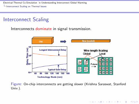
Interconnect Scaling
Interconnects dominate in signal transmission.
Figure: On-chip interconnects are getting slower (Krishna Saraswat, StanfordUniv.).
Electrical-Thermal Co-Simulation in Understanding Interconnect Global Warming
Interconnect Scaling on Thermal Issues
Interconnect Scaling
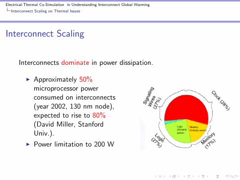
Interconnects dominate in power dissipation.
I Approximately 50%microprocessor powerconsumed on interconnects(year 2002, 130 nm node),expected to rise to 80%(David Miller, StanfordUniv.).
I Power limitation to 200 W
Electrical-Thermal Co-Simulation in Understanding Interconnect Global Warming
Interconnect Scaling on Thermal Issues
Interconnect Scaling
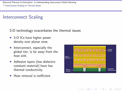
3-D technology exacerbates the thermal issues
I 3-D ICs have higher powerdensity over planar ones.
I Interconnect, especially theglobal tier, is far away from theheat sink.
I Adhesive layers (low dielectricconstant material) have lowthermal conductivity.
I Heat removal is inefficient.
Electrical-Thermal Co-Simulation in Understanding Interconnect Global Warming
Interconnect Scaling on Thermal Issues
Interconnect Scaling
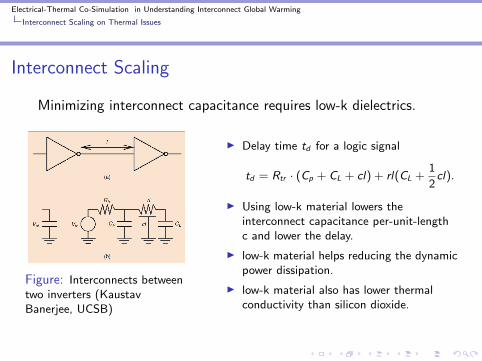
Minimizing interconnect capacitance requires low-k dielectrics.
Figure: Interconnects betweentwo inverters (KaustavBanerjee, UCSB)
I Delay time td for a logic signal
td = Rtr · (Cp + CL + cl) + rl(CL +1
2cl).
I Using low-k material lowers theinterconnect capacitance per-unit-lengthc and lower the delay.
I low-k material helps reducing the dynamicpower dissipation.
I low-k material also has lower thermalconductivity than silicon dioxide.
Electrical-Thermal Co-Simulation in Understanding Interconnect Global Warming
Thermal Impacts on Interconnect Design and Reliability
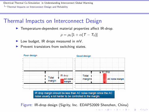
Thermal Impacts on Interconnect DesignI Temperature-dependent material properties affect IR-drop.
ρ = ρ0 [1 + α(T − T0)]
I Low budget, IR drops measured in mV.
I Prevent transistors from switching states.
Figure: IR-drop design (Sigrity, Inc. EDAPS2009 Shenzhen, China)
Electrical-Thermal Co-Simulation in Understanding Interconnect Global Warming
Thermal Impacts on Interconnect Design and Reliability
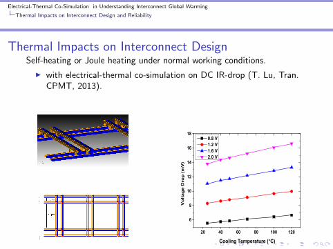
Thermal Impacts on Interconnect DesignSelf-heating or Joule heating under normal working conditions.
I with electrical-thermal co-simulation on DC IR-drop (T. Lu, Tran.CPMT, 2013).
20 40 60 80 100 120
6
8
10
12
14
16
18
Vo
ltag
e D
rop
(m
V)
Cooling Temperature ( C)
0.8 V 1.2 V 1.6 V 2.0 V
Electrical-Thermal Co-Simulation in Understanding Interconnect Global Warming
Thermal Impacts on Interconnect Design and Reliability
Thermal Impacts on Interconnect Reliability
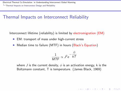
Interconnect lifetime (reliability) is limited by electromigration (EM)
I EM: transport of mass under high-current stress
I Median time to failure (MTF) in hours (Black’s Equation)
1
MTF∝ J2e
− φ
kT
where J is the current density, φ is an activation energy, k is theBoltzmann constant, T is temperature. (James Black, 1969)
Electrical-Thermal Co-Simulation in Understanding Interconnect Global Warming
Thermal Impacts on Interconnect Design and Reliability
Thermal Impacts on Interconnect Reliability
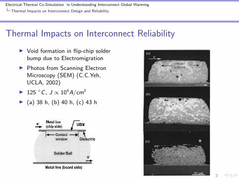
I Void formation in flip-chip solderbump due to Electromigration
I Photos from Scanning ElectronMicroscopy (SEM) (C.C.Yeh,UCLA, 2002)
I 125 C , J ∝ 104A/cm2
I (a) 38 h, (b) 40 h, (c) 43 h
Electrical-Thermal Co-Simulation in Understanding Interconnect Global Warming
Thermal Impacts on Interconnect Design and Reliability
Thermal Impacts on Interconnect Reliability
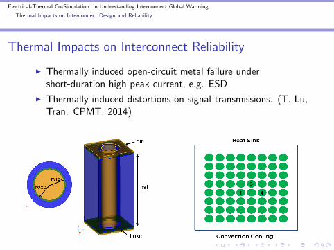
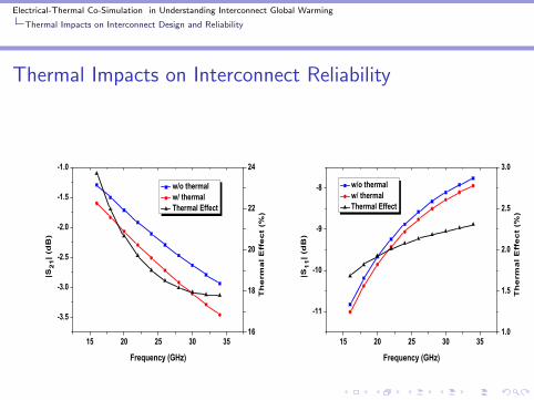
I Thermally induced open-circuit metal failure undershort-duration high peak current, e.g. ESD
I Thermally induced distortions on signal transmissions. (T. Lu,Tran. CPMT, 2014)
Electrical-Thermal Co-Simulation in Understanding Interconnect Global Warming
Thermal Impacts on Interconnect Design and Reliability
Thermal Impacts on Interconnect Reliability
15 20 25 30 35
-3.5
-3.0
-2.5
-2.0
-1.5
-1.0
w/o thermal w/ thermal Thermal Effect
Frequency (GHz)
|S2
1|
(dB
)
16
18
20
22
24
Th
erm
al
Eff
ec
t (%
)
15 20 25 30 35
-11
-10
-9
-8 w/o thermal w/ thermal Thermal Effect
Frequency (GHz)
|S1
1|
(dB
)
1.0
1.5
2.0
2.5
3.0
Th
erm
al
Eff
ec
t (%
)

Electrical-Thermal Co-Simulation in Understanding Interconnect Global Warming
Electrical-Thermal Co-Simulation
Electrical-Thermal Co-Simulation
I To address all the aforementioned issues simultaneously
I Accurate prediction of the electrical-thermal behaviors
Power Dissipation
Pc =
∫v
σ|E |2dV
Pd = ωε0
∫v
ε′′r |E |2dV
Temperature-dependent materialproperty
ρ = ρ0 [1 + α(T − T0)]
µp(T ) = µp0
(T
300
)− 32
Electrical-Thermal Co-Simulation in Understanding Interconnect Global Warming
Electrical-Thermal Co-Simulation
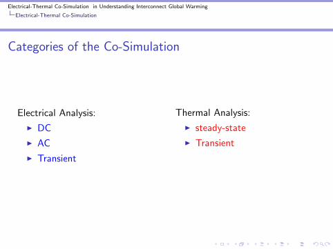
Categories of the Co-Simulation
Electrical Analysis:
I DC
I AC
I Transient
Thermal Analysis:
I steady-state
I Transient

Electrical-Thermal Co-Simulation in Understanding Interconnect Global Warming
Electrical-Thermal Co-Simulation
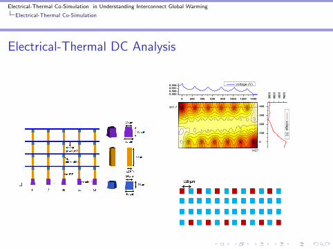
Electrical-Thermal DC Analysis
Electrical Analysis:
∇ · σ∇φ = 0
φ = φc on Γvc
σ∂φ
∂n=
φ
RSon Γload
Thermal Analysis:
∇ · k∇T = −P
T = Tc on Γtc
k∂T
∂n= −h(T − Ta) on Γconv
Electrical-Thermal Co-Simulation in Understanding Interconnect Global Warming
Electrical-Thermal Co-Simulation
Electrical-Thermal DC Analysis
0 200 400 600 800 1000 1200 1400
0
100
200
300
400
1427
391.7
0.5850.5880.5910.594
voltage (V)
0.5850.5880.5910.594
voltage (V)
Electrical-Thermal Co-Simulation in Understanding Interconnect Global Warming
Electrical-Thermal Co-Simulation
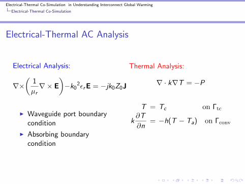
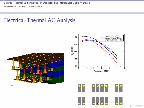
Electrical-Thermal AC Analysis
Electrical Analysis:
∇×(
1
µr∇× E
)−k0
2εrE = −jk0Z0J
I Waveguide port boundarycondition
I Absorbing boundarycondition
Thermal Analysis:
∇ · k∇T = −P
T = Tc on Γtc
k∂T
∂n= −h(T − Ta) on Γconv
Electrical-Thermal Co-Simulation in Understanding Interconnect Global Warming
Electrical-Thermal Co-Simulation
Electrical-Thermal AC Analysis
0 1 2 3 4 5 6-2.0
-1.5
-1.0
-0.5
0.0
|S21
| (dB
)Frequency (GHz)
copper, silicon 1 S/m copper, silicon 10 S/m tungsten, silicon 10 S/m
Electrical-Thermal Co-Simulation in Understanding Interconnect Global Warming
Electrical-Thermal Co-Simulation
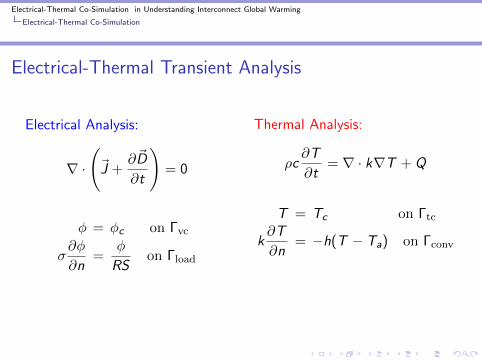
Electrical-Thermal Transient Analysis
Electrical Analysis:
∇ ·
(~J +
∂~D
∂t
)= 0
φ = φc on Γvc
σ∂φ
∂n=
φ
RSon Γload
Thermal Analysis:
ρc∂T
∂t= ∇ · k∇T + Q
T = Tc on Γtc
k∂T
∂n= −h(T − Ta) on Γconv
Electrical-Thermal Co-Simulation in Understanding Interconnect Global Warming
Electrical-Thermal Co-Simulation
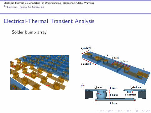
Electrical-Thermal Transient Analysis
Solder bump array
Electrical-Thermal Co-Simulation in Understanding Interconnect Global Warming
Electrical-Thermal Co-Simulation
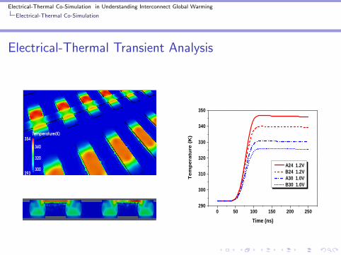
Electrical-Thermal Transient Analysis
0 5 0 1 0 0 1 5 0 2 0 0 2 5 02 9 0
3 0 0
3 1 0
3 2 0
3 3 0
3 4 0
3 5 0
Tem
pera
ture
(K)
T i m e ( n s )
A 2 4 1 . 2 V B 2 4 1 . 2 V A 3 0 1 . 0 V B 3 0 1 . 0 V
Electrical-Thermal Co-Simulation in Understanding Interconnect Global Warming
Electrical-Thermal Co-Simulation
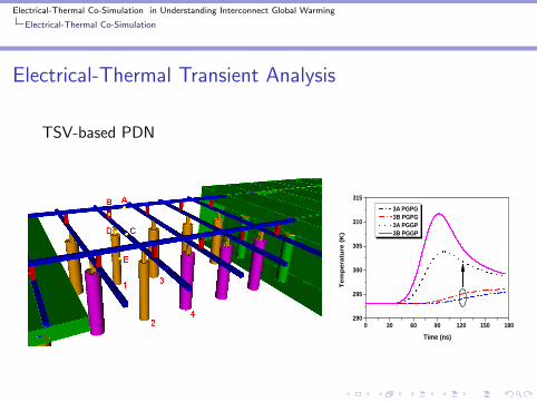
Electrical-Thermal Transient Analysis
TSV-based PDN
0 3 0 6 0 9 0 1 2 0 1 5 0 1 8 02 9 0
2 9 5
3 0 0
3 0 5
3 1 0
3 1 5
Temp
eratu
re (K
)T i m e ( n s )
3 A P G P G 3 B P G P G 3 A P G G P 3 B P G G P
Electrical-Thermal Co-Simulation in Understanding Interconnect Global Warming
Electrical-Thermal Co-Simulation
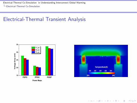
Electrical-Thermal Transient Analysis
PGPG PPGG PGGP15
20
25
30
35
Vo
ltag
e D
rop
(m
V)
Power Maps
11 m 12 m 13 m
Electrical-Thermal Co-Simulation in Understanding Interconnect Global Warming
Fast and Efficient Solver for Large-Scale Problems
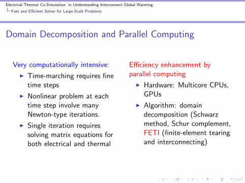
Domain Decomposition and Parallel Computing
Very computationally intensive:
I Time-marching requires finetime steps
I Nonlinear problem at eachtime step involve manyNewton-type iterations.
I Single iteration requiressolving matrix equations forboth electrical and thermal
Efficiency enhancement byparallel computing
I Hardware: Multicore CPUs,GPUs
I Algorithm: domaindecomposition (Schwarzmethod, Schur complement,FETI (finite-element tearingand interconnecting)
Electrical-Thermal Co-Simulation in Understanding Interconnect Global Warming
Fast and Efficient Solver for Large-Scale Problems
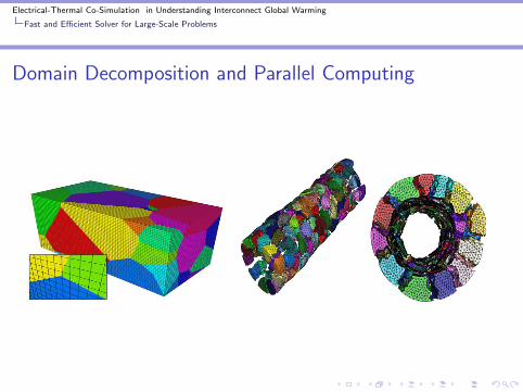
Domain Decomposition and Parallel Computing
Electrical-Thermal Co-Simulation in Understanding Interconnect Global Warming
Fast and Efficient Solver for Large-Scale Problems
Finite Element Tearing and Interconnecting
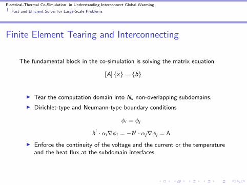
The fundamental block in the co-simulation is solving the matrix equation
[A] x = b
I Tear the computation domain into Ns non-overlapping subdomains.
I Dirichlet-type and Neumann-type boundary conditions
φi = φj
ni · αi∇φi = −nj · αj∇φj = Λ
I Enforce the continuity of the voltage and the current or the temperatureand the heat flux at the subdomain interfaces.
Electrical-Thermal Co-Simulation in Understanding Interconnect Global Warming
Fast and Efficient Solver for Large-Scale Problems
Finite Element Tearing and Interconnecting
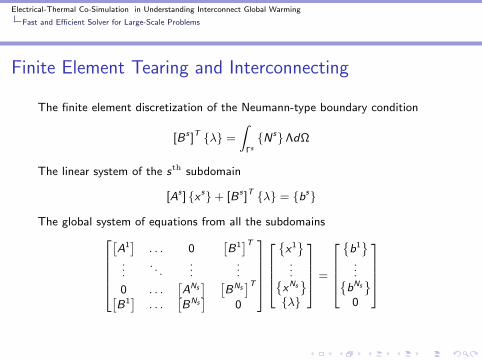
The finite element discretization of the Neumann-type boundary condition
[B s ]T λ =
∫ΓsNsΛdΩ
The linear system of the sth subdomain
[As ] x s+ [B s ]T λ = bs
The global system of equations from all the subdomains[A1]
. . . 0[B1]T
.... . .
......
0 . . .[ANs] [
BNs]T[
B1]
. . .[BNs
]0
x1
...xNs
λ
=
b1
...bNs
0
Electrical-Thermal Co-Simulation in Understanding Interconnect Global Warming
Fast and Efficient Solver for Large-Scale Problems
Finite Element Tearing and Interconnecting
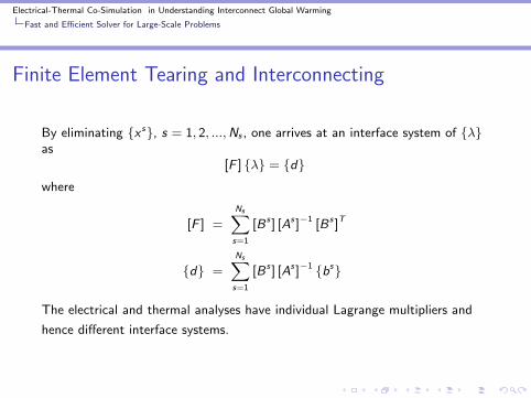
By eliminating x s, s = 1, 2, ...,Ns , one arrives at an interface system of λas
[F ] λ = dwhere
[F ] =
Ns∑s=1
[B s ] [As ]−1 [B s ]T
d =
Ns∑s=1
[B s ] [As ]−1 bs
The electrical and thermal analyses have individual Lagrange multipliers and
hence different interface systems.
Electrical-Thermal Co-Simulation in Understanding Interconnect Global Warming
Fast and Efficient Solver for Large-Scale Problems
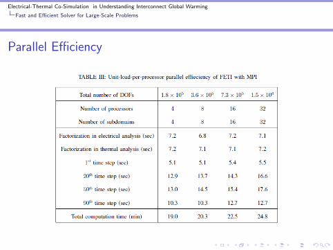
Parallel Efficiency
Recommended