Dynamic Analysis and loads definition for the structural design of the Euclid spacecraft
M.Bellini1, A.Calvi
2
1Thales Alenia Space Italy,
Strada Antica di Collegno 253, I-10143 Torino, Italy
e-mail: [email protected]
2 European Space Agency, ESTEC
Keplerlaan 1, 2200 AG Noordwijk, The Netherlands
Abstract Euclid is an ESA astronomy and astrophysics space mission. The mission aims at understanding why the
expansion of the Universe is accelerating and what is the nature of the source responsible for this
acceleration which physicists refer to as dark energy. Euclid spacecraft launch date is planned in 2020. It
will be launched by a Soyuz launcher from ESA’s spaceport in Kourou and then travel to the L2 Sun-
Earth Lagrangian point for a 6 years mission.
The launch phase generally generates the highest mechanical loads for the spacecraft structures. Predicting
appropriate loads is one of the most challenging aspects of spacecraft design. Calculating accurate
responses is important not only to assess the structure ability to survive but also to provide design and test
environments and requirements for units and subsystems.
Starting from the mechanical environment induced by the launch vehicle, as defined in the Soyuz User’s
Manual, the paper provides a short overview of the logic and criteria applied to define a complete set of
loads and mechanical environments both for design and test verification of the Euclid spacecraft,
including subsystems, instruments and units. Dynamic analyses, mainly frequency response, random
vibration and vibro-acoustic response analyses, have been performed to accomplish the complex and
difficult task.
In particular this paper addresses the effort made in order to avoid the potential overdesign of the
spacecraft secondary structure. For this purpose specific structural analyses under vibro-acoustic and base-
drive random vibration environments have been performed and some novel aspects are pointed out.
Finally the paper depicts the basic strategy put in place to avoid the overdesign (and at later stages also the
overtesting) of the Euclid scientific instruments.
1 Introduction
The Euclid satellite will be launched by Soyuz. In despite of the uncertainties, related to the preliminary
phase of the project, and a finite element mathematical model not yet representative of all the design and
project solutions, a significant effort has been made to define appropriate loads to design correctly the
structure and to define the requirements for units and subsystems limiting the risk of overdesign and
overtesting the Euclid scientific instruments.
809
2 Euclid Project
2.1 The mission
Euclid is an ESA medium class astronomy and astrophysics space mission. The mission aims at
understanding why the expansion of the Universe is accelerating and what is the nature of the source
responsible for this acceleration which physicists refer to as dark energy. Euclid will explore how the
Universe evolved over the past 10 billion years to address questions related to fundamental physics and
cosmology on the nature and properties of dark energy, dark matter and gravity, as well as on the physics
of the early universe and the initial conditions which seed the formation of cosmic structure. To
accomplish the Euclid mission, ESA has selected Thales Alenia Space Italy (TASI) as Prime Contractor
for the implementation phase (i.e. design, development, manufacturing, integration and testing) of the
spacecraft and its Service Module, Airbus Defence and Space (ex-Astrium France) for the Payload
Module and the “Euclid Consortium” as the single team having the scientific responsibility of the mission
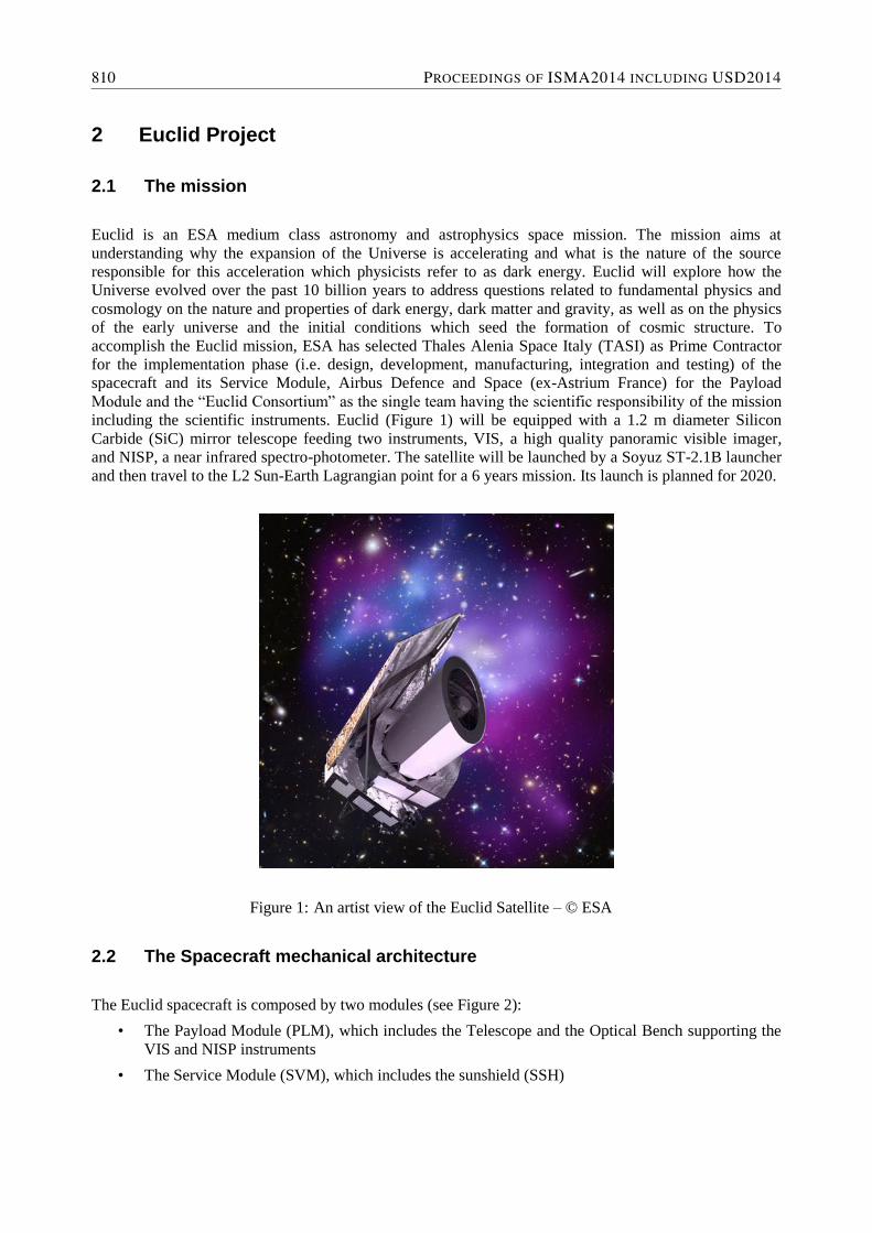
including the scientific instruments. Euclid (Figure 1) will be equipped with a 1.2 m diameter Silicon
Carbide (SiC) mirror telescope feeding two instruments, VIS, a high quality panoramic visible imager,
and NISP, a near infrared spectro-photometer. The satellite will be launched by a Soyuz ST-2.1B launcher
and then travel to the L2 Sun-Earth Lagrangian point for a 6 years mission. Its launch is planned for 2020.
Figure 1: An artist view of the Euclid Satellite – © ESA
2.2 The Spacecraft mechanical architecture
The Euclid spacecraft is composed by two modules (see Figure 2):
• The Payload Module (PLM), which includes the Telescope and the Optical Bench supporting the
VIS and NISP instruments
• The Service Module (SVM), which includes the sunshield (SSH)
810 PROCEEDINGS OF ISMA2014 INCLUDING USD2014
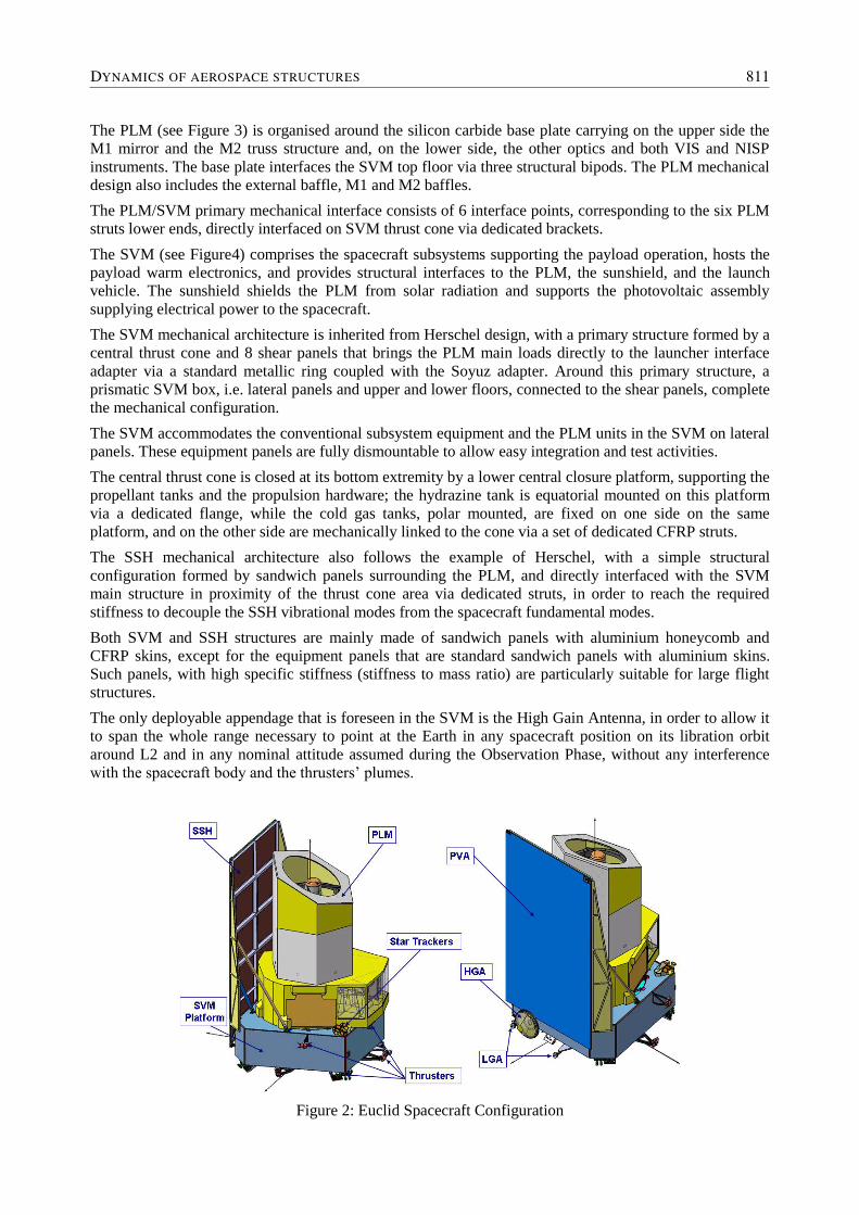
The PLM (see Figure 3) is organised around the silicon carbide base plate carrying on the upper side the
M1 mirror and the M2 truss structure and, on the lower side, the other optics and both VIS and NISP
instruments. The base plate interfaces the SVM top floor via three structural bipods. The PLM mechanical
design also includes the external baffle, M1 and M2 baffles.
The PLM/SVM primary mechanical interface consists of 6 interface points, corresponding to the six PLM
struts lower ends, directly interfaced on SVM thrust cone via dedicated brackets.
The SVM (see Figure4) comprises the spacecraft subsystems supporting the payload operation, hosts the
payload warm electronics, and provides structural interfaces to the PLM, the sunshield, and the launch
vehicle. The sunshield shields the PLM from solar radiation and supports the photovoltaic assembly
supplying electrical power to the spacecraft.
The SVM mechanical architecture is inherited from Herschel design, with a primary structure formed by a
central thrust cone and 8 shear panels that brings the PLM main loads directly to the launcher interface
adapter via a standard metallic ring coupled with the Soyuz adapter. Around this primary structure, a
prismatic SVM box, i.e. lateral panels and upper and lower floors, connected to the shear panels, complete
the mechanical configuration.
The SVM accommodates the conventional subsystem equipment and the PLM units in the SVM on lateral
panels. These equipment panels are fully dismountable to allow easy integration and test activities.
The central thrust cone is closed at its bottom extremity by a lower central closure platform, supporting the
propellant tanks and the propulsion hardware; the hydrazine tank is equatorial mounted on this platform
via a dedicated flange, while the cold gas tanks, polar mounted, are fixed on one side on the same
platform, and on the other side are mechanically linked to the cone via a set of dedicated CFRP struts.
The SSH mechanical architecture also follows the example of Herschel, with a simple structural
configuration formed by sandwich panels surrounding the PLM, and directly interfaced with the SVM
main structure in proximity of the thrust cone area via dedicated struts, in order to reach the required
stiffness to decouple the SSH vibrational modes from the spacecraft fundamental modes.
Both SVM and SSH structures are mainly made of sandwich panels with aluminium honeycomb and
CFRP skins, except for the equipment panels that are standard sandwich panels with aluminium skins.
Such panels, with high specific stiffness (stiffness to mass ratio) are particularly suitable for large flight
structures.
The only deployable appendage that is foreseen in the SVM is the High Gain Antenna, in order to allow it
to span the whole range necessary to point at the Earth in any spacecraft position on its libration orbit
around L2 and in any nominal attitude assumed during the Observation Phase, without any interference
with the spacecraft body and the thrusters’ plumes.
Figure 2: Euclid Spacecraft Configuration
DYNAMICS OF AEROSPACE STRUCTURES 811
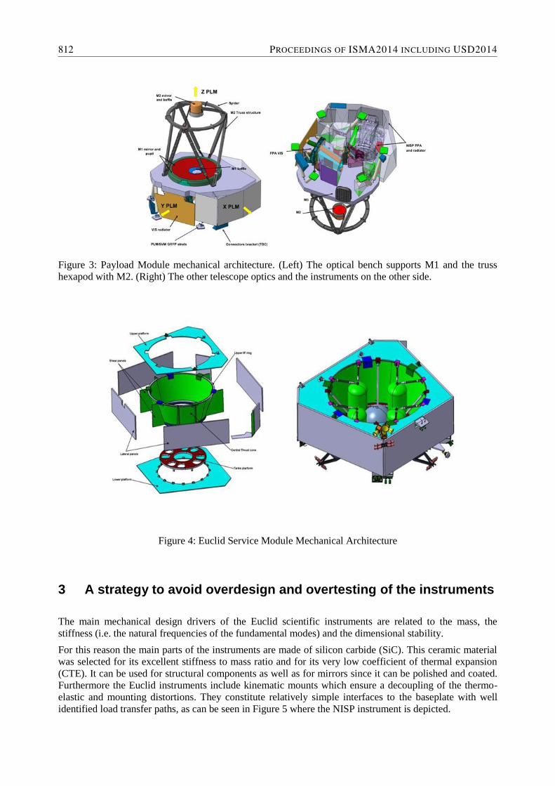
Figure 3: Payload Module mechanical architecture. (Left) The optical bench supports M1 and the truss
hexapod with M2. (Right) The other telescope optics and the instruments on the other side.
Figure 4: Euclid Service Module Mechanical Architecture
3 A strategy to avoid overdesign and overtesting of the instruments
The main mechanical design drivers of the Euclid scientific instruments are related to the mass, the
stiffness (i.e. the natural frequencies of the fundamental modes) and the dimensional stability.
For this reason the main parts of the instruments are made of silicon carbide (SiC). This ceramic material
was selected for its excellent stiffness to mass ratio and for its very low coefficient of thermal expansion
(CTE). It can be used for structural components as well as for mirrors since it can be polished and coated.
Furthermore the Euclid instruments include kinematic mounts which ensure a decoupling of the thermo-
elastic and mounting distortions. They constitute relatively simple interfaces to the baseplate with well
identified load transfer paths, as can be seen in Figure 5 where the NISP instrument is depicted.
812 PROCEEDINGS OF ISMA2014 INCLUDING USD2014
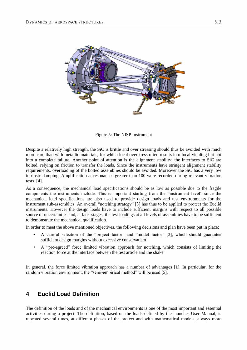
Figure 5: The NISP Instrument
Despite a relatively high strength, the SiC is brittle and over stressing should thus be avoided with much
more care than with metallic materials, for which local overstress often results into local yielding but not
into a complete failure. Another point of attention is the alignment stability: the interfaces to SiC are
bolted, relying on friction to transfer the loads. Since the instruments have stringent alignment stability
requirements, overloading of the bolted assemblies should be avoided. Moreover the SiC has a very low
intrinsic damping. Amplification at resonances greater than 100 were recorded during relevant vibration
tests [4].
As a consequence, the mechanical load specifications should be as low as possible due to the fragile
components the instruments include. This is important starting from the “instrument level” since the
mechanical load specifications are also used to provide design loads and test environments for the
instrument sub-assemblies. An overall “notching strategy” [3] has thus to be applied to protect the Euclid
instruments. However the design loads have to include sufficient margins with respect to all possible
source of uncertainties and, at later stages, the test loadings at all levels of assemblies have to be sufficient
to demonstrate the mechanical qualification.
In order to meet the above mentioned objectives, the following decisions and plan have been put in place:
• A careful selection of the “project factor” and “model factor” [2], which should guarantee
sufficient design margins without excessive conservatism
• A “pre-agreed” force limited vibration approach for notching, which consists of limiting the
reaction force at the interface between the test article and the shaker
In general, the force limited vibration approach has a number of advantages [1]. In particular, for the
random vibration environment, the “semi-empirical method” will be used [5].
4 Euclid Load Definition
The definition of the loads and of the mechanical environments is one of the most important and essential
activities during a project. The definition, based on the loads defined by the launcher User Manual, is
repeated several times, at different phases of the project and with mathematical models, always more
DYNAMICS OF AEROSPACE STRUCTURES 813
accurate. But the first loads and mechanical environments are very important and, for Euclid they have
been defined by TASI with the first Euclid model available, result of the integration of Airbus PLM model
and TASI spacecraft finite element model.
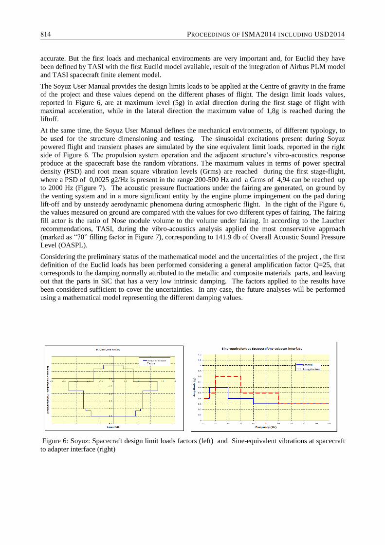
The Soyuz User Manual provides the design limits loads to be applied at the Centre of gravity in the frame
of the project and these values depend on the different phases of flight. The design limit loads values,
reported in Figure 6, are at maximum level (5g) in axial direction during the first stage of flight with
maximal acceleration, while in the lateral direction the maximum value of 1,8g is reached during the
liftoff.
At the same time, the Soyuz User Manual defines the mechanical environments, of different typology, to
be used for the structure dimensioning and testing. The sinusoidal excitations present during Soyuz
powered flight and transient phases are simulated by the sine equivalent limit loads, reported in the right
side of Figure 6. The propulsion system operation and the adjacent structure’s vibro-acoustics response
produce at the spacecraft base the random vibrations. The maximum values in terms of power spectral
density (PSD) and root mean square vibration levels (Grms) are reached during the first stage-flight,
where a PSD of 0,0025 g2/Hz is present in the range 200-500 Hz and a Grms of 4,94 can be reached up
to 2000 Hz (Figure 7). The acoustic pressure fluctuations under the fairing are generated, on ground by
the venting system and in a more significant entity by the engine plume impingement on the pad during
lift-off and by unsteady aerodynamic phenomena during atmospheric flight. In the right of the Figure 6,
the values measured on ground are compared with the values for two different types of fairing. The fairing
fill actor is the ratio of Nose module volume to the volume under fairing. In according to the Laucher
recommendations, TASI, during the vibro-acoustics analysis applied the most conservative approach
(marked as “70” filling factor in Figure 7), corresponding to 141.9 db of Overall Acoustic Sound Pressure
Level (OASPL).
Considering the preliminary status of the mathematical model and the uncertainties of the project , the first
definition of the Euclid loads has been performed considering a general amplification factor Q=25, that
corresponds to the damping normally attributed to the metallic and composite materials parts, and leaving
out that the parts in SiC that has a very low intrinsic damping. The factors applied to the results have
been considered sufficient to cover the uncertainties. In any case, the future analyses will be performed
using a mathematical model representing the different damping values.
Figure 6: Soyuz: Spacecraft design limit loads factors (left) and Sine-equivalent vibrations at spacecraft
to adapter interface (right)
814 PROCEEDINGS OF ISMA2014 INCLUDING USD2014
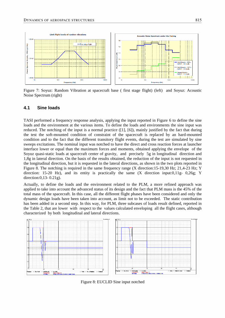
Figure 7: Soyuz: Random Vibration at spacecraft base ( first stage flight) (left) and Soyuz: Acoustic
Noise Spectrum (right)
4.1 Sine loads
TASI performed a frequency response analysis, applying the input reported in Figure 6 to define the sine
loads and the environment at the various items. To define the loads and environments the sine input was
reduced. The notching of the input is a normal practice ([1], [6]), mainly justified by the fact that during
the test the soft-mounted condition of constraint of the spacecraft is replaced by an hard-mounted
condition and to the fact that the different transitory flight events, during the test are simulated by sine
sweeps excitations. The nominal input was notched to have the direct and cross reaction forces at launcher
interface lower or equal than the maximum forces and moments, obtained applying the envelope of the
Soyuz quasi-static loads at spacecraft center of gravity, and precisely 5g in longitudinal direction and
1,8g in lateral direction. On the basis of the results obtained, the reduction of the input is not requested in
the longitudinal direction, but it is requested in the lateral directions, as shown in the two plots reported in
Figure 8. The notching is required in the same frequency range (X direction:15-19,30 Hz; 21,4-23 Hz; Y
direction: 15-20 Hz), and its entity is practically the same (X direction input:0,11g- 0,26g; Y
direction:0,13- 0.21g).
Actually, to define the loads and the environment related to the PLM, a more refined approach was
applied to take into account the advanced status of its design and the fact that PLM mass is the 45% of the
total mass of the spacecraft. In this case, all the different flight phases have been considered and only the
dynamic design loads have been taken into account, as limit not to be exceeded. The static contribution
has been added in a second step. In this way, for PLM, three subcases of loads result defined, reported in
the Table 2, that are lower with respect to the values calculated enveloping all the flight cases, although
characterized by both longitudinal and lateral directions.
Figure 8: EUCLID Sine input notched
DYNAMICS OF AEROSPACE STRUCTURES 815
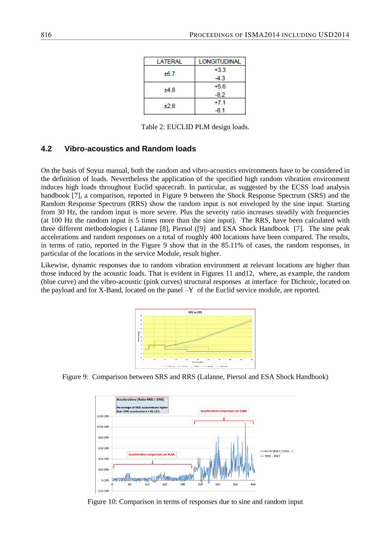
Table 2: EUCLID PLM design loads.
4.2 Vibro-acoustics and Random loads
On the basis of Soyuz manual, both the random and vibro-acoustics environments have to be considered in
the definition of loads. Nevertheless the application of the specified high random vibration environment
induces high loads throughout Euclid spacecraft. In particular, as suggested by the ECSS load analysis
handbook [7], a comparison, reported in Figure 9 between the Shock Response Spectrum (SRS) and the
Random Response Spectrum (RRS) show the random input is not enveloped by the sine input. Starting
from 30 Hz, the random input is more severe. Plus the severity ratio increases steadily with frequencies
(at 100 Hz the random input is 5 times more than the sine input). The RRS, have been calculated with
three different methodologies ( Lalanne [8], Piersol ([9] and ESA Shock Handbook [7]. The sine peak
accelerations and random responses on a total of roughly 400 locations have been compared. The results,
in terms of ratio, reported in the Figure 9 show that in the 85.11% of cases, the random responses, in
particular of the locations in the service Module, result higher.
Likewise, dynamic responses due to random vibration environment at relevant locations are higher than
those induced by the acoustic loads. That is evident in Figures 11 and12, where, as example, the random
(blue curve) and the vibro-acoustic (pink curves) structural responses at interface for Dichroic, located on
the payload and for X-Band, located on the panel –Y of the Euclid service module, are reported.
Figure 9: Comparison between SRS and RRS (Lalanne, Piersol and ESA Shock Handbook)
Figure 10: Comparison in terms of responses due to sine and random input
816 PROCEEDINGS OF ISMA2014 INCLUDING USD2014
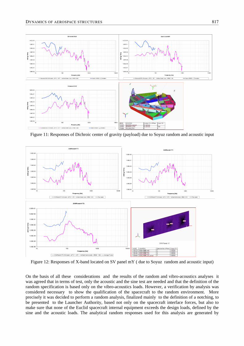
Figure 11: Responses of Dichroic center of gravity (payload) due to Soyuz random and acoustic input
Figure 12: Responses of X-band located on SV panel mY ( due to Soyuz random and acoustic input)
On the basis of all these considerations and the results of the random and vibro-acoustics analyses it
was agreed that in terms of test, only the acoustic and the sine test are needed and that the definition of the
random specification is based only on the vibro-acoustics loads. However, a verification by analysis was
considered necessary to show the qualification of the spacecraft to the random environment. More
precisely it was decided to perform a random analysis, finalized mainly to the definition of a notching, to
be presented to the Launcher Authority, based not only on the spacecraft interface forces, but also to
make sure that none of the Euclid spacecraft internal equipment exceeds the design loads, defined by the
sine and the acoustic loads. The analytical random responses used for this analysis are generated by
DYNAMICS OF AEROSPACE STRUCTURES 817
multiaxial, i.e. simultaneous, application of the Soyuz random input along the three excitation axes. As a
consequence, the proposed notched input is “universal”, meaning not axis specific. At the preliminary
stage of the program this is acceptable, because the analysis reported is meant to be an initial assessment
of the actual notching. In addition, this analysis is produced considering a conservative modal damping
(Q=25 all over the frequency range) and because actual notching will be defined starting from test
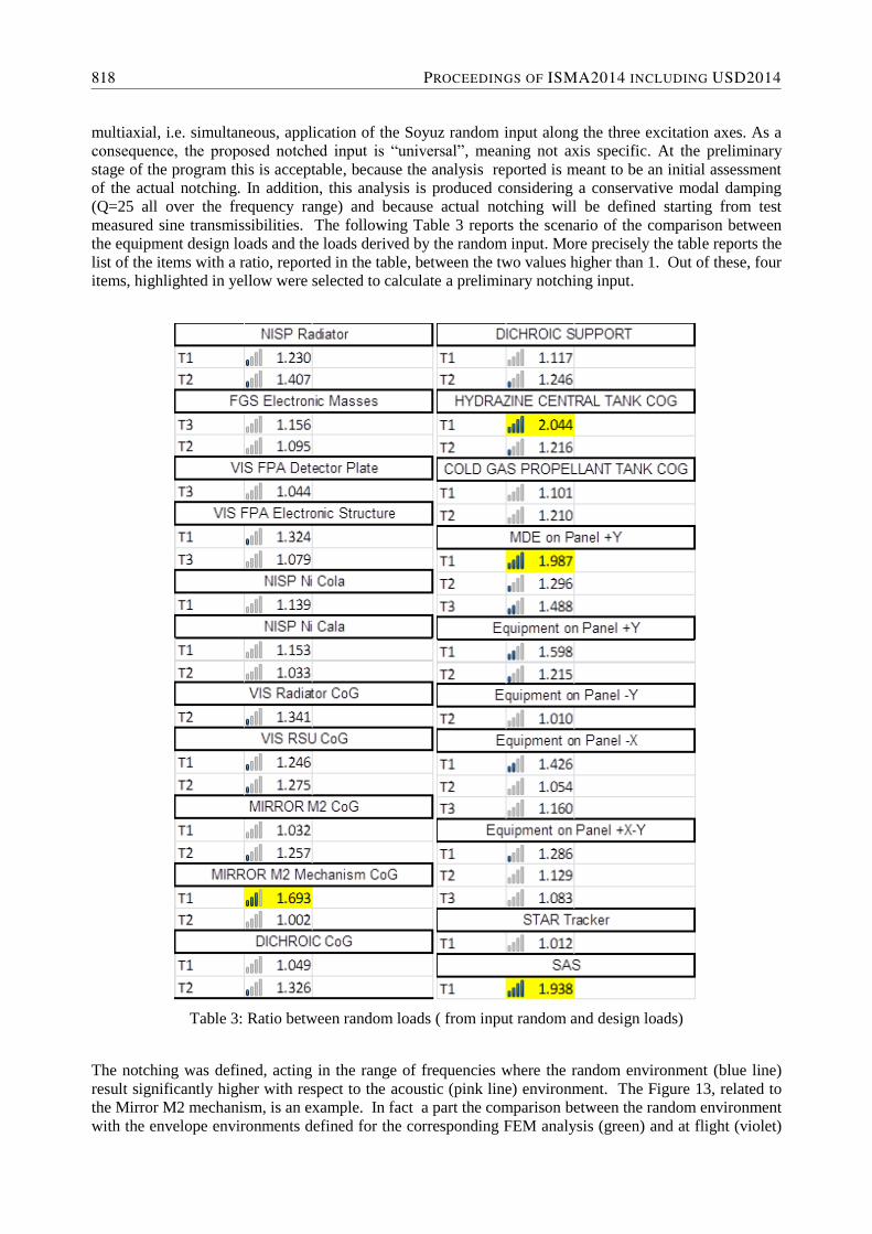
measured sine transmissibilities. The following Table 3 reports the scenario of the comparison between
the equipment design loads and the loads derived by the random input. More precisely the table reports the
list of the items with a ratio, reported in the table, between the two values higher than 1. Out of these, four
items, highlighted in yellow were selected to calculate a preliminary notching input.
Table 3: Ratio between random loads ( from input random and design loads)
The notching was defined, acting in the range of frequencies where the random environment (blue line)
result significantly higher with respect to the acoustic (pink line) environment. The Figure 13, related to
the Mirror M2 mechanism, is an example. In fact a part the comparison between the random environment
with the envelope environments defined for the corresponding FEM analysis (green) and at flight (violet)
818 PROCEEDINGS OF ISMA2014 INCLUDING USD2014
and qualification (light blue) levels, the figure shows, as well, the frequencies ranges, starting point to
define the notching profiles.
Figure 13: Mirror M2 Mechanism random and acoustic environment and first preliminary definition of
notching pockets.
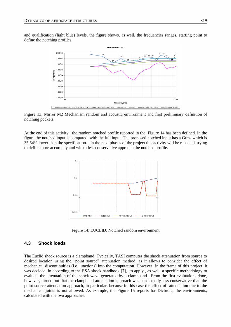
At the end of this activity, the random notched profile reported in the Figure 14 has been defined. In the
figure the notched input is compared with the full input. The proposed notched input has a Grms which is
35,54% lower than the specification. In the next phases of the project this activity will be repeated, trying
to define more accurately and with a less conservative approach the notched profile.
Figure 14: EUCLID: Notched random environment
4.3 Shock loads
The Euclid shock source is a clampband. Typically, TASI computes the shock attenuation from source to
desired location using the “point source” attenuation method, as it allows to consider the effect of
mechanical discontinuities (i.e. junctions) into the computation. However in the frame of this project, it
was decided, in according to the ESA shock handbook [7], to apply , as well, a specific methodology to
evaluate the attenuation of the shock wave generated by a clampband . From the first evaluations done,
however, turned out that the clampband attenuation approach was consistently less conservative than the
point source attenuation approach, in particular, because in this case the effect of attenuation due to the
mechanical joints is not allowed. As example, the Figure 15 reports for Dichroic, the environments,
calculated with the two approaches.
DYNAMICS OF AEROSPACE STRUCTURES 819
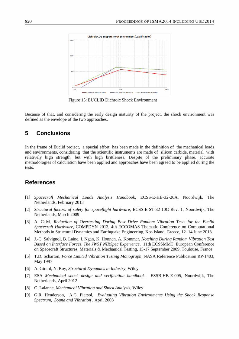
Figure 15: EUCLID Dichroic Shock Environment
Because of that, and considering the early design maturity of the project, the shock environment was
defined as the envelope of the two approaches.
5 Conclusions
In the frame of Euclid project, a special effort has been made in the definition of the mechanical loads
and environments, considering that the scientific instruments are made of silicon carbide, material with
relatively high strength, but with high brittleness. Despite of the preliminary phase, accurate
methodologies of calculation have been applied and approaches have been agreed to be applied during the
tests.
References
[1] Spacecraft Mechanical Loads Analysis Handbook, ECSS-E-HB-32-26A, Noordwijk, The
Netherlands, February 2013
[2] Structural factors of safety for spaceflight hardware, ECSS-E-ST-32-10C Rev. 1, Noordwijk, The
Netherlands, March 2009
[3] A. Calvi, Reduction of Overtesting During Base-Drive Random Vibration Tests for the Euclid
Spacecraft Hardware, COMPDYN 2013, 4th ECCOMAS Thematic Conference on Computational
Methods in Structural Dynamics and Earthquake Engineering, Kos Island, Greece, 12–14 June 2013
[4] J.-C. Salvignol, B. Laine, I. Ngan, K. Honnen, A. Kommer, Notching During Random Vibration Test
Based on Interface Forces. The JWST NIRSpec Experience. 11th ECSSMMT, European Conference
on Spacecraft Structures, Materials & Mechanical Testing, 15-17 September 2009, Toulouse, France
[5] T.D. Scharton, Force Limited Vibration Testing Monograph, NASA Reference Publication RP-1403,
May 1997
[6] A. Girard, N. Roy, Structural Dynamics in Industry, Wiley
[7] ESA Mechanical shock design and verification handbook, ESSB-HB-E-005, Noordwijk, The
Netherlands, April 2012
[8] C. Lalanne, Mechanical Vibration and Shock Analysis, Wiley
[9] G.R. Henderson, A.G. Piersol, Evaluating Vibration Environments Using the Shock Response
Spectrum, Sound and Vibration , April 2003
820 PROCEEDINGS OF ISMA2014 INCLUDING USD2014
Recommended