Embed Size (px)
Citation preview
PDF generated on 19 Sep 2016DISCLAIMER : UNCONTROLLED WHEN PRINTED – PLEASE CHECK THE STATUS OF THE DOCUMENT IN IDM
Technical Specifications (In-Cash Procurement)
Computational Fluid Dynamics Analysis for loads definition during accidental scenarios
The purpose of this document is to specify the requirements for the provision of engineering support of Computational Fluid Dynamics (CFD) analysis in order to define the thermal loads during accidental scenarios.
IDM UID
TF35GSVERSION CREATED ON / VERSION / STATUS
15 Sep 2016 / 1.4 / Approved
EXTERNAL REFERENCE / VERSION
Page 1 of 16
Table of Contents
1 PURPOSE............................................................................................................................22 SCOPE .................................................................................................................................23 DEFINITIONS ....................................................................................................................24 REFERENCES....................................................................................................................35 ESTIMATED DURATION................................................................................................36 WORK DESCRIPTION.....................................................................................................3
6.1 Technical background ....................................................................................................36.2 Scope of the work...........................................................................................................86.3 Task 1 description ........................................................................................................11
6.3.1 Subtask 1: Models generation and validation in normal operating conditions .....116.3.2 Subtask 2: Transient models definition and associated results .............................126.3.3 Subtask 3: Sensitivity analyses .............................................................................126.3.4 Subtask 4: Additional events (optional)................................................................13
7 RESPONSIBILITIES .......................................................................................................137.1 Contractor’s responsibilities.........................................................................................137.2 IO responsibility ...........................................................................................................13
8 LIST OF DELIVERABLES AND DUE DATES ...........................................................139 ACCEPTANCE CRITERIA............................................................................................1410 SPECIFIC REQUIREMENTS AND CONDITIONS....................................................1411 WORK MONITORING / MEETING SCHEDULE .....................................................1512 BREAKDOWN .................................................................................................................1513 QUALITY ASSURANCE (QA) REQUIREMENTS.....................................................1514 SAFETY REQUIREMENTS...........................................................................................15
Page 2 of 16
1 PurposeThe purpose of this document is to specify the requirements for the provision of engineering support in the area of fluid dynamics, and particularly CFD analysis in order to define the thermal loads during accidental scenarios.
2 ScopeThe contractor will work on the following subjects as required following priorities defined by the line manager:
- Perform thermal-hydraulics and CFD activities required by IO,- Provide a set of documents that reports the analyses performed and fulfil the needs from
IO,- Verify CFD analyses performed by the IO or by external companies and control
consistency with the ITER specifications and requirements,- Review the documents prepared by IO (analysis documents, guidelines, etc.).
The CFD activity is mainly oriented to the development and use of models in order to define the thermal and hydraulics behaviour inside the tokamak building during nominal operating conditions and accidental conditions, including fire events.
3 Definitions3D Three-dimensionalAS Analysis Section/DivisionBOS Baking Operation StateCAD Computer Aided DesignCFD Computational Fluid DynamicsCr CryostatCSR Cryostat Space RoomDA Domestic AgencyHiG Helium Ingress in the GalleryHTC Heat Transfer CoefficientICE Ingress of Coolant EventIO ITER OrganizationKoM Kick-off MeetingLOCA Loss Of Coolant AccidentLOVA Loss Of Vacuum AccidentMS Magnet SystemPC Port CellPIC Protection Important ComponentQA Quality AssuranceRO Responsible OfficerTBD To Be DefinedTRO Task Responsible OfficerTS Thermal ShieldsUDF User Defined Function
Page 3 of 16
VV Vacuum Vessel
For a complete list of ITER abbreviations see [9].
4 References[1] Accident Analysis Report (AAR) Volume I - Event Identification and Selection
ITER document 2DPVGT[2] Accident Analysis Report (AAR) Volume II - Reference Event Analysis
ITER document 2DJFX3[3] Load Specifications (LS)
ITER document 222QGL[4] Cryostat wall behaviour under water and He ingress
ITER document 35CF69[5] MELCOR analysis of Cr ICEs, Cr LOVAs and HiG events
ITER document PG3RXG[6] Order dated 7 February 2012 relating to the general technical regulations applicable to
INB – ENITER document 7M2YKF
[7] ITER Procurement Quality RequirementsITER document 22MFG4
[8] MQP Standard TOC For Analysis ReportsITER document 22F4A3
[9] ITER AbbreviationsITER document 2MU6W5
[10] Generic requirements for the competences and qualifications of external intervenersITER document SBT3UA
[11] Provisions for implementation of the Generic Safety requirements by the external intervenersITER document SBSTBM
[12] Procurement Requirements for Producing a Quality PlanITER document 22MFMW
[13] Quality Assurance for ITER Safety CodesITER document 258LKL
[14] Thermal Analysis of Cryostat Space RoomITER document S4PNTM
5 Estimated DurationThe duration for the contract shall be 36 months (including options) from the contract signature date.
6 Work Description
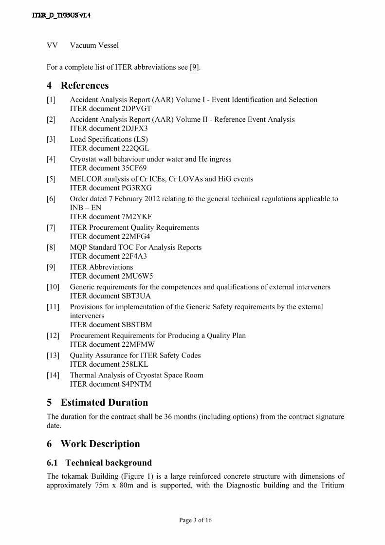
6.1 Technical backgroundThe tokamak Building (Figure 1) is a large reinforced concrete structure with dimensions of approximately 75m x 80m and is supported, with the Diagnostic building and the Tritium
Page 4 of 16
Building, by a rectangular basement (Figure 2 and Figure 3) which provide the seismic isolation by Anti-Seismic Bearing (ASB) placed on top of pillars.
Figure 1 Isometric view of Tokamak Building
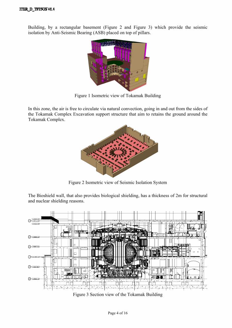
In this zone, the air is free to circulate via natural convection, going in and out from the sides of the Tokamak Complex Excavation support structure that aim to retains the ground around the Tokamak Complex.
Figure 2 Isometric view of Seismic Isolation System
The Bioshield wall, that also provides biological shielding, has a thickness of 2m for structural and nuclear shielding reasons.
Figure 3 Section view of the Tokamak Building
Page 5 of 16
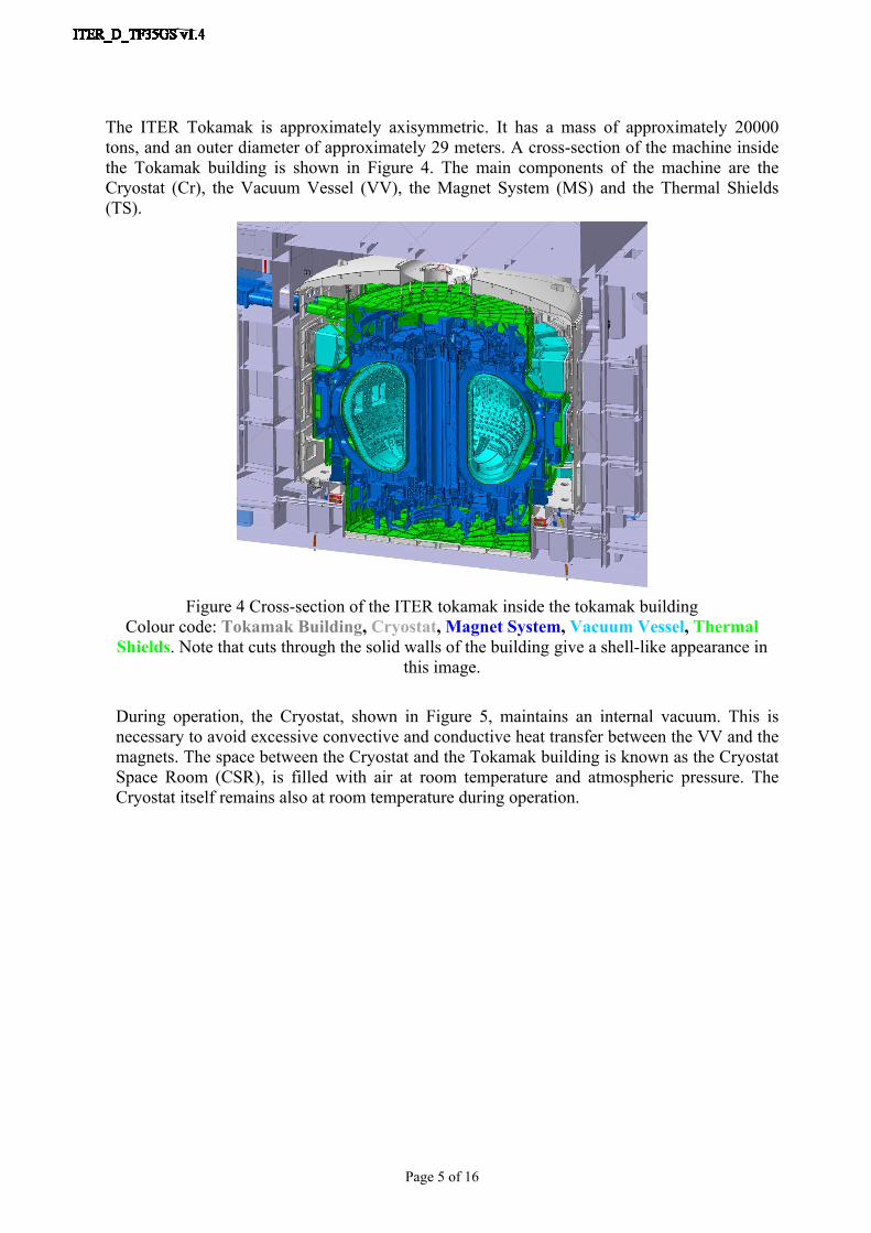
The ITER Tokamak is approximately axisymmetric. It has a mass of approximately 20000 tons, and an outer diameter of approximately 29 meters. A cross-section of the machine inside the Tokamak building is shown in Figure 4. The main components of the machine are the Cryostat (Cr), the Vacuum Vessel (VV), the Magnet System (MS) and the Thermal Shields (TS).
Figure 4 Cross-section of the ITER tokamak inside the tokamak buildingColour code: Tokamak Building, Cryostat, Magnet System, Vacuum Vessel, Thermal
Shields. Note that cuts through the solid walls of the building give a shell-like appearance in this image.
During operation, the Cryostat, shown in Figure 5, maintains an internal vacuum. This is necessary to avoid excessive convective and conductive heat transfer between the VV and the magnets. The space between the Cryostat and the Tokamak building is known as the Cryostat Space Room (CSR), is filled with air at room temperature and atmospheric pressure. The Cryostat itself remains also at room temperature during operation.
Page 6 of 16
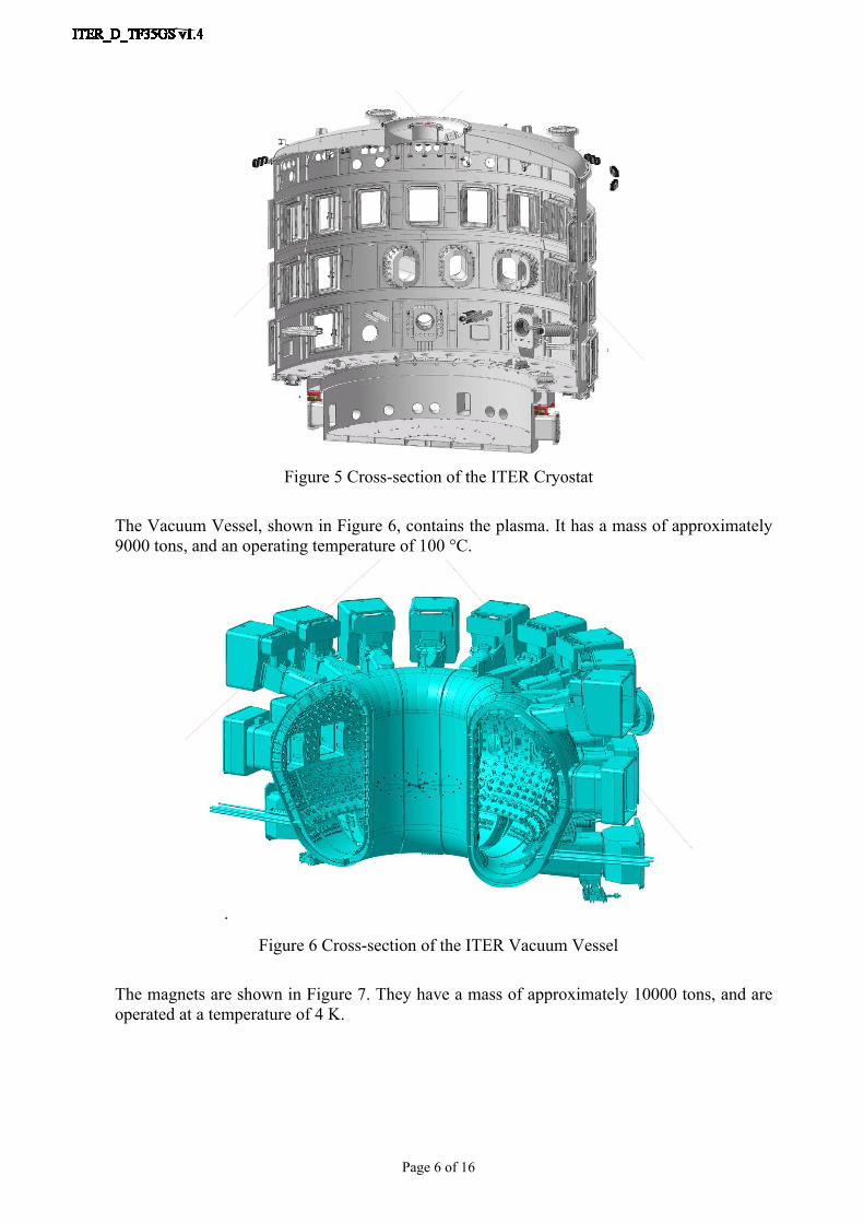
Figure 5 Cross-section of the ITER Cryostat
The Vacuum Vessel, shown in Figure 6, contains the plasma. It has a mass of approximately 9000 tons, and an operating temperature of 100 °C.
Figure 6 Cross-section of the ITER Vacuum Vessel
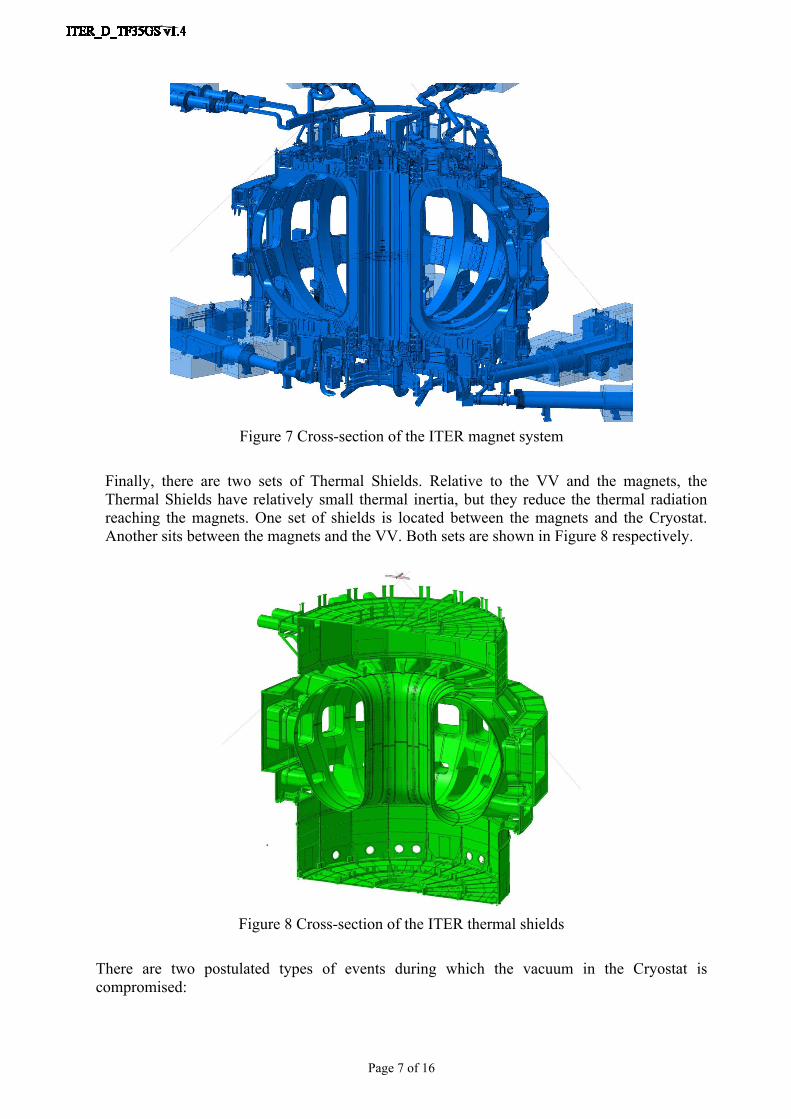
The magnets are shown in Figure 7. They have a mass of approximately 10000 tons, and are operated at a temperature of 4 K.
Page 7 of 16
Figure 7 Cross-section of the ITER magnet system
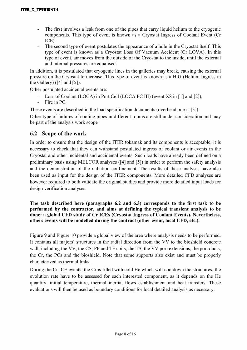
Finally, there are two sets of Thermal Shields. Relative to the VV and the magnets, the Thermal Shields have relatively small thermal inertia, but they reduce the thermal radiation reaching the magnets. One set of shields is located between the magnets and the Cryostat. Another sits between the magnets and the VV. Both sets are shown in Figure 8 respectively.
Figure 8 Cross-section of the ITER thermal shields
There are two postulated types of events during which the vacuum in the Cryostat is compromised:
Page 8 of 16
- The first involves a leak from one of the pipes that carry liquid helium to the cryogenic components. This type of event is known as a Cryostat Ingress of Coolant Event (Cr ICE).
- The second type of event postulates the appearance of a hole in the Cryostat itself. This type of event is known as a Cryostat Loss Of Vacuum Accident (Cr LOVA). In this type of event, air moves from the outside of the Cryostat to the inside, until the external and internal pressures are equalised.
In addition, it is postulated that cryogenic lines in the galleries may break, causing the external pressure on the Cryostat to increase. This type of event is known as a HiG (Helium Ingress in the Gallery) ([4] and [5]). Other postulated accidental events are:
- Loss of Coolant (LOCA) in Port Cell (LOCA PC III) (event X8 in [1] and [2]),- Fire in PC.
These events are described in the load specification documents (overhead one is [3]).Other type of failures of cooling pipes in different rooms are still under consideration and may be part of the analysis work scope
6.2 Scope of the workIn order to ensure that the design of the ITER tokamak and its components is acceptable, it is necessary to check that they can withstand postulated ingress of coolant or air events in the Cryostat and other incidental and accidental events. Such loads have already been defined on a preliminary basis using MELCOR analyses ([4] and [5]) in order to perform the safety analysis and the demonstration of the radiation confinement. The results of these analyses have also been used as input for the design of the ITER components. More detailed CFD analyses are however required to both validate the original studies and provide more detailed input loads for design verification analyses.
The task described here (paragraphs 6.2 and 6.3) corresponds to the first task to be performed by the contractor, and aims at defining the typical transient analysis to be done: a global CFD study of Cr ICEs (Cryostat Ingress of Coolant Events). Nevertheless, others events will be modelled during the contract (other event, local CFD, etc.).
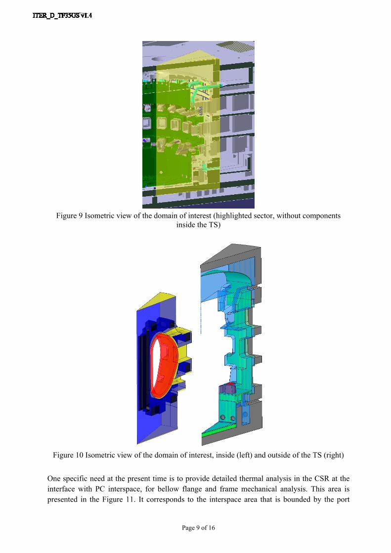
Figure 9 and Figure 10 provide a global view of the area where analysis needs to be performed. It contains all majors’ structures in the radial direction from the VV to the bioshield concrete wall, including the VV, the CS, PF and TF coils, the TS, the VV port extensions, the port ducts, the Cr, the PCs and the bioshield. Note that some supports also exist and must be properly characterized as thermal links.During the Cr ICE events, the Cr is filled with cold He which will cooldown the structures; the evolution rate have to be assessed for each interested component, as it depends on the He quantity, initial temperature, thermal inertia, flows establishment and heat transfers. These evaluations will then be used as boundary conditions for local detailed analysis as necessary.
Page 9 of 16
Figure 9 Isometric view of the domain of interest (highlighted sector, without components inside the TS)
Figure 10 Isometric view of the domain of interest, inside (left) and outside of the TS (right)
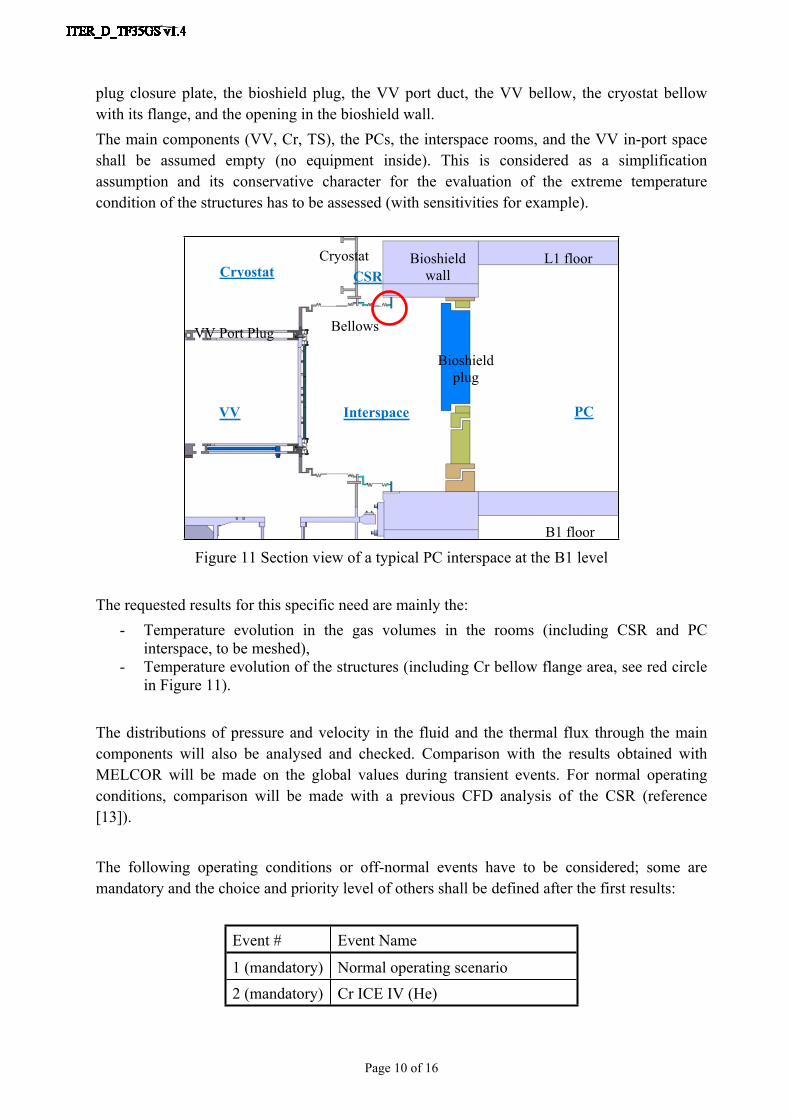
One specific need at the present time is to provide detailed thermal analysis in the CSR at the interface with PC interspace, for bellow flange and frame mechanical analysis. This area is presented in the Figure 11. It corresponds to the interspace area that is bounded by the port
Page 10 of 16
plug closure plate, the bioshield plug, the VV port duct, the VV bellow, the cryostat bellow with its flange, and the opening in the bioshield wall.The main components (VV, Cr, TS), the PCs, the interspace rooms, and the VV in-port space shall be assumed empty (no equipment inside). This is considered as a simplification assumption and its conservative character for the evaluation of the extreme temperature condition of the structures has to be assessed (with sensitivities for example).
Figure 11 Section view of a typical PC interspace at the B1 level
The requested results for this specific need are mainly the:- Temperature evolution in the gas volumes in the rooms (including CSR and PC
interspace, to be meshed),- Temperature evolution of the structures (including Cr bellow flange area, see red circle
in Figure 11).
The distributions of pressure and velocity in the fluid and the thermal flux through the main components will also be analysed and checked. Comparison with the results obtained with MELCOR will be made on the global values during transient events. For normal operating conditions, comparison will be made with a previous CFD analysis of the CSR (reference [13]).
The following operating conditions or off-normal events have to be considered; some are mandatory and the choice and priority level of others shall be defined after the first results:
Event # Event Name
1 (mandatory) Normal operating scenario2 (mandatory) Cr ICE IV (He)
Cryostat
VV Port Plug
B1 floor
PCInterspace
Bioshield plug
Bellows
L1 floorCSR
Bioshield wall
Cryostat
VV
Page 11 of 16
Event # Event Name
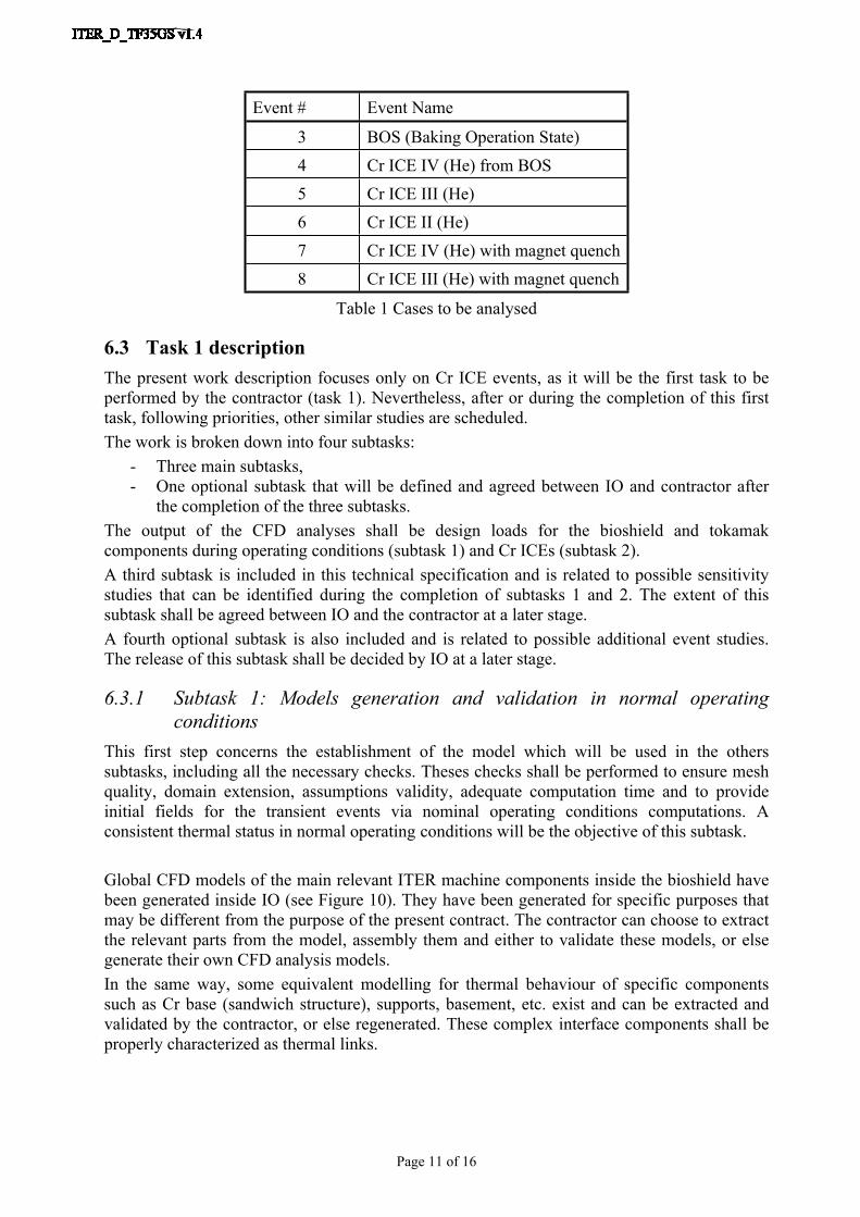
3 BOS (Baking Operation State)4 Cr ICE IV (He) from BOS5 Cr ICE III (He)6 Cr ICE II (He)7 Cr ICE IV (He) with magnet quench8 Cr ICE III (He) with magnet quench
Table 1 Cases to be analysed
6.3 Task 1 descriptionThe present work description focuses only on Cr ICE events, as it will be the first task to be performed by the contractor (task 1). Nevertheless, after or during the completion of this first task, following priorities, other similar studies are scheduled.The work is broken down into four subtasks:
- Three main subtasks,- One optional subtask that will be defined and agreed between IO and contractor after
the completion of the three subtasks.The output of the CFD analyses shall be design loads for the bioshield and tokamak components during operating conditions (subtask 1) and Cr ICEs (subtask 2).A third subtask is included in this technical specification and is related to possible sensitivity studies that can be identified during the completion of subtasks 1 and 2. The extent of this subtask shall be agreed between IO and the contractor at a later stage.A fourth optional subtask is also included and is related to possible additional event studies. The release of this subtask shall be decided by IO at a later stage.
6.3.1 Subtask 1: Models generation and validation in normal operating conditions
This first step concerns the establishment of the model which will be used in the others subtasks, including all the necessary checks. Theses checks shall be performed to ensure mesh quality, domain extension, assumptions validity, adequate computation time and to provide initial fields for the transient events via nominal operating conditions computations. A consistent thermal status in normal operating conditions will be the objective of this subtask.
Global CFD models of the main relevant ITER machine components inside the bioshield have been generated inside IO (see Figure 10). They have been generated for specific purposes that may be different from the purpose of the present contract. The contractor can choose to extract the relevant parts from the model, assembly them and either to validate these models, or else generate their own CFD analysis models.In the same way, some equivalent modelling for thermal behaviour of specific components such as Cr base (sandwich structure), supports, basement, etc. exist and can be extracted and validated by the contractor, or else regenerated. These complex interface components shall be properly characterized as thermal links.
Page 12 of 16
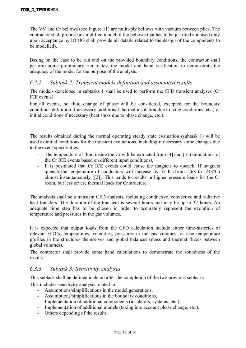
The VV and Cr bellows (see Figure 11) are multi-ply bellows with vacuum between plies. The contractor shall propose a simplified model of the bellows that has to be justified and used only upon acceptance by IO (IO shall provide all details related to the design of the components to be modelled).
Basing on the case to be run and on the provided boundary conditions, the contractor shall perform some preliminary run to test the model and hand verification to demonstrate the adequacy of the model for the purpose of the analysis.
6.3.2 Subtask 2: Transient models definition and associated resultsThe models developed in subtasks 1 shall be used to perform the CFD transient analyses (Cr ICE events).For all events, no fluid change of phase will be considered, excepted for the boundary conditions definition if necessary (additional thermal insulation due to icing conditions, etc.) or initial conditions if necessary (heat sinks due to phase change, etc.).
The results obtained during the normal operating steady state evaluation (subtask 1) will be used as initial conditions for the transient evaluations, including if necessary some changes due to the event specificities:
- The temperature of fluid inside the Cr will be extracted from [4] and [5] (simulations of the Cr ICE events based on different input conditions),
- It is postulated that Cr ICE events could cause the magnets to quench. If magnets quench the temperature of conductors will increase by 55 K (from -268 to -213°C) almost instantaneously ([2]). This tends to results in higher pressure loads for the Cr room, but less severe thermal loads for Cr structure.
The analysis shall be a transient CFD analysis, including conductive, convective and radiative heat transfers. The duration of the transient is several hours and may be up to 32 hours. An adequate time step has to be chosen in order to accurately represent the evolution of temperature and pressures in the gas volumes.
It is expected that output loads from the CFD calculation include either time-histories of relevant HTCs, temperatures, velocities, pressures in the gas volumes, or else temperature profiles in the structures themselves and global balances (mass and thermal fluxes between global volumes). The contractor shall provide some hand calculations to demonstrate the soundness of the results.
6.3.3 Subtask 3: Sensitivity analysesThis subtask shall be defined in detail after the completion of the two previous subtasks.This includes sensitivity analysis related to:
- Assumptions/simplifications in the model generations,- Assumptions/simplifications in the boundary conditions,- Implementation of additional components (insulators, systems, etc.),- Implementation of additional models (taking into account phase change, etc.),- Others depending of the results.
Page 13 of 16
6.3.4 Subtask 4: Additional events (optional)This subtask is optional and its release shall be decided by IO after the completion of the three main subtasks.This includes additional event analysis to perform such as the non-mandatory events defined in Table 1. In these additional events, boundary conditions and/or initial conditions and/or slight scenario changes only differ from main subtask 2.This option may be duplicated as necessary.
7 Responsibilities
7.1 Contractor’s responsibilitiesThe contractor warrants that all personnel supplied under the contract have the necessary qualifications and experience to carry out their work. All short-listed candidates proposed will be interviewed. The work shall be performed on the ITER site because daily exchanges and periodic meetings are foreseen.
7.2 IO responsibilityThe contractor will work under the technical instruction and supervision of the AS manager.ITER will provide the needed information and access to relevant ITER files for executing this work when needed.All issued / requested documents containing this information must be returned to ITER on completion of the contract. IO will provide the licence for the analysis software (ANSYS Fluent) and computing tool (workstation) for the task performed at the ITER work site. For work performed outside the ITER site (if any) the Contractor will provide the software licence and the computing tools.
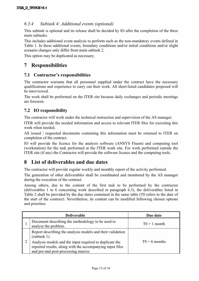
8 List of deliverables and due datesThe contractor will provide regular weekly and monthly report of the activity performed.The generation of other deliverables shall be coordinated and monitored by the AS manager during the execution of the contract.Among others, due to the content of the first task to be performed by the contractor (deliverables 1 to 6 concerning work described in paragraph 6.3), the deliverables listed in Table 2 shall be provided by the due dates contained in the same table (T0 refers to the date of the start of the contract). Nevertheless, its content can be modified following chosen options and priorities.
Deliverable Due date
1 Document describing the methodology to be used to analyse the problem. T0 + 1 month
2
Report describing the analysis models and their validation (subtask 1).Analysis models and the input required to duplicate the reported results, along with the accompanying input files and pre-and post-processing macros
T0 + 6 months
Page 14 of 16
Deliverable Due date
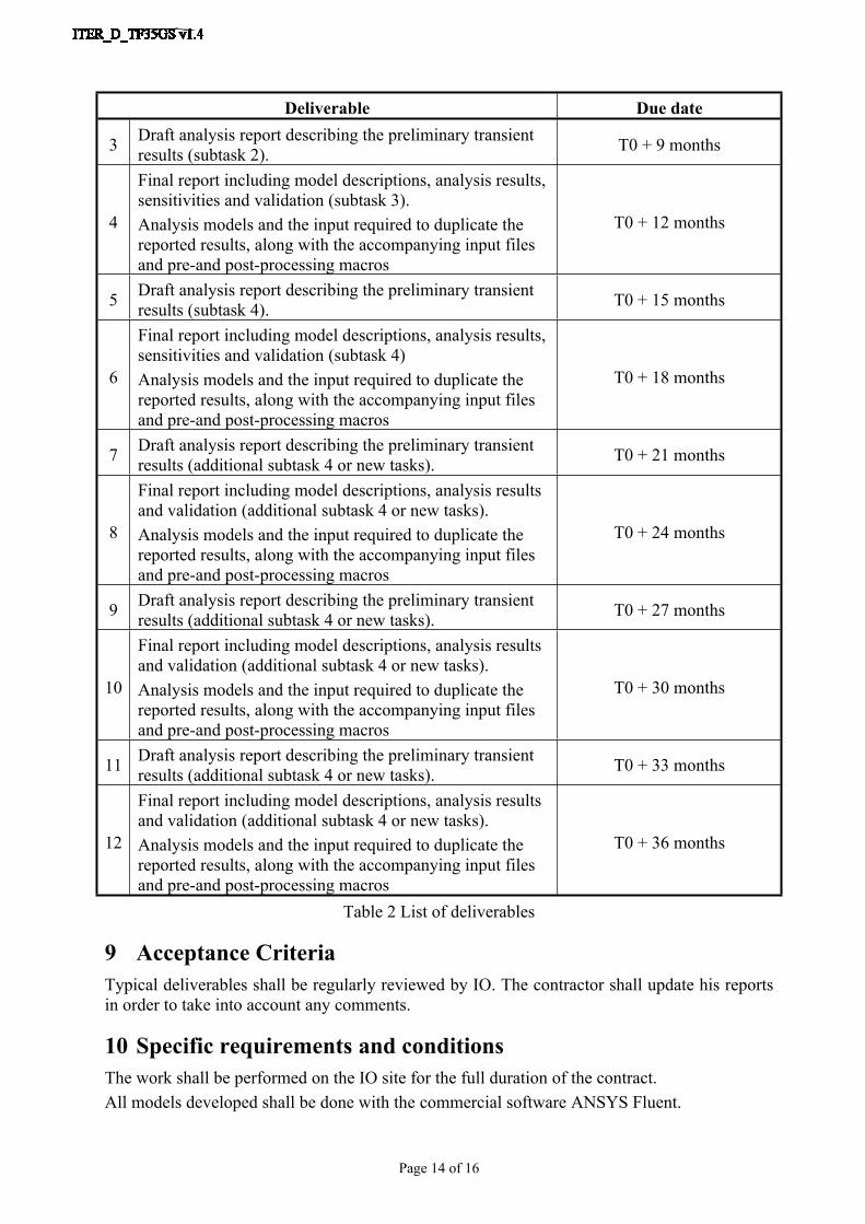
3 Draft analysis report describing the preliminary transient results (subtask 2). T0 + 9 months
4
Final report including model descriptions, analysis results, sensitivities and validation (subtask 3).Analysis models and the input required to duplicate the reported results, along with the accompanying input files and pre-and post-processing macros
T0 + 12 months
5 Draft analysis report describing the preliminary transient results (subtask 4). T0 + 15 months
6
Final report including model descriptions, analysis results, sensitivities and validation (subtask 4)Analysis models and the input required to duplicate the reported results, along with the accompanying input files and pre-and post-processing macros
T0 + 18 months
7 Draft analysis report describing the preliminary transient results (additional subtask 4 or new tasks). T0 + 21 months
8
Final report including model descriptions, analysis results and validation (additional subtask 4 or new tasks).Analysis models and the input required to duplicate the reported results, along with the accompanying input files and pre-and post-processing macros
T0 + 24 months
9 Draft analysis report describing the preliminary transient results (additional subtask 4 or new tasks). T0 + 27 months
10
Final report including model descriptions, analysis results and validation (additional subtask 4 or new tasks).Analysis models and the input required to duplicate the reported results, along with the accompanying input files and pre-and post-processing macros
T0 + 30 months
11 Draft analysis report describing the preliminary transient results (additional subtask 4 or new tasks). T0 + 33 months
12
Final report including model descriptions, analysis results and validation (additional subtask 4 or new tasks).Analysis models and the input required to duplicate the reported results, along with the accompanying input files and pre-and post-processing macros
T0 + 36 months
Table 2 List of deliverables
9 Acceptance CriteriaTypical deliverables shall be regularly reviewed by IO. The contractor shall update his reports in order to take into account any comments.
10 Specific requirements and conditionsThe work shall be performed on the IO site for the full duration of the contract.All models developed shall be done with the commercial software ANSYS Fluent.
Page 15 of 16
As the official language of the ITER project is English, reports shall be written in English.
The following skills and education level are required for the personnel supplied by the Contractor:
- University degree in engineering, or a combination of qualifications and experience acceptable to IO,
- Several years' working experience in the thermal-hydraulics and CFD analysis field,- Good knowledge of the CFD analysis procedures and on the use of analyses tools
(preference to ANSYS Fluent code is given),- Fluent in English both written and oral,- Ability to communicate effectively and to write clear and concise reports in English,- Knowledge of the use of Microsoft Office suite of software,- Good interpersonal, communication and organizational skills,- Ability to work effectively in a multi-cultural environment, and independently when
required.A good knowledge of the nuclear safety requirements (French regulator environment) would be appreciated.
11 Work Monitoring / Meeting ScheduleAs the contractor will be on site, progress will be monitored on a regular basis by the IO supervisor.
12 BreakdownThe main lines of delivery time breakdown are written in paragraph 8.
13 Quality Assurance (QA) requirementsThe organisation conducting these activities should have an ITER approved QA Program or an ISO 9001 accredited quality system.The general requirements are detailed in [7].Prior to commencement of the task, a Quality Plan must be submitted for IO approval giving evidence of the above and describing the organisation for this task; the skill of workers involved in the study; any anticipated sub-contractors; and giving details of who will be the independent checker of the activities (see [12]).Documentation developed as the result of this task shall be retained by the performer of the task or the DA organization for a minimum of 5 years and then may be discarded at the direction of the IO. The use of computer software to perform a safety basis task activity such as analysis and/or modelling, etc. shall be reviewed and approved by the IO prior to its use, in accordance with [13].
14 Safety requirementsITER is a Nuclear Facility identified in France by the number-INB-174 (“Installation Nucléaire de Base”).For Protection Important Components and in particular Safety Important Class components (SIC), the French Nuclear Regulation must be observed, in application of the Article 14 of the ITER Agreement.In such case the Contractors and Subcontractors must be informed that:
Page 16 of 16
- The Order 7th February 2012 applies to all the components important for the protection (PIC) and the activities important for the protection (PIA).
- The compliance with the INB-order must be demonstrated in the chain of external contractors.
- In application of article II.2.5.4 of the Order 7th February 2012, contracted activities for supervision purposes are also subject to a supervision done by the Nuclear Operator.
For the Protection Important Components, structures and systems of the nuclear facility, and Protection Important Activities the contractor shall ensure that a specific management system is implemented for his own activities and for the activities done by any Contractor and Subcontractor following the requirements of the Order 7th February 2012 [6].Support documents are [10] and [11].


![Lovejoy Hydraulics · 2018-01-31 · [For higher flow rates, consult Lovejoy Hydraulics Technical Engineering] Removable end caps for easy cleaning Close-tolerance port face locations](https://img.pdfslide.us/doc/110x75/5ea0429fd581b674464c2267/lovejoy-hydraulics-2018-01-31-for-higher-flow-rates-consult-lovejoy-hydraulics.jpg)