Distributed Radio Resource
Management in LTE-Advanced
Networks with Type 1 Relay
Nodes
Chen Sun
BEng, MEng
A Dissertation submitted in fulfilment of the requirements forthe award of Doctor of Philosophy (Ph.D.)
Dublin City University
School of Electronic Engineering
Supervisor: Dr. Xiaojun Wang
July 2014

Declaration
I hereby certify that this material, which I now submit for assessment
on the programme of study leading to the award of Ph.D is entirely my
own work, that I have exercised reasonable care to ensure that the work
is original, and does not to the best of my knowledge breach any law of
copyright, and has not been taken from the work of others save and to
the extent that such work has been cited and acknowledged within the
text of my work.
Signed:
Candidate ID No:
Date:
i

To my lovely wife and to my adorable son.
ii

Acknowledgements
This dissertation is the result of a four and half years research project
at the School of Electronic Engineering, Dublin City University, Ireland,
under the supervision and guidance of Dr. Xiaojun Wang. This research
project is co-financed by Dublin City University and Chinese Scholarship
Council.
First and foremost, I want to thank my dear parents. Your endless
love support me in these 4 years. You gave me your encouragement and
expectation to help me continue and complete the research project. Your
attitude towards work, people, and life always inspired me so much. You
are great parents I love you all!
An extra special acknowledgement goes to my dear wife, Ms. Lina
Duan. We have been together for eight years and have been married for
four years. In these years, you are always supporting my decision and
encouraging me to complete what I should do. Four-year long-distance
marriage made us stronger than ever. I do believe that we can handle
every difficulty in our future life. More importantly, I would like to thank
you for giving birth to my son. He is now my everything. I love you so
much.
I would like to greatly appreciate the significant help from my super-
visor, Dr. Xiaojun Wang. I am and will always be very glad to be your
student. Without you, it would not have been possible to complete this
doctoral thesis or even start this PhD study. Every moment I was facing
difficulties in academic and living, your help and suggestions would al-
ways be the key factor of overcoming the difficulties. Also, I would like
to acknowledge the great help from Prof. Weidong Wang from Beijing
University of Posts and Telecommunications, China. I appreciate your
constructive feedback.
I would to give big thanks to Dr. Gaofeng Cui, Dr. Zhiguo Qu and
Dr. Olga Ormond. After every discussion between you and me, many
excellent ideas and feedback would be obtained. My heartfelt thanks are
iii
given to my lovely colleagues, Xiaofei Wang, Yachao Zhou, Feng Guo,
Ming Zhao, Khalid Javeed, Brendan Cronin. It was and is a wonderful
time working with you.
Special thanks to my old friends, Haoxuan Li, Zhenhui Yuan, Lily
He, Longhao Zou, Xing Zheng, Jie Jin, Yongli Tang, Siyuan Sun, Yan
Liu. Thank you for the constructive feedback. I enjoy every moment we
sharing food and happiness together. I am so proud of being your friend.
I would like to extend a very special thank to the technical staff of
the School of Electronic Engineering, Dublin City University for their
valuable support.
Last but not the least, I gratefully acknowledge Dr. Chris Phillips,
Dr. Gabriel-Miro Muntean and Prof. Paul Whelan for organizing the
PhD defense and giving me constructive feedback.
iv
List of Publications
1. Chen Sun, Xiaojun Wang, Xiaofei Wang, Weidong Wang, Gaofeng
Cui, ”A Novel Route Selection Strategy in Decode-and- Forward
Relay Enhanced LTE-A Network”, 2011 IET International Con-
ference on Communication Technology and Application (IET IC-
CTA2011), Beijing, China, 14-16 Oct 2011.
2. Chen Sun, Weidong Wang, Gaofeng Cui, Xiaojun. Wang, ”Service-
aware bidirectional throughput optimisation route selection strat-
egy in LTE-Advanced networks”, IET Networks, Jan 2014, online
published, DOI:10.1049/iet-net.2012.0191.
3. Chen Sun, Weidong Wang, Yinghai Zhang, Xiaojun Wang, ”Dis-
tributed 2-hop proportional fair resource allocation in LTE-Advanced
networks”, Wireless Communications and Mobile Computing, AUG
2014, online published, DOI: 10.1002/wcm.2517
v
Contents
Acknowledgement iii
Publications v
Contents vi
Abstract ix
List of Figures x
List of Tables xiii
List of Abbreviations xiv
1 Introduction 1
1.1 Research Motivation . . . . . . . . . . . . . . . . . . . . . . . . . . . 1
1.2 Problem Statement . . . . . . . . . . . . . . . . . . . . . . . . . . . . 3
1.3 Thesis Contributions . . . . . . . . . . . . . . . . . . . . . . . . . . . 8
1.4 Thesis Outline . . . . . . . . . . . . . . . . . . . . . . . . . . . . . . . 10
2 Technical Background 12
2.1 Introduction . . . . . . . . . . . . . . . . . . . . . . . . . . . . . . . . 12
2.2 Evolution of 3GPP Mobile Networks . . . . . . . . . . . . . . . . . . 12
2.2.1 Global System for Mobile (GSM) Communication . . . . . . . 12
2.2.2 Universal Mobile Telecommunication System (UMTS) . . . . . 13
2.2.3 Long Term Evolution (LTE) . . . . . . . . . . . . . . . . . . . 15
2.3 LTE Physical Layer . . . . . . . . . . . . . . . . . . . . . . . . . . . . 15
2.3.1 Transmission Scheme . . . . . . . . . . . . . . . . . . . . . . . 15
2.3.2 Resource Grid . . . . . . . . . . . . . . . . . . . . . . . . . . . 17
2.3.3 Frame Structure . . . . . . . . . . . . . . . . . . . . . . . . . . 19
2.4 LTE System Structure . . . . . . . . . . . . . . . . . . . . . . . . . . 20
vi
CONTENTS
2.4.1 Network Architecture . . . . . . . . . . . . . . . . . . . . . . . 20
2.4.2 Radio Protocol Architecture . . . . . . . . . . . . . . . . . . . 22
2.5 LTE Radio Resource Management . . . . . . . . . . . . . . . . . . . . 23
2.5.1 Radio Admission Control . . . . . . . . . . . . . . . . . . . . . 24
2.5.2 Packet Scheduling . . . . . . . . . . . . . . . . . . . . . . . . . 25
2.5.3 Link Adaptation . . . . . . . . . . . . . . . . . . . . . . . . . 26
2.5.4 Power Control . . . . . . . . . . . . . . . . . . . . . . . . . . . 26
2.6 LTE-Advanced . . . . . . . . . . . . . . . . . . . . . . . . . . . . . . 28
2.6.1 Network Architecture with Relay . . . . . . . . . . . . . . . . 29
2.6.2 Types of Relay Nodes . . . . . . . . . . . . . . . . . . . . . . 29
2.6.3 Resource Partitioning for Relay Backhauling . . . . . . . . . . 33
2.7 Conclusion . . . . . . . . . . . . . . . . . . . . . . . . . . . . . . . . . 34
3 Service-Aware Adaptive Bidirectional Optimisation Route Selec-
tion 35
3.1 Introduction . . . . . . . . . . . . . . . . . . . . . . . . . . . . . . . . 35
3.2 Related work . . . . . . . . . . . . . . . . . . . . . . . . . . . . . . . 36
3.3 System model . . . . . . . . . . . . . . . . . . . . . . . . . . . . . . . 40
3.3.1 Cell Structure . . . . . . . . . . . . . . . . . . . . . . . . . . . 40
3.3.2 Radio Transmission Model . . . . . . . . . . . . . . . . . . . . 41
3.3.3 Scheduling Algorithms . . . . . . . . . . . . . . . . . . . . . . 42
3.4 Problem Formulation and Analysis . . . . . . . . . . . . . . . . . . . 43
3.5 Algorithm Description . . . . . . . . . . . . . . . . . . . . . . . . . . 45
3.6 Complexity Analysis . . . . . . . . . . . . . . . . . . . . . . . . . . . 47
3.7 Performance Evaluation . . . . . . . . . . . . . . . . . . . . . . . . . 47
3.7.1 Simulation Parameters . . . . . . . . . . . . . . . . . . . . . . 47
3.7.2 Results and Discussions . . . . . . . . . . . . . . . . . . . . . 50
3.8 Conclusion . . . . . . . . . . . . . . . . . . . . . . . . . . . . . . . . . 60
4 Distributed Two-hop Proportional Fair Resource Allocation 61
4.1 Introduction . . . . . . . . . . . . . . . . . . . . . . . . . . . . . . . . 61
4.2 Related Work . . . . . . . . . . . . . . . . . . . . . . . . . . . . . . . 62
4.2.1 Centralised Approaches . . . . . . . . . . . . . . . . . . . . . . 62
4.2.2 Distributed Approaches . . . . . . . . . . . . . . . . . . . . . 66
4.3 System Model and Assumptions . . . . . . . . . . . . . . . . . . . . . 70
4.3.1 Network Model . . . . . . . . . . . . . . . . . . . . . . . . . . 70
4.3.2 Channel Model Assumptions . . . . . . . . . . . . . . . . . . . 71
4.3.3 Two-hop Transmission Protocols . . . . . . . . . . . . . . . . 71
vii
CONTENTS
4.4 Problem Formulation . . . . . . . . . . . . . . . . . . . . . . . . . . . 74
4.5 Problem Relaxation . . . . . . . . . . . . . . . . . . . . . . . . . . . . 76
4.5.1 Adaptive PF Resource Partitioning . . . . . . . . . . . . . . . 76
4.5.2 Two-hop PF Resource Scheduling . . . . . . . . . . . . . . . . 79
4.6 Performance Evaluation . . . . . . . . . . . . . . . . . . . . . . . . . 85
4.6.1 Simulation Scenarios . . . . . . . . . . . . . . . . . . . . . . . 85
4.6.2 Performance Comparison in the OTH Protocol . . . . . . . . . 89
4.6.3 Performance Comparison in the STH Protocol . . . . . . . . . 94
4.6.4 Cumulative Distribution Function . . . . . . . . . . . . . . . . 101
4.6.5 Summary . . . . . . . . . . . . . . . . . . . . . . . . . . . . . 102
4.7 Conclusion . . . . . . . . . . . . . . . . . . . . . . . . . . . . . . . . . 102
5 Two-Hop Adaptive Partial Frequency Reusing 104
5.1 Introduction . . . . . . . . . . . . . . . . . . . . . . . . . . . . . . . . 104
5.2 Related Work . . . . . . . . . . . . . . . . . . . . . . . . . . . . . . . 105
5.3 System Model . . . . . . . . . . . . . . . . . . . . . . . . . . . . . . . 112
5.4 Generalised Proportional Fairness (GPF) Problem Formulation . . . . 113
5.5 Proportional Fair Joint Route Selection and Resource Partitioning
Algorithm for APFR . . . . . . . . . . . . . . . . . . . . . . . . . . . 114
5.5.1 A Near-Optimal Resource Partitioning Algorithm . . . . . . . 114
5.5.2 A Route Selection Algorithm for PF-APFR . . . . . . . . . . 119
5.6 Performance Evaluation . . . . . . . . . . . . . . . . . . . . . . . . . 120
5.6.1 Simulation Parameters . . . . . . . . . . . . . . . . . . . . . . 120
5.6.2 Simulation Results . . . . . . . . . . . . . . . . . . . . . . . . 122
5.7 Conclusion . . . . . . . . . . . . . . . . . . . . . . . . . . . . . . . . . 130
6 Conclusions and Future Work 131
6.1 Introduction . . . . . . . . . . . . . . . . . . . . . . . . . . . . . . . . 131
6.2 Contributions . . . . . . . . . . . . . . . . . . . . . . . . . . . . . . . 131
6.3 Future Works . . . . . . . . . . . . . . . . . . . . . . . . . . . . . . . 134
References 137
viii
Distributed Radio Resource Management in
LTE-Advanced Networks with Type 1 Relay
Nodes
Chen SunBEng, MEng
Abstract
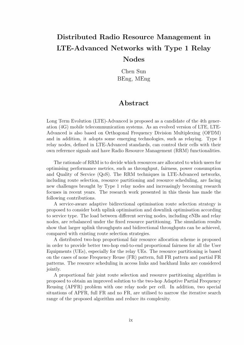
Long Term Evolution (LTE)-Advanced is proposed as a candidate of the 4th gener-ation (4G) mobile telecommunication systems. As an evolved version of LTE, LTE-Advanced is also based on Orthogonal Frequency Division Multiplexing (OFDM)and in addition, it adopts some emerging technologies, such as relaying. Type Irelay nodes, defined in LTE-Advanced standards, can control their cells with theirown reference signals and have Radio Resource Management (RRM) functionalities.
The rationale of RRM is to decide which resources are allocated to which users foroptimising performance metrics, such as throughput, fairness, power consumptionand Quality of Service (QoS). The RRM techniques in LTE-Advanced networks,including route selection, resource partitioning and resource scheduling, are facingnew challenges brought by Type 1 relay nodes and increasingly becoming researchfocuses in recent years. The research work presented in this thesis has made thefollowing contributions.
A service-aware adaptive bidirectional optimisation route selection strategy isproposed to consider both uplink optimisation and downlink optimisation accordingto service type. The load between different serving nodes, including eNBs and relaynodes, are rebalanced under the fixed resource partitioning. The simulation resultsshow that larger uplink throughputs and bidirectional throughputs can be achieved,compared with existing route selection strategies.
A distributed two-hop proportional fair resource allocation scheme is proposedin order to provide better two-hop end-to-end proportional fairness for all the UserEquipments (UEs), especially for the relay UEs. The resource partitioning is basedon the cases of none Frequency Reuse (FR) pattern, full FR pattern and partial FRpatterns. The resource scheduling in access links and backhaul links are consideredjointly.
A proportional fair joint route selection and resource partitioning algorithm isproposed to obtain an improved solution to the two-hop Adaptive Partial FrequencyReusing (APFR) problem with one relay node per cell. In addition, two specialsituations of APFR, full FR and no FR, are utilised to narrow the iterative searchrange of the proposed algorithm and reduce its complexity.
ix
List of Figures
1.1 A LTE-Advanced cell with RN deployment . . . . . . . . . . . . . . . 3
1.2 Resource allocation in single-hop networks . . . . . . . . . . . . . . . 4
1.3 RRM in the LTE-Advanced networks with Type 1 in-band half-duplexing
RNs . . . . . . . . . . . . . . . . . . . . . . . . . . . . . . . . . . . . 5
2.1 GSM network architecture . . . . . . . . . . . . . . . . . . . . . . . . 13
2.2 UMTS network architecture . . . . . . . . . . . . . . . . . . . . . . . 14
2.3 A Simple point-to-point transmission using OFDM [20] . . . . . . . . 16
2.4 Resource grid in the uplink and the downlink [22] . . . . . . . . . . . 18
2.5 Frame structure type 1 [22] . . . . . . . . . . . . . . . . . . . . . . . 19
2.6 Frame structure type 2 [22] . . . . . . . . . . . . . . . . . . . . . . . 20
2.7 LTE EPS architecture . . . . . . . . . . . . . . . . . . . . . . . . . . 21
2.8 LTE Radio Protocol Architecture . . . . . . . . . . . . . . . . . . . . 22
2.9 The mapping of related RRM function to the LTE radio protocol
layers [29] . . . . . . . . . . . . . . . . . . . . . . . . . . . . . . . . . 24
2.10 Simplified LTE-Advanced network architecture with relay node . . . . 30
2.11 Example of RN-to-UE transmission in one normal subframe and eNB-
to-RN transmission in a MBSFN subframe [24] . . . . . . . . . . . . . 34
3.1 Illustration of a LTE-Advanced macro cell . . . . . . . . . . . . . . . 40
3.2 Frame configuration, Variant-A and Variant-B . . . . . . . . . . . . . 49
3.3 Mean cell uplink throughput v.s. the number of users per cell in
Variant A . . . . . . . . . . . . . . . . . . . . . . . . . . . . . . . . . 51
3.4 Mean cell uplink throughput v.s. the number of users per cell in
Variant B . . . . . . . . . . . . . . . . . . . . . . . . . . . . . . . . . 51
3.5 Mean cell bidirectional throughput v.s. the number of users per cell
in Variant A . . . . . . . . . . . . . . . . . . . . . . . . . . . . . . . . 53
3.6 Mean cell bidirectional throughput v.s. the number of users per cell
in Variant B . . . . . . . . . . . . . . . . . . . . . . . . . . . . . . . . 53
x
LIST OF FIGURES
3.7 Mean uplink throughput of users with uplink-biased service v.s. the
number of users per cell in Variant A . . . . . . . . . . . . . . . . . . 55
3.8 Mean uplink throughput of users with uplink-biased service v.s. the
number of users per cell in Variant B . . . . . . . . . . . . . . . . . . 55
3.9 Mean downlink throughput of users with downlink-biased service v.s.
user number per cell in Variant A . . . . . . . . . . . . . . . . . . . . 56
3.10 Mean downlink throughput of users with downlink-biased service v.s.
user number per cell in Variant B . . . . . . . . . . . . . . . . . . . . 57
3.11 Mean cell uplink throughput v.s. the number of users per cell in
Variant A in 10 MHz and 50 PRBs . . . . . . . . . . . . . . . . . . . 57
3.12 Mean cell bidirectional throughput v.s. the number of users per cell
in Variant A in 10 MHz and 50 PRBs . . . . . . . . . . . . . . . . . . 58
3.13 CDF of uplink throughputs of uplink-biased UEs (60 UEs per cell) . . 59
3.14 Mean uplink throughputs of uplink-biased UEs v.s. distance from the
cell centre (60 UEs per cell) . . . . . . . . . . . . . . . . . . . . . . . 60
4.1 Illustration of a LTE-Advanced macro cell . . . . . . . . . . . . . . . 70
4.2 Orthogonal two-hop transmission protocol . . . . . . . . . . . . . . . 72
4.3 Simultaneous two-hop transmission protocol . . . . . . . . . . . . . . 72
4.4 An orthogonal reuse pattern in the orthogonal protocol . . . . . . . . 73
4.5 Full reuse pattern in the simultaneous protocol . . . . . . . . . . . . . 73
4.6 2/3 partial reuse pattern in the simultaneous protocol . . . . . . . . . 74
4.7 1/3 partial reuse pattern in the simultaneous protocol . . . . . . . . . 74
4.8 Cellular network layout and RN deployment . . . . . . . . . . . . . . 86
4.9 GPF factor (Macro UEs) v.s. RN numbers per cell in the OTH protocol 89
4.10 GPF factor (relay UEs) v.s. RN numbers per cell in the OTH protocol 90
4.11 Average macro UE throughput v.s. RN numbers per cell in the OTH
protocol . . . . . . . . . . . . . . . . . . . . . . . . . . . . . . . . . . 91
4.12 Average relay UE throughput v.s. RN numbers per cell in the OTH
protocol . . . . . . . . . . . . . . . . . . . . . . . . . . . . . . . . . . 91
4.13 5% worst macro UE throughput v.s. RN numbers per cell in the OTH
protocol . . . . . . . . . . . . . . . . . . . . . . . . . . . . . . . . . . 92
4.14 5% worst relay UE throughput v.s. RN numbers per cell in the OTH
protocol . . . . . . . . . . . . . . . . . . . . . . . . . . . . . . . . . . 93
4.15 GPF factor (Macro UEs) v.s. RN numbers per cell in the STH protocol 95
4.16 GPF factor (relay UEs) v.s. RN number per cell in the STH protocol 95
4.17 Average macro UE throughput v.s. RN number per cell in the STH
protocol . . . . . . . . . . . . . . . . . . . . . . . . . . . . . . . . . . 97
xi
LIST OF FIGURES
4.18 Average relay UE throughput v.s. RN number per cell in the STH
protocol . . . . . . . . . . . . . . . . . . . . . . . . . . . . . . . . . . 97
4.19 5% worst macro UE throughput v.s. RN number per cell in the STH
protocol . . . . . . . . . . . . . . . . . . . . . . . . . . . . . . . . . . 98
4.20 5% worst relay UE throughput v.s. RN number per cell in the STH
protocol . . . . . . . . . . . . . . . . . . . . . . . . . . . . . . . . . . 99
4.21 CDF of relay UE throughput . . . . . . . . . . . . . . . . . . . . . . 101
5.1 Cellular network layout with one RN . . . . . . . . . . . . . . . . . . 121
5.2 GPF factor v.s. RN transmitting power . . . . . . . . . . . . . . . . . 123
5.3 Average UE throughput v.s. RN transmitting power . . . . . . . . . 123
5.4 5% worst UE throughput v.s. RN transmitting power . . . . . . . . . 124
5.5 Jain’s fairness index v.s. RN transmitting power . . . . . . . . . . . . 125
5.6 GPF factor v.s. RN position . . . . . . . . . . . . . . . . . . . . . . . 126
5.7 Average UE throughput v.s. RN position . . . . . . . . . . . . . . . . 127
5.8 5% worst UE throughput v.s. RN position . . . . . . . . . . . . . . . 128
5.9 Jain’s fairness index v.s. RN position . . . . . . . . . . . . . . . . . . 129
xii
List of Tables
2.1 Resource block parameters [22] . . . . . . . . . . . . . . . . . . . . . 19
2.2 QCI parameters [18] . . . . . . . . . . . . . . . . . . . . . . . . . . . 25
2.3 CQI table [18] . . . . . . . . . . . . . . . . . . . . . . . . . . . . . . . 27
3.1 Traffic Model . . . . . . . . . . . . . . . . . . . . . . . . . . . . . . . 49
3.2 Comparison in mean cell uplink throughput . . . . . . . . . . . . . . 52
3.3 Comparison in mean cell bidirectional throughput . . . . . . . . . . . 54
3.4 Comparison in mean UE uplink throughput with uplink-biased services 54
4.1 Simulation parameters . . . . . . . . . . . . . . . . . . . . . . . . . . 87
4.2 The gains of the DTHPF scheme over the ARP+CRS scheme in the
OTH protocol . . . . . . . . . . . . . . . . . . . . . . . . . . . . . . . 94
4.3 The gains of the DTHPF scheme over the ARP+CRS scheme in the
OTH protocol . . . . . . . . . . . . . . . . . . . . . . . . . . . . . . . 100
5.1 Simulation parameters . . . . . . . . . . . . . . . . . . . . . . . . . . 120
5.2 The improvement of the proposed algorithm against the benchmark-
ing algorithm in different RN transmitting power . . . . . . . . . . . 126
5.3 The improvement of the proposed algorithm against the benchmark-
ing algorithm with different RN distances from the donor eNBs . . . 129
xiii

List of Abbreviations
2G the 2nd Generation
3G the 3rd Generation
3GPP the 3rd Generation Partnership Project
4G the 4th Generation
ABO Adaptive Bidirectional Optimisation
AF Amplify-and-Forward
AMBR Aggregate Maximum Bit Rate
AMC Adaptive Modulation and Coding
APFR Adaptive Partial Frequency Reusing
ARP Adaptive Resource Partitioning
ARP Allocation Retention Priority
ARQ Automatic Repeat Request
BS Base Station
BSC Base Station Controller
C-DFA Cell-colouring based Distributed Frequency Allocation
CDF Cumulative Distribution Function
CDMA Code Division Multiple Access
CDMA Code Division Multiple Access
CoMP Coordinated Multi-Point
xiv
LIST OF TABLES
CP Cyclic Prefix
CQI Channel Quality Indicator
CRS Common Reference Signal
CRS Conventional Resource Scheduling
CSI Channel State Information
DAA Dynamic Allocation Algorithm
DDFFA Dynamic Fractional Frequency Allocation
DF Decode-and-Forward
DFT Discrete Fourier Transform
DL Downlink
DTHPF Distributed Two-Hop Proportional Fair
DwPTS Downlink Pilot Timeslot
E-UTRAN Evolved Universal Terrestrial Radio Access Network
EDGE Enhanced Data rates for GSM Evolution
eNB evolved Node B
EPC Evolved Packet Core
EPS Evolved Packet System
ETSI the European Telecommunications Standards Institute
Fair-RU Fair-Resource-Unit
Fair-TP Fair-Throughput
FDD Frequency Division Duplex
FDM Frequency-Division Multiplexing
FFR Full Frequency Reusing
FFT Fast Fourier Transformation
xv
LIST OF TABLES
FR Frequency Reuse
FR Full Reuse
GBR Guaranteed Bit Rate
GGSN Gateway GPRS Support Node
GP Guard Period
GPF Generalised Proportional Fairness
GPRS General Packet Radio Service
GSM Global System for Mobile communications
HARQ Hybrid Automatic Repeat Request
HSDPA High Speed Downlink Packet Access
HSUPA High Speed Uplink Packet Access
ICG Interference Coordination Game
ICI Inter-Cell Interference
ICIC Inter-Cell Interference Coordination
ID Identifier
iFFT inverse Fast Fourier Transformation
IICS Integrated Interference Coordination Scheme
IMT International Mobile Telecommunications
IP Internet-Protocol
ISD Inter-Site Distance
ITU International Telecommunication Union
JRSRP Joint Route Selection and Resource Partitioning
KKT Karush-Kuhn-Tucker
LB-RS Load Balancing Relay Selection
xvi
LIST OF TABLES
LoBO Load-Balancing Opportunistic
LTE Long Term Evolution
MAC Medium Access Channel
MBSFN Multimedia Broadcast multicast service Single Frequency Network
MCS Modulation and Coding Scheme
MIMO Multi Input Multi Output
MME Mobility Management Entity
MS Mobile Station
MSC Mobile Switching Center
NAS Non-Access Stratum
NFR None Frequency Reusing
OFDM Orthogonal Frequency Division Multiplexing
OFDMA Orthogonal Frequency Division Multiple Access
OR Orthogonal Reuse
OTH Orthogonal Two-Hop
P-GW Packet Data Network Gateway
PAG Power Allocation Game
PAPR Peak-to-Average Power Ratio
PCA Pre-Configuration Algorithm
PDCCH Physical Downlink Control Channel
PDCP Packet Data Convergence Protocol
PDN Packet Data Network
PDN-GW Packet Data Network Gateway
PDSCH Physical Downlink Shared Channel
xvii
LIST OF TABLES
PF Proportional Fair
PFR Partial Frequency Reusing
PHY Physical Layer
PR Partial Reuse
PRB Physical Resource Block
PSTN Public Switched Telephone Network
QAM Quadrature Amplitude Modulation
QCI QoS Class Identifier
QoS Quality of Service
QPSK Quadrature Phase Shift Keying
RAC Radio Admission Control
RAG Resource Allocation Gap
RB Radio Bearer
RBAG Resource Block Assignment Game
RE Range Expansion
RLC Radio Link Control
RN Relay Node
RNC Radio Network Controller
RND RN Distance
RR Round-Robin
RRC Radio Resource Control
RRM Radio Resource Management
RSP Received Signal Power
S-GW Serving Gateway
xviii
LIST OF TABLES
SC-FDMA Single Carrier Frequency Division Multiple Access
SGSN Serving GPRS Support Node
SINR Signal to Interference plus Noise Ratio
SMS Short Messaging Service
SSAA Semi-Static Allocation Algorithm
STH Simultaneous Two-Hop
TD-SCDMA Time Division-Synchronous CDMA
TDD Time Division Duplex
TDM Time Division Multiplex
TDMA Time-Division Multiple-Access
TTI Transmission Time Interval
UE User Equipment
UL Uplink
UpPTS Uplink Pilot Timeslot
UTRAN UMTS Terrestrial Radio Access Network
WCDMA Wideband CDMA
WiMAX Worldwide Interoperability for Microwave Access
xix
Chapter 1
Introduction
1.1 Research Motivation
A mobile cellular telecommunication network is a wireless network providing mobile
services over land areas called cells. In each cell, mobile phones or devices are served
by at least one fixed transceiver called a base station. The two decades since the
early 1990s have witnessed tremendous development of mobile telecommunications
from the 2nd Generation (2G) mobile networks to the 4th Generation (4G) mo-
bile networks. The mobile telecommunication networks of new generations should
supply more and more users with ubiquitous services with high quality. In order
to satisfy this requirement, radio resources in different domains, such as time and
frequency, are controlled by Radio Resource Management (RRM) functionalities.
In different generation mobile networks, the RRM faces new-coming challenges and
need innovation.
Global System for Mobile communications (GSM) is usually recognised as the
most successful 2G standard series developed by the European Telecommunications
Standards Institute (ETSI). On July 1, 1991, the world’s first GSM call was made
in a city park in Helsinki, Finland, built by Telenokia and Siemens and operated by
Radiolinja [1]. The GSM, a digital, circuit-switched network, was expanded to Gen-
eral Packet Radio Service (GPRS)[2] and Enhanced Data rates for GSM Evolution
(EDGE)[3] in ways of packet switching and faster data rates, up to 473.6 kbit/s in
theory. Frequency-Division Multiplexing (FDM) and Time-Division Multiple-Access
(TDMA) [4] are used to allocate different time slots in multiple frequency bands to
different users. Therefore, the main RRM issues, such as channel allocation, power
1
control and handover techniques, are studied to exploit multi-user diversity, reduce
co-channel interference and manage user movement.
The 3rd Generation (3G) mobile telecommunication technologies are the stan-
dards that fulfil the International Mobile Telecommunications-2000 (IMT-2000) spec-
ifications by the International Telecommunication Union (ITU). Apart from voice
telephony and the Short Messaging Service (SMS) supported in 2G networks, more
applications are offered, such as mobile Internet access, fixed wireless Internet ac-
cess, video calls and mobile TV. Code Division Multiple Access (CDMA) technology
is used in three major 3G standards: Wideband CDMA (WCDMA) in Europe [5],
CDMA 2000 in the US [6] and Time Division-Synchronous CDMA (TD-SCDMA)
in China [7]. The High Speed Downlink Packet Access (HSDPA) and High Speed
Uplink Packet Access (HSUPA), which are evolved from the 3G networks, can now
support up to 14.4 Mbits/s data rates in the downlink and 5.76 Mbits/s data rates
in the uplink respectively. The inter-code interference feature of CDMA introduces
more challenges to the 3G networks, and more RRM techniques, such as admission
control, soft handover, load balancing and congestion control [8], are studied.
Facing the challenges from Worldwide Interoperability for Microwave Access
(WiMAX), the 3rd Generation Partnership Project (3GPP) organisation started
the Long Term Evolution (LTE) project [9] to support packet switching with an all-
Internet-Protocol (IP) network and achieve the peak data rate up to 100 Mbits/s
in the downlink and 50 Mbits/s in the uplink. In many countries and regions,
LTE has been deployed widely as a natural evolution of GSM and UMTS networks
and can be considered as a revolution in technique and performance. Orthogonal
Frequency Division Multiple Access (OFDMA) is used in the downlink and Single
Carrier Frequency Division Multiple Access (SC-FDMA) is adopted in the uplink.
The new RRM problems existing in the LTE networks include the Inter-Cell Interfer-
ence Coordination (ICIC) for improving cell-edge performance [10]and the resource
scheduling for utilising the multi-channel diversity [11].
Nonetheless, the LTE is not a real 4G network as in the commercial advertise-
ments, because it does not fulfil the requirements of the 4G specifications, IMT
Advanced [12], defined by ITU. Hence in September 2009, the 3GPP partners made
a formal submission to the ITU to propose LTE Release 10 and beyond (LTE-
Advanced) to be evaluated as a candidate of IMT-Advanced [13]. Therefore, the
requirements of LTE-Advanced are naturally decided to achieve or even enhance
IMT-Advanced requirements. Peak data rates of up to 1 Gbits/s in the downlink
and 500 Mbits/s in the uplink, and scalable bandwidth up to 100 MHz are expected.
2
Lower user and control plane latencies, larger VoIP capacity and better cell-edge
performance are also anticipated. These requirements will enable LTE-Advanced to
address increasing user requirements. Accordingly, the main issue in LTE-Advanced
is to develop new technologies allowing LTE-Advanced to meet the proposed targets.
Spectrum aggregation, relaying and Coordinated Multi-Point (CoMP) transmission
and reception are proposed as promising technologies in LTE Release 10 [14, 15].
Other important requirements of LTE-Advanced also include backward compatibil-
ity and spectrum flexibility [16]. Hence, LTE-Advanced should be considered as
an evolution rather than a revolution from LTE with better system performance,
different system structure and lower cost.
Relaying is one of the promising technologies in LTE-Advanced to expand cover-
age and enhance capacity. As Type 1 and Type 2 in-band half-duplex Relay Nodes
(RNs) have been defined in LTE-Advanced standards [14], in-band relaying brings
new challenges to the RRM. Thus, there is a need for some new RRM techniques in
relay enhanced LTE-Advanced networks.
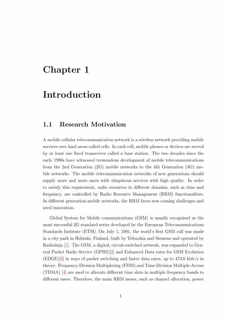
1.2 Problem Statement
eNBUE1
Backhaul link Direct link
Access linkRNk
Backhaul link
RN1
UE2
RN2
UEM
Figure 1.1: A LTE-Advanced cell with RN deployment
In a LTE-Advanced cell shown in Fig. 1.1, one or multiple RNs are deployed in
the cell-edge area. They are connected to an evolved Node B (eNB) through wireless
backhaul links. Thus, a cell-edge User Equipment (UE) can choose these RNs in
order to obtain potential extra performance gain by utilising two-hop transmission.
There are three types of links in the cell, i.e. eNB-RN links, RN-UE links and
3
eNB-UE links, which are named as backhaul links, access links and direct links
respectively.
……
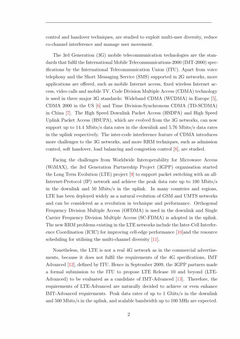
Figure 1.2: Resource allocation in single-hop networks
In single-hop networks, such as LTE networks without relays, the cells are se-
lected by the UEs based on the received signal power, and the resources in each
cell are allocated to the UEs in different manners to satisfy performance goals, as
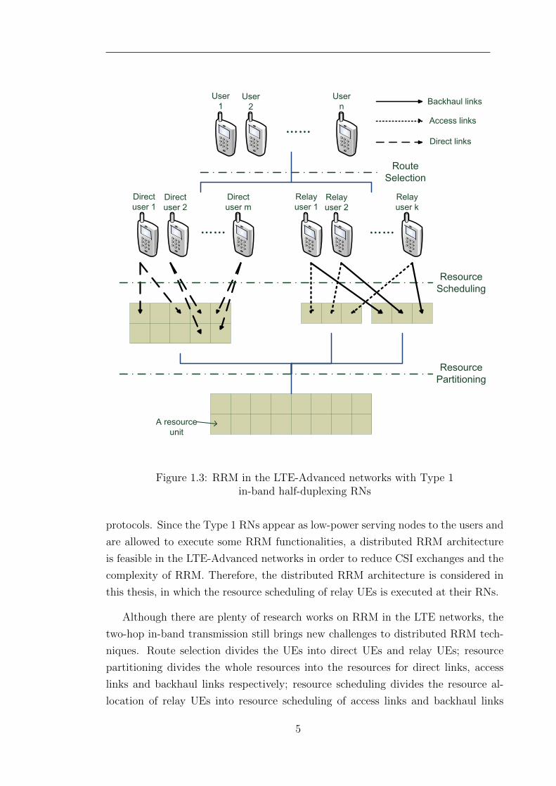
shown in Fig. 1.2. However, in the LTE-Advanced networks with RNs, Type 1 in-
band half-duplexing RNs are defined, which makes the resource allocation process of
UEs more complicated. As illustrated in Fig. 1.3, RRM in the LTE-Advanced net-
works with Type 1 in-band half-duplexing RNs decomposes the resource allocation
of UEs into three phases, including route selection, resource partitioning and re-
source scheduling. Route selection is used to decide the serving nodes for the UEs,
either eNBs or RNs. Hence, the UEs are divided into direct UEs and relay UEs
connecting to eNBs and RNs respectively. Resource partitioning divides a whole
time-frequency block into different resource segments for different links. Resource
scheduling allocates the resource segments of different links to their subscribed UEs.
These three phases of RRM can be executed in centralised manner or distributed
manner. When centralised RRM is applied, route selection, resource partitioning
and resource scheduling are determined together at the eNB of each cell. When the
decision is made, the Channel State Information (CSI) of access links ought to be
collected and fed back by the RNs. The frequent CSI exchange will cost a large
amount of signal load and is not time-efficient. Making decision for three phases
together will lead to high-complexity algorithms in the eNB. In addition, frequent
changes of route selection and resource partitioning bring challenges to signalling
4
……
A resource unit
Resource Scheduling
User 1
User 2
User n
……
Direct user 1
Direct user 2
Direct user m
……
Relayuser 1
Relay user 2
Relay user k
Route Selection
Resource Partitioning
Backhaul links
Access links
Direct links
Figure 1.3: RRM in the LTE-Advanced networks with Type 1in-band half-duplexing RNs
protocols. Since the Type 1 RNs appear as low-power serving nodes to the users and
are allowed to execute some RRM functionalities, a distributed RRM architecture
is feasible in the LTE-Advanced networks in order to reduce CSI exchanges and the
complexity of RRM. Therefore, the distributed RRM architecture is considered in
this thesis, in which the resource scheduling of relay UEs is executed at their RNs.
Although there are plenty of research works on RRM in the LTE networks, the
two-hop in-band transmission still brings new challenges to distributed RRM tech-
niques. Route selection divides the UEs into direct UEs and relay UEs; resource
partitioning divides the whole resources into the resources for direct links, access
links and backhaul links respectively; resource scheduling divides the resource al-
location of relay UEs into resource scheduling of access links and backhaul links
5
separately. Through these procedures, the balance between some elements of RRM
may be distorted. Therefore, the principles of designing distributed RRM techniques
in this thesis is ”rebalancing”.
The first and the foremost target of rebalancing are performance metrics. Pro-
portional fairness is considered as the common metric in this thesis, because it can
achieve an effective balance between increasing throughput and guaranteeing fair-
ness [17]. The proportional fairness in single-hop networks can be easily ensured,
however guaranteeing two-hop end-to-end proportional fairness should be considered
more carefully.
The problems and challenges in route selection, resource partitioning and re-
source scheduling are describe as follows:
Route Selection
A important challenge in the route selection is caused by the low transmitting power
of RNs, which is called uplink/downlink gain imbalance. For the UEs in the tra-
ditional single-hop LTE networks, the serving nodes are chosen according to the
largest received signal power. In the two-hop LTE-Advance networks, at least one
transmission route among single-hop direct links and two-hop links should be cho-
sen. Note that in this thesis only one route can be selected for each UE, and hence
cooperative relaying is not considered. Due to a large degree of difference between
the transmitting power of eNBs and RNs [14], the UEs in a certain area of a cell will
receive higher downlink signal power with larger path loss from the eNB and lower
downlink signal power with less path loss from the RN. For these UEs, the downlink
performance can be improved by the eNB. However, better uplink quality can be
provided by the RN because the RN receives larger signal power with less path loss
than the eNB from the UE. The performance gains provided by the RN in the up-
link and downlink are different. The traditional cell selection strategies neglect the
uplink/downlink gain imbalance because of the homogeneous transmitting charac-
teristics. Some route selection strategies aim at downlink optimisation, which prefer
to connect the UEs to the eNB for better downlink performance without optimal
uplink performance. Using some route selection strategies for the purpose of uplink
optimisation, the UEs are prone to access the RNs for better uplink performance
and their downlink gain will be decreased. Thus, a new balance between uplink op-
timisation and downlink optimisation should be achieved, either fixed for simplicity
and compatibility, or adaptive to the different data rate requirements in the uplink
6
and the downlink of different asymmetric UEs.
Resource Partitioning
Another research topic of interest is that assembling different types of links in a whole
spectrum brings challenges to resource partitioning. In order to support in-band
relaying and avoid serious interference at RNs, all subframes in a radio frame are
grouped into backhaul subframes and access subframes. In the backhaul subframes,
the backhaul links and the direct links share the resources. In the access subframes,
the direct and access links can share or reuse the resources in the access subframes.
Additionally, due to the limited buffer size of a RN, the aggregate throughputs of its
access links should approach the throughput of its backhaul link, called a two-hop
match. Through the above steps, the whole resources in the cell are partitioned
between these three types of links. A resources partitioning scheme can be fixed or
adaptive.
The challenge to the fixed resource partitioning is load imbalance. Because of
the randomness of UE location and smaller coverage of the RNs than that of the
eNBs, the numbers of UEs associating with the eNB and the RNs may change
dramatically from serving node to serving node. Thus, assigning the same amount
of resources to different serving nodes can cause load imbalance. Moreover, due to
limited buffering in the RNs, the aggregated throughput of access links should be
equal to the throughput of the corresponding backhaul link, which can be called
a ”two-hop match”. The unmatched two-hop will lead to resource waste either in
the access links or in the backhaul links, which can be considered as another form
of load imbalance. A load balancing mechanism is a requirement for fair resource
distribution and reducing resource waste. The benefit of fixed resource partitioning
is that an inter-cell interference coordination scheme can be applied.
The advantage of using adaptive resource partitioning is that every UE can
choose a transmission channel with the best condition and without load balancing.
However, in-band two-hop relaying brings two more challenges to designing adaptive
resource partitioning schemes. First, both the access links and the backhaul links of
two-hop transmission should occupy a different number of resources to transmit the
same amount of data, and these two links should satisfy the two-hop match. Second,
the requirements of in-band half-duplex relaying result in the whole resources being
partitioned into three parts, each part for one type of link. For instance, a radio
frame is partitioned into backhaul subframes for backhaul links and access subframes
7
for access links and direct links, and then the access subframes are orthogonally
shared, partially reused or fully reused by access links and direct links. Sharing,
fixed or adaptive two-hop reusing between access links and direct links may need
different resource partitioning methods. Adaptive partial reusing can achieve a
balance between increasing reused resource number and reducing interference caused
by frequency reusing. Besides, orthogonal sharing and full reusing can be considered
as two special cases of adaptive partial reusing.
Resource Scheduling
Last but not the least, resource scheduling is also one of the challenges to distributed
RRM. For the relay UEs, both the resources for the access links and the resources for
the backhaul links should be scheduled between them. For the purpose of optimising
two-hop end-to-end performance and satisfying the two-hop match, the resource
scheduling in the access links and the resource scheduling in the backhaul links need
a careful rebalancing in a two-hop resource scheduling algorithm. Different from
the conventional scheduling algorithm in the single-hop cellular networks, the two-
hop resource scheduling algorithms may consider the channel condition of access
links and backhaul links simultaneously and may be different with different resource
partitioning results.
1.3 Thesis Contributions
The research work presented in this thesis made the following contributions to the
RRM in relay enhanced LTE-Advanced networks:
• proposed a service-aware Adaptive Bidirectional Optimisation (ABO) route
selection strategy, which
– optimises both downlink performance and uplink performance. The bidi-
rectional throughput is maximised, which is the sum of the throughputs
of uplink and downlink. A balance between uplink optimisation and
downlink optimisation is achieved.
– achieves load balance between different serving nodes. Load balancing
is integrated into the proposed route selection strategy with fixed re-
source partitioning. Load imbalance is a natural consequence of random
8
UE distribution and fixed resource partitioning, which will cause some
performance loss.
– introduces service types into the proposed route selection algorithm. The
UEs with different service types have different requirements in the down-
link and the uplink. The bidirectional throughput is optimised adaptively
for the UEs according to the service type.
– provides larger uplink throughput without significant downlink through-
put loss shown in performance evaluation. In particular, the UEs with
large uplink requirement can obtain larger uplink throughput to improve
their quality of service.
• proposed a Distributed Two-Hop Proportional Fair (DTHPF) resource alloca-
tion algorithm, which
– provides better two-hop end-to-end proportional fairness for the relay
UEs. The data transmitted in the backhaul links should be retransmitted
in the access links. The two-hop end-to-end throughput is no more than
the throughput in the backhaul links and the aggregated throughput in
the access links. Due to various channel conditions in the access links and
unique channel condition in the corresponding backhaul link, two-hop
end-to-end proportional fairness for the relay UEs cannot be represented
by the single-hop proportional fairness.
– formulates the proportional fair resource allocation problem as a Gen-
eralised Proportional Fairness (GPF) problem. The GPF problem is
further decomposed into two sub-problems, a resource partitioning sub-
problem and a resource scheduling sub-problem, which are related to each
other. The proportional fair based adaptive resource partitioning has
been well studied in order to obtain an improved resource partitioning
results. Hence, the relationship between the resource numbers of access
links and backhaul links is made clear.
– considers different two-hop transmission protocols with different frequency
reusing patterns between access links and direct links. Simultaneous two-
hop transmission protocol with full frequency reusing and fixed partial
frequency reusing, and orthogonal two-hop transmission protocol draw
different resource number constraints between access links and backhaul
links.
– utilises the Lagrange multiplier method to determine an improved result
for resource scheduling in two hops simultaneously.
9
– provides better proportional fairness and larger 5% worst throughputs
with different RN numbers per cell.
• proposed a proportional fair joint route selection and resource partitioning
algorithm, which:
– formulates the two-hop adaptive partial frequency reusing problem be-
tween the access links and the direct links as a GPF problem. Propor-
tional fairness is considered as the metric of performance, which is an
effective compromise between throughput and fairness. Given that the
route selection has been determined, the two-hop adaptive partial fre-
quency reusing problem is transformed into a proportional fair based re-
source partitioning problem. The scenario with one relay node per sector
is considered.
– proposes a proportional fair resource partitioning algorithm in order to
obtain a near-optimal solution to the two-hop adaptive partial frequency
reusing problem.
– utilises two special situations, full frequency reusing and no frequency
reusing, to narrow the iterative search range of the proposed resource
partitioning algorithm and reduce its complexity. In these two special sit-
uations, there are many effective algorithms to acquire their near-optimal
resource partitioning results.
– proposes a proportional fair route selection algorithm in the determined
cell. Based on the assumed resource partitioning results, the proposed
route selection algorithm estimates the achievable data rates when choos-
ing single-hop link and two-hop links.
– has evaluated the performance of the proposed joint proportional fair
resource partitioning and route selection scheme. Compared with tradi-
tional resource partitioning and route selection schemes, it can achieve
larger throughput and better fairness, and thus larger proportional fair-
ness.
1.4 Thesis Outline
This thesis includes 6 chapters and 1 appendix. The first chapter is the introduction
and the last chapter concludes the thesis. In the first chapter, the motivation of the
10
research in this thesis is introduced, the problem existing in the scope of the thesis
is analysed and stated, and then the main contributions of this thesis are detailed.
A brief description of the following chapters is given below:
• Chapter 2 introduces the necessary technical background of the research work
in this thesis.
• Chapter 3 proposes a service-aware Adaptive Bidirectional Optimisation (ABO)
route selection strategy. The current related research and the system models
are also introduced. Benchmarking the performance of the proposed ABO
strategy is also presented.
• Chapter 4 proposes a Distributed Two-Hop Proportional Fair (DTHPF) re-
source allocation algorithm. The current related research, the system models,
the problem formulation and the problem relaxation are included. The per-
formance of the proposed DTHPF algorithm is evaluated and compared with
conventional proportional fair resource allocation algorithms.
• Chapter 5 proposes a proportional fair joint route selection and resource parti-
tioning algorithm for the Adaptive Partial Frequency Reusing (APFR) prob-
lem. The current related research is reviewed and the system models are
described. A proportional fair joint route selection and resource partitioning
algorithm is proposed. The effectiveness of the proposed algorithms is evalu-
ated through performance simulations.
• Chapter 6 concludes the thesis and indicates some potential future research
directions.
11
Chapter 2
Technical Background
2.1 Introduction
This chapter presents the background technologies related to the research in this
thesis. First, the network structures and the multiple access techniques of GSM,
UMTS and LTE are described briefly. As important background techniques of RRM,
the radio transmission techniques, the resource grid, the system structure and the
RRM functions in LTE networks are depicted. Then, LTE-Advanced with relaying
technology are introduced briefly, as the evolution of LTE. Finally, the classification
of relay nodes and the principles of two-hop transmission are presented.
2.2 Evolution of 3GPP Mobile Networks
2.2.1 Global System for Mobile (GSM) Communication
The GSM is the most successful mobile cellular network standard until now. It has
given guidelines for the following mobile network generations. As shown in Fig. 2.1,
the GSM radio network consists of several cells. Each cell controlled by a Base Sta-
tion (BS) is a geographical representation of the coverage area within which the BS
can send and receive data. Cells are commonly illustrated by hexagonal shapes for
simplicity. In each cell, a number of Mobile Stations (MSs), representing the users,
are served. The wireless link from the BS to the MS is named as Downlink (DL) and
the other direction is named as Uplink (UL). Several BSs are controlled by the Base
Station Controller (BSC) for RRM. The BSC is connected to the GSM core network,
12

including a Mobile Switching Center (MSC) and some databases. The MSC handles
some RRM functions and deliver the data to the external networks. The databases
are responsible for operation functionalities, such as mobility management, user in-
formation storing, service controlling functions and billing. The external networks
include Public Switched Telephone Network (PSTN) or other GSM networks. The
details of the GSM is given in [4].
External networks
BS
BS
BSC MSC
E-UTRAN
Abis
MS
MS
MS
MS
Um
Um
Um
Um
A
HLR/VLRAUC/EIR
Core Network
HLR: Home Location Register;VLR: Visitor Location Register;AUC: Authentication Center;EIR: Equipment Identification Register
Abis
Figure 2.1: GSM network architecture
The GSM uses Time Division Multiple Access (TDMA) based on Frequency
Division Multiplexing (FDM) as the multiple access scheme. The FDM in the GSM
divides the whole spectrum into several carrier frequency bands with the width of
200 kHz. A frame in each carrier frequency band is then divided into 8 time slots
using TDMA. Each time slot can be used by a MS for transmission. In the GSM,
Frequency Division Duplex (FDD) is used to separate the downlink frequency band
from the uplink. A guard frequency band is needed between a downlink frequency
band and a uplink frequency band.
2.2.2 Universal Mobile Telecommunication System (UMTS)
The UMTS network is structured similarly to GSM with several modifications, which
is shown in Fig. 2.2. The radio access network in UMTS, called UMTS Terrestrial
Radio Access Network (UTRAN), consists of Radio Network Controller (RNC) and
several NodeBs (which represent the UMTS base stations). The UMTS core network
supports both circuit switching and packet switching. The circuit switching is used
to carry voice services, whereas packet switching is used for data services, like web
13
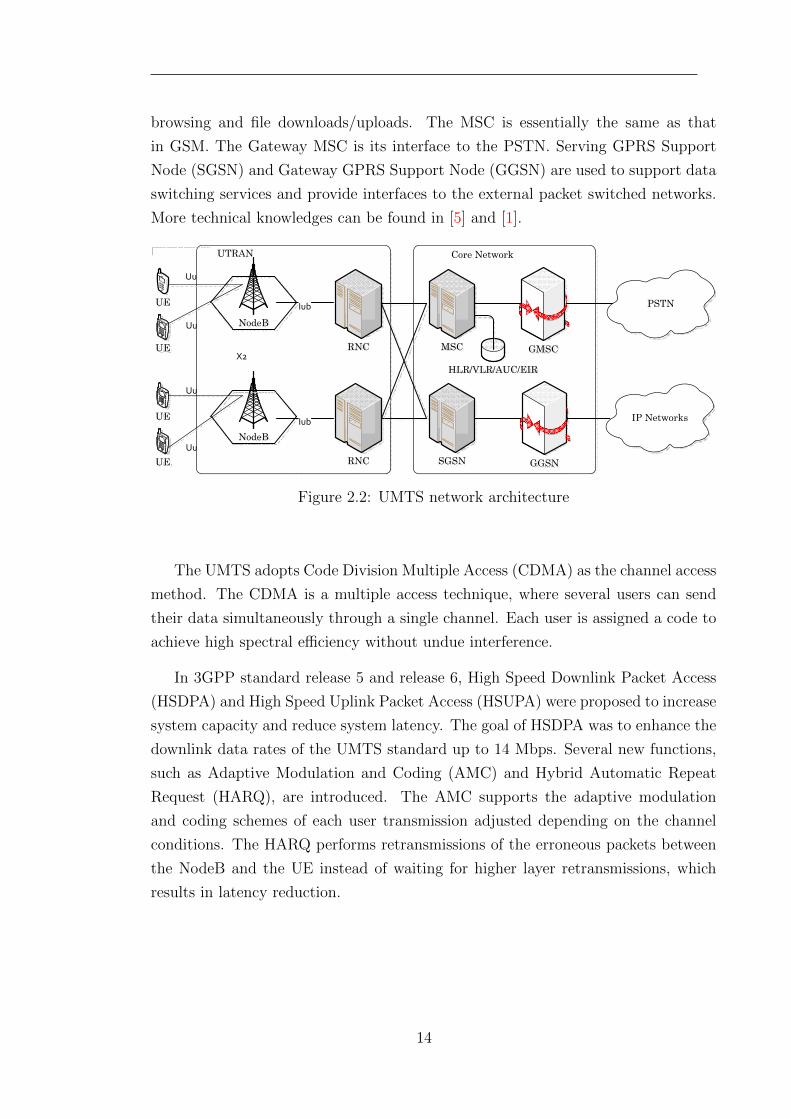
browsing and file downloads/uploads. The MSC is essentially the same as that
in GSM. The Gateway MSC is its interface to the PSTN. Serving GPRS Support
Node (SGSN) and Gateway GPRS Support Node (GGSN) are used to support data
switching services and provide interfaces to the external packet switched networks.
More technical knowledges can be found in [5] and [1].
MSC
NodeB
NodeB
SGSN
GMSC
GGSN
PSTNIub
Iub
UTRAN Core Network
X2
UE
UE
UE
UE
Uu
Uu
Uu
Uu
RNC
RNC
IP Networks
HLR/VLR/AUC/EIR
Figure 2.2: UMTS network architecture
The UMTS adopts Code Division Multiple Access (CDMA) as the channel access
method. The CDMA is a multiple access technique, where several users can send
their data simultaneously through a single channel. Each user is assigned a code to
achieve high spectral efficiency without undue interference.
In 3GPP standard release 5 and release 6, High Speed Downlink Packet Access
(HSDPA) and High Speed Uplink Packet Access (HSUPA) were proposed to increase
system capacity and reduce system latency. The goal of HSDPA was to enhance the
downlink data rates of the UMTS standard up to 14 Mbps. Several new functions,
such as Adaptive Modulation and Coding (AMC) and Hybrid Automatic Repeat
Request (HARQ), are introduced. The AMC supports the adaptive modulation
and coding schemes of each user transmission adjusted depending on the channel
conditions. The HARQ performs retransmissions of the erroneous packets between
the NodeB and the UE instead of waiting for higher layer retransmissions, which
results in latency reduction.
14
2.2.3 Long Term Evolution (LTE)
The LTE project was Initiated in 2004. In December 2008, 3GPP standard Re-
lease 8 was frozen, which has been the basis for the first wave of LTE equipment.
Now, the LTE (both radio and core network evolution) is on the market. The
study of the LTE focused on developing an Evolved Universal Terrestrial Radio Ac-
cess Network (E-UTRAN) architecture and adapting better radio multiple access
technologies. Orthogonal Frequency Division Multiplexing (OFDM)-based multiple
access schemes, Orthogonal Frequency Division Multiple Access (OFDMA) in the
downlink and Single Carrier Frequency Division Multiple Access (SC-FDMA) in the
uplink, are adopted. The main targets and requirements of LTE are described in
[18], including
• Scalable bandwidth 1.25, 1.6, 2.5, 5, 10, 15 and 20 MHz
• Significantly increased peak data rate, up to 100 Mbps in the downlink and
50 Mbps in the uplink
• Shorter latency, less than 100 ms from an idle state to an active state in
control-plane and less than 5 ms in user-plane
• Supporting All-IP architecture
2.3 LTE Physical Layer
2.3.1 Transmission Scheme
In the LTE E-UTRAN, the multiple access schemes are based on OFDM. OFDMA
scheme is used in the downlink and SC-FDMA scheme is used in the uplink. The
reason why OFDMA is applied in the LTE downlink is its robust features against
frequency selective channels. In order to provide lower peak-to-average ratio between
the transmitted signals, SC-FDMA is used in the uplink transmission, which is
beneficial for saving batter life of mobile devices.
OFDM
OFDM is actually a frequency division multiplexing scheme used as a digital multi-
carrier modulation method [19]. The long history of the OFDM technique has
witnessed its growing popularity in wireless and wired networking. Due to recent
15
enhancements in digital processing technology, OFDM has been accepted for wireless
high-speed communications in many standards.
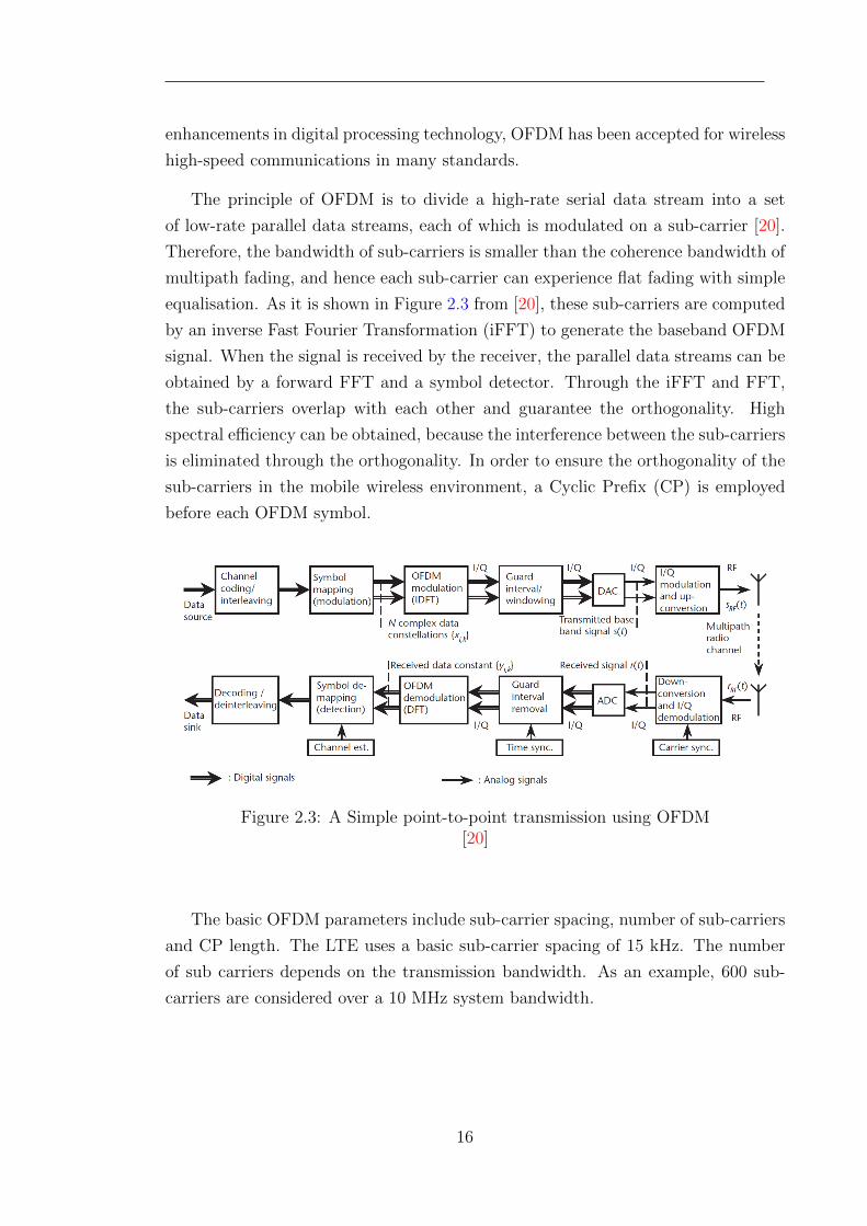
The principle of OFDM is to divide a high-rate serial data stream into a set
of low-rate parallel data streams, each of which is modulated on a sub-carrier [20].
Therefore, the bandwidth of sub-carriers is smaller than the coherence bandwidth of
multipath fading, and hence each sub-carrier can experience flat fading with simple
equalisation. As it is shown in Figure 2.3 from [20], these sub-carriers are computed
by an inverse Fast Fourier Transformation (iFFT) to generate the baseband OFDM
signal. When the signal is received by the receiver, the parallel data streams can be
obtained by a forward FFT and a symbol detector. Through the iFFT and FFT,
the sub-carriers overlap with each other and guarantee the orthogonality. High
spectral efficiency can be obtained, because the interference between the sub-carriers
is eliminated through the orthogonality. In order to ensure the orthogonality of the
sub-carriers in the mobile wireless environment, a Cyclic Prefix (CP) is employed
before each OFDM symbol.
Figure 2.3: A Simple point-to-point transmission using OFDM[20]
The basic OFDM parameters include sub-carrier spacing, number of sub-carriers
and CP length. The LTE uses a basic sub-carrier spacing of 15 kHz. The number
of sub carriers depends on the transmission bandwidth. As an example, 600 sub-
carriers are considered over a 10 MHz system bandwidth.
16
OFDMA
The Orthogonal Frequency Division Multiple Access (OFDMA) scheme is achieved
by assigning different sub-carriers to different users. Thus, the interference in
OFDMA systems is mainly generated between the users in different cells reusing
the same sub-carriers. The mitigation of Inter-Cell Interference (ICI) is a hot re-
search issue of RRM in LTE and LTE-Advanced. Differentiated QoS levels are
supported by scheduling the sub-carriers between the users.
One of the major drawbacks of OFDMA is the high Peak-to-Average Power Ratio
(PAPR) of the transmitted signals [21]. The signals with a high PAPR require
highly linear power amplifiers, which bring a heavy burden to portable wireless
devices with low power efficiency. Meanwhile, another problem of OFDMA in the
uplink transmission is the inevitable frequency offset of the reference signals. This
frequency offset will destroy the orthogonality of uplink transmissions, and thus
introduce inter-channel interference.
SC-FDMA
Single Carrier Frequency Division Multiple Access (SC-FDMA) is introduced in
LTE as an uplink multiple access scheme due to its distinguishing feature of lower
PAPR. The SC-FDMA transmitters use different orthogonal sub-carriers to transmit
symbols, which are first preprocessed by a Discrete Fourier Transform (DFT) block.
Therefore, the SC-FDMA sub-carriers are transmitted sequentially rather than in
parallel, resulting in lower PAPR of the signals. Besides, it also has a low sensitivity
to carrier frequency offset. However, the main drawbacks of SC-FDMA are lower
performance than OFDMA and complex signal processing at the BS side.
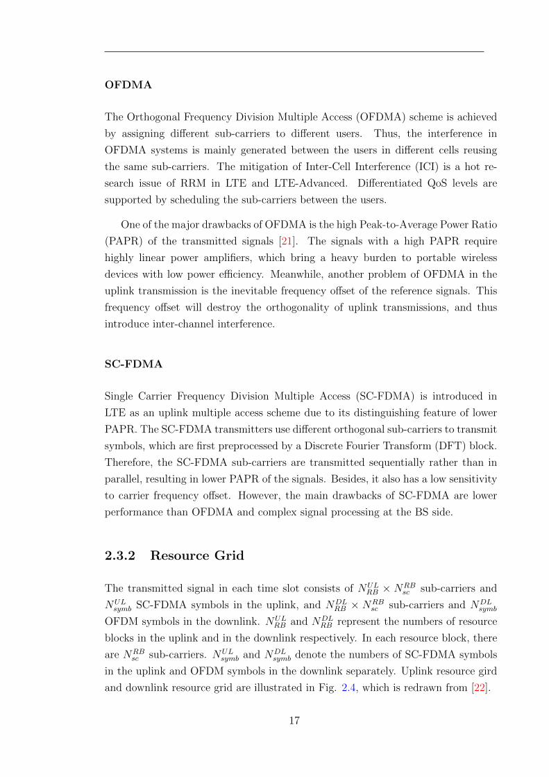
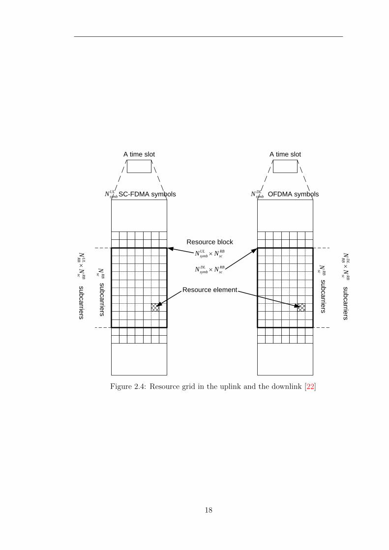
2.3.2 Resource Grid
The transmitted signal in each time slot consists of NULRB × NRB
sc sub-carriers and
NULsymb SC-FDMA symbols in the uplink, and NDL
RB × NRBsc sub-carriers and NDL
symb
OFDM symbols in the downlink. NULRB and NDL
RB represent the numbers of resource
blocks in the uplink and in the downlink respectively. In each resource block, there
are NRBsc sub-carriers. NUL
symb and NDLsymb denote the numbers of SC-FDMA symbols
in the uplink and OFDM symbols in the downlink separately. Uplink resource gird
and downlink resource grid are illustrated in Fig. 2.4, which is redrawn from [22].
17
SC-FDMA symbols
subcarriers
subcarriers
A time slot
ULsymbN
UL
RBRB
scN
N
RBsc
NResource element
Resource blockUL RBsymb scN N
OFDMA symbols
subcarriers
subcarriers
A time slot
DLsymbN
DL
RBRB
scN
N
RBsc
N
DL RBsymb scN N
Figure 2.4: Resource grid in the uplink and the downlink [22]
18
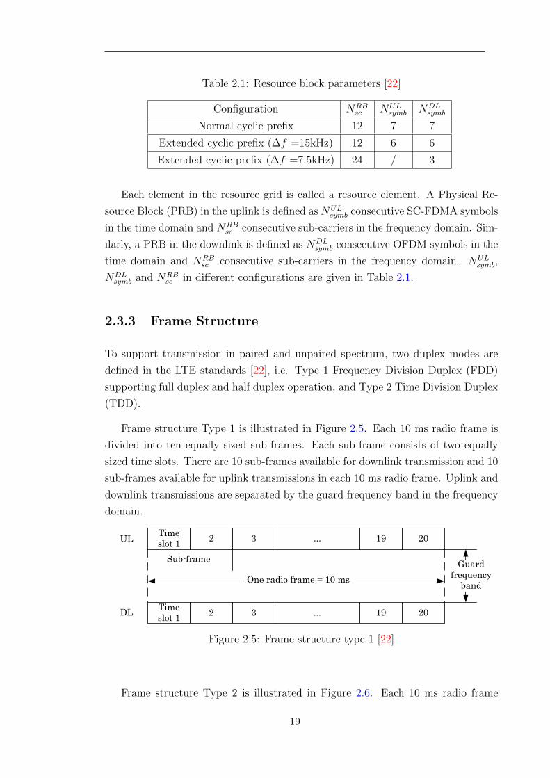
Table 2.1: Resource block parameters [22]
Configuration NRBsc NUL
symb NDLsymb
Normal cyclic prefix 12 7 7
Extended cyclic prefix (∆f =15kHz) 12 6 6
Extended cyclic prefix (∆f =7.5kHz) 24 / 3
Each element in the resource grid is called a resource element. A Physical Re-
source Block (PRB) in the uplink is defined as NULsymb consecutive SC-FDMA symbols
in the time domain and NRBsc consecutive sub-carriers in the frequency domain. Sim-
ilarly, a PRB in the downlink is defined as NDLsymb consecutive OFDM symbols in the
time domain and NRBsc consecutive sub-carriers in the frequency domain. NUL
symb,
NDLsymb and NRB
sc in different configurations are given in Table 2.1.
2.3.3 Frame Structure
To support transmission in paired and unpaired spectrum, two duplex modes are
defined in the LTE standards [22], i.e. Type 1 Frequency Division Duplex (FDD)
supporting full duplex and half duplex operation, and Type 2 Time Division Duplex
(TDD).
Frame structure Type 1 is illustrated in Figure 2.5. Each 10 ms radio frame is
divided into ten equally sized sub-frames. Each sub-frame consists of two equally
sized time slots. There are 10 sub-frames available for downlink transmission and 10
sub-frames available for uplink transmissions in each 10 ms radio frame. Uplink and
downlink transmissions are separated by the guard frequency band in the frequency
domain.
Time slot 1 2 3 ... 19 20
Sub-frame
One radio frame = 10 ms
Time slot 1 2 3 ... 19 20
UL
DL
Guard frequency
band
Figure 2.5: Frame structure type 1 [22]
Frame structure Type 2 is illustrated in Figure 2.6. Each 10 ms radio frame
19
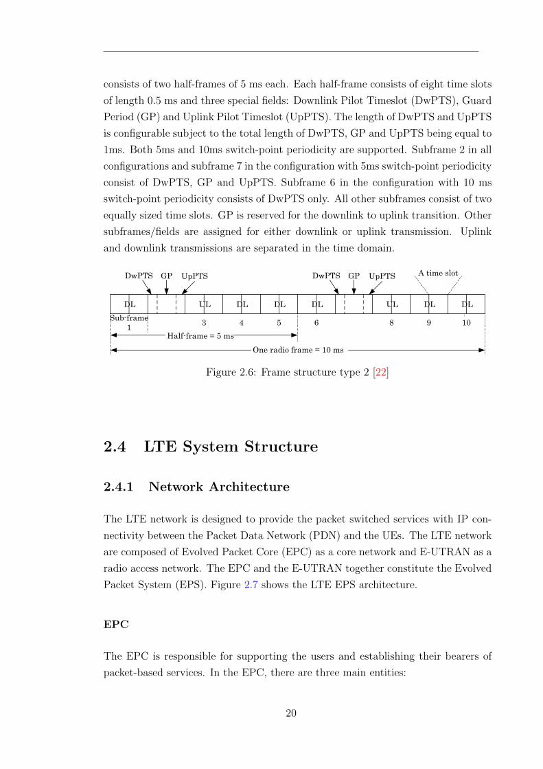
consists of two half-frames of 5 ms each. Each half-frame consists of eight time slots
of length 0.5 ms and three special fields: Downlink Pilot Timeslot (DwPTS), Guard
Period (GP) and Uplink Pilot Timeslot (UpPTS). The length of DwPTS and UpPTS
is configurable subject to the total length of DwPTS, GP and UpPTS being equal to
1ms. Both 5ms and 10ms switch-point periodicity are supported. Subframe 2 in all
configurations and subframe 7 in the configuration with 5ms switch-point periodicity
consist of DwPTS, GP and UpPTS. Subframe 6 in the configuration with 10 ms
switch-point periodicity consists of DwPTS only. All other subframes consist of two
equally sized time slots. GP is reserved for the downlink to uplink transition. Other
subframes/fields are assigned for either downlink or uplink transmission. Uplink
and downlink transmissions are separated in the time domain.
Sub-frame 1 3 4 5 6 8 9 10
DwPTS GP UpPTS DwPTS GP UpPTS A time slot
One radio frame = 10 ms
ULDL ULDL DL DL DL DL
Half-frame = 5 ms
Figure 2.6: Frame structure type 2 [22]
2.4 LTE System Structure
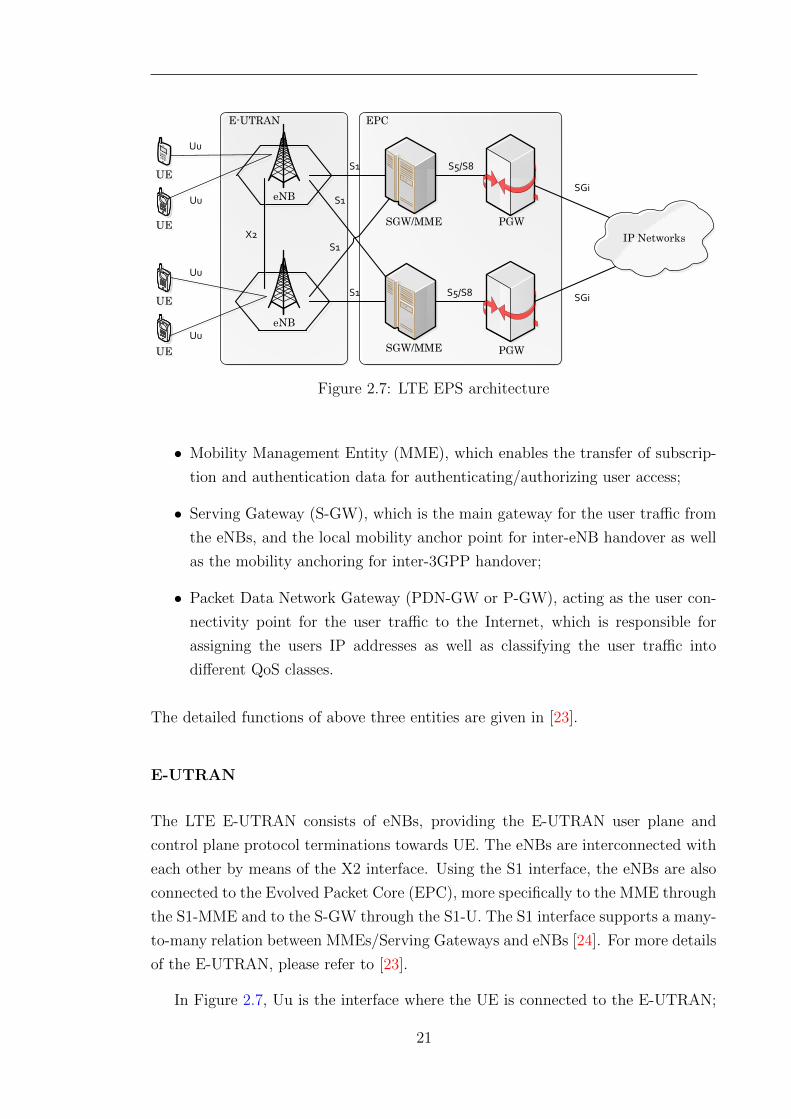
2.4.1 Network Architecture
The LTE network is designed to provide the packet switched services with IP con-
nectivity between the Packet Data Network (PDN) and the UEs. The LTE network
are composed of Evolved Packet Core (EPC) as a core network and E-UTRAN as a
radio access network. The EPC and the E-UTRAN together constitute the Evolved
Packet System (EPS). Figure 2.7 shows the LTE EPS architecture.
EPC
The EPC is responsible for supporting the users and establishing their bearers of
packet-based services. In the EPC, there are three main entities:
20
IP Networks
eNB
eNB
SGW/MME
SGW/MME PGW
PGW
E-UTRAN EPC
S1
S1
S1
S1
X2
S5/S8
S5/S8 SGi
SGiUEUE
UEUE
UEUE
UEUE
Uu
Uu
Uu
Uu
Figure 2.7: LTE EPS architecture
• Mobility Management Entity (MME), which enables the transfer of subscrip-
tion and authentication data for authenticating/authorizing user access;
• Serving Gateway (S-GW), which is the main gateway for the user traffic from
the eNBs, and the local mobility anchor point for inter-eNB handover as well
as the mobility anchoring for inter-3GPP handover;
• Packet Data Network Gateway (PDN-GW or P-GW), acting as the user con-
nectivity point for the user traffic to the Internet, which is responsible for
assigning the users IP addresses as well as classifying the user traffic into
different QoS classes.
The detailed functions of above three entities are given in [23].
E-UTRAN
The LTE E-UTRAN consists of eNBs, providing the E-UTRAN user plane and
control plane protocol terminations towards UE. The eNBs are interconnected with
each other by means of the X2 interface. Using the S1 interface, the eNBs are also
connected to the Evolved Packet Core (EPC), more specifically to the MME through
the S1-MME and to the S-GW through the S1-U. The S1 interface supports a many-
to-many relation between MMEs/Serving Gateways and eNBs [24]. For more details
of the E-UTRAN, please refer to [23].
In Figure 2.7, Uu is the interface where the UE is connected to the E-UTRAN;
21
S5/S8 is the interface between S-GW and P-GW; and SGi is used to access the
external IP networks.
2.4.2 Radio Protocol Architecture
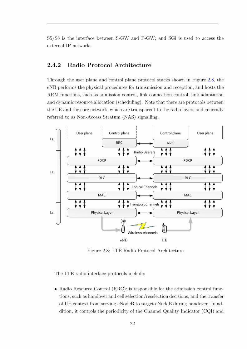
Through the user plane and control plane protocol stacks shown in Figure 2.8, the
eNB performs the physical procedures for transmission and reception, and hosts the
RRM functions, such as admission control, link connection control, link adaptation
and dynamic resource allocation (scheduling). Note that there are protocols between
the UE and the core network, which are transparent to the radio layers and generally
referred to as Non-Access Stratum (NAS) signalling.
RRC
PDCP
RLC
MAC
Physical Layer
User plane Control plane
Radio Bearers
Logical Channels
Transport Channels
L3
L2
L1
eNB
RRC
PDCP
RLC
MAC
Physical Layer
Control plane User plane
UE
Wireless channels
Figure 2.8: LTE Radio Protocol Architecture
The LTE radio interface protocols include:
• Radio Resource Control (RRC): is responsible for the admission control func-
tions, such as handover and cell selection/reselection decisions, and the transfer
of UE context from serving eNodeB to target eNodeB during handover. In ad-
dition, it controls the periodicity of the Channel Quality Indicator (CQI) and
22
is also responsible for the setup and maintenance of the radio bearers [25].
• Packet Data Convergence Protocol (PDCP): is responsible for compressing
the IP header for better efficiency over the radio interface. This layer also
performs additional functionalities, e.g., ciphering and integrity protection. A
detailed description of the PDCP functionality can be found in [26].
• Radio Link Control (RLC): is responsible for the segmentation and concate-
nation of the PDCP packets. It also performs retransmissions and guaran-
tees in-sequence delivery of the packets to the higher layers. The RLC also
performs error corrections using the well-known Automatic Repeat Request
(ARQ) method. A detailed description of the PDCP functionality can be
found in [27].
• Medium Access Channel (MAC): is responsible for scheduling PRBs between
different UEs in both uplink and downlink. Together with the scheduling
functionality, the MAC layer controls the uplink and downlink physical layer
retransmission to correct errors through the Hybrid Automatic Repeat Request
(HARQ) mechanism. In addition, it also performs transport block format
selection as part of the link adaptation functionality [28].
• Physical Layer (PHY): is responsible for radio related issues: e.g., modu-
lation/demodulation, coding/decoding, Multi Input Multi Output (MIMO)
techniques.
The physical layer carries the transport channels provided by the MAC layer.
The MAC layer offers the logical channels to the RLC layer. Above the RLC layer,
there is the PDCP layer. Layer 2 provides upward radio bearers. Signalling Radio
Bearers carry the RRC signalling messages. Correspondingly the user plane Radio
Bearers (RBs) carry the user data.
2.5 LTE Radio Resource Management
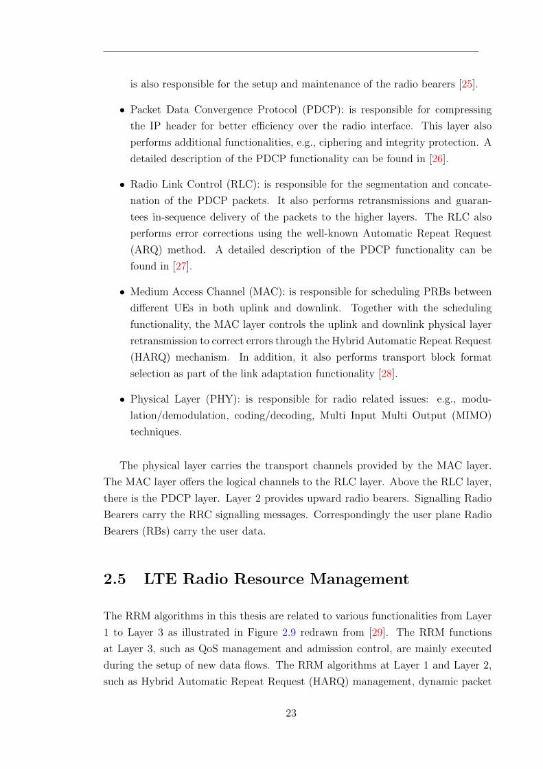
The RRM algorithms in this thesis are related to various functionalities from Layer
1 to Layer 3 as illustrated in Figure 2.9 redrawn from [29]. The RRM functions
at Layer 3, such as QoS management and admission control, are mainly executed
during the setup of new data flows. The RRM algorithms at Layer 1 and Layer 2,
such as Hybrid Automatic Repeat Request (HARQ) management, dynamic packet
23
scheduling and link adaptation, are highly dynamic functions with new actions con-
ducted every Transmission Time Interval (TTI) of 1 ms. The Channel Quality
Indicator (CQI) management at Layer 1 processes the received CQI reports for the
downlink and Sounding Reference Signals (SRSs) for the uplink from active users in
the cell. Each received CQI report and SRS can help the eNB to make scheduling
decisions and achieve link adaptation in the downlink and the uplink.
RRC
PDCP
RLC
MAC
Physical Layer
Control plane User plane
Radio Bearers
Logical Channels
Transport Channels
L3
L2
L1
QoS management
HARQ
Scheduling
CQI management
Admission Contol
Power control
Link apatation
RRM Functions
Figure 2.9: The mapping of related RRM function to the LTEradio protocol layers [29]
2.5.1 Radio Admission Control
The Radio Admission Control (RAC) function decides whether the requests of new
UEs in a cell are granted or rejected. The RAC usually considers the channel
conditions and QoS requirements of the UEs as well as the load situation of the cell.
A new request can only be granted if it is estimated that the QoS requirements of
the new UE are satisfied, while the service to the existing active UEs in the cell
with the same or higher priority is still acceptable. In the LTE, the QoS is applied
on radio bearer between the RRC layers of UEs, eNBs and PGW. Each LTE UE is
24
associated with a set of QoS parameters, including:
• Allocation Retention Priority (ARP): ARP decides whether a UE is accepted
or rejected considering limited resources. Higher ARP gives larger opportuni-
ties of admission to the UEs.
• Guaranteed Bit Rate (GBR): GBR presents the expected Layer 3 data rate,
which is independent in the uplink and downlink. Note that for non-GBR
UEs, an Aggregate Maximum Bit Rate (AMBR) is specified instead of GBR.
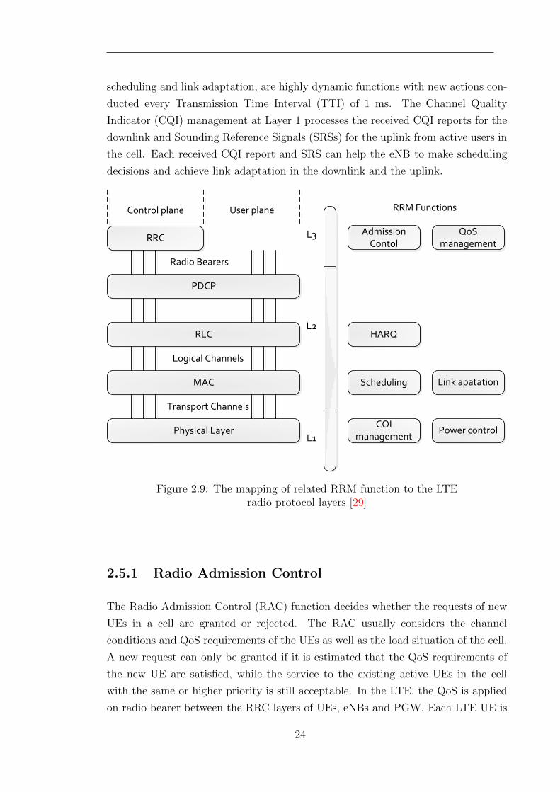
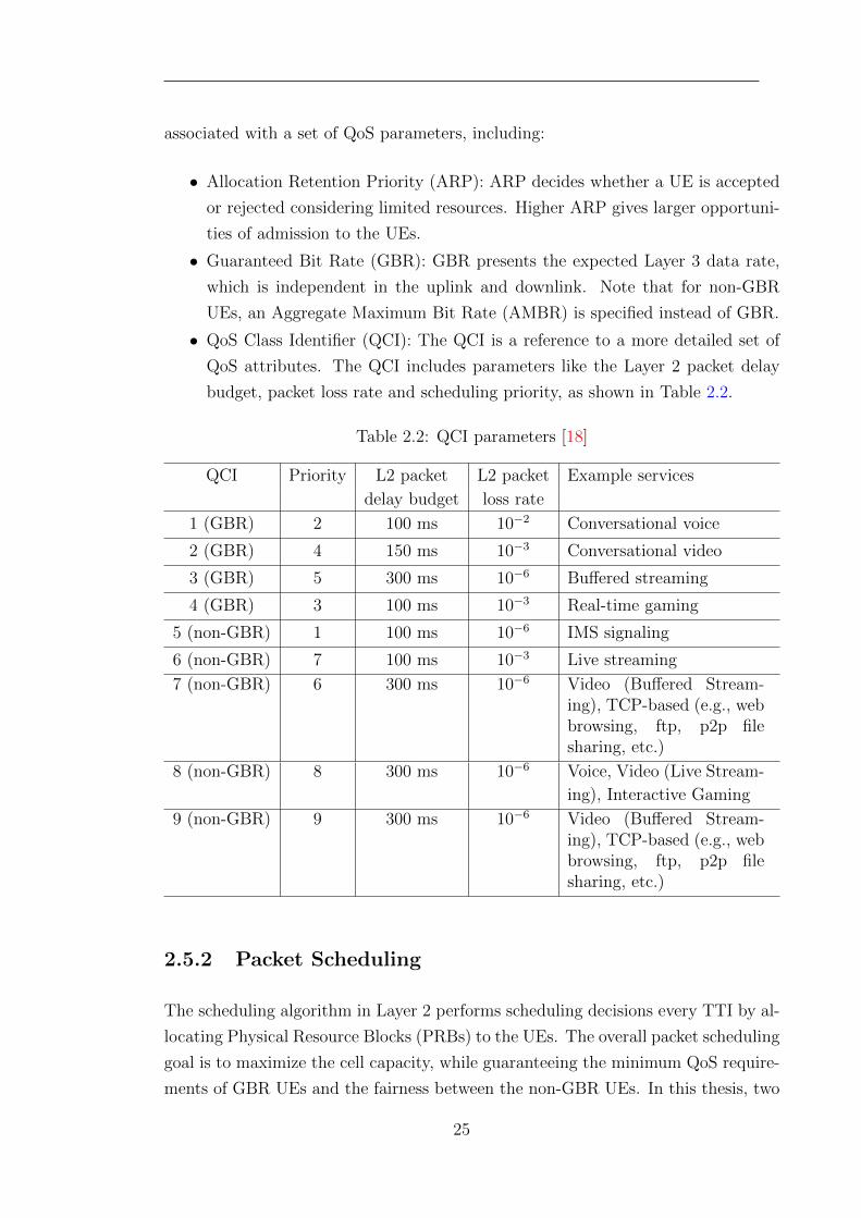
• QoS Class Identifier (QCI): The QCI is a reference to a more detailed set of
QoS attributes. The QCI includes parameters like the Layer 2 packet delay
budget, packet loss rate and scheduling priority, as shown in Table 2.2.
Table 2.2: QCI parameters [18]
QCI Priority L2 packet L2 packet Example services
delay budget loss rate
1 (GBR) 2 100 ms 10−2 Conversational voice
2 (GBR) 4 150 ms 10−3 Conversational video
3 (GBR) 5 300 ms 10−6 Buffered streaming
4 (GBR) 3 100 ms 10−3 Real-time gaming
5 (non-GBR) 1 100 ms 10−6 IMS signaling
6 (non-GBR) 7 100 ms 10−3 Live streaming
7 (non-GBR) 6 300 ms 10−6 Video (Buffered Stream-ing), TCP-based (e.g., webbrowsing, ftp, p2p filesharing, etc.)
8 (non-GBR) 8 300 ms 10−6 Voice, Video (Live Stream-
ing), Interactive Gaming
9 (non-GBR) 9 300 ms 10−6 Video (Buffered Stream-ing), TCP-based (e.g., webbrowsing, ftp, p2p filesharing, etc.)
2.5.2 Packet Scheduling
The scheduling algorithm in Layer 2 performs scheduling decisions every TTI by al-
locating Physical Resource Blocks (PRBs) to the UEs. The overall packet scheduling
goal is to maximize the cell capacity, while guaranteeing the minimum QoS require-
ments of GBR UEs and the fairness between the non-GBR UEs. In this thesis, two
25
scheduling algorithms, Round-Robin (RR) and Proportional Fair (PF), are consid-
ered.
As the Round-Robin (RR) algorithm is used, the PRBs are assigned to the UEs
in equal portions and in circular order. There is no priority for the UEs, and there
is no need to acquire the channel condition information of the UEs. Therefore, the
RR algorithm is simple and easy to implement. In some cases, the RR algorithm
can be extended to the weighted RR algorithm [30], which is considered in Chapter
3.
The Proportional Fair (PF) scheduling algorithm is aimed at achieving an ef-
fective compromise between throughput and fairness. This algorithm is performed
by giving each UE a priority that is proportional to its instantaneous data rate,
and inversely proportional to its past average data rate. According to [17, 31], the
resources can be fairly allocated to the UEs, and a scheduling gain compared with
the RR algorithm can be obtained.
In these two scheduling algorithms, each UE can get equal portion of Physical
Resource Blocks (PRBs), which is important to the fairness between the UEs. Each
allocated PRB should select an appropriate Modulation and Coding Scheme (MCS)
according to the channel condition. This is called Adaptive Modulation and Coding
(AMC) scheme used for link adaptation. The PRB allocation information and the
selected MCS are acknowledged by the scheduled UEs through the control channels.
2.5.3 Link Adaptation
Link adaptation is used to determine the data rate carried in each sub-carrier based
on the MCS. AMC is adopted by the link adaptation in the LTE. AMC primarily
makes its decisions according to the CQI feedback from the UEs. LTE supports fast
adaptive link adaptation performed on a millisecond basis. The mapping from the
CQI to the MCS is illustrated in Table 2.3.
2.5.4 Power Control
In LTE, slow power control is used for the uplink transmission, and there is no power
control in the downlink transmission [32].
The main purpose of the power control in the LTE uplink is to reduce the energy
26
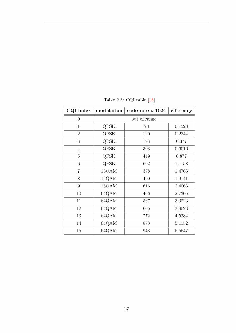
Table 2.3: CQI table [18]
CQI index modulation code rate x 1024 efficiency
0 out of range
1 QPSK 78 0.1523
2 QPSK 120 0.2344
3 QPSK 193 0.377
4 QPSK 308 0.6016
5 QPSK 449 0.877
6 QPSK 602 1.1758
7 16QAM 378 1.4766
8 16QAM 490 1.9141
9 16QAM 616 2.4063
10 64QAM 466 2.7305
11 64QAM 567 3.3223
12 64QAM 666 3.9023
13 64QAM 772 4.5234
14 64QAM 873 5.1152
15 64QAM 948 5.5547
27
consumption of mobile devices and avoid unbalanced uplink coverage of the eNBs.
A closed loop fractional uplink power control method is applied in LTE. In order
to maximise the desired received power while limiting the generated interference,
the transmitting power of UE is based on fractional path loss (PL) compensation,
which is defined in [32]:
P = min{ Pmax, P0 + 10 log10(N) + αPL} (2.1)
where Pmax is the maximum transmitting power of a UE, α and P0 are the path loss
compensation factor and a parameter to ensure the minimum received signal power
level, and N is the number of uplink PRBs allocated to the UE.
In the LTE downlink, the total transmitting power of eNBs will not change
according to the channel conditions. Nonetheless, the eNBs can decide the energy
distributed on each sub-carrier, which is called power allocation. The power in some
sub-carriers can also be eliminated or reduced to achieve Inter-Cell Interference
Coordination (ICIC) [33].
2.6 LTE-Advanced
Nonetheless, the LTE is not a real 4G network as in the commercial advertisements,
because it does not fulfil the requirements of the 4G specifications, International
Mobile Telecommunication (IMT) Advanced [12], defined by the ITU. In addition,
cell-edge performance of the LTE should also be improved. Hence in September
2009, the 3GPP Partners made a formal submission to the ITU to propose LTE Re-
lease 10 and beyond (LTE-Advanced) be evaluated as a candidate of IMT-Advanced
[13]. The requirements of LTE-Advanced are naturally decided to achieve or even
enhance IMT-Advanced requirements. Peak data rates of up to 1 Gbits/s in the
downlink and 500 Mbits/s in the uplink, and scalable bandwidth up to 100 MHz
are expected. Lower user and control plane latencies, larger VoIP capacity and
better cell-edge performance are also anticipated. These requirements will enable
LTE-Advanced to address increasing user requirements. Accordingly, the main is-
sue in LTE-Advanced is to develop new technologies allowing LTE-Advanced to
meet the proposed targets. Several techniques have been proposed and confirmed
in Release 10 [14, 15], including spectrum aggregation, relaying and Coordinated
Multi-Point (CoMP) transmission and reception. Other important requirements of
LTE-Advanced also include backward compatibility and spectrum flexibility [16].
28
Hence, LTE-Advanced should be considered as an evolution rather than a revolu-
tion from LTE with better system performance, different structure and less cost.
Relaying technology is expected to promote the cell-edge performance. Thus, the
LTE-Advanced networks with relays is the research area of concern in this thesis.
2.6.1 Network Architecture with Relay
As the cell edge performance becomes more critical to LTE-Advanced networks,
relaying technology is proposed to alleviate the performance degradation at the cell
edge. The cell-edge performance degradation is caused by low signal strength and
high interference levels. The idea of relaying is not new, which has been applied in
microwave communication and Ad hoc networks. Nonetheless, the use of relaying
in LTE-Advanced is different from those in other networks. LTE-Advanced uses a
fixed relay infrastructure without a wired backhaul connection, and the messages
between the eNB and UEs go through no more than two hops.
The relay node (RN) is connected to a donor cell of a donor eNB via the wireless
Un interface, and the UE connects to the RN via the Uu interface [24], which is
shown in Fig. 2.10 . The link between the eNB and the RN is usually called the
backhaul link, and the link between the RN and the UE is the access link. The link
between the eNB and the UE is commonly named the direct link.
2.6.2 Types of Relay Nodes
Relay nodes (RNs) in LTE-Advanced have several different classifications according
to different criteria.
Amplify-and-Forward v.s. Decode-and-Forward RNs
In the Amplify-and-Forward (AF) relaying scheme, the transmitted data is received
and amplified by the RNs. There are less computation and delay with this scheme.
However, the interference and the thermal noise at the RNs are also amplified.
In the Decode-and-Forward (DF) relaying scheme, the RNs decode the received
signal from the eNB and transmit the encoded data to the destination UEs in the
downlink. Better channel conditions of the two-hop transmission can be obtained.
29
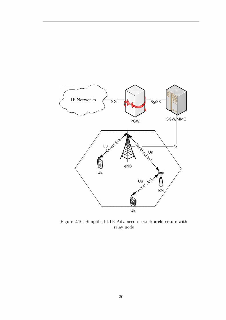
S1
UE
UE
Uu
IP Networks
PGW SGW/MME
SGi S5/S8
eNB
RN
Backhaul link
Direct li
nk
Access link
Un
Uu
Figure 2.10: Simplified LTE-Advanced network architecture withrelay node
30
Since the RN buffer is finite, all the data received from the eNB should be trans-
mitted to the UEs to avoid resource waste.
L1, L2 and L3 RNs
From the perspective of the protocol architecture of relaying, L1, L2 and L3 RNs are
specified in [34]. The L1 RN just amplifies the signal from eNB/UE and forwards it
to the UE/eNB. The L2 RN performs the scheduling function. The resource alloca-
tion between the UE and the L2 RN is performed in coordination with eNB and the
other L2 RNs, taking inter-cell interference and load conditions into consideration.
The L3 RN has partial or full functions of RRC resided in eNB. The latency due to
the handover and fast data routing can be reduced. The L3 measurements may be
utilised for handover decisions in the RNs.
In-band v.s. Out-band RNs
With respect to the usage of spectrum, the operation of RNs can be classified into
in-band and out-band. The eNB-RN links of the out-band RNs are not allowed to
operate on the same carrier frequency band as RN-UE links; the in-band RNs can
operate the eNB-RN links and the RN-UE links on the same carrier frequency band,
which can reduce the complexity of frequency band planning. In addition, for both
in-band and out-band relaying, it is possible to operate the eNB-RN link on the
same carrier frequency band as eNB-to-UE links.
Transparent v.s. Non-transparent RNs
In relation to the information for UEs, RNs can be classified into transparent and
non-transparent, according to whether the UEs are aware of their associating RN
or not. The transparent RNs will not extend the coverage, but is beneficial for
cooperative communication. The non-transparent RNs have cell IDs and can provide
some RRM functions.
Type 1 and Type 2 RNs
In the LTE-Advanced standards [14], Type 1 and Type 2 RNs are defined with the
following characteristics:
31
• A basic Type 1 RN is an in-band relay node with the following characteristics:
– It controls a cell, and appears to a UE as a separate cell different from
the donor cell;
– The cells controlled by the RNs shall have their own physical cell Iden-
tifier (ID), defined in LTE Rel-8, and the RNs shall transmit their own
synchronization channels, reference symbols and so on;
– In the context of single-cell operation, scheduling and HARQ functions
can be conducted by the RN. The control channels also exist at the RNs;
– It shall appear as a special UE to the eNB.
• Type 1a and Type 1b RNs are characterised by the same set of features as the
basic Type 1 RN described above, except that the Type 1a RN operates out-
band and the Type 1b RN operates in-band with adequate antenna isolation.
A basic Type 1 RN is expected to have little or no impact on LTE Release-8
specifications.
• A Type 2 relay node is an in-band relay node with the following characteristics:
– It does not have a separate Physical Cell ID and thus would not create
any new cells;
– It is transparent to Rel-8 UEs; a Rel-8 UE is not aware of the presence
of a Type 2 relay node;
– It can transmit Physical Downlink Shared Channel (PDSCH) as the data
channel;
– At least, it does not transmit Common Reference Signal (CRS) and Phys-
ical Downlink Control Channel (PDCCH) for control functionalities.
Depending on different types of RNs, a RN may be part of the donor cell or
controls a cell of its own. In the case that the RN is part of the donor cell, it does
not have a cell identity of its own, but still has a relay ID. Most of RRM functions
are executed by the eNB of the donor cell, and few parts of the RRM functions
may be located in the RN. In the case that a RN is in control of a cell of its own,
a unique physical layer cell ID is provided in its cell. The same RRM mechanisms
as the eNB are available at the RNs. There is no significant difference between
accessing cells controlled by a RN and connecting cells controlled by a normal eNB
from the perspective of the RRM of a UE. The cells controlled by the RNs should
support also LTE Rel-8 UEs.
32
Among the above types of relay nodes in LTE-Advanced, basic Type 1 decode-
and-forward in-band non-transparent half-duplex fixed RNs are considered as the
research objective in this thesis.
2.6.3 Resource Partitioning for Relay Backhauling
Due to the transmitter of RN causing interference to its own receiver, simultaneous
eNB-to-RN and RN-to-UE transmissions on the same time-frequency resource units
may not be feasible, unless sufficient isolation of the outgoing and incoming signals
is provided. Similarly, at the RN, it may not be possible to receive UE transmissions
simultaneously with the RN transmitting to the eNB.
In order to accommodate Type 1 RNs, [4] defines a general principle for resource
partitioning at the RN as follows:
• eNB→RN and RN→UE links are time division multiplexed in a single carrier
frequency (only one is active at any time)
• RN→eNB and UE→RN links are time division multiplexed in a single carrier
frequency (only one is active at any time)
The backhaul links, i.e. eNB→RN and RN→eNB transmissions, are done in the
downlink frequency band and the uplink frequency band respectively in the FDD
mode. In the TDD frames, the backhaul links are in the downlink subframes of the
eNB and the uplink subframes of the RN separately.
Considering backward compatibility with 3GPP Rel-8 LTE, the RN is not per-
mitted to transmit to UEs when it is supposed to receive data from the donor eNB,
i.e. to create gaps in the RN-to-UE transmission. In these gaps, the UEs associat-
ing with the RN are not supposed to expect any transmission from the RN. These
gaps can be created by configuring Multimedia Broadcast multicast service Single
Frequency Network (MBSFN) subframes as exemplified in Fig. 2.11. RN-to-eNB
transmissions can be facilitated by not allowing any UE-to-RN transmissions in some
subframes.
33
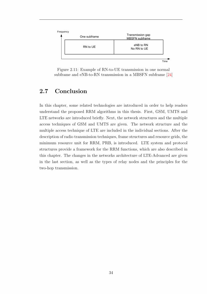
Time
Frequency
Figure 2.11: Example of RN-to-UE transmission in one normalsubframe and eNB-to-RN transmission in a MBSFN subframe [24]
2.7 Conclusion
In this chapter, some related technologies are introduced in order to help readers
understand the proposed RRM algorithms in this thesis. First, GSM, UMTS and
LTE networks are introduced briefly. Next, the network structures and the multiple
access techniques of GSM and UMTS are given. The network structure and the
multiple access technique of LTE are included in the individual sections. After the
description of radio transmission techniques, frame structures and resource grids, the
minimum resource unit for RRM, PRB, is introduced. LTE system and protocol
structures provide a framework for the RRM functions, which are also described in
this chapter. The changes in the networks architecture of LTE-Advanced are given
in the last section, as well as the types of relay nodes and the principles for the
two-hop transmission.
34
Chapter 3
Service-Aware Adaptive
Bidirectional Optimisation Route
Selection
3.1 Introduction
Due to a great degree of difference between the transmitting power of an eNB and a
RN, uplink performance and downlink performance sometimes cannot be optimised
simultaneously. As an important aspect of RRM, the conventional route selection
strategies optimise either downlink performance only or uplink performance only.
However, the UEs launching different types of services have different requirements
in the uplink and the downlink. By being aware of service type, an Adaptive Bidi-
rectional Optimisation (ABO) route selection strategy is proposed in this chapter to
optimise uplink performance and downlink performance adaptively and dynamically.
The objective of the proposed ABO strategy is to maximise the UE bidirectional
throughput, which is the sum throughput of uplink and downlink. Moreover, load
balancing is considered in the formulation of the proposed strategy to be adapted
to different fixed resource partitioning schemes. Through system-level simulation,
it can be seen that the proposed strategy is better than the benchmark strategies
in different frame configurations.
In this chapter, the related work to this study is reviewed first. After present-
ing the system models and assumptions, the problem of bidirectional optimisation
route selection is formulated and analysed. Then, the proposed ABO route selection
35
strategy is described together with a complexity analysis. Finally, the simulation re-
sults demonstrate the performance advantages of the proposed ABO route selection
strategy.
3.2 Related work
[35] proposes a distributed Load Balancing Relay Selection (LB-RS) scheme for
relay enhanced OFDMA networks. By considering the current CSI and the relay
user number, the proposed LB-RS scheme adopts the ratio of the current data rate
to the user number plus 1 as the selection criterion.
In [36], the two-hop achievable efficiency is considered as the harmonic mean of
the separate efficiency of backhaul links and access links. Besides, an utility function
based on the demand of the relay users and the efficiency of the relay nodes is taken
into account. Although this research is based on the MIMO channel and multiple
relay cooperative transmission, it can be extended to the non-cooperative scenario.
By using the proposed utility function in the relay selection strategy, both the QoS
requirement and the effects of the relay nodes are considered.
In [37], the relay selection algorithm allows users to select a relay node with less
load and larger instantaneous data rate. Less load of the relay node expects less
handover and delay. The load factor of the relay node is defined as the available
resource number divided by the subscribed relay users. The two-hop data rate is
the harmonic mean of the data rates of backhaul and access links respectively. The
load factor and the two-hop data rate are combined by two normalised weights.
In [38], an admission control algorithm with dynamic resource sharing in the
backhaul subframes is proposed. The users are connected to the serving nodes with
largest received signal power. When the new traffic is launched, the required PRB
number for the guaranteed data rate is estimated. If the available resources of the
connected serving node is not enough to satisfy the PRB requirement of the new
traffic, the traffic is denied.
Due to different transmitting power between relay nodes and eNBs, the relay
nodes can provide wider coverage of uplink performance gain and smaller downlink
gain coverage. In order to balance the uplink/downlink gain, a cell selection method
called ’Range Expand’ is investigated in [39] and [40]. In [39], the results show
that with larger range extension offset, the downlink performance is degrading and
36
the uplink performance is improving; when the range extension offset is 6 dB, the
bidirectional performance is optimised. With full frequency reuse and ideal backhaul
link, [40] presents that 5-tile worst throughput can be increased in downlink with
the bias of up to 4 dB and in uplink with the bias of up to 12 dB. The 5-tile worst
throughput indicates the 5th percentile of the ascending throughputs. The method
of ’Range Expansion’ is proposed to the 3GPP[41, 42]. In this method, a 9 dB bias is
added to the received signal power level from the Relay Nodes, which is considered
as the route selection metric. Hence, the coverage of RNs can be expanded. In
[43, 44], the inter-cell interference coordination schemes are proposed for the ’Range
Expansion’ route selection strategy in order to obtain better performance.
In [45], a weighted energy consumption per bit is used as the selection criteria,
which considers data rate requirement in both downlink and uplink. However, the
throughputs in the uplink and downlink under different load conditions are not
considered.
Two route selection strategies based on Signal to Interference plus Noise Ratio
(SINR) are proposed in [46]. In the first strategy, all the relay nodes and the donor
eNB in the same sector are reusing the resources in the access subframes. In the
second strategy, the resources in the access subframes are partitioned for the direct
links and access links according to the ratio of direct users and relay users. Only
the relay nodes are reusing the resources.
The traffic throughput balance between direct users and relay users is considered
in [47]. In the proposed route selection strategy, the average throughputs of the
direct and relay users are calculated respectively, and then either the direct users
with the minimum SINR in the direct link or the relay users with the minimum
SINR in the access link is changed to be relay users and direct users in order to
approach the critical point of throughput balancing.
In [48], the spectral efficiency of a two-hop link is analysed for DF half duplex
relaying. Assuming that all the relay nodes are reusing the same resources, the
two-hop spectral efficiency is the harmonic mean of the backhaul spectral efficiency
and the reuse factor times of average access spectral efficiency. It is also pointed out
in this paper that with the increasing reuse factor, the two-hop spectral efficiency
will not increase linearly since the inter-relay interference is rising.
[49] provides an early research on route selection and interference coordination.
An interference coordination based fractal frequency reuse scheme is proposed. In
any macro cell, all the relays cannot reuse the resources of the donor eNB, however
37
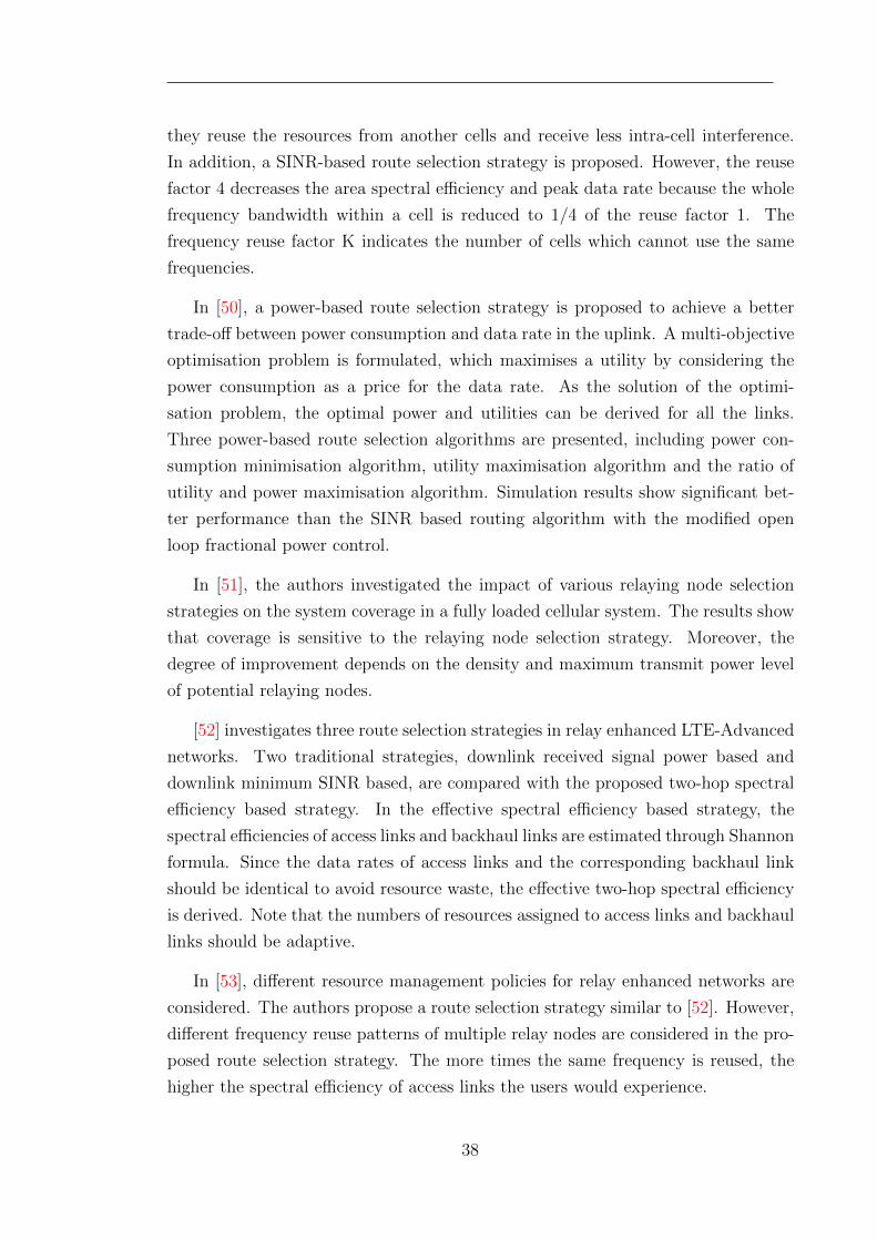
they reuse the resources from another cells and receive less intra-cell interference.
In addition, a SINR-based route selection strategy is proposed. However, the reuse
factor 4 decreases the area spectral efficiency and peak data rate because the whole
frequency bandwidth within a cell is reduced to 1/4 of the reuse factor 1. The
frequency reuse factor K indicates the number of cells which cannot use the same
frequencies.
In [50], a power-based route selection strategy is proposed to achieve a better
trade-off between power consumption and data rate in the uplink. A multi-objective
optimisation problem is formulated, which maximises a utility by considering the
power consumption as a price for the data rate. As the solution of the optimi-
sation problem, the optimal power and utilities can be derived for all the links.
Three power-based route selection algorithms are presented, including power con-
sumption minimisation algorithm, utility maximisation algorithm and the ratio of
utility and power maximisation algorithm. Simulation results show significant bet-
ter performance than the SINR based routing algorithm with the modified open
loop fractional power control.
In [51], the authors investigated the impact of various relaying node selection
strategies on the system coverage in a fully loaded cellular system. The results show
that coverage is sensitive to the relaying node selection strategy. Moreover, the
degree of improvement depends on the density and maximum transmit power level
of potential relaying nodes.
[52] investigates three route selection strategies in relay enhanced LTE-Advanced
networks. Two traditional strategies, downlink received signal power based and
downlink minimum SINR based, are compared with the proposed two-hop spectral
efficiency based strategy. In the effective spectral efficiency based strategy, the
spectral efficiencies of access links and backhaul links are estimated through Shannon
formula. Since the data rates of access links and the corresponding backhaul link
should be identical to avoid resource waste, the effective two-hop spectral efficiency
is derived. Note that the numbers of resources assigned to access links and backhaul
links should be adaptive.
In [53], different resource management policies for relay enhanced networks are
considered. The authors propose a route selection strategy similar to [52]. However,
different frequency reuse patterns of multiple relay nodes are considered in the pro-
posed route selection strategy. The more times the same frequency is reused, the
higher the spectral efficiency of access links the users would experience.
38
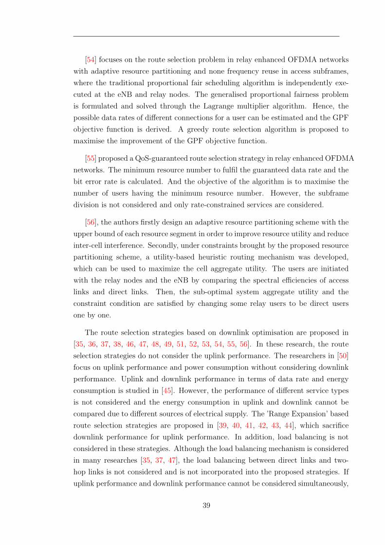
[54] focuses on the route selection problem in relay enhanced OFDMA networks
with adaptive resource partitioning and none frequency reuse in access subframes,
where the traditional proportional fair scheduling algorithm is independently exe-
cuted at the eNB and relay nodes. The generalised proportional fairness problem
is formulated and solved through the Lagrange multiplier algorithm. Hence, the
possible data rates of different connections for a user can be estimated and the GPF
objective function is derived. A greedy route selection algorithm is proposed to
maximise the improvement of the GPF objective function.
[55] proposed a QoS-guaranteed route selection strategy in relay enhanced OFDMA
networks. The minimum resource number to fulfil the guaranteed data rate and the
bit error rate is calculated. And the objective of the algorithm is to maximise the
number of users having the minimum resource number. However, the subframe
division is not considered and only rate-constrained services are considered.
[56], the authors firstly design an adaptive resource partitioning scheme with the
upper bound of each resource segment in order to improve resource utility and reduce
inter-cell interference. Secondly, under constraints brought by the proposed resource
partitioning scheme, a utility-based heuristic routing mechanism was developed,
which can be used to maximize the cell aggregate utility. The users are initiated
with the relay nodes and the eNB by comparing the spectral efficiencies of access
links and direct links. Then, the sub-optimal system aggregate utility and the
constraint condition are satisfied by changing some relay users to be direct users
one by one.
The route selection strategies based on downlink optimisation are proposed in
[35, 36, 37, 38, 46, 47, 48, 49, 51, 52, 53, 54, 55, 56]. In these research, the route
selection strategies do not consider the uplink performance. The researchers in [50]
focus on uplink performance and power consumption without considering downlink
performance. Uplink and downlink performance in terms of data rate and energy
consumption is studied in [45]. However, the performance of different service types
is not considered and the energy consumption in uplink and downlink cannot be
compared due to different sources of electrical supply. The ’Range Expansion’ based
route selection strategies are proposed in [39, 40, 41, 42, 43, 44], which sacrifice
downlink performance for uplink performance. In addition, load balancing is not
considered in these strategies. Although the load balancing mechanism is considered
in many researches [35, 37, 47], the load balancing between direct links and two-
hop links is not considered and is not incorporated into the proposed strategies. If
uplink performance and downlink performance cannot be considered simultaneously,
39
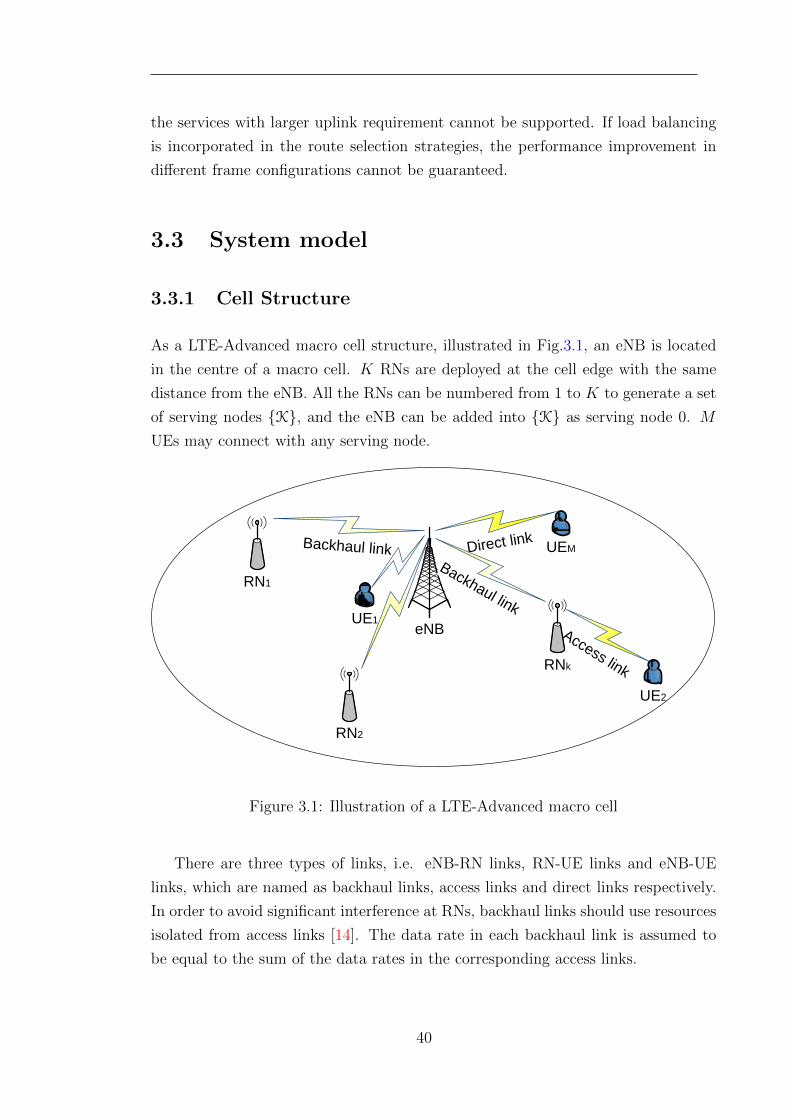
the services with larger uplink requirement cannot be supported. If load balancing
is incorporated in the route selection strategies, the performance improvement in
different frame configurations cannot be guaranteed.
3.3 System model
3.3.1 Cell Structure
As a LTE-Advanced macro cell structure, illustrated in Fig.3.1, an eNB is located
in the centre of a macro cell. K RNs are deployed at the cell edge with the same
distance from the eNB. All the RNs can be numbered from 1 to K to generate a set
of serving nodes {K}, and the eNB can be added into {K} as serving node 0. M
UEs may connect with any serving node.
eNBUE1
Backhaul link Direct link
Access linkRNk
Backhaul link
RN1
UE2
RN2
UEM
Figure 3.1: Illustration of a LTE-Advanced macro cell
There are three types of links, i.e. eNB-RN links, RN-UE links and eNB-UE
links, which are named as backhaul links, access links and direct links respectively.
In order to avoid significant interference at RNs, backhaul links should use resources
isolated from access links [14]. The data rate in each backhaul link is assumed to
be equal to the sum of the data rates in the corresponding access links.
40
3.3.2 Radio Transmission Model
In LTE-Advanced uplink and downlink, different time slots and different amount of
resources are assigned to different links according to different frame configurations.
In these frame configurations, the direct links and the access links are reusing all the
resources assigned to them. For the multi-cell scenario, the cells adjacent to each
other are using the same carrier frequency band since the inter-cell interference can
be alleviated by employing RNs.
Physical resource block (PRB) is a basic OFDM resource allocation unit, which
comprises of a constant number of subcarriers and OFDM symbols [22]. All the
serving nodes and the UEs are assumed to allocate the same power over every
occupied PRB, and the sum of the transmitting power in all occupied PRBs should
not exceed the maximum power. In addition, fractional uplink power control is
applied in UEs. In order to maximise the desired received power while limiting the
generated interference, the transmitting power of a UE is based on fractional path
loss (PL) compensation, which is defined in [32]:
P = min{ Pmax, P0 + 10 log10(N) + αPL} (3.1)
where Pmax is the maximum transmitting power of a UE, α and P0 are the path loss
compensation factor and a parameter to ensure the minimum received signal power
level, and N is the number of uplink PRBs allocated to that UE.
In order to estimate the achievable data rate, we consider a long term Signal to
Interference plus Noise Ratio (SINR) which is a average value of past instantaneous
SINRs obtained through channel measurements. Hence, the long term SINR is
updated in periodically with a reasonable moving filter to alleviate the effect of fast
fading. The durations are different considering different UE movement speeds. A
transmission between UE m and serving node k has different SINR values in different
assigned PRBs.
To simplify the analysis, three service types with different uplink and downlink
requirements, i.e. QUL and QDL, are defined in this study, including uplink-biased
service, downlink-biased service and symmetric service. One UE can only launch one
type of service at one time. QUL and QDL are defined as the maximum PRB numbers
which can be scheduled to the services in the uplink and the downlink respectively.
They prevent the data rates of the UEs in the top channel from exceeding the
Maximum Bite Rate (MBR) under the constraint of fair allocation. These two
41
parameters and the MBR can be determined from the QoS class identifier (QCI)
which is assigned to each transport layer bearer by the network [57]. The QCI is used
as a reference to the eNB parameters (e.g., scheduling weights, admission thresholds,
queue management thresholds, etc.), which can be preconfigured by operators.
3.3.3 Scheduling Algorithms
Round-Robin (RR) scheduling is considered in this research to guarantee the allo-
cation fairness between UEs, which is usually considered as a benchmark scheduling
scheme. Being executed in the direct links and the access links independently,
Round-Robin scheduling assigns an equal portion of PRBs to each UE until the
maximum uplink and downlink PRB requirements, i.e. QUL and QDL, are satisfied.
When the Round-Robin scheduling scheme is applied, UE m is, statistically speak-
ing, allocated to all PRBs randomly. Thus, its data rate per PRB can be estimated
to be the average data rate of all PRBs. Through Shannon’s formula, the achievable
data rate per PRB in the transmission of the m↔ k link can be calculated as
σm,k = Blog2(1 + γm,k,i), ∀i ∈ all PRBs (3.2)
where B is the bandwidth of a PRB and γm,k,i is the large scale SINR on PRB i in
the m↔ k link.
Proportional-fair (PF) scheduling is also considered in this research to exploit
the channel variation and guarantee the allocation fairness between UEs. In the
direct links and the access links, the PF scheduling assigns each PRB to the UE m∗
with the largest ratio of the current data rate rm,k,i to the history data rate Rm
m∗ = arg maxrm,k,iRm
(3.3)
When Proportional-fair scheduling is utilised, the achievable data rate per PRB can
be simplified into a UE number related scheduling gain G multiplying the data rate
per PRB achieved by the Round-Robin scheduling [31, 58]. The achievable data rate
per PRB in the transmission of the m ↔ k link under Proportional-fair scheduling
can be calculated as
σm,k = G(k)×Blog2(1 + γm,k,i),∀i ∈ all PRBs (3.4)
The scheduling gain G(k) is different for different serving node k according to the
42
numbers of UEs being scheduled, which can be derived by off-line simulation.
3.4 Problem Formulation and Analysis
With the objective of maximising the bidirectional throughput of the UEs, the route
selection problem is formulated as
maxRm = max(RULm +RDL
m )
= max∑k∈K
ρm,k(βULm,kσ
ULm,k + βDLm,kσ
DLm,k) (3.5)
subject to ∑m∈M
ρm,kβULm,k ≤ BWUL
k ,∀k ∈ K (3.6)
∑m∈M
ρm,kβDLm,k ≤ BWDL
k ,∀k ∈ K (3.7)
k 6=0∑k∈K
∑m∈M
ρm,kβULm,kσ
ULm,k
σULk,0≤ BWUL
K,0 (3.8)
k 6=0∑k∈K
∑m∈M
ρm,kβDLm,kσ
DLm,k
σDLk,0≤ BWDL
K,0 (3.9)
In the utility function (3.5), Rm is the bidirectional data rate achieved by UE m,
RULm and RDL
m represent its uplink and downlink data rate respectively. When UE
m is connected to serving node k, the uplink data rate and the downlink data rate
are determined by the achievable numbers of the occupied PRBs, denoted as βULm,kand βDLm,k, and the achievable data rates per PRB in these links, i.e. σULm,k and σDLm,k,
which are derived from equations (3.2) and (3.4). In addition, ρm,k is a connection
index.
ρm,k =
{1 when UE m is connected to node k
0 otherwise
∑k∈K
ρm,k = 1 (3.10)
In the constraints (3.6) and (3.7), if UE m is not associating with serving node k,
βULm,k and βDLm,k will be 0. BWULk and BWDL
k are the maximum uplink and downlink
PRB numbers in serving node k respectively according to the frame configurations
43
defined in Section 4. As shown in the expressions (3.8) and (3.9), the achievable data
rates in the access links are also constrained by the total PRB numbers assigned
to the backhaul links. BWULK,0 and BWDL
K,0 are the total uplink and downlink PRB
numbers respectively assigned to the backhaul links. σULk,0 and σDLk,0 indicate the data
rates per PRB in these backhaul links.
Using fair-based resource scheduling algorithms, e.g. Round-Robin and Proportional-
fair, the PRBs can be assigned to each UE in equal portions. Thus, under the
constraints (3.6)-(3.9), βULm,k and βDLm,k can be calculated as follows:
• for a direct link between UE m and the macro eNB
βULm,0 = min(QULm , bQUL
m
BWUL0∑
m∈M ρm,0QULm
c) (3.11)
βDLm,0 = min(QDLm , bQDL
m
BWDL0∑
m∈M ρm,0QDLm
c) (3.12)
• for a relay link via a RN, serving node k, where k ∈ K and k 6= 0
βULm,k = min(QULm , bQUL
m
BWULk∑
m∈M ρm,kQULm
c,
bQULm
BWULK,0∑k 6=0
k∈K∑
m∈M ρm,kQULm σULm,k/σ
ULk,0
c) (3.13)
βDLm,k = min(QDLm , bQDL
m
BWDLk∑
m∈M ρm,kQDLm
c,
bQDLm
BWDLK,0∑k 6=0
k∈K∑
m∈M ρm,kQDLm σDLm,k/σ
DLk,0
c) (3.14)
Load balancing in conventional cellular networks usually refers to distributing
traffic load among base stations, while maintaining QoS for users. In relay-enhanced
networks, load balancing is usually defined as an integral part of RRM schemes,
which is aimed at evenly distributing traffic load among all serving nodes in a macro
cell. However, there is no literature on load balancing mechanism considering both
uplink and downlink so far. Thus, a new load balancing mechanism is necessary for
the ABO route selection strategy.
According to Round-Robin and Proportional-fair scheduling algorithms and the
assumed resource allocation rules, traffic load in a link is defined as the ratio of the
44
total PRB requirements to the maximum PRB number assigned to this link. The
traffic load of the direct links and the access links are expressed as:
CLULm,k =
∑m∈M ρm,kQ
ULm
BWULk
,∀k ∈ K (3.15)
CLDLm,k =
∑m∈M ρm,kQ
DLm
BWDLk
,∀k ∈ K (3.16)
and the traffic load of the backhaul links are presented as
CLULK,0 =
k 6=0∑k∈K
∑m∈M
ρm,kQULm σULm,k
BWULK,0σ
ULk,0
,∀k ∈ K, k 6= 0 (3.17)
CLDLK,0 =
k 6=0∑k∈K
∑m∈M
ρm,kQDLm σDLm,k
BWDLK,0σ
DLk,0
,∀k ∈ K, k 6= 0 (3.18)
By substituting (3.15)-(3.18) into (3.11)-(3.14), the achievable PRB numbers of
all UEs can be expressed as:
• for a direct link between UE m and the macro eNB
βULm,0 = b QULm
max(1, CLULm,0)c (3.19)
βDLm,0 = b QDLm
max(1, CLDLm,0)c (3.20)
• for a relay link via a RN, serving node k, where k ∈ K and k 6= 0
βULm,k = b QULm
max(1, CLULm,k) max(1, CLULK,0)c (3.21)
βDLm,k = b QDLm
max(1, CLDLm,k) max(1, CLDLK,0)c (3.22)
3.5 Algorithm Description
To implement the adaptive bidirectional optimisation (ABO) route selection strat-
egy with load balancing proposed in this chapter, several channel parameters are
necessary: the data rates per PRB in each uplink and each downlink, i.e. σULm,k and
45
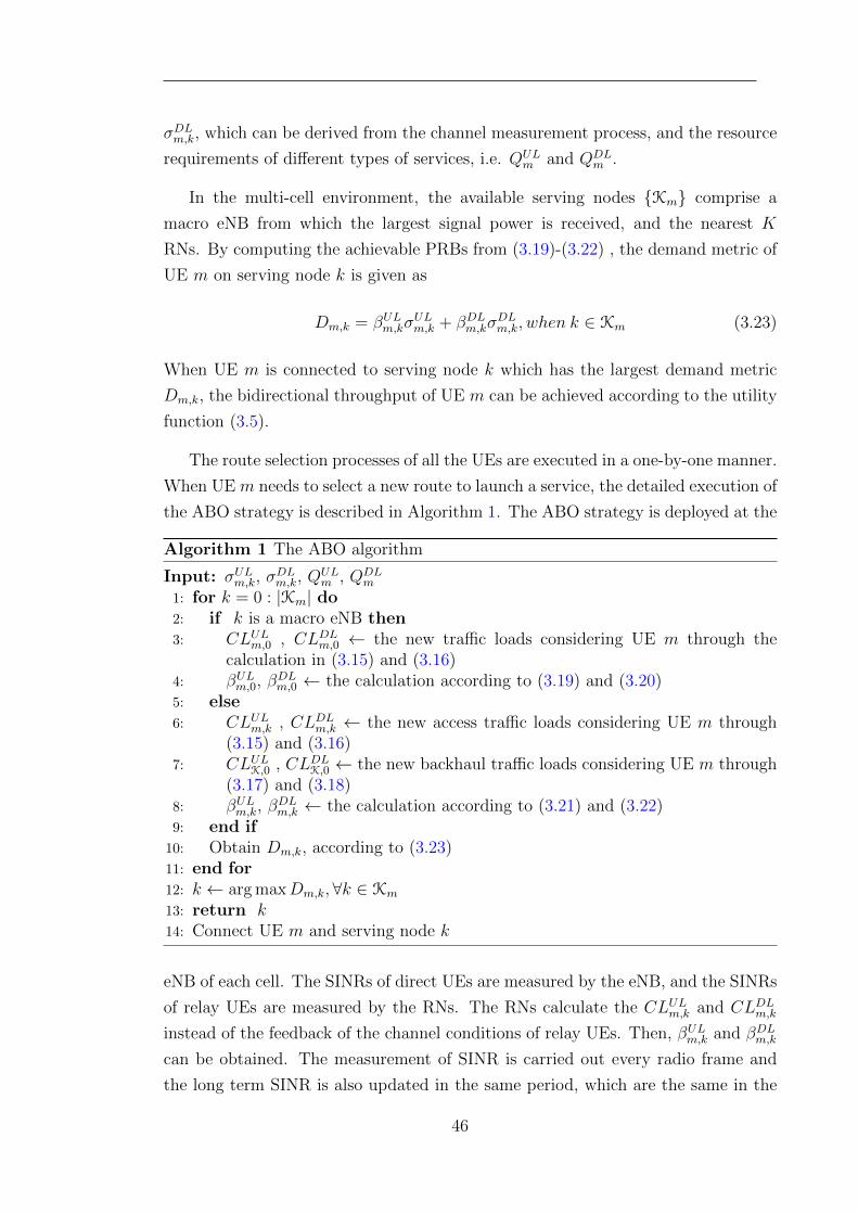
σDLm,k, which can be derived from the channel measurement process, and the resource
requirements of different types of services, i.e. QULm and QDL
m .
In the multi-cell environment, the available serving nodes {Km} comprise a
macro eNB from which the largest signal power is received, and the nearest K
RNs. By computing the achievable PRBs from (3.19)-(3.22) , the demand metric of
UE m on serving node k is given as
Dm,k = βULm,kσULm,k + βDLm,kσ
DLm,k, when k ∈ Km (3.23)
When UE m is connected to serving node k which has the largest demand metric
Dm,k, the bidirectional throughput of UE m can be achieved according to the utility
function (3.5).
The route selection processes of all the UEs are executed in a one-by-one manner.
When UE m needs to select a new route to launch a service, the detailed execution of
the ABO strategy is described in Algorithm 1. The ABO strategy is deployed at the
Algorithm 1 The ABO algorithm
Input: σULm,k, σDLm,k, Q
ULm , QDL
m
1: for k = 0 : |Km| do2: if k is a macro eNB then3: CLULm,0 , CLDLm,0 ← the new traffic loads considering UE m through the
calculation in (3.15) and (3.16)4: βULm,0, β
DLm,0 ← the calculation according to (3.19) and (3.20)
5: else6: CLULm,k , CLDLm,k ← the new access traffic loads considering UE m through
(3.15) and (3.16)7: CLULK,0 , CLDLK,0 ← the new backhaul traffic loads considering UE m through
(3.17) and (3.18)8: βULm,k, β
DLm,k ← the calculation according to (3.21) and (3.22)
9: end if10: Obtain Dm,k, according to (3.23)11: end for12: k ← arg maxDm,k,∀k ∈ Km
13: return k14: Connect UE m and serving node k
eNB of each cell. The SINRs of direct UEs are measured by the eNB, and the SINRs
of relay UEs are measured by the RNs. The RNs calculate the CLULm,k and CLDLm,kinstead of the feedback of the channel conditions of relay UEs. Then, βULm,k and βDLm,kcan be obtained. The measurement of SINR is carried out every radio frame and
the long term SINR is also updated in the same period, which are the same in the
46
existing strategies and the proposed strategy. Compared with the existing simple
route selection strategies, the frequency of SINR measurement and the messaging
between the RNs and the eNB are the same. The calculation complexity at the RNs
increases, which is within the capability of Type 1 RNs.
3.6 Complexity Analysis
In a N -cell network with K RNs per cell and overall M UEs, the calculation of all
demand metrics requires revisiting the information of UEs M times, and the deter-
mination of the largest demand metric needs N(K+1) basic operations. Hence, The
execution of the proposed strategy has a computation complexity of O(NK + M).
Compared with the existing simple route selection strategies with the complexity of
O(NK), such as Received Signal Power based strategy, the proposed ABO strategy
should acknowledge all the UEs in the network and hence increase the complexity.
However, it is quite acceptable for the practical LTE systems with the active number
of UEs not more than 120 per cell.
3.7 Performance Evaluation
3.7.1 Simulation Parameters
Based on the LTE self-evaluation methodology [14], a static system-level Matlab
simulation platform is developed to evaluate system performance using the ABO
strategy and the benchmark strategies, the Received Signal Power based (RSP)
strategy and the ”Range Expansion” (RE) strategy. This simulation platform is
extended from a open source product, Vienna LTE simulators [59], of Vienna Uni-
versity of Technology, Austria. In order to evaluate the proposed strategy, the
two-hop links are added based on the single-hop LTE simulators. Some simple sce-
narios, such as single direct UE and single relay UE at fixed positions, have been
tested to validate the simulation platform.
A seven-cell LTE-Advanced network is generated where inter-cell distance is 500
meters and 6 RNs per cell are deployed at the same distance of 2/3 of the cell
radius from the eNB. A unique number of UEs are randomly dropped in each macro
cell. A 20 MHz frequency band at 2 GHz is utilised and 100 PRBs in a time slot
47
can be used for data transmission, whilst a 10 MHz frequency band with 50 PRBs
per time slot is also considered for some performance measurements. The ”Typical
Urban Macro-cell” deployment model from 3GPP TR 36.814 [14] is employed using
lognormal shadowing with different standard deviations, 6 dB between eNB and
relay, 8 dB between eNB and macro UE and 10 dB between relay and relay UE.
The Rayleigh fast fading model is utilised to create frequency and time selective
channels. The maximum transmitting power of eNB, RN and UE is set to be 46
dBm, 30 dBm, and 23 dBm respectively. 15 dBi omni antenna is equipped in eNB,
and 5 dBi omni antenna is installed in RN, when no gain antenna is integrated
in UE. The minimum power of -56 dBm and the path loss compensation factor of
0.6 are configured in fractional uplink power control of UEs. In addition, QPSK,
16QAM and 64QAM modulation schemes are supported.The Manhattan mobility
model is considered, where the probability of going straight is 0.5 and taking a left
or right is 0.25 each. The maximum UE speed vm is assumed as 60 km/h. The
coherence time TC caused by Doppler frequency shift can be calculated according
to [60]
TC =
√9v2C
16πv2mf2c
≈ 11.4ms (3.24)
where vC is the speed of radio wave and fc is the carrier frequency, which is 2
GHz. Since the duration of a radio frame in LTE-Advanced is 10ms, the long term
average SINR is designed to be updated every radio frame using the exponential
moving average method [61]. The length of the moving average filter is set up as
100 according to [62].
Time division duplexing (TDD) LTE-Advanced is discussed in the simulations.
In a TDD LTE-Advanced radio frame, different time slots are assigned to different
links in different frame configurations, and different amount of resources are assigned
to each type of link. Two different frame configurations, Variant A and Variant B,
are considered. Inherited from the frame structure type 2 defined in [22], two frame
configurations are shown in Fig.3.2. In these two configurations, the direct links
and the access links share the same resources in some subframes, and the direct
links and the backhaul links can only use isolated resources in other subframes. In
Variant A, the direct links and the access links share subframe 2 in the uplink and
subframe 0, 3 and 4 in the downlink. In subframe 5, 7, 8 and 9, one time slot
is assigned to the direct links and the other one is orthogonally allocated to the
backhaul links according to their date rates in order to avoid serious interference
between these two types of links. In Variant B, all of subframe 7, 8, and 9 are
occupied by the backhaul links. Besides, the access link share subframe 0, 2, 3 and
48
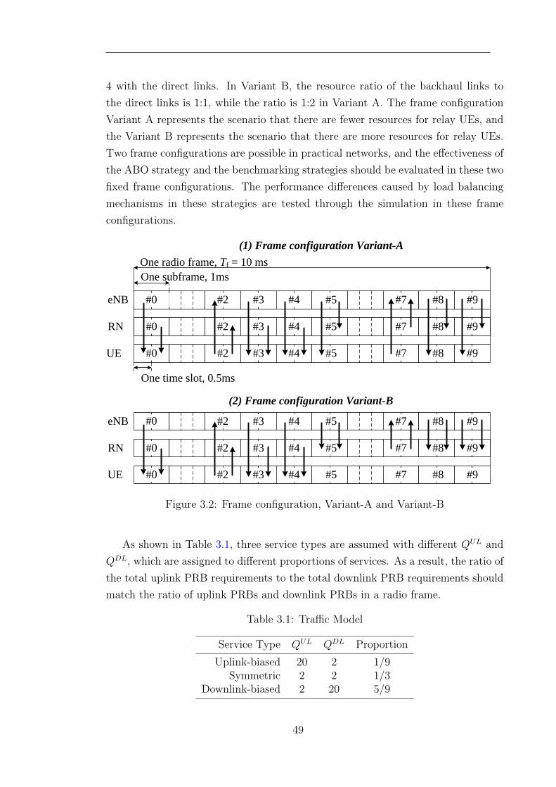
4 with the direct links. In Variant B, the resource ratio of the backhaul links to
the direct links is 1:1, while the ratio is 1:2 in Variant A. The frame configuration
Variant A represents the scenario that there are fewer resources for relay UEs, and
the Variant B represents the scenario that there are more resources for relay UEs.
Two frame configurations are possible in practical networks, and the effectiveness of
the ABO strategy and the benchmarking strategies should be evaluated in these two
fixed frame configurations. The performance differences caused by load balancing
mechanisms in these strategies are tested through the simulation in these frame
configurations.
#0 #2 #3 #4 #5 #7 #8 #9
One radio frame, Tf = 10 ms
One subframe, 1ms
One time slot, 0.5ms
#0 #2 #3 #4 #5 #7 #8 #9
#0 #2 #3 #4 #5 #7 #8 #9
eNB
RN
UE
(1) Frame configuration Variant-A
#0 #2 #3 #4 #5 #7 #8 #9
#0 #2 #3 #4 #5 #7 #8 #9
#0 #2 #3 #4 #5 #7 #8 #9
eNB
RN
UE
(2) Frame configuration Variant-B
Figure 3.2: Frame configuration, Variant-A and Variant-B
As shown in Table 3.1, three service types are assumed with different QUL and
QDL, which are assigned to different proportions of services. As a result, the ratio of
the total uplink PRB requirements to the total downlink PRB requirements should
match the ratio of uplink PRBs and downlink PRBs in a radio frame.
Table 3.1: Traffic Model
Service Type QUL QDL Proportion
Uplink-biased 20 2 1/9Symmetric 2 2 1/3
Downlink-biased 2 20 5/9
49
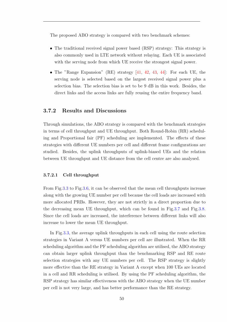
The proposed ABO strategy is compared with two benchmark schemes:
• The traditional received signal power based (RSP) strategy: This strategy is
also commonly used in LTE network without relaying. Each UE is associated
with the serving node from which UE receive the strongest signal power.
• The ”Range Expansion” (RE) strategy [41, 42, 43, 44]: For each UE, the
serving node is selected based on the largest received signal power plus a
selection bias. The selection bias is set to be 9 dB in this work. Besides, the
direct links and the access links are fully reusing the entire frequency band.
3.7.2 Results and Discussions
Through simulations, the ABO strategy is compared with the benchmark strategies
in terms of cell throughput and UE throughput. Both Round-Robin (RR) schedul-
ing and Proportional fair (PF) scheduling are implemented. The effects of these
strategies with different UE numbers per cell and different frame configurations are
studied. Besides, the uplink throughputs of uplink-biased UEs and the relation
between UE throughput and UE distance from the cell centre are also analysed.
3.7.2.1 Cell throughput
From Fig.3.3 to Fig.3.6, it can be observed that the mean cell throughputs increase
along with the growing UE number per cell because the cell loads are increased with
more allocated PRBs. However, they are not strictly in a direct proportion due to
the decreasing mean UE throughput, which can be found in Fig.3.7 and Fig.3.8.
Since the cell loads are increased, the interference between different links will also
increase to lower the mean UE throughput.
In Fig.3.3, the average uplink throughputs in each cell using the route selection
strategies in Variant A versus UE numbers per cell are illustrated. When the RR
scheduling algorithm and the PF scheduling algorithm are utilised, the ABO strategy
can obtain larger uplink throughput than the benchmarking RSP and RE route
selection strategies with any UE numbers per cell. The RSP strategy is slightly
more effective than the RE strategy in Variant A except when 100 UEs are located
in a cell and RR scheduling is utilised. By using the PF scheduling algorithm, the
RSP strategy has similar effectiveness with the ABO strategy when the UE number
per cell is not very large, and has better performance than the RE strategy.
50
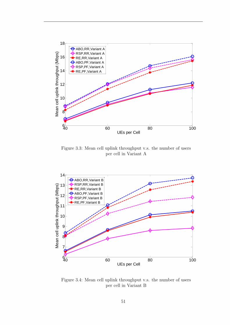
40 60 80 1006
8
10
12
14
16
18
UEs per Cell
Me
an
ce
ll u
plin
k t
hro
ug
hp
ut
(Mb
ps)
ABO,RR,Variant A
RSP,RR,Variant A
RE,RR,Variant A
ABO,PF,Variant A
RSP,PF,Variant A
RE,PF,Variant A
Figure 3.3: Mean cell uplink throughput v.s. the number of usersper cell in Variant A
40 60 80 1006
7
8
9
10
11
12
13
14
UEs per Cell
Me
an
ce
ll u
plin
k t
hro
ug
hp
ut
(Mb
ps)
ABO,RR,Variant B
RSP,RR,Variant B
RE,RR,Variant B
ABO,PF,Variant B
RSP,PF,Variant B
RE,PF,Variant B
Figure 3.4: Mean cell uplink throughput v.s. the number of usersper cell in Variant B
51
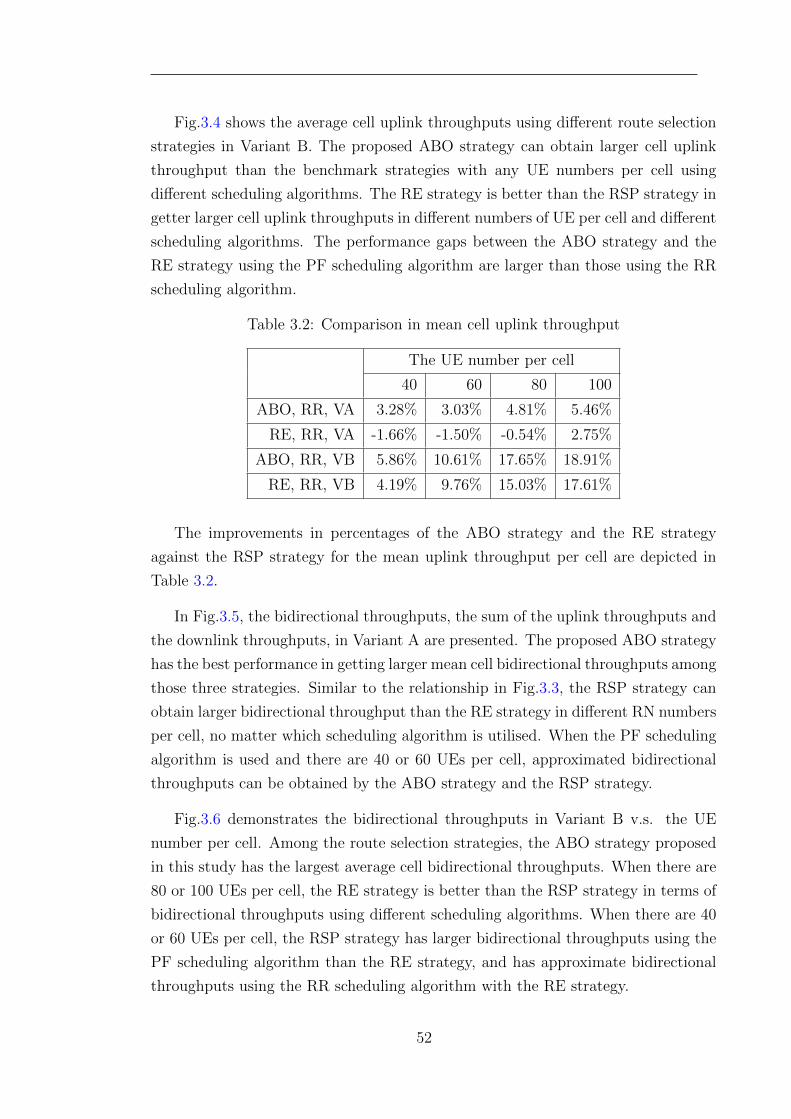
Fig.3.4 shows the average cell uplink throughputs using different route selection
strategies in Variant B. The proposed ABO strategy can obtain larger cell uplink
throughput than the benchmark strategies with any UE numbers per cell using
different scheduling algorithms. The RE strategy is better than the RSP strategy in
getter larger cell uplink throughputs in different numbers of UE per cell and different
scheduling algorithms. The performance gaps between the ABO strategy and the
RE strategy using the PF scheduling algorithm are larger than those using the RR
scheduling algorithm.
Table 3.2: Comparison in mean cell uplink throughput
The UE number per cell
40 60 80 100
ABO, RR, VA 3.28% 3.03% 4.81% 5.46%
RE, RR, VA -1.66% -1.50% -0.54% 2.75%
ABO, RR, VB 5.86% 10.61% 17.65% 18.91%
RE, RR, VB 4.19% 9.76% 15.03% 17.61%
The improvements in percentages of the ABO strategy and the RE strategy
against the RSP strategy for the mean uplink throughput per cell are depicted in
Table 3.2.
In Fig.3.5, the bidirectional throughputs, the sum of the uplink throughputs and
the downlink throughputs, in Variant A are presented. The proposed ABO strategy
has the best performance in getting larger mean cell bidirectional throughputs among
those three strategies. Similar to the relationship in Fig.3.3, the RSP strategy can
obtain larger bidirectional throughput than the RE strategy in different RN numbers
per cell, no matter which scheduling algorithm is utilised. When the PF scheduling
algorithm is used and there are 40 or 60 UEs per cell, approximated bidirectional
throughputs can be obtained by the ABO strategy and the RSP strategy.
Fig.3.6 demonstrates the bidirectional throughputs in Variant B v.s. the UE
number per cell. Among the route selection strategies, the ABO strategy proposed
in this study has the largest average cell bidirectional throughputs. When there are
80 or 100 UEs per cell, the RE strategy is better than the RSP strategy in terms of
bidirectional throughputs using different scheduling algorithms. When there are 40
or 60 UEs per cell, the RSP strategy has larger bidirectional throughputs using the
PF scheduling algorithm than the RE strategy, and has approximate bidirectional
throughputs using the RR scheduling algorithm with the RE strategy.
52
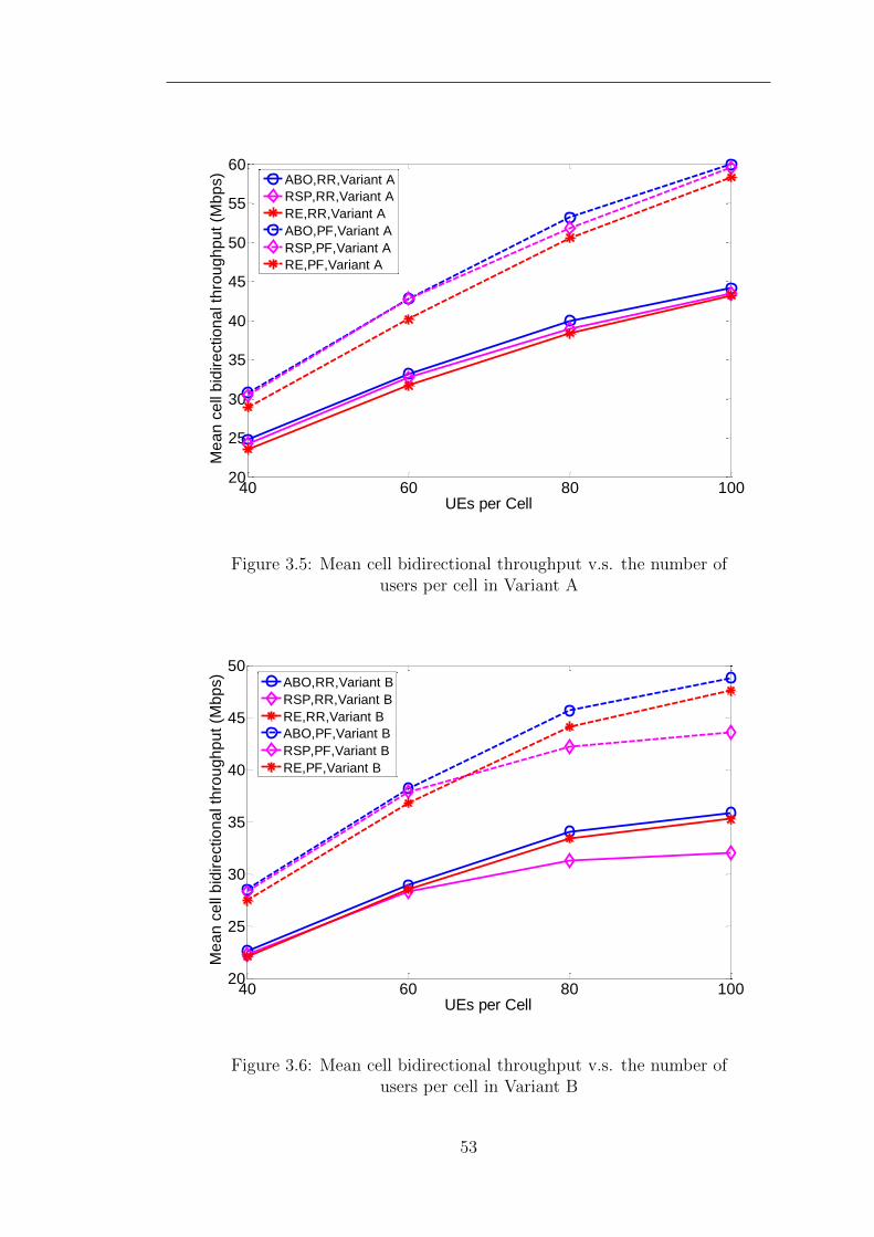
40 60 80 10020
25
30
35
40
45
50
55
60
UEs per Cell
Me
an
ce
ll b
idir
ectio
na
l th
rou
gh
pu
t (M
bp
s)
ABO,RR,Variant A
RSP,RR,Variant A
RE,RR,Variant A
ABO,PF,Variant A
RSP,PF,Variant A
RE,PF,Variant A
Figure 3.5: Mean cell bidirectional throughput v.s. the number ofusers per cell in Variant A
40 60 80 10020
25
30
35
40
45
50
UEs per Cell
Me
an
ce
ll b
idir
ectio
na
l th
rou
gh
pu
t (M
bp
s)
ABO,RR,Variant B
RSP,RR,Variant B
RE,RR,Variant B
ABO,PF,Variant B
RSP,PF,Variant B
RE,PF,Variant B
Figure 3.6: Mean cell bidirectional throughput v.s. the number ofusers per cell in Variant B
53
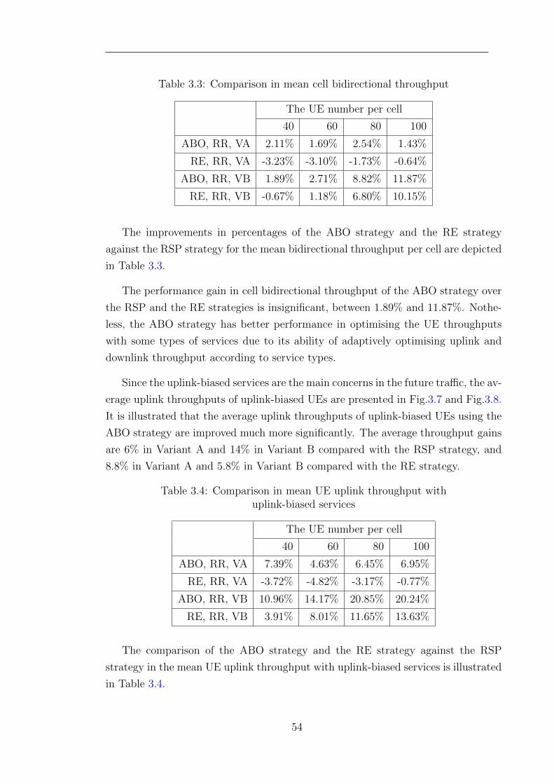
Table 3.3: Comparison in mean cell bidirectional throughput
The UE number per cell
40 60 80 100
ABO, RR, VA 2.11% 1.69% 2.54% 1.43%
RE, RR, VA -3.23% -3.10% -1.73% -0.64%
ABO, RR, VB 1.89% 2.71% 8.82% 11.87%
RE, RR, VB -0.67% 1.18% 6.80% 10.15%
The improvements in percentages of the ABO strategy and the RE strategy
against the RSP strategy for the mean bidirectional throughput per cell are depicted
in Table 3.3.
The performance gain in cell bidirectional throughput of the ABO strategy over
the RSP and the RE strategies is insignificant, between 1.89% and 11.87%. Nothe-
less, the ABO strategy has better performance in optimising the UE throughputs
with some types of services due to its ability of adaptively optimising uplink and
downlink throughput according to service types.
Since the uplink-biased services are the main concerns in the future traffic, the av-
erage uplink throughputs of uplink-biased UEs are presented in Fig.3.7 and Fig.3.8.
It is illustrated that the average uplink throughputs of uplink-biased UEs using the
ABO strategy are improved much more significantly. The average throughput gains
are 6% in Variant A and 14% in Variant B compared with the RSP strategy, and
8.8% in Variant A and 5.8% in Variant B compared with the RE strategy.
Table 3.4: Comparison in mean UE uplink throughput withuplink-biased services
The UE number per cell
40 60 80 100
ABO, RR, VA 7.39% 4.63% 6.45% 6.95%
RE, RR, VA -3.72% -4.82% -3.17% -0.77%
ABO, RR, VB 10.96% 14.17% 20.85% 20.24%
RE, RR, VB 3.91% 8.01% 11.65% 13.63%
The comparison of the ABO strategy and the RE strategy against the RSP
strategy in the mean UE uplink throughput with uplink-biased services is illustrated
in Table 3.4.
54
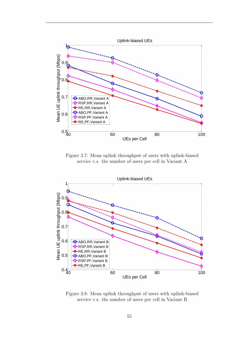
40 60 80 1000.5
0.6
0.7
0.8
0.9
1
UEs per Cell
Me
an
UE
up
link t
hro
ug
hp
ut
(Mb
ps)
Uplink-biased UEs
ABO,RR,Variant A
RSP,RR,Variant A
RE,RR,Variant A
ABO,PF,Variant A
RSP,PF,Variant A
RE,PF,Variant A
Figure 3.7: Mean uplink throughput of users with uplink-biasedservice v.s. the number of users per cell in Variant A
40 60 80 1000.4
0.5
0.6
0.7
0.8
0.9
1Uplink-biased UEs
UEs per Cell
Me
an
UE
up
link t
hro
ug
hp
ut
(Mb
ps)
ABO,RR,Variant B
RSP,RR,Variant B
RE,RR,Variant B
ABO,PF,Variant B
RSP,PF,Variant B
RE,PF,Variant B
Figure 3.8: Mean uplink throughput of users with uplink-biasedservice v.s. the number of users per cell in Variant B
55
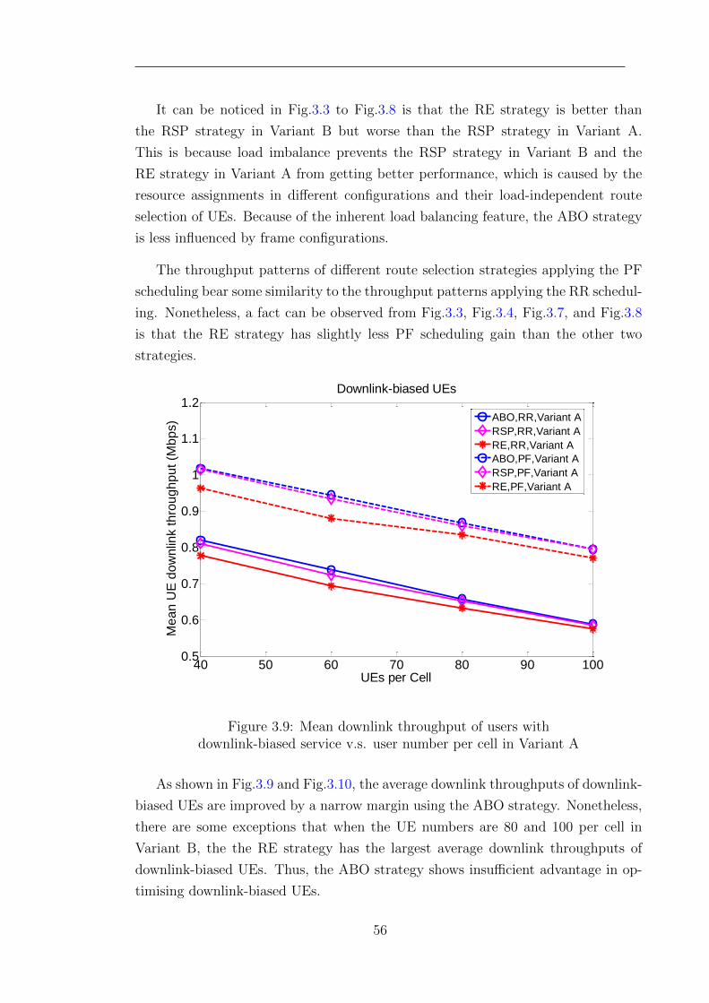
It can be noticed in Fig.3.3 to Fig.3.8 is that the RE strategy is better than
the RSP strategy in Variant B but worse than the RSP strategy in Variant A.
This is because load imbalance prevents the RSP strategy in Variant B and the
RE strategy in Variant A from getting better performance, which is caused by the
resource assignments in different configurations and their load-independent route
selection of UEs. Because of the inherent load balancing feature, the ABO strategy
is less influenced by frame configurations.
The throughput patterns of different route selection strategies applying the PF
scheduling bear some similarity to the throughput patterns applying the RR schedul-
ing. Nonetheless, a fact can be observed from Fig.3.3, Fig.3.4, Fig.3.7, and Fig.3.8
is that the RE strategy has slightly less PF scheduling gain than the other two
strategies.
40 50 60 70 80 90 1000.5
0.6
0.7
0.8
0.9
1
1.1
1.2
UEs per Cell
Me
an
UE
do
wn
link t
hro
ug
hp
ut
(Mb
ps)
Downlink-biased UEs
ABO,RR,Variant A
RSP,RR,Variant A
RE,RR,Variant A
ABO,PF,Variant A
RSP,PF,Variant A
RE,PF,Variant A
Figure 3.9: Mean downlink throughput of users withdownlink-biased service v.s. user number per cell in Variant A
As shown in Fig.3.9 and Fig.3.10, the average downlink throughputs of downlink-
biased UEs are improved by a narrow margin using the ABO strategy. Nonetheless,
there are some exceptions that when the UE numbers are 80 and 100 per cell in
Variant B, the the RE strategy has the largest average downlink throughputs of
downlink-biased UEs. Thus, the ABO strategy shows insufficient advantage in op-
timising downlink-biased UEs.
56
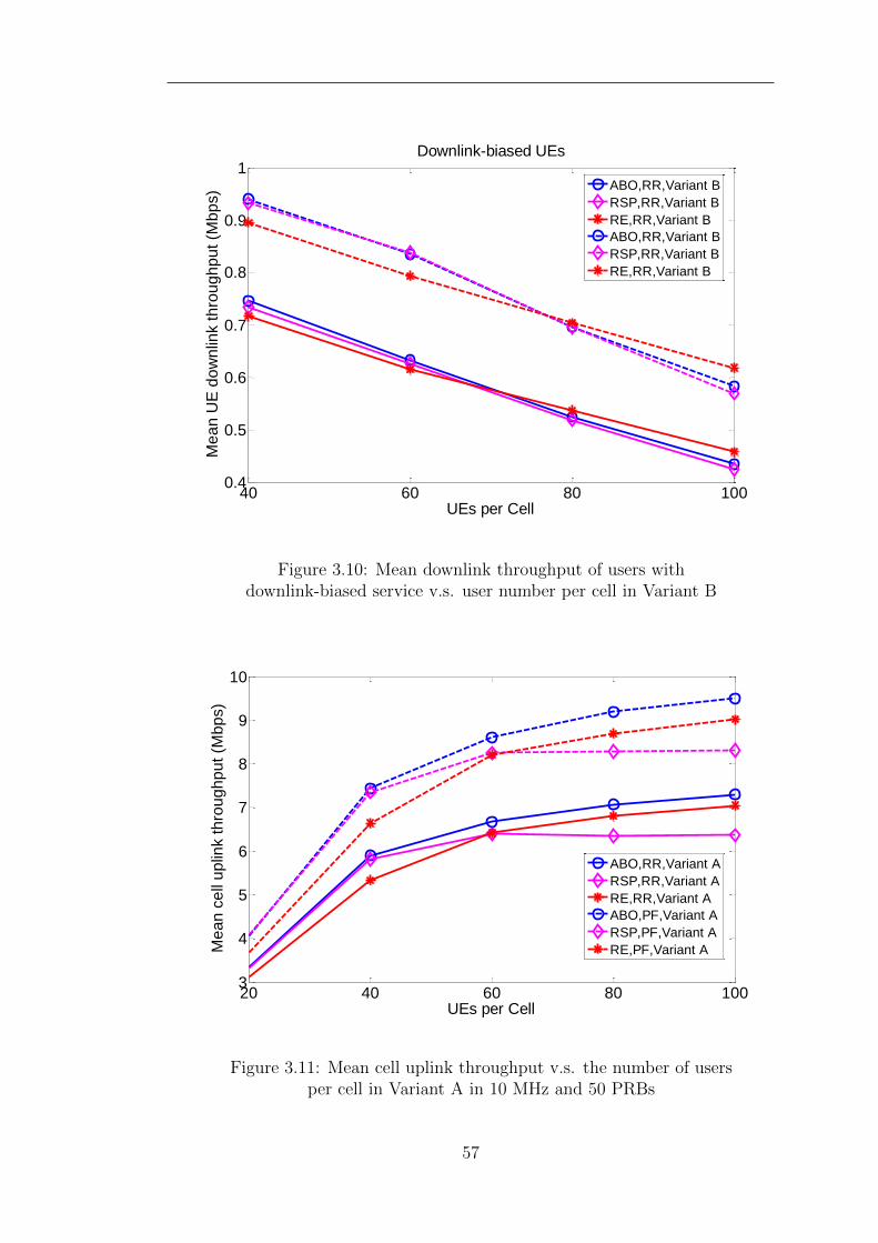
40 60 80 1000.4
0.5
0.6
0.7
0.8
0.9
1
UEs per Cell
Me
an
UE
do
wn
link t
hro
ug
hp
ut
(Mb
ps)
Downlink-biased UEs
ABO,RR,Variant B
RSP,RR,Variant B
RE,RR,Variant B
ABO,RR,Variant B
RSP,RR,Variant B
RE,RR,Variant B
Figure 3.10: Mean downlink throughput of users withdownlink-biased service v.s. user number per cell in Variant B
20 40 60 80 1003
4
5
6
7
8
9
10
UEs per Cell
Me
an
ce
ll u
plin
k t
hro
ug
hp
ut
(Mb
ps)
ABO,RR,Variant A
RSP,RR,Variant A
RE,RR,Variant A
ABO,PF,Variant A
RSP,PF,Variant A
RE,PF,Variant A
Figure 3.11: Mean cell uplink throughput v.s. the number of usersper cell in Variant A in 10 MHz and 50 PRBs
57
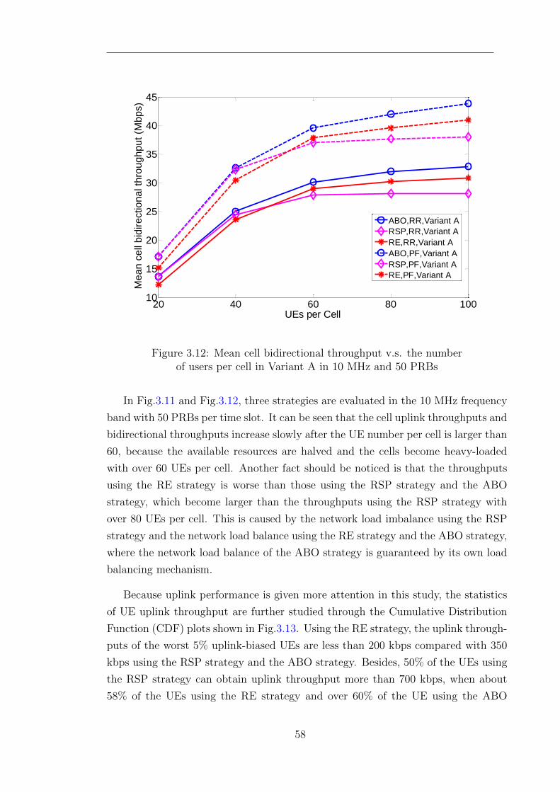
20 40 60 80 10010
15
20
25
30
35
40
45
UEs per Cell
Me
an
ce
ll b
idir
ectio
na
l th
rou
gh
pu
t (M
bp
s)
ABO,RR,Variant A
RSP,RR,Variant A
RE,RR,Variant A
ABO,PF,Variant A
RSP,PF,Variant A
RE,PF,Variant A
Figure 3.12: Mean cell bidirectional throughput v.s. the numberof users per cell in Variant A in 10 MHz and 50 PRBs
In Fig.3.11 and Fig.3.12, three strategies are evaluated in the 10 MHz frequency
band with 50 PRBs per time slot. It can be seen that the cell uplink throughputs and
bidirectional throughputs increase slowly after the UE number per cell is larger than
60, because the available resources are halved and the cells become heavy-loaded
with over 60 UEs per cell. Another fact should be noticed is that the throughputs
using the RE strategy is worse than those using the RSP strategy and the ABO
strategy, which become larger than the throughputs using the RSP strategy with
over 80 UEs per cell. This is caused by the network load imbalance using the RSP
strategy and the network load balance using the RE strategy and the ABO strategy,
where the network load balance of the ABO strategy is guaranteed by its own load
balancing mechanism.
Because uplink performance is given more attention in this study, the statistics
of UE uplink throughput are further studied through the Cumulative Distribution
Function (CDF) plots shown in Fig.3.13. Using the RE strategy, the uplink through-
puts of the worst 5% uplink-biased UEs are less than 200 kbps compared with 350
kbps using the RSP strategy and the ABO strategy. Besides, 50% of the UEs using
the RSP strategy can obtain uplink throughput more than 700 kbps, when about
58% of the UEs using the RE strategy and over 60% of the UE using the ABO
58
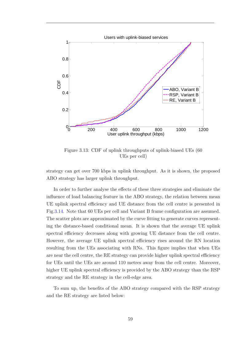
0 200 400 600 800 1000 12000
0.2
0.4
0.6
0.8
1
User uplink throughput (kbps)
CD
F
Users with uplink-biased services
ABO, Variant B
RSP, Variant B
RE, Variant B
Figure 3.13: CDF of uplink throughputs of uplink-biased UEs (60UEs per cell)
strategy can get over 700 kbps in uplink throughput. As it is shown, the proposed
ABO strategy has larger uplink throughput.
In order to further analyse the effects of these three strategies and eliminate the
influence of load balancing feature in the ABO strategy, the relation between mean
UE uplink spectral efficiency and UE distance from the cell centre is presented in
Fig.3.14. Note that 60 UEs per cell and Variant B frame configuration are assumed.
The scatter plots are approximated by the curve fitting to generate curves represent-
ing the distance-based conditional mean. It is shown that the average UE uplink
spectral efficiency decreases along with growing UE distance from the cell centre.
However, the average UE uplink spectral efficiency rises around the RN location
resulting from the UEs associating with RNs. This figure implies that when UEs
are near the cell centre, the RE strategy can provide higher uplink spectral efficiency
for UEs until the UEs are around 110 metres away from the cell centre. Moreover,
higher UE uplink spectral efficiency is provided by the ABO strategy than the RSP
strategy and the RE strategy in the cell-edge area.
To sum up, the benefits of the ABO strategy compared with the RSP strategy
and the RE strategy are listed below:
59
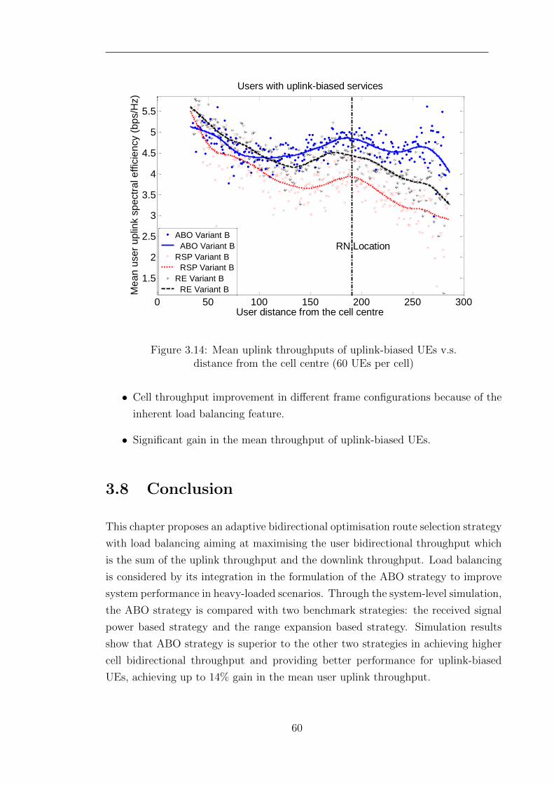
0 50 100 150 200 250 300
1.5
2
2.5
3
3.5
4
4.5
5
5.5
User distance from the cell centre
Me
an
use
r u
plin
k s
pe
ctr
al e
ffic
ien
cy (
bp
s/H
z)
Users with uplink-biased services
ABO Variant B
ABO Variant B
RSP Variant B
RSP Variant B
RE Variant B
RE Variant B
RN Location
Figure 3.14: Mean uplink throughputs of uplink-biased UEs v.s.distance from the cell centre (60 UEs per cell)
• Cell throughput improvement in different frame configurations because of the
inherent load balancing feature.
• Significant gain in the mean throughput of uplink-biased UEs.
3.8 Conclusion
This chapter proposes an adaptive bidirectional optimisation route selection strategy
with load balancing aiming at maximising the user bidirectional throughput which
is the sum of the uplink throughput and the downlink throughput. Load balancing
is considered by its integration in the formulation of the ABO strategy to improve
system performance in heavy-loaded scenarios. Through the system-level simulation,
the ABO strategy is compared with two benchmark strategies: the received signal
power based strategy and the range expansion based strategy. Simulation results
show that ABO strategy is superior to the other two strategies in achieving higher
cell bidirectional throughput and providing better performance for uplink-biased
UEs, achieving up to 14% gain in the mean user uplink throughput.
60
Chapter 4
Distributed Two-hop Proportional
Fair Resource Allocation
4.1 Introduction
This chapter focuses on distributed two-hop Proportional Fair (PF) resource alloca-
tion in LTE-Advanced networks with RNs. Resource allocation in LTE-Advanced
networks can be divided into two phases: resource partitioning and resource schedul-
ing. As an effective compromise between throughput and fairness, proportional
fair resource allocation has been widely studied in conventional single-hop cellular
networks[31, 63], OFDMA networks[58] and LTE networks[11]. In recent years, re-
search into PF resource allocation in relay enhanced OFDMA networks is emerging.
In relay enhanced LTE-Advanced networks, proportional fair (PF) resource alloca-
tion is aimed at guaranteeing two-hop match and optimising global proportional
fairness. The two-hop match is defined as equal data rates in the access links and
the corresponding backhaul links. The global proportional fairness is between all
the UEs served by the evolved Nodes B (eNB) and the RNs. Existing centralised PF
resource allocation algorithms achieve these targets at the cost of enormous channel
state information (CSI) exchange. For less CSI exchange, distributed approaches
to PF resource allocation are also considered. Existing researches about distributed
resource allocation focus on designing adaptive resource partitioning while employ-
ing a traditional single-hop PF scheduling algorithm in access links. The traditional
PF scheduling algorithm maximises single-hop proportional fairness between the
data rates in the access links rather than two-hop proportional fairness between the
end-to-end data rates in the two hops. In order to reduce CSI exchange and at
61
the same time to maximise the two-hop proportional fairness, a Distributed Two-
Hop PF (DTHPF) resource allocation scheme is proposed. The proposed scheme
includes newly designed two-hop resource scheduling algorithms and adjusted re-
source partitioning algorithms in different two-hop transmission protocols. Since
adaptive resource partitioning in different two-hop transmission protocols results
in different relations between the resource numbers of access links and backhual
links, different two-hop resource scheduling algorithms are proposed. Simulation
results demonstrate that the proposed algorithms are better than the existing dis-
tributed algorithms in obtaining better proportional fairness and larger cell-edge UE
throughputs.
4.2 Related Work
The resource allocation or scheduling techniques in LTE-Advanced networks with
RNs can be categorised into two groups, centralised approaches and distributed
approaches.
4.2.1 Centralised Approaches
Applying a centralised architecture, the resource scheduling together with the re-
source partitioning are executed by the donor eNBs. During the resource scheduling
of access links, their channel state information (CSI) ought to be collected and fed
back by the RNs.
[64] have presented an enhanced proportional fair scheduling algorithm, which
combines the resource scheduling of access links and backhaul links. The basic
frequency-time resource chuck comprises two equal time slots for the relay users.
One time slot is assigned to the access links and the other is occupied by the backhaul
links. The end-to-end data rate is calculated as the minimum rate of the two hops.
However, some resources are wasted due to the rate differences of the two hops.
In [65], Round-Robin, greedy polling and proportional fair scheduling algorithms
are extended to the OFDMA relay networks in the centralised architecture. In each
time slot, there are two equal sub-slots to accommodate direct links and backhaul
links in the first one and direct links and access links in the second one. In the second
sub-slot, a proposed partial proportional fair scheduling algorithm is applied firstly.
Based on the scheduling results, the sub-channels are allocated to the relay nodes
62
until the overall throughput of the access links in the second sub-slot is fulfilled.
[66] proposed a centralised resource allocation scheme with fixed subframe di-
vision. This resource allocation scheme includes three parts: 1) the resources are
allocated to the relay users to reduce the data stored in the relay nodes; 2) the
remaining resources go to the direct users by void filling; 3) the resources are sched-
uled between direct users and the relay nodes according to the proposed scheduling
algorithms. Four scheduling algorithms are extended from the scheduling algorithms
used in conventional networks. In two-hop scenarios, the end-to-end data rates are
calculated as the minimum rates of the two hops.
The authors in [67] proposed a RRM scheme which combines in-cell routing and
resource allocation. Both the queue length and the data rate per subchannel are
considered as performance metrics. Fixed two halved subframe division is used.
The optimisation of resource allocation in the access subframes is achieved by the
Hungarian algorithm, and the resource allocation in the backhaul subframes is based
on the queue length stored in the relay nodes. The results show that an efficient
comprise between throughput and fairness can be obtained, and the loads of relay
nodes can be balanced.
The authors in [68] used different proportional fair scheduling algorithms in two
time sub-slots. In the first sub-slot, the resources are scheduled only among the relay
users based on the conventional proportional fair scheduling algorithm. In the second
sub-slot, a weighted proportional fair scheduling algorithms is used, which considers
the two-hop mismatch in the weights. Compared with the partial proportional fair
scheduling algorithm in [65], better fairness is achieved at the expense of small
throughput loss. In [69], the authors proposed a power allocation scheme for the
backhaul links to achieve two-hop match and save energy.
The authors in [70] adopt the traditional proportional fair scheduling algorithm
in both eNBs and relay nodes with fixed resource partitioning. The resources of
access links constantly occupy 1/3 of the whole frequency band without frequency
reuse. The resources assigned to the backhaul links are assumed to match the
aggregate throughput of access links. A user routing strategy is proposed to decide
the best serving node of each user and balance the loads of serving nodes.
In [71], a two-stage centralised RRM scheme is proposed in OFDMA networks
using fixed AF relaying technology. Firstly, the users decide their transmission
modes. Sequentially, the joint subcarrier scheduling is executed and the power
control is conducted through a geometric programming method. Four interference
63
coordinated schemes are considered.
[72] proposed a heuristic resource allocation algorithm as a near optimal solu-
tion to the formulated proportional fairness problem. The problem is solved by
the Lagrangian dual decomposition method, and the algorithm is obtained using
Karush-Kuhn-Tucker conditions. A half-to-half subframe division from [73] is as-
sumed. The difference of the data rates of the two-hop links is dealt with by giving
different power to the two-hop links In addition, direct links are not considered,
since out-band RNs are assumed.
[74] have proposed two resource allocation schemes considering fairness and min-
imum data rate requirement. In this paper, the subchannels are divided into two
phases. The resource allocation problems with both selective phase assignment and
non-selective phase assignment are formulated as Lagrangian functions. The two-
hop data rate match is achieved through a power allocation algorithm.
The authors in [75] presented two joint routing and resource allocation algo-
rithms and two power allocation algorithms, which can generate three centralised
resource allocation schemes. The conditioned subcarrier allocation and mode selec-
tion algorithm and the conditioned water filling power allocation algorithm are used
in the initial iteration assuming the cochannel interference is assumed to be fixed.
The resource allocation and power allocation results are updated by employing a
joint subcarrier allocation and mode selection algorithm and a single condensation
based geometric programming power allocation algorithm.
[76] presented a semi-distributed resource allocation scheme with adaptive re-
source partitioning. This scheme consists of two parts: 1) In the backhaul sub-
frames, the resources are allocated to the direct users and the backhaul links based
on the priority matrix considering the data rates of the access links at the same
subchannel. 2) The resources are allocated to the relay users using the scheduler in
the relay nodes.
[77] focused on the resource allocation in relay networks using game theory. The
basic principle in this paper is to consider the two hops of relay users together as
a bundle. The resources can be scheduled among any two bundles using a Nash
bargaining solution. Based on the two-bundle bargaining algorithm, a multi-bundle
bargaining algorithm is proposed by applying a Hungarian algorithm to sort the
bundles into two-bundle bargaining coalitions. After the resources have been as-
signed to the bundles of the relay users, the resources are further allocated to the
access links and backhaul links in order to maximize the throughput and alleviate
64
two-hop mismatch.
The authors in [78] provided resource allocation algorithms with adaptive re-
source partitioning. To guarantee the performance, a scheduling algorithm with-
out access link reuse and a scheduling algorithm with access link reuse are pro-
posed together with the calculation of an approximation guarantee. In addition,
a greedy scheduling algorithm is derived by considering the two-hop performance.
However, only time-domain resources are considered in this work, and thus, the
multi-subcarrier diversity is neglected.
Reference [79] proposed a centralised resource allocation scheme to ensure the
proportional fairness between all the UEs associated with eNBs and RNs. In order
to simplify the mathematical analysis, the authors assume a virtual PRB for the
UEs connected to the RNs. The virtual PRBs are consumed by the backhaul links
and the access links. Their proportions are determined by the data rates in the
backhaul links and the access links. Using the gradient method and the Karush-
Kuhn-Tucker (KKT) conditions, a near-optimal solution is obtained. The impact
of backhaul links on the network performance can also be better understood.This
centralised resource allocation scheme is conducted in the time-frequency domain,
while the time domain is considered in [78].
In [80], a problem to jointly optimise subframe, PRB and power allocation is
formulated and solved by a centralised optimal joint allocation algorithm. Using a
general Lyapunov optimization framework, the three-dimensional problem is trans-
formed into the minimisation of a Lyapunov drift-plus-penalty function [81]. Then,
the main problem is decomposed into three sub-problems. Applying the continuity
relaxation and Lagrange dual decomposition in the sub-problems, the joint sub-
frame, PRB and power optimisation problem is solved with acceptable performance
and delay.
Fixed resource partitioning between access links and backhaul links will lead to
the two-hop mismatch [64, 65, 66, 67], or the proportional fair resource scheduling
between backhaul links and direct links is not considered [68, 69, 70]. Power con-
trol/allocation algorithms are used in [71, 72, 74, 75] to achieve the two-hop match.
However, they will increase complexity and highly depend on the accuracy and im-
mediateness of channel measurements. Adaptive resource partitioning is used in
[76, 77, 78, 79, 80]. In [76], the resource scheduling of two-hop links is considered to-
gether unless they are in the same subchannel, which cannot utilise channel diversity.
In [77], the subframe division between the access links and the backhaul links is not
65
considered, and the complexity of the multi-bundle bargaining algorithm is too high.
Only time-domain resource allocation is considered in [78] without utilising multi-
subcarrier diversity. The centralised resource allocation algorithms without power
allocation [79] and with power allocation [80] are best solutions so far. However,
enormous CSI exchange between the eNBs and the RNs will bring heavy burden
to the uplink signalling channels, despite multi-subchannel diversity and multi-user
diversity can be exploited using the centralised architecture.
4.2.2 Distributed Approaches
In order to reduce CSI exchange, some PF resource allocation schemes adopt a dis-
tributed architecture, in which the resource partitioning and the resource scheduling
are processed by different types of serving nodes. Particularly, the resource schedul-
ing of the access links is executed at each RN, which is supported by Type I relay in
LTE-Advanced networks; and the resource partitioning is determined by the donor
eNBs. In the existing distributed PF resource allocation schemes, great attentions
is paid to designing resource partitioning algorithms.
Several distributed resource allocation algorithms are proposed in [82] with adap-
tive and fixed resource partitioning. The algorithms follow three basic steps: 1) each
subchannel in the relay transmission phase is allocated to the user according to the
traditional Proportional fair scheduling algorithm; 2) relay nodes send their re-
quests to the eNB based on the throughput of access links; 3) the eNB allocates the
resources to the direct users first, and then sorts the resources based on the propor-
tional fairness. The resources with the smallest proportional fairness are allocated
to the backhaul links. Fixed time division, fixed frequency division and adaptive
time division are considered and evaluated in [82].
The resource allocation algorithm in [83] is comprised of two phases, a sub-carrier
allocation phase and an adaptive frame structure setting phase. In the sub-carrier
phase, relay nodes allocate the resources for their active users using proportional
fair scheduling, and the eNB executes the proportional fair scheduling for the relay
nodes and the direct users, in which the relay nodes are considered as special users
with requirement information of the relay users. In the second phase, the frame
structure is initiated with a calculated pattern based on the average throughput of
relay users and adjusted according to the real throughput. The two-hop mismatch
problem is of concern, however, the time slots are equally assigned to different relay
nodes. No frequency reuse is considered.
66
[84] presented a backhaul resource allocation scheme based on relay buffer level.
The objective of this scheme is to make the backhaul resources assigned to relay
nodes meet the traffic demand of the access links. In addition, the backhaul resource
partitioning is minimised through a suboptimal algorithm. The distributed RRM
architecture is assumed and full reuse of access subframes is applied for the access
links and direct links. Based on the half-to-half subframe division and the received
signal power based routing, this scheme is compared with a fixed backhaul resource
partitioning scheme, which uses half of the backhaul subframes, and a user based
scheme, which allocates resources to the relay nodes according to the number of
their relay users.
[85] presented two different fair resource partitioning algorithms between back-
haul links and access links, Fair-Resource-Unit (Fair-RU) and Fair-Throughput
(Fair-TP). In the Fair-RU scheme, the number of resource units for the backhaul link
is given according to the relay UEs. In the Fair-TP scheme, the resource number
for the backhaul link is assigned to make sure the identical aggregate throughput of
access links and direct links. Distributed proportional fair scheduling algorithms are
executed at the eNB and RNs separately with full frequency reuse. [86] proposed a
scheduling metric based on the delay requirement, the guaranteed bit rate and the
service priority index in order to balance the rate and the delay requirement for the
service of different QoS level. Reference [87] proposed a new resource partitioning
strategy for out-band relaying, called extended proportional fair strategy, which is
an extension of the research in [85] and [86]. In this strategy, the relay node is con-
sidered as a special user with the proportional fairness metric scaled by the number
of the connected relay users.
In [88], a distributed simplified resource allocation algorithm for in-band down-
link relay networks is provided to increase the throughput of the UEs with the
worst channel conditions. The frame is divided into access subframes and backhaul
subframes. In the access subframes, access links and direct links fully reuse the re-
sources. However, the resource number for the direct links and the backhaul links in
the backhaul subframes and the resource number of access subframes are calculated
based on the objective of maximising the throughput of the worst UEs.
[89] presents a dynamic orthogonal resource partitioning scheme with tunable
trade-off between fairness and throughput. No frequency reuse between direct links
and access links is assumed. A satisfaction metric is defined in this paper, which
is the ratio of the current data rate to the guaranteed bit rate. After the dynamic
resource partitioning with different targets is formulated, a parameter O is derived to
67
show the trade-off between fairness and throughput. Together with the parameters
O and the feedback satisfaction levels, different weights are put into the resource
partitioning algorithms to achieve better fairness or larger throughput.
The authors in [90] depicted two resource sharing schemes between different
backhaul links and two throughput distribution schemes between different access
links of one relay node. In the access subframes, full frequency reuse between access
links and direct links is assumed. In the backhaul subframes, the resources are
only shared between different backhaul links. The resource number of backhaul
link is proportional either to the latest throughput of the access links or to the
number of relay users. Two throughput distribution schemes between access links
based on different metrics are proposed in order to achieve proportional fairness and
Max-Min fairness respectively. [91] extends the resource sharing schemes and the
throughput distribution schemes to downlink transmission. In addition to [90], a
Round-Robin sharing scheme is presented in [91], which gives each active relay node
the same number of resources. In [92] and [93], the authors used a co-scheduling
strategy in the backhaul subframes, which allows direct users to utilise the remaining
resources after the resource demands of backhaul links have been satisfied. In [93],
the backhaul subframes are over-provisioned adaptively to ensure the co-scheduling
between direct users and relay nodes and to optimise performance. [94] summarised
the hard subframe division in [90] and [91] and the flexible subframe division in [92]
and [93]. More performance evaluation results are presented in [94]. However the
two-hop match and the proportional fairness are not considered.
In [95] [96], the authors use two access/backhaul subframe division algorithms.
In these algorithms, only access links can use resources in the access subframes based
on the scheduling of the queued packets with the highest AMC level. In the RS-Max
with fixed time division algorithm, the whole frame is equally divided into backhaul
subframe and access frame. With the adaptive time division, the algorithm change
the number of time slots in an iterative manner to maximise the throughput.
Two different backhaul subframe allocation schemes for multiple relay nodes
are proposed and compared in [97]. In the backhaul subframes, the Time Division
Multiplexed backhaul (TDM-backhaul) scheme allocates different subframes to the
backhaul links of different relay nodes, and the frequency division multiplexed back-
haul (FDM-backhaul) scheme distributes different resource blocks between the relay
nodes. Using the TDM-backhaul scheme, more resources can be used for the access
links because a relay node can transmit the signal to its users when the backhaul
subframe is not assigned to it. However, due to the limitation of backhaul links, the
68
TDM-backhaul scheme will not perform better than the FDM-backhaul scheme.
The authors in [98] provided a weighted proportional fair scheduling algorithm to
solve the resource waste problem caused by load imbalance between different access
links. In this paper, the whole frame is divided into the access intervals for direct
links and access links with different lengths and the relay interval for backhaul links.
Due to the different channel condition of access links and backhaul links, the resource
numbers of access links assigned to different relay nodes are different, which causes
inefficient resource usage. Using the proposed scheduling algorithm in each access
interval, a user with larger proportional fairness and less resource waste contribution
is given higher priority.
Three weighted proportional fair scheduling algorithms for the Multicast Broad-
cast Single Frequency Network (MBSFN) subframes are proposed in [99]. Both
backhaul links and access links are considered to determine how to schedule RNs at
the eNB. The weighting factor in PF scheduling algorithm 1 is the number of UEs
served by the RN. The weighting factor in PF scheduling algorithm 2 is influenced
by the ratio of the channel quality in the access links and the backhaul links, and
the overall importance of all the UEs connected to the RNs. The weighting factor
in PF scheduling algorithm 3 is derived by the ratio of the data rates in the access
links and the backhaul links. However, these schedulers are not proposed to solve
the PF resource allocation problem. The PF scheduling for the access links is not
discussed.
The authors in [100] proposed a distributed resource allocation scheme. The
proposed resource allocation scheme is divided into two sub-tasks, RN resource
allocation and eNB resource allocation. Non-cooperative game framework is used
to design the RN resource allocation. The authors adopted a strategy to partition
less resources for the UEs served by the RNs and keep more resources for single-hop
transmission. The proposed scheme is aiming at providing high cell throughput and
guaranteeing the minimum data rate requirements of UEs. Simulation results show
that this scheme makes a great contribution in improving the cell throughput and
reducing the outage probability. However, proportional fairness is not considered.
Semi-static PF-based partition schemes are designed for the full reuse scenario
in [101, 102] and none reuse scenario in [54]. Through formulating the generalised
PF problem and solving it by the Lagrange multiplier algorithm, these two optimal
resource partitioning patterns are derived based on the number of relay users and the
average throughputs of access links and backhaul links. Proportional fair scheduling
69
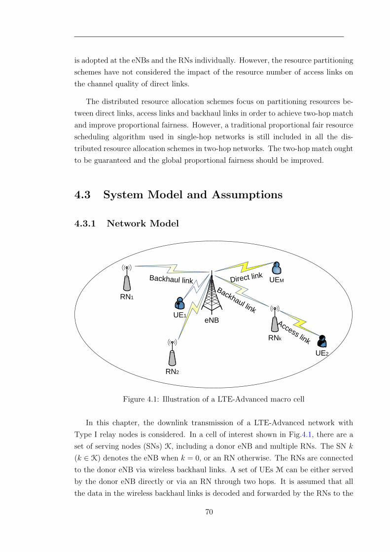
is adopted at the eNBs and the RNs individually. However, the resource partitioning
schemes have not considered the impact of the resource number of access links on
the channel quality of direct links.
The distributed resource allocation schemes focus on partitioning resources be-
tween direct links, access links and backhaul links in order to achieve two-hop match
and improve proportional fairness. However, a traditional proportional fair resource
scheduling algorithm used in single-hop networks is still included in all the dis-
tributed resource allocation schemes in two-hop networks. The two-hop match ought
to be guaranteed and the global proportional fairness should be improved.
4.3 System Model and Assumptions
4.3.1 Network Model
eNBUE1
Backhaul link Direct link
Access linkRNk
Backhaul link
RN1
UE2
RN2
UEM
Figure 4.1: Illustration of a LTE-Advanced macro cell
In this chapter, the downlink transmission of a LTE-Advanced network with
Type I relay nodes is considered. In a cell of interest shown in Fig.4.1, there are a
set of serving nodes (SNs) K, including a donor eNB and multiple RNs. The SN k
(k ∈ K) denotes the eNB when k = 0, or an RN otherwise. The RNs are connected
to the donor eNB via wireless backhaul links. A set of UEs M can be either served
by the donor eNB directly or via an RN through two hops. It is assumed that all
the data in the wireless backhaul links is decoded and forwarded by the RNs to the
70
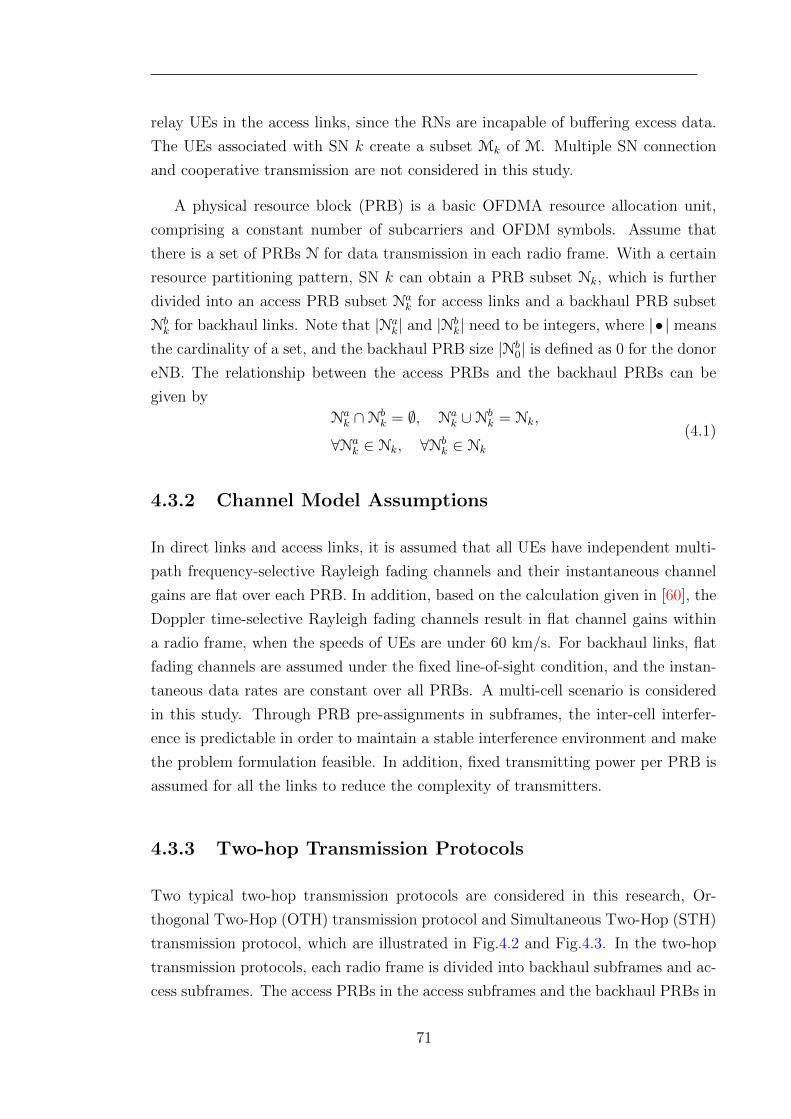
relay UEs in the access links, since the RNs are incapable of buffering excess data.
The UEs associated with SN k create a subset Mk of M. Multiple SN connection
and cooperative transmission are not considered in this study.
A physical resource block (PRB) is a basic OFDMA resource allocation unit,
comprising a constant number of subcarriers and OFDM symbols. Assume that
there is a set of PRBs N for data transmission in each radio frame. With a certain
resource partitioning pattern, SN k can obtain a PRB subset Nk, which is further
divided into an access PRB subset Nak for access links and a backhaul PRB subset
Nbk for backhaul links. Note that |Na
k| and |Nbk| need to be integers, where | • | means
the cardinality of a set, and the backhaul PRB size |Nb0| is defined as 0 for the donor
eNB. The relationship between the access PRBs and the backhaul PRBs can be
given by
Nak ∩Nb
k = ∅, Nak ∪Nb
k = Nk,
∀Nak ∈ Nk, ∀Nb
k ∈ Nk
(4.1)
4.3.2 Channel Model Assumptions
In direct links and access links, it is assumed that all UEs have independent multi-
path frequency-selective Rayleigh fading channels and their instantaneous channel
gains are flat over each PRB. In addition, based on the calculation given in [60], the
Doppler time-selective Rayleigh fading channels result in flat channel gains within
a radio frame, when the speeds of UEs are under 60 km/s. For backhaul links, flat
fading channels are assumed under the fixed line-of-sight condition, and the instan-
taneous data rates are constant over all PRBs. A multi-cell scenario is considered
in this study. Through PRB pre-assignments in subframes, the inter-cell interfer-
ence is predictable in order to maintain a stable interference environment and make
the problem formulation feasible. In addition, fixed transmitting power per PRB is
assumed for all the links to reduce the complexity of transmitters.
4.3.3 Two-hop Transmission Protocols
Two typical two-hop transmission protocols are considered in this research, Or-
thogonal Two-Hop (OTH) transmission protocol and Simultaneous Two-Hop (STH)
transmission protocol, which are illustrated in Fig.4.2 and Fig.4.3. In the two-hop
transmission protocols, each radio frame is divided into backhaul subframes and ac-
cess subframes. The access PRBs in the access subframes and the backhaul PRBs in
71
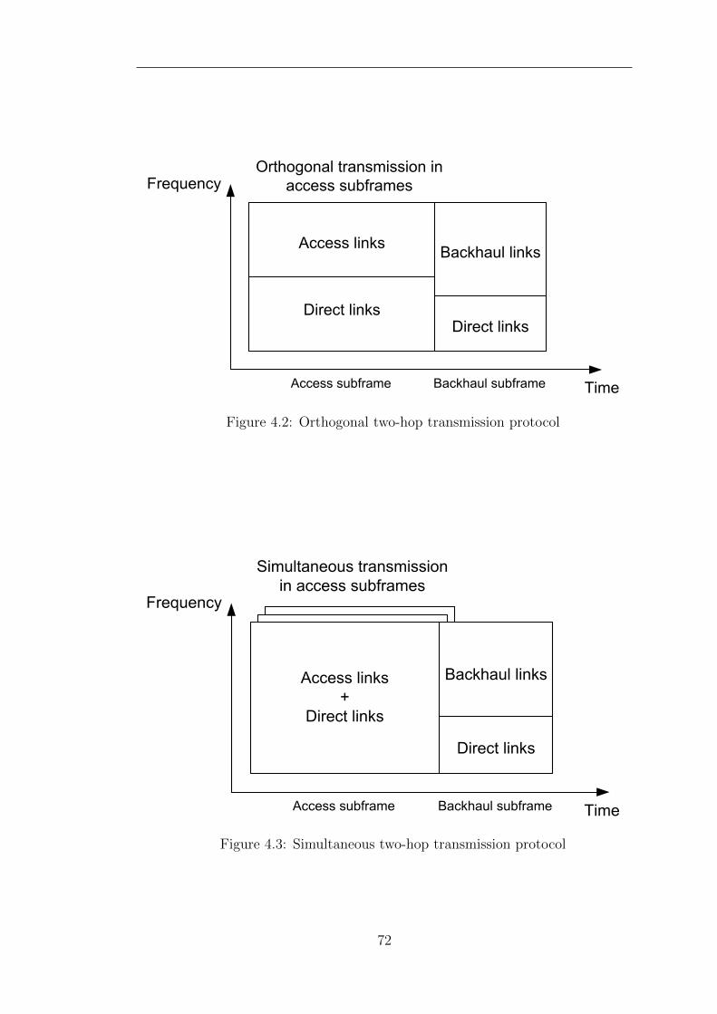
Figure 4.2: Orthogonal two-hop transmission protocol
Figure 4.3: Simultaneous two-hop transmission protocol
72
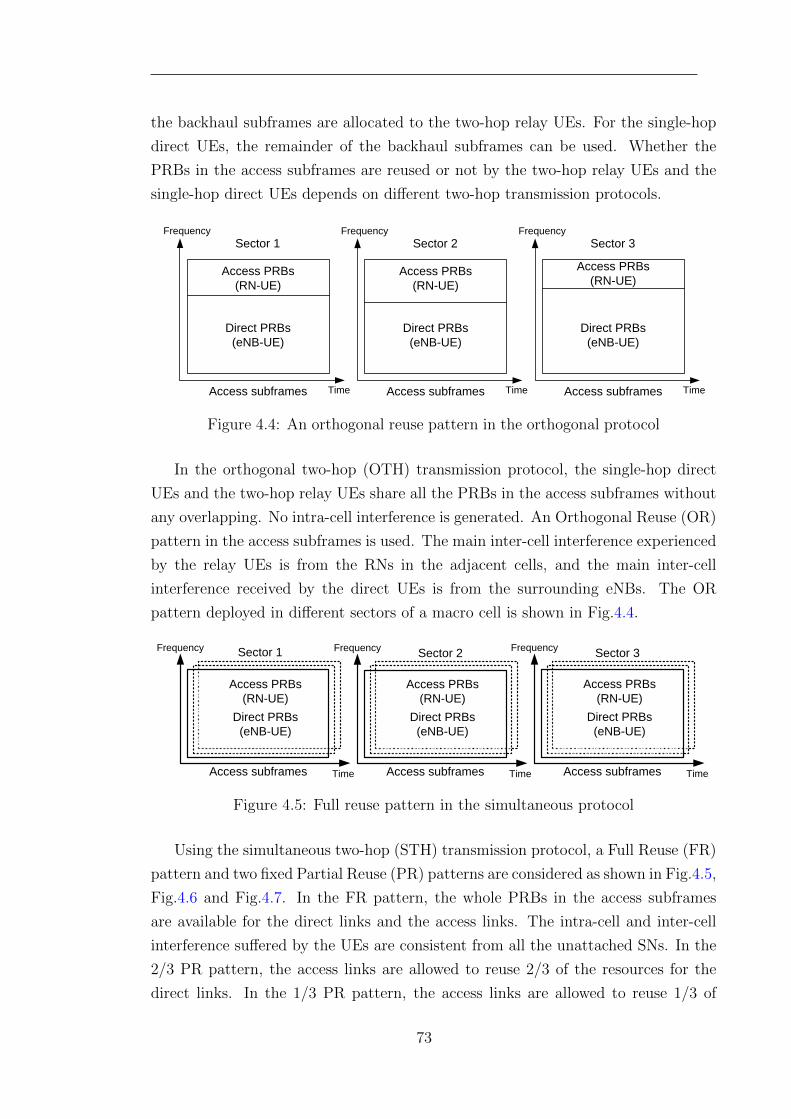
the backhaul subframes are allocated to the two-hop relay UEs. For the single-hop
direct UEs, the remainder of the backhaul subframes can be used. Whether the
PRBs in the access subframes are reused or not by the two-hop relay UEs and the
single-hop direct UEs depends on different two-hop transmission protocols.
Access subframes Time
Frequency
Direct PRBs(eNB-UE)
Access PRBs (RN-UE)
Sector 1
Access subframes Time
Frequency
Direct PRBs(eNB-UE)
Access PRBs (RN-UE)
Sector 2
Access subframes Time
Frequency
Direct PRBs(eNB-UE)
Access PRBs (RN-UE)
Sector 3
Figure 4.4: An orthogonal reuse pattern in the orthogonal protocol
In the orthogonal two-hop (OTH) transmission protocol, the single-hop direct
UEs and the two-hop relay UEs share all the PRBs in the access subframes without
any overlapping. No intra-cell interference is generated. An Orthogonal Reuse (OR)
pattern in the access subframes is used. The main inter-cell interference experienced
by the relay UEs is from the RNs in the adjacent cells, and the main inter-cell
interference received by the direct UEs is from the surrounding eNBs. The OR
pattern deployed in different sectors of a macro cell is shown in Fig.4.4.
Access PRBs (RN-UE)
Time
Frequency
Access subframes
Direct PRBs(eNB-UE)
Access PRBs (RN-UE)
Time
Frequency
Access subframes
Direct PRBs(eNB-UE)
Access PRBs (RN-UE)
Time
Frequency
Access subframes
Direct PRBs(eNB-UE)
Sector 1 Sector 2 Sector 3
Figure 4.5: Full reuse pattern in the simultaneous protocol
Using the simultaneous two-hop (STH) transmission protocol, a Full Reuse (FR)
pattern and two fixed Partial Reuse (PR) patterns are considered as shown in Fig.4.5,
Fig.4.6 and Fig.4.7. In the FR pattern, the whole PRBs in the access subframes
are available for the direct links and the access links. The intra-cell and inter-cell
interference suffered by the UEs are consistent from all the unattached SNs. In the
2/3 PR pattern, the access links are allowed to reuse 2/3 of the resources for the
direct links. In the 1/3 PR pattern, the access links are allowed to reuse 1/3 of
73
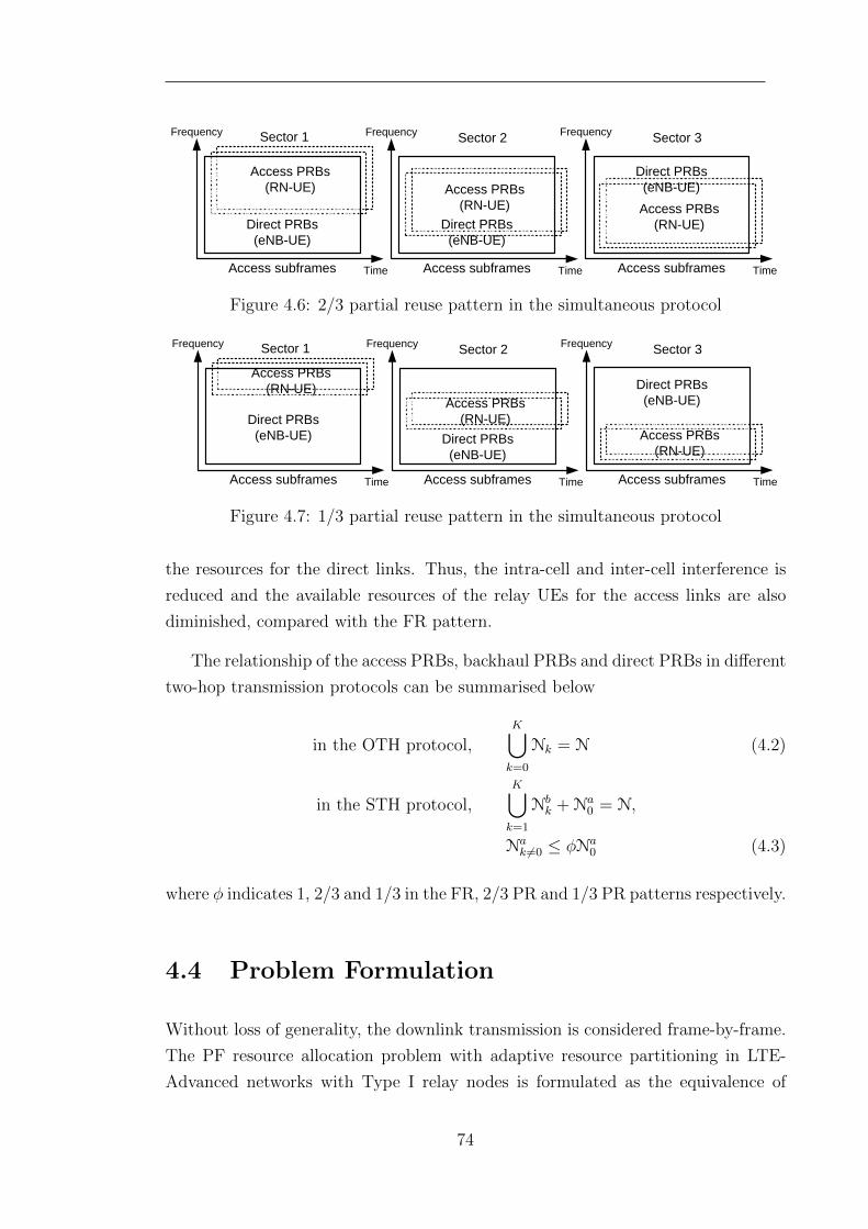
Access PRBs (RN-UE)
Time
Frequency
Access subframes
Direct PRBs(eNB-UE)
Access PRBs (RN-UE)
Time
Frequency
Access subframes
Direct PRBs(eNB-UE)
Access PRBs (RN-UE)
Time
Frequency
Access subframes
Direct PRBs(eNB-UE)
Sector 1 Sector 2 Sector 3
Figure 4.6: 2/3 partial reuse pattern in the simultaneous protocol
Access PRBs (RN-UE)
Time
Frequency
Access subframes
Direct PRBs(eNB-UE)
Access PRBs (RN-UE)
Time
Frequency
Access subframes
Direct PRBs(eNB-UE)
Access PRBs (RN-UE)
Time
Frequency
Access subframes
Direct PRBs(eNB-UE)
Sector 1 Sector 2 Sector 3
Figure 4.7: 1/3 partial reuse pattern in the simultaneous protocol
the resources for the direct links. Thus, the intra-cell and inter-cell interference is
reduced and the available resources of the relay UEs for the access links are also
diminished, compared with the FR pattern.
The relationship of the access PRBs, backhaul PRBs and direct PRBs in different
two-hop transmission protocols can be summarised below
in the OTH protocol,K⋃k=0
Nk = N (4.2)
in the STH protocol,K⋃k=1
Nbk + Na
0 = N,
Nak 6=0 ≤ φNa
0 (4.3)
where φ indicates 1, 2/3 and 1/3 in the FR, 2/3 PR and 1/3 PR patterns respectively.
4.4 Problem Formulation
Without loss of generality, the downlink transmission is considered frame-by-frame.
The PF resource allocation problem with adaptive resource partitioning in LTE-
Advanced networks with Type I relay nodes is formulated as the equivalence of
74
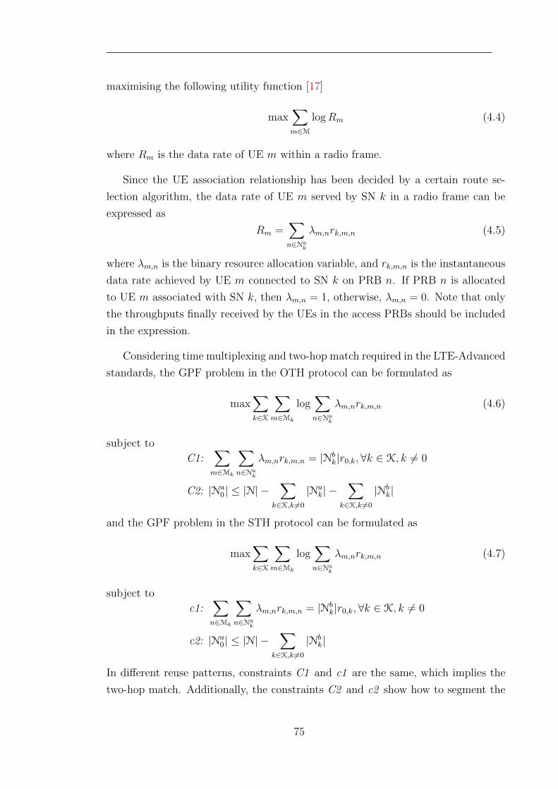
maximising the following utility function [17]
max∑m∈M
logRm (4.4)
where Rm is the data rate of UE m within a radio frame.
Since the UE association relationship has been decided by a certain route se-
lection algorithm, the data rate of UE m served by SN k in a radio frame can be
expressed as
Rm =∑n∈Na
k
λm,nrk,m,n (4.5)
where λm,n is the binary resource allocation variable, and rk,m,n is the instantaneous
data rate achieved by UE m connected to SN k on PRB n. If PRB n is allocated
to UE m associated with SN k, then λm,n = 1, otherwise, λm,n = 0. Note that only
the throughputs finally received by the UEs in the access PRBs should be included
in the expression.
Considering time multiplexing and two-hop match required in the LTE-Advanced
standards, the GPF problem in the OTH protocol can be formulated as
max∑k∈K
∑m∈Mk
log∑n∈Na
k
λm,nrk,m,n (4.6)
subject to
C1:∑m∈Mk
∑n∈Na
k
λm,nrk,m,n = |Nbk|r0,k,∀k ∈ K, k 6= 0
C2: |Na0| ≤ |N| −
∑k∈K,k 6=0
|Nak| −
∑k∈K,k 6=0
|Nbk|
and the GPF problem in the STH protocol can be formulated as
max∑k∈K
∑m∈Mk
log∑n∈Na
k
λm,nrk,m,n (4.7)
subject to
c1:∑n∈Mk
∑n∈Na
k
λm,nrk,m,n = |Nbk|r0,k,∀k ∈ K, k 6= 0
c2: |Na0| ≤ |N| −
∑k∈K,k 6=0
|Nbk|
In different reuse patterns, constraints C1 and c1 are the same, which implies the
two-hop match. Additionally, the constraints C2 and c2 show how to segment the
75
entire PRBs in a radio frame.
The Generalised Proportional Fairness (GPF) problems in (4.6) and (4.7) are
not convex optimisation problems, since UEs’ data rates R is not a convex set with
binary variables λ ∈ {0, 1}. In order to make the GPF problem tractable, the binary
variables λ are allowed to take any value between 0 and 1, λ ∈ [0, 1], so that R is
a convex set and the GPF problems in (4.6) and (4.7) become convex optimisation
problem[103]. The method of Lagrange multipliers can then be used to solve the
GPF problems.
4.5 Problem Relaxation
In this section, our aim is to solve the formulated GPF problem in different two-
hop transmission protocols. Using a distributed architecture, the GPF problem
can be decomposed into two sub-problems, i.e., a resource portioning problem with
given scheduling results, and a resource scheduling problem considering the known
two-hop resource segments.
4.5.1 Adaptive PF Resource Partitioning
According to the findings in [31, 58] and the system model defined in this chapter,
the throughput of UE m in a PF scheduler can be approximated by its average data
rate per PRB, the average allocated PRB number and a PF scheduling gain Gm,k.
The PF scheduling gain is based on the throughput comparison between the PF
scheduling the Round-robin scheduling, which are scheduling the same UEs on the
same PRBs.
Rm ≈ Gm,k|Nk||Mk|
rm,k (4.8)
where Gm,k depends on the channel states of all the UEs in the scheduler and are
independent of the PRB numbers to be scheduled.
In [54, 102], the resource partitioning problems in the OTH and STH transmis-
sion protocols are simplified into a PRB number-related logarithmic sum maximi-
sation function through substituting (4.8) into (4.6) and (4.7)
max∑k∈K
|Mk| log |Nak| (4.9)
76
Besides, the relationship between the backhaul PRB numbers and the access PRB
numbers can be derived by substituting (4.8) into constraint C1 or c1. A backhaul-
to-access ratio θk is defined for every RN k as
θk =|Nb
k||Na
k|=
∑m∈Mk
Gm,krm,k
|Mk|r0,k(4.10)
where θk indicates the ratio of the data rates per PRB of the backhaul link to the
aggregate access links of RN k. Note that the backhaul-to-access ratios can be
estimated by the previous average data rates.
Two adaptive resource partitioning algorithms in the OTH and STH protocols
have been proposed in [54, 102]. However, these algorithms are based on OFDMA
networks without considering the integrated subframe division, which is not practical
for relay enhanced LTE-Advanced networks. In what follows, these adaptive resource
partitioning algorithms are adjusted for the LTE-Advanced networks, considering
the integrated subframe division indicator α with only a slight increase in complexity.
In the OTH protocol The adaptive PF resource partitioning algorithm in the
OTH protocol is described in the following steps.
Step 1: By only considering constraint C2 and solving (4.9) by the Lagrange
multiplier algorithm, perfect resource partitioning results in the OTH protocol can
be readily derived [54].
|Na0| =|M0||N||M|
|Nak| =
|Mk||N|(1 + θk)|M|
=|Nb
k|θk
, ∀k ∈ K, k 6= 0
(4.11)
Step 2: The backhaul subframe number α is determined by the minimum integer
which fulfils all the requirements of backhaul PRB.
α = min(T − 1, d∑
k∈K,k 6=0
|Mk|T|M|
θk1 + θk
e) (4.12)
where T is the subframe number in a radio frame and d•e means rounding up to the
nearest integer.
77
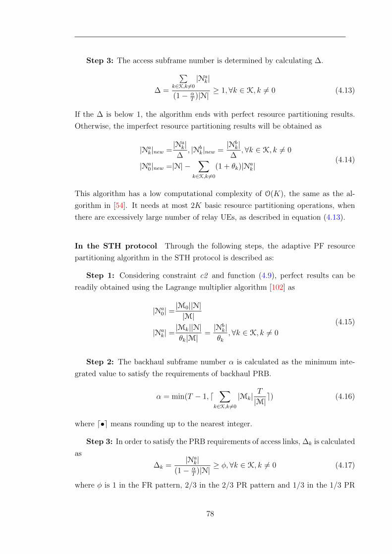
Step 3: The access subframe number is determined by calculating ∆.
∆ =
∑k∈K,k 6=0
|Nak|
(1− αT
)|N|≥ 1,∀k ∈ K, k 6= 0 (4.13)
If the ∆ is below 1, the algorithm ends with perfect resource partitioning results.
Otherwise, the imperfect resource partitioning results will be obtained as
|Nak|new =
|Nak|
∆, |Nb
k|new =|Nb
k|∆
,∀k ∈ K, k 6= 0
|Na0|new =|N| −
∑k∈K,k 6=0
(1 + θk)|Nak|
(4.14)
This algorithm has a low computational complexity of O(K), the same as the al-
gorithm in [54]. It needs at most 2K basic resource partitioning operations, when
there are excessively large number of relay UEs, as described in equation (4.13).
In the STH protocol Through the following steps, the adaptive PF resource
partitioning algorithm in the STH protocol is described as:
Step 1: Considering constraint c2 and function (4.9), perfect results can be
readily obtained using the Lagrange multiplier algorithm [102] as
|Na0| =|M0||N||M|
|Nak| =|Mk||N|θk|M|
=|Nb
k|θk
,∀k ∈ K, k 6= 0
(4.15)
Step 2: The backhaul subframe number α is calculated as the minimum inte-
grated value to satisfy the requirements of backhaul PRB.
α = min(T − 1, d∑
k∈K,k 6=0
|Mk|T
|M|e) (4.16)
where d•e means rounding up to the nearest integer.
Step 3: In order to satisfy the PRB requirements of access links, ∆k is calculated
as
∆k =|Na
k|(1− α
T)|N|
≥ φ,∀k ∈ K, k 6= 0 (4.17)
where φ is 1 in the FR pattern, 2/3 in the 2/3 PR pattern and 1/3 in the 1/3 PR
78
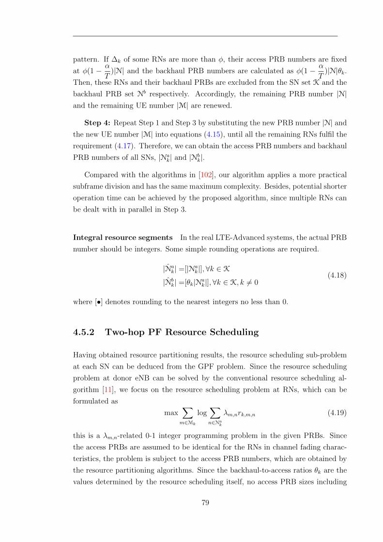
pattern. If ∆k of some RNs are more than φ, their access PRB numbers are fixed
at φ(1 − α
T)|N| and the backhaul PRB numbers are calculated as φ(1 − α
T)|N|θk.
Then, these RNs and their backhaul PRBs are excluded from the SN set K and the
backhaul PRB set Nb respectively. Accordingly, the remaining PRB number |N|and the remaining UE number |M| are renewed.
Step 4: Repeat Step 1 and Step 3 by substituting the new PRB number |N| and
the new UE number |M| into equations (4.15), until all the remaining RNs fulfil the
requirement (4.17). Therefore, we can obtain the access PRB numbers and backhaul
PRB numbers of all SNs, |Nak| and |Nb
k|.
Compared with the algorithms in [102], our algorithm applies a more practical
subframe division and has the same maximum complexity. Besides, potential shorter
operation time can be achieved by the proposed algorithm, since multiple RNs can
be dealt with in parallel in Step 3.
Integral resource segments In the real LTE-Advanced systems, the actual PRB
number should be integers. Some simple rounding operations are required.
|Nak| =[|Na
k|], ∀k ∈ K
|Nbk| =[θk|Na
k|],∀k ∈ K, k 6= 0(4.18)
where [•] denotes rounding to the nearest integers no less than 0.
4.5.2 Two-hop PF Resource Scheduling
Having obtained resource partitioning results, the resource scheduling sub-problem
at each SN can be deduced from the GPF problem. Since the resource scheduling
problem at donor eNB can be solved by the conventional resource scheduling al-
gorithm [11], we focus on the resource scheduling problem at RNs, which can be
formulated as
max∑m∈Mk
log∑n∈Na
k
λm,nrk,m,n (4.19)
this is a λm,n-related 0-1 integer programming problem in the given PRBs. Since
the access PRBs are assumed to be identical for the RNs in channel fading charac-
teristics, the problem is subject to the access PRB numbers, which are obtained by
the resource partitioning algorithms. Since the backhaul-to-access ratios θk are the
values determined by the resource scheduling itself, no access PRB sizes including
79
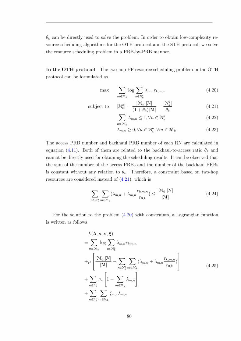
θk can be directly used to solve the problem. In order to obtain low-complexity re-
source scheduling algorithms for the OTH protocol and the STH protocol, we solve
the resource scheduling problem in a PRB-by-PRB manner.
In the OTH protocol The two-hop PF resource scheduling problem in the OTH
protocol can be formulated as
max∑m∈Mk
log∑n∈Na
k
λm,nrk,m,n (4.20)
subject to |Nak| =
|Mk||N|(1 + θk)|M|
=|Nb
k|θk
(4.21)∑m∈Mk
λm,n ≤ 1, ∀n ∈ Nak (4.22)
λm,n ≥ 0,∀n ∈ Nak,∀m ∈Mk (4.23)
The access PRB number and backhaul PRB number of each RN are calculated in
equation (4.11). Both of them are related to the backhaul-to-access ratio θk and
cannot be directly used for obtaining the scheduling results. It can be observed that
the sum of the number of the access PRBs and the number of the backhaul PRBs
is constant without any relation to θk. Therefore, a constraint based on two-hop
resources are considered instead of (4.21), which is
∑n∈Na
k
∑m∈Mk
(λm,n + λm,nrk,m,nr0,k
) ≤ |M0||N||M|
(4.24)
For the solution to the problem (4.20) with constraints, a Lagrangian function
is written as follows
L(λ, µ,ν, ξ)
=∑m∈Mk
log∑n∈Na
k
λm,nrk,m,n
+µ
|M0||N||M|
−∑n∈Na
k
∑m∈Mk
(λm,n + λm,nrk,m,nr0,k
)
+
∑n∈Na
k
νn
[1−
∑m∈Mk
λm,n
]+
∑n∈Na
k
∑m∈Mk
ξm,nλm,n
(4.25)
80
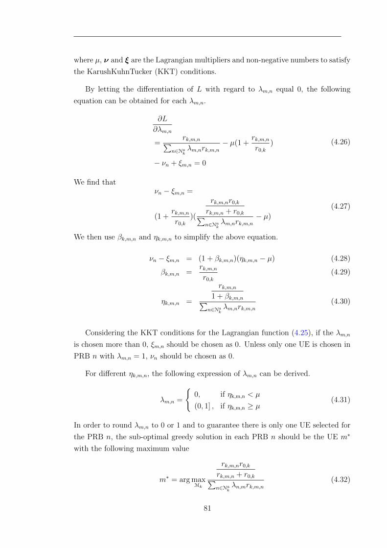
where µ, ν and ξ are the Lagrangian multipliers and non-negative numbers to satisfy
the KarushKuhnTucker (KKT) conditions.
By letting the differentiation of L with regard to λm,n equal 0, the following
equation can be obtained for each λm,n.
∂L
∂λm,n
=rk,m,n∑
n∈Nakλm,nrk,m,n
− µ(1 +rk,m,nr0,k
)
− νn + ξm,n = 0
(4.26)
We find thatνn − ξm,n =
(1 +rk,m,nr0,k
)(
rk,m,nr0,krk,m,n + r0,k∑n∈Na
kλm,nrk,m,n
− µ)
(4.27)
We then use βk,m,n and ηk,m,n to simplify the above equation.
νn − ξm,n = (1 + βk,m,n)(ηk,m,n − µ) (4.28)
βk,m,n =rk,m,nr0,k
(4.29)
ηk,m,n =
rk,m,n1 + βk,m,n∑
n∈Nakλm,nrk,m,n
(4.30)
Considering the KKT conditions for the Lagrangian function (4.25), if the λm,n
is chosen more than 0, ξm,n should be chosen as 0. Unless only one UE is chosen in
PRB n with λm,n = 1, νn should be chosen as 0.
For different ηk,m,n, the following expression of λm,n can be derived.
λm,n =
{0,
(0, 1] ,
if ηk,m,n < µ
if ηk,m,n ≥ µ(4.31)
In order to round λm,n to 0 or 1 and to guarantee there is only one UE selected for
the PRB n, the sub-optimal greedy solution in each PRB n should be the UE m∗
with the following maximum value
m∗ = arg maxMk
rk,m,nr0,krk,m,n + r0,k∑n∈Na
kλn,mrk,m,n
(4.32)
81
By replacing∑
n∈Nakλn,mrk,m,n with the historical data rate Rm,k(t− 1) of UE m
associated with RN k, a distributed two-hop resource scheduling algorithm for the
OTH protocol is proposed as
m = arg maxMk
rk,m,nr0,krk,m,n + r0,kRm,k(t− 1)
,∀n ∈ Nak (4.33)
After each time interval, Rm,k(t− 1) is updated as
Rm,k(t) =(1− 1
W)Rm,k(t− 1)+
1
W
∑n∈Na
k
λn,mrk,m,n(4.34)
where W is the average filter window length.
Using the proposed resource scheduling algorithm, the proportional fairness of
end-to-end data rates is supposed to be maximised. Thus, based on the findings in
[31, 58], the end-to-end data rate of each relay UE can be approximated as
Rm ≈ G∗m,k|Na
k|+ |Nbk|
|Mk|rm,kr0,krm,k + r0,k
(4.35)
where G∗m,k is the scheduling gain of the proposed algorithm compared with the
Round-Robin scheduling. It can be seen from the approximation in (4.35) that the
difference between the end-to-end data rates of relay UEs can be reduced compared
with the conventional single-hop PF scheduling algorithm.
In the STH protocol Based on the adaptive resource partitioning in the STH
protocol, the two-hop resource scheduling problem for the STH protocol is subject
to four independent constraints
max∑m∈Mk
log∑n∈Na
k
λm,nrk,m,n (4.36)
subject to |Nak| ≤ φ(1− α
T)|N| (4.37)
|Nbk| ≤
|Mk||N||M|
(4.38)∑m∈Mk
λm,n = 1,∀n ∈ |Nak| (4.39)
λm,n ≥ 1,∀n ∈ Nak,∀m ∈Mk (4.40)
82
In order to solve this resource scheduling problem, We consider the Lagrangian
function with the KKT conditions
L(λ, ξ, µ,ν)
=∑m∈Mk
log∑n∈Na
k
λm,nrk,m,n
+σ
φ(1− α
T)|N| −
∑n∈Na
k
∑m∈Mk
λm,n
+µ
|M0||N||M|
−∑n∈Na
k
∑m∈Mk
λm,nrk,m,nr0,k
+
∑n∈Na
k
νn
[1−
∑m∈Mk
λm,n
]+
∑n∈Na
k
∑m∈Mk
ξm,nλm,n
(4.41)
where λ, σ, µ, ν and ξ are the Lagrangian multipliers and non-negative numbers to
satisfy the KKT conditions.
By letting the differentiation of L with regard to λm,n equal 0, the following
equation can be obtained for each λm,n.
∂L
∂λm,n=
rk,m,n∑n∈Na
kλm,nrk,m,n
− σ − µrk,m,nr0,k
− νn + ξm,n = 0(4.42)
If the constraint (4.38) is not satisfied, µ can be any number not less than 0. We
have
νn − ξm,n =rk,m,nr0,k
(r0,k∑
n∈Nakλn,mrk,m,n
− µ)− σ (4.43)
Similar to the solution of the resource scheduling problem in the OTH protocol, the
chosen UE should maximise the following value.
m = arg maxMk
r0,k∑n∈Na
kλn,mrk,m,n
(4.44)
If the constraint (4.38) is satisfied, µ should be 0 to satisfy the KKT condition.
83
Therefore, the UE should be chosen according to the following metric.
m = arg maxMk
rk,m,n∑n∈Na
kλn,mrk,m,n
(4.45)
In order to solve the PF scheduling problem with two constraints, a two-hop
schedule-and-confirm algorithm with two stages is proposed.
Stage 1: The initial scheduling results accounting for constraint (4.37) can be
obtained easily through similar procedures as in the OTH protocol. As for PRB n,
it is scheduled to UE m with the highest ratio of the current data rate to the history
data rate.m = arg max
Mk
rk,m,n∑n∈Na
k
λm,nrk,m,n
= arg maxMk
rk,m,nRk,m(t− 1)
(4.46)
and the preliminary variable λm,n is set to 1. For those UEs that are not chosen,
λm∗,n is 0.
Stage 2: After all the access PRBs have been scheduled according to (4.46),
they should be confirmed by the scheduling of the backhaul PRBs. Because of
constraints (4.38) and (C1 ), the access PRB n allocated to UE m is confirmed by
m = arg maxMk
r0,k∑n∈Nb
k
λbn,mr0,k
= arg maxMk
r0,k∑n∈Na
k
λm,nrk,m,n
(4.47)
where λbn,m is the resource allocation variable in the backhaul links. If the access
PRB scheduling is confirmed, the final resource allocation variable λm,n and the
corresponding λbn,m are set to 1, otherwise, the confirmation of the next access PRB
will begin. Stage 2 repeats until the scheduling of all access PRBs are confirmed
or all the backhaul PRBs are scheduled. After each time interval, Rm,k(t − 1) is
updated as
Rm,k(t) =(1− 1
W)Rm,k(t− 1)+
1
W
∑n∈Na
k
λn,mrk,m,n(4.48)
where W is the average filter window length.
84

Since the PF resource scheduling problem in the STH protocol is constrained by
the resources of both hops, the end-to-end data rates of relay UEs are between two
values, RAccessm and RBackhaul
m , for the two hops.
RAccessm ≈ Gm,k
|Nak|
|Mk|rm,k
RBackhaulm ≈ |N
bk|
|Mk|r0,k
(4.49)
where Gm,k is the scheduling gain of the conventional PF scheduling algorithm com-
pared with the Round-Robin scheduling algorithm. Which value the end-to-end
data rates are closer to depends on which constraint is stricter.
CSI exchange analysis By using the distributed resource allocation scheme pro-
posed in this chapter, the CSI exchange between the donor eNBs and the RNs can
be reduced significantly. In the centralised resource allocation schemes, the channel
information of the relay UEs in all the PRBs should be transmitted to the donor
eNB periodically by each RN, and the resource scheduling decision of relay UEs in
the assigned PRBs are transmitted to each RN by the donor eNB. In the proposed
scheme, only the sum of data rates of the attached relay UEs in the access links
should be transmitted by each RN, and the donor eNBs inform the RNs about the
PRBs partitioned for them. Thus, the occupied resources in the control channels of
backhaul links by the CSI exchange using the centralised scheme is |Mk|× |N| times
that for the proposed distributed scheme.
4.6 Performance Evaluation
4.6.1 Simulation Scenarios
According to the LTE self-evaluation methodology [14], a semi-static system-level
Matlab simulation platform is developed to evaluate downlink performance. Using
the wrap-around technique, seven 3-sectored macro cells are generated with a fixed
numbers of UEs randomly dropped in them. In each cell, a fixed number of RNs
are located on the fringe of the cell with the same distance of half of the inter-site
distance from the eNB. The simulated network is illustrated in Fig.4.8. The details
of simulation parameters are listed in Table 4.1.
85
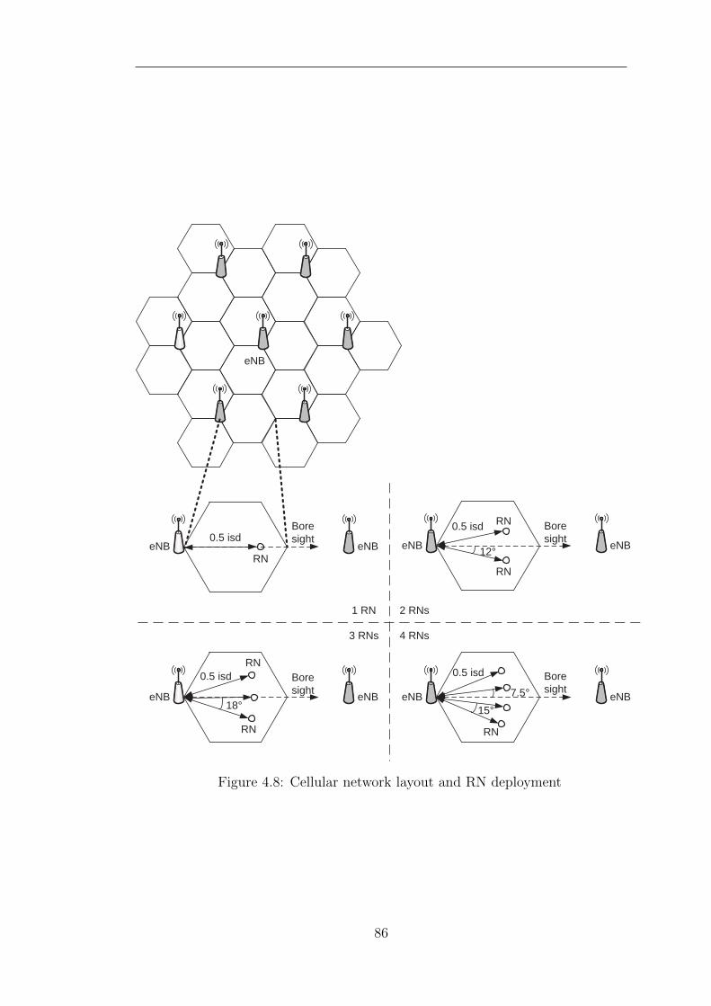
eNB
Boresight0.5 isd
RNeNB eNB
Boresight
0.5 isd RN
eNB eNB
RN
12°
Boresight
0.5 isd
eNB eNB
RN
7.5°15°
Boresight
RN
eNB eNB
RN
18°
0.5 isd
1 RN 2 RNs
3 RNs 4 RNs
Figure 4.8: Cellular network layout and RN deployment
86
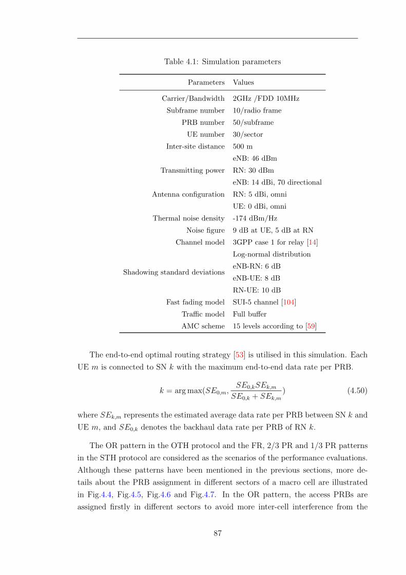
Table 4.1: Simulation parameters
Parameters Values
Carrier/Bandwidth 2GHz /FDD 10MHz
Subframe number 10/radio frame
PRB number 50/subframe
UE number 30/sector
Inter-site distance 500 m
Transmitting power
eNB: 46 dBm
RN: 30 dBm
Antenna configuration
eNB: 14 dBi, 70 directional
RN: 5 dBi, omni
UE: 0 dBi, omni
Thermal noise density -174 dBm/Hz
Noise figure 9 dB at UE, 5 dB at RN
Channel model 3GPP case 1 for relay [14]
Shadowing standard deviations
Log-normal distribution
eNB-RN: 6 dB
eNB-UE: 8 dB
RN-UE: 10 dB
Fast fading model SUI-5 channel [104]
Traffic model Full buffer
AMC scheme 15 levels according to [59]
The end-to-end optimal routing strategy [53] is utilised in this simulation. Each
UE m is connected to SN k with the maximum end-to-end data rate per PRB.
k = arg max(SE0,m,SE0,kSEk,mSE0,k + SEk,m
) (4.50)
where SEk,m represents the estimated average data rate per PRB between SN k and
UE m, and SE0,k denotes the backhaul data rate per PRB of RN k.
The OR pattern in the OTH protocol and the FR, 2/3 PR and 1/3 PR patterns
in the STH protocol are considered as the scenarios of the performance evaluations.
Although these patterns have been mentioned in the previous sections, more de-
tails about the PRB assignment in different sectors of a macro cell are illustrated
in Fig.4.4, Fig.4.5, Fig.4.6 and Fig.4.7. In the OR pattern, the access PRBs are
assigned firstly in different sectors to avoid more inter-cell interference from the
87
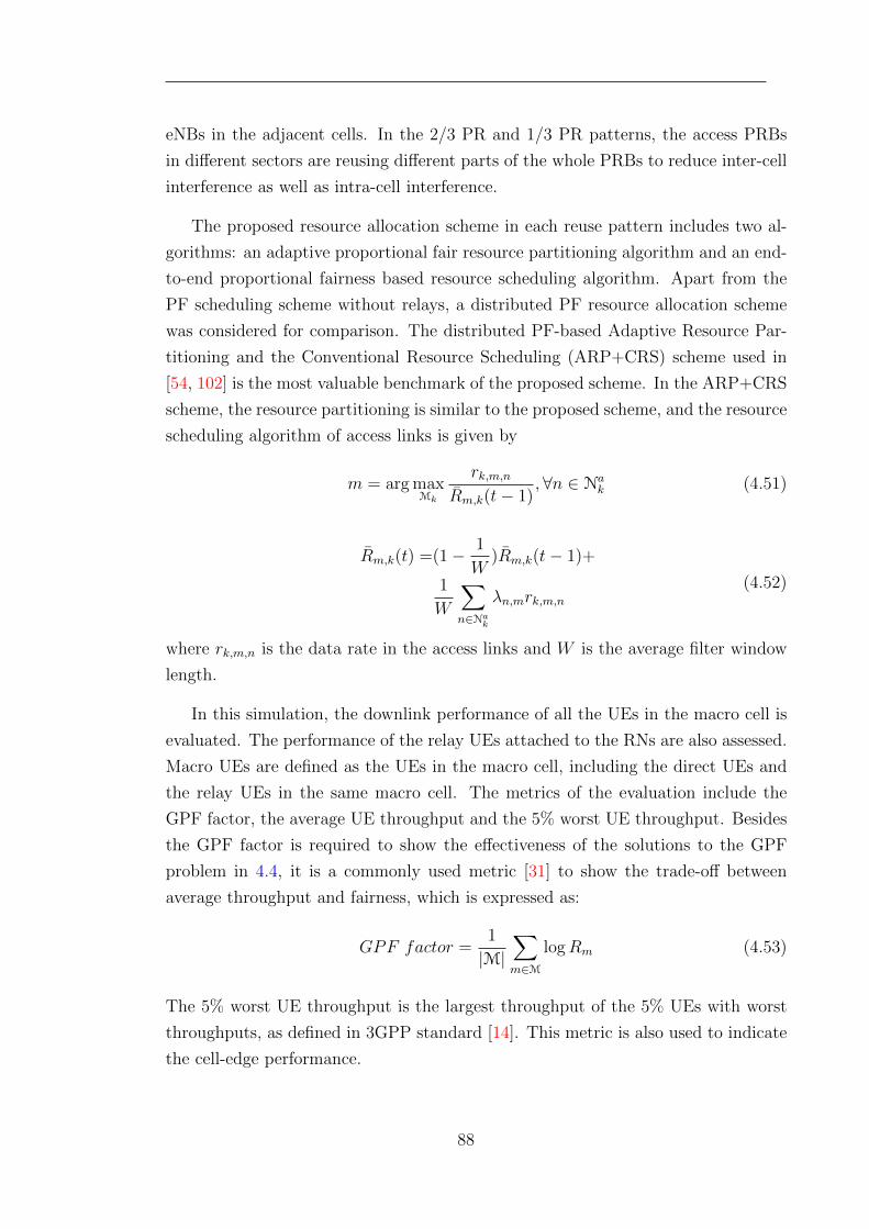
eNBs in the adjacent cells. In the 2/3 PR and 1/3 PR patterns, the access PRBs
in different sectors are reusing different parts of the whole PRBs to reduce inter-cell
interference as well as intra-cell interference.
The proposed resource allocation scheme in each reuse pattern includes two al-
gorithms: an adaptive proportional fair resource partitioning algorithm and an end-
to-end proportional fairness based resource scheduling algorithm. Apart from the
PF scheduling scheme without relays, a distributed PF resource allocation scheme
was considered for comparison. The distributed PF-based Adaptive Resource Par-
titioning and the Conventional Resource Scheduling (ARP+CRS) scheme used in
[54, 102] is the most valuable benchmark of the proposed scheme. In the ARP+CRS
scheme, the resource partitioning is similar to the proposed scheme, and the resource
scheduling algorithm of access links is given by
m = arg maxMk
rk,m,nRm,k(t− 1)
,∀n ∈ Nak (4.51)
Rm,k(t) =(1− 1
W)Rm,k(t− 1)+
1
W
∑n∈Na
k
λn,mrk,m,n(4.52)
where rk,m,n is the data rate in the access links and W is the average filter window
length.
In this simulation, the downlink performance of all the UEs in the macro cell is
evaluated. The performance of the relay UEs attached to the RNs are also assessed.
Macro UEs are defined as the UEs in the macro cell, including the direct UEs and
the relay UEs in the same macro cell. The metrics of the evaluation include the
GPF factor, the average UE throughput and the 5% worst UE throughput. Besides
the GPF factor is required to show the effectiveness of the solutions to the GPF
problem in 4.4, it is a commonly used metric [31] to show the trade-off between
average throughput and fairness, which is expressed as:
GPF factor =1
|M|∑m∈M
logRm (4.53)
The 5% worst UE throughput is the largest throughput of the 5% UEs with worst
throughputs, as defined in 3GPP standard [14]. This metric is also used to indicate
the cell-edge performance.
88
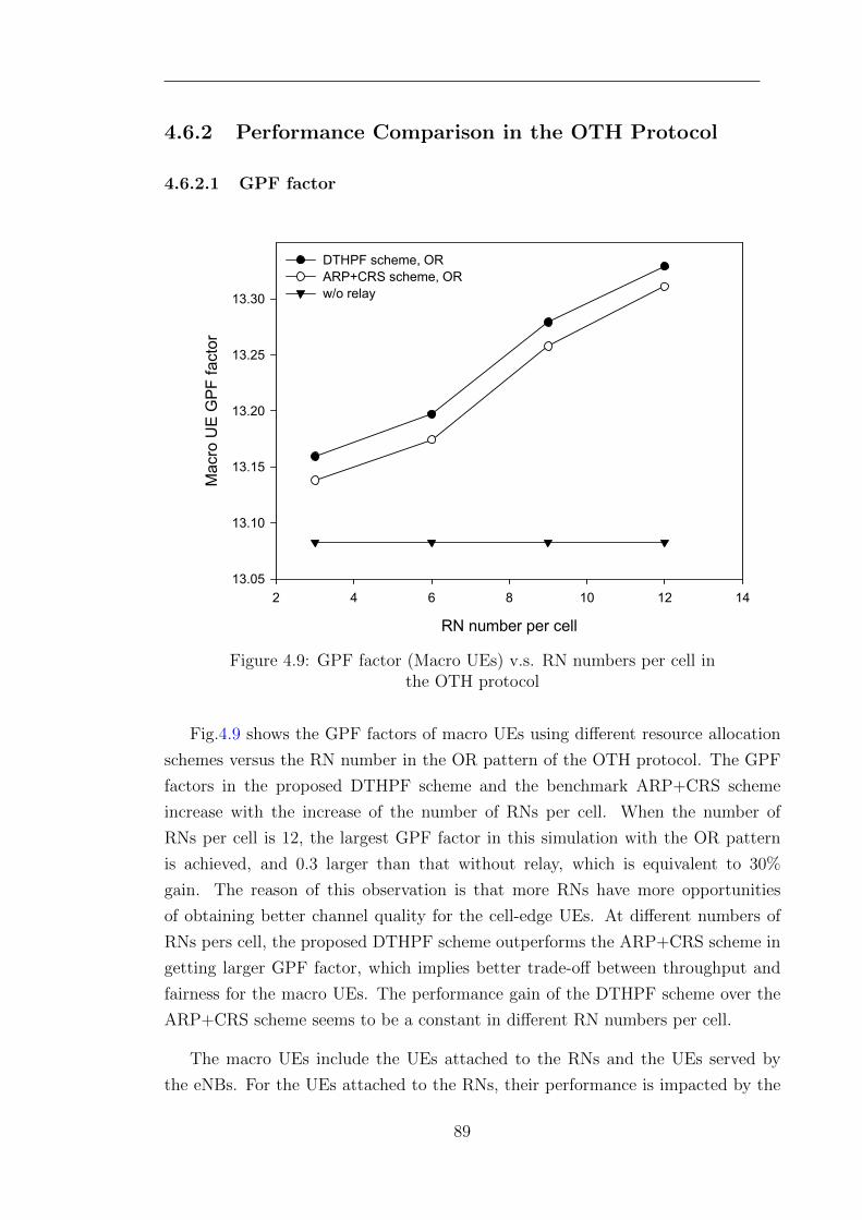
4.6.2 Performance Comparison in the OTH Protocol
4.6.2.1 GPF factor
RN number per cell
2 4 6 8 10 12 14
Mac
ro U
E G
PF
fac
tor
13.05
13.10
13.15
13.20
13.25
13.30
DTHPF scheme, ORARP+CRS scheme, ORw/o relay
Figure 4.9: GPF factor (Macro UEs) v.s. RN numbers per cell inthe OTH protocol
Fig.4.9 shows the GPF factors of macro UEs using different resource allocation
schemes versus the RN number in the OR pattern of the OTH protocol. The GPF
factors in the proposed DTHPF scheme and the benchmark ARP+CRS scheme
increase with the increase of the number of RNs per cell. When the number of
RNs per cell is 12, the largest GPF factor in this simulation with the OR pattern
is achieved, and 0.3 larger than that without relay, which is equivalent to 30%
gain. The reason of this observation is that more RNs have more opportunities
of obtaining better channel quality for the cell-edge UEs. At different numbers of
RNs pers cell, the proposed DTHPF scheme outperforms the ARP+CRS scheme in
getting larger GPF factor, which implies better trade-off between throughput and
fairness for the macro UEs. The performance gain of the DTHPF scheme over the
ARP+CRS scheme seems to be a constant in different RN numbers per cell.
The macro UEs include the UEs attached to the RNs and the UEs served by
the eNBs. For the UEs attached to the RNs, their performance is impacted by the
89
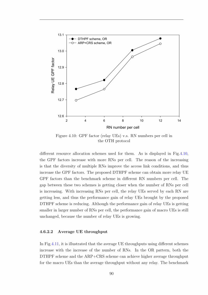
RN number per cell
2 4 6 8 10 12 14
Rel
ay U
E G
PF
fac
tor
12.6
12.7
12.8
12.9
13.0
13.1DTHPF scheme, ORARP+CRS scheme, OR
Figure 4.10: GPF factor (relay UEs) v.s. RN numbers per cell inthe OTH protocol
different resource allocation schemes used for them. As is displayed in Fig.4.10,
the GPF factors increase with more RNs per cell. The reason of the increasing
is that the diversity of multiple RNs improve the access link conditions, and thus
increase the GPF factors. The proposed DTHPF scheme can obtain more relay UE
GPF factors than the benchmark scheme in different RN numbers per cell. The
gap between these two schemes is getting closer when the number of RNs per cell
is increasing. With increasing RNs per cell, the relay UEs served by each RN are
getting less, and thus the performance gain of relay UEs brought by the proposed
DTHPF scheme is reducing. Although the performance gain of relay UEs is getting
smaller in larger number of RNs per cell, the performance gain of macro UEs is still
unchanged, because the number of relay UEs is growing.
4.6.2.2 Average UE throughput
In Fig.4.11, it is illustrated that the average UE throughputs using different schemes
increase with the increase of the number of RNs. In the OR pattern, both the
DTHPF scheme and the ARP+CRS scheme can achieve higher average throughput
for the macro UEs than the average throughput without any relay. The benchmark
90
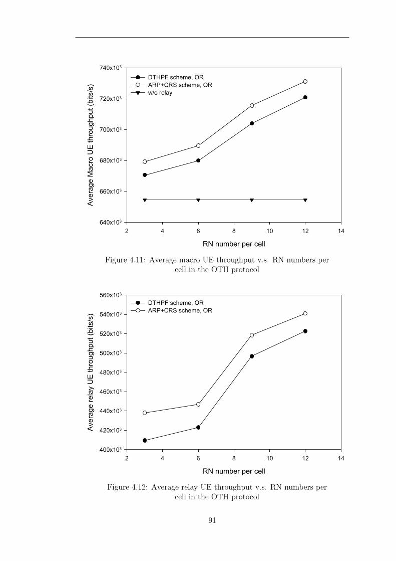
RN number per cell
2 4 6 8 10 12 14
Ave
rage
Mac
ro U
E th
roug
hput
(bi
ts/s
)
640x103
660x103
680x103
700x103
720x103
740x103
DTHPF scheme, ORARP+CRS scheme, ORw/o relay
Figure 4.11: Average macro UE throughput v.s. RN numbers percell in the OTH protocol
RN number per cell
2 4 6 8 10 12 14
Ave
rage
rel
ay U
E th
roug
hput
(bi
ts/s
)
400x103
420x103
440x103
460x103
480x103
500x103
520x103
540x103
560x103
DTHPF scheme, ORARP+CRS scheme, OR
Figure 4.12: Average relay UE throughput v.s. RN numbers percell in the OTH protocol
91
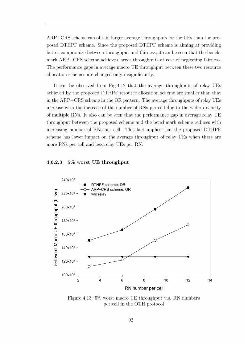
ARP+CRS scheme can obtain larger average throughputs for the UEs than the pro-
posed DTHPF scheme. Since the proposed DTHPF scheme is aiming at providing
better compromise between throughput and fairness, it can be seen that the bench-
mark ARP+CRS scheme achieves larger throughputs at cost of neglecting fairness.
The performance gaps in average macro UE throughput between these two resource
allocation schemes are changed only insignificantly.
It can be observed from Fig.4.12 that the average throughputs of relay UEs
achieved by the proposed DTHPF resource allocation scheme are smaller than that
in the ARP+CRS scheme in the OR pattern. The average throughputs of relay UEs
increase with the increase of the number of RNs per cell due to the wider diversity
of multiple RNs. It also can be seen that the performance gap in average relay UE
throughput between the proposed scheme and the benchmark scheme reduces with
increasing number of RNs per cell. This fact implies that the proposed DTHPF
scheme has lower impact on the average throughput of relay UEs when there are
more RNs per cell and less relay UEs per RN.
4.6.2.3 5% worst UE throughput
RN number per cell
2 4 6 8 10 12 14
5% w
orst
Mac
ro U
E th
roug
hput
(bi
ts/s
)
100x103
120x103
140x103
160x103
180x103
200x103
220x103
240x103
DTHPF scheme, ORARP+CRS scheme, ORw/o relay
Figure 4.13: 5% worst macro UE throughput v.s. RN numbersper cell in the OTH protocol
92
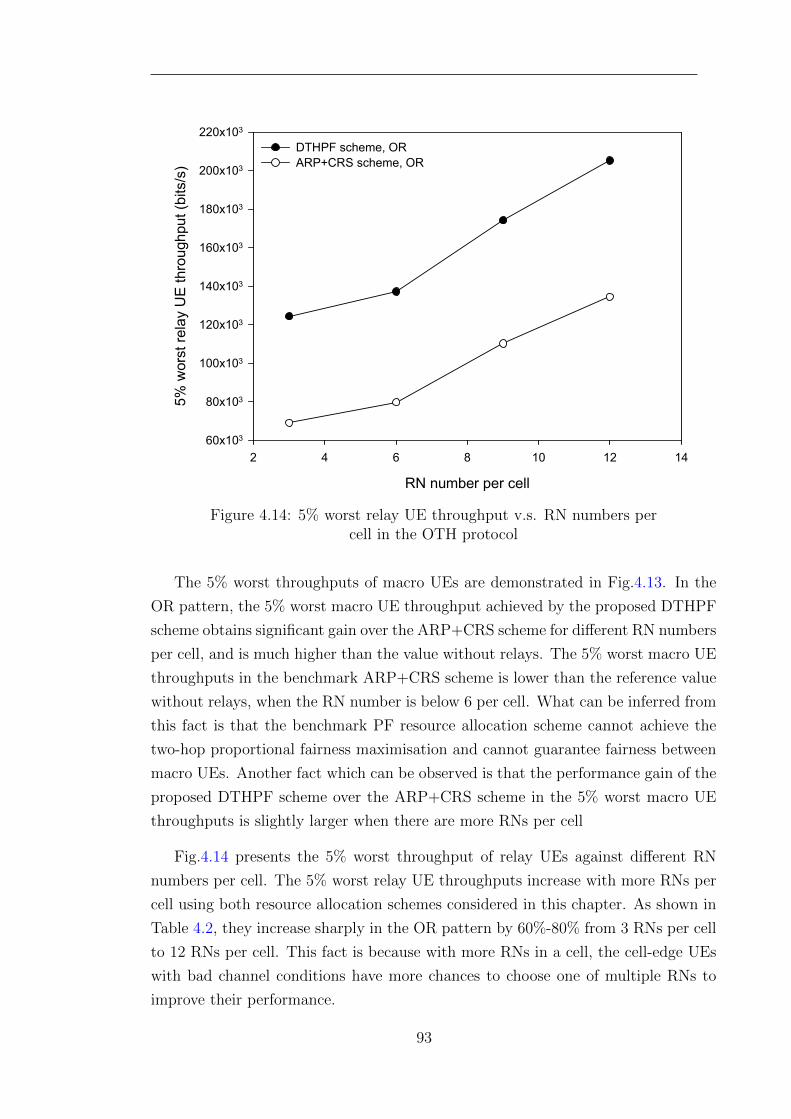
RN number per cell
2 4 6 8 10 12 14
5% w
orst
rel
ay U
E th
roug
hput
(bi
ts/s
)
60x103
80x103
100x103
120x103
140x103
160x103
180x103
200x103
220x103
DTHPF scheme, ORARP+CRS scheme, OR
Figure 4.14: 5% worst relay UE throughput v.s. RN numbers percell in the OTH protocol
The 5% worst throughputs of macro UEs are demonstrated in Fig.4.13. In the
OR pattern, the 5% worst macro UE throughput achieved by the proposed DTHPF
scheme obtains significant gain over the ARP+CRS scheme for different RN numbers
per cell, and is much higher than the value without relays. The 5% worst macro UE
throughputs in the benchmark ARP+CRS scheme is lower than the reference value
without relays, when the RN number is below 6 per cell. What can be inferred from
this fact is that the benchmark PF resource allocation scheme cannot achieve the
two-hop proportional fairness maximisation and cannot guarantee fairness between
macro UEs. Another fact which can be observed is that the performance gain of the
proposed DTHPF scheme over the ARP+CRS scheme in the 5% worst macro UE
throughputs is slightly larger when there are more RNs per cell
Fig.4.14 presents the 5% worst throughput of relay UEs against different RN
numbers per cell. The 5% worst relay UE throughputs increase with more RNs per
cell using both resource allocation schemes considered in this chapter. As shown in
Table 4.2, they increase sharply in the OR pattern by 60%-80% from 3 RNs per cell
to 12 RNs per cell. This fact is because with more RNs in a cell, the cell-edge UEs
with bad channel conditions have more chances to choose one of multiple RNs to
improve their performance.
93
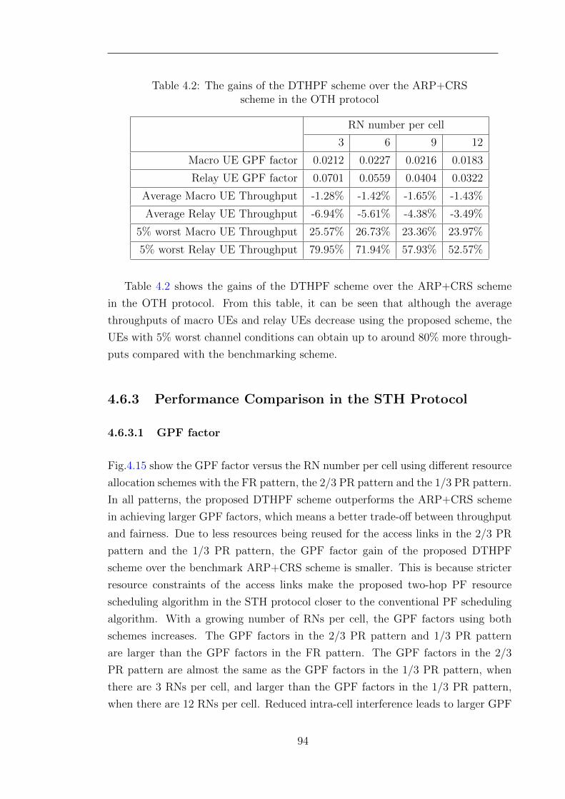
Table 4.2: The gains of the DTHPF scheme over the ARP+CRSscheme in the OTH protocol
RN number per cell
3 6 9 12
Macro UE GPF factor 0.0212 0.0227 0.0216 0.0183
Relay UE GPF factor 0.0701 0.0559 0.0404 0.0322
Average Macro UE Throughput -1.28% -1.42% -1.65% -1.43%
Average Relay UE Throughput -6.94% -5.61% -4.38% -3.49%
5% worst Macro UE Throughput 25.57% 26.73% 23.36% 23.97%
5% worst Relay UE Throughput 79.95% 71.94% 57.93% 52.57%
Table 4.2 shows the gains of the DTHPF scheme over the ARP+CRS scheme
in the OTH protocol. From this table, it can be seen that although the average
throughputs of macro UEs and relay UEs decrease using the proposed scheme, the
UEs with 5% worst channel conditions can obtain up to around 80% more through-
puts compared with the benchmarking scheme.
4.6.3 Performance Comparison in the STH Protocol
4.6.3.1 GPF factor
Fig.4.15 show the GPF factor versus the RN number per cell using different resource
allocation schemes with the FR pattern, the 2/3 PR pattern and the 1/3 PR pattern.
In all patterns, the proposed DTHPF scheme outperforms the ARP+CRS scheme
in achieving larger GPF factors, which means a better trade-off between throughput
and fairness. Due to less resources being reused for the access links in the 2/3 PR
pattern and the 1/3 PR pattern, the GPF factor gain of the proposed DTHPF
scheme over the benchmark ARP+CRS scheme is smaller. This is because stricter
resource constraints of the access links make the proposed two-hop PF resource
scheduling algorithm in the STH protocol closer to the conventional PF scheduling
algorithm. With a growing number of RNs per cell, the GPF factors using both
schemes increases. The GPF factors in the 2/3 PR pattern and 1/3 PR pattern
are larger than the GPF factors in the FR pattern. The GPF factors in the 2/3
PR pattern are almost the same as the GPF factors in the 1/3 PR pattern, when
there are 3 RNs per cell, and larger than the GPF factors in the 1/3 PR pattern,
when there are 12 RNs per cell. Reduced intra-cell interference leads to larger GPF
94
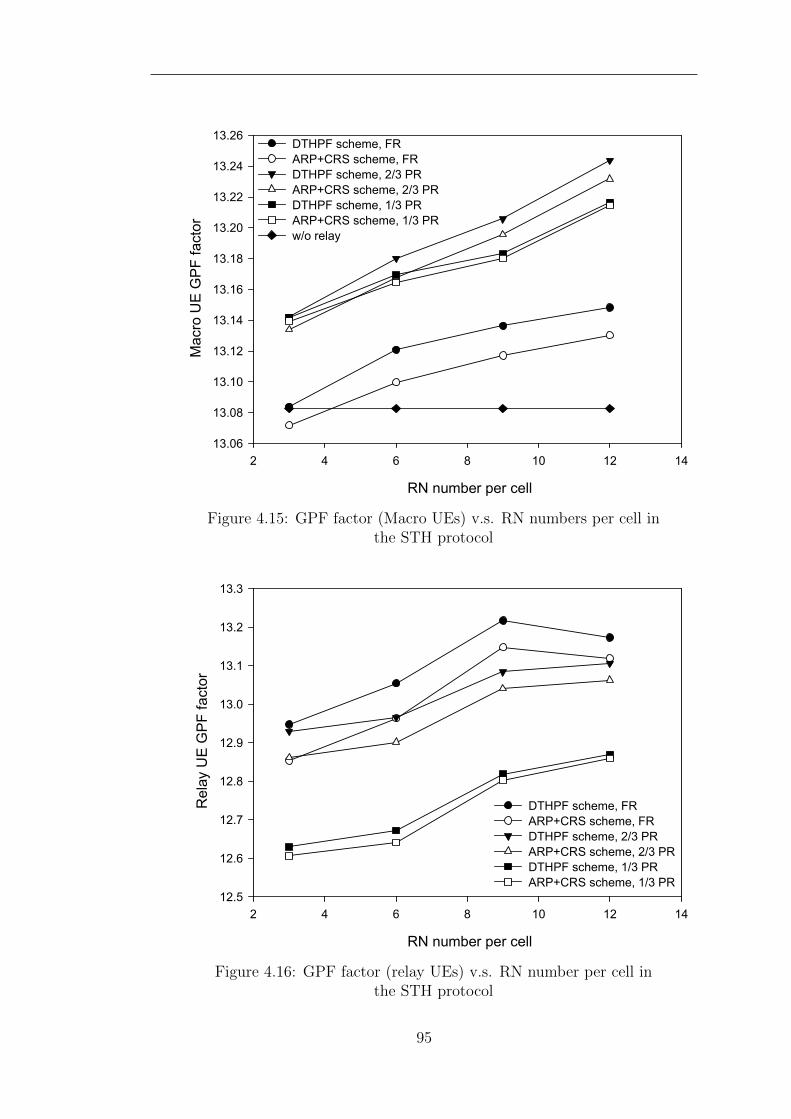
RN number per cell
2 4 6 8 10 12 14
Mac
ro U
E G
PF
fac
tor
13.06
13.08
13.10
13.12
13.14
13.16
13.18
13.20
13.22
13.24
13.26DTHPF scheme, FRARP+CRS scheme, FRDTHPF scheme, 2/3 PRARP+CRS scheme, 2/3 PRDTHPF scheme, 1/3 PRARP+CRS scheme, 1/3 PRw/o relay
Figure 4.15: GPF factor (Macro UEs) v.s. RN numbers per cell inthe STH protocol
RN number per cell
2 4 6 8 10 12 14
Rel
ay U
E G
PF
fac
tor
12.5
12.6
12.7
12.8
12.9
13.0
13.1
13.2
13.3
DTHPF scheme, FRARP+CRS scheme, FRDTHPF scheme, 2/3 PRARP+CRS scheme, 2/3 PRDTHPF scheme, 1/3 PRARP+CRS scheme, 1/3 PR
Figure 4.16: GPF factor (relay UEs) v.s. RN number per cell inthe STH protocol
95
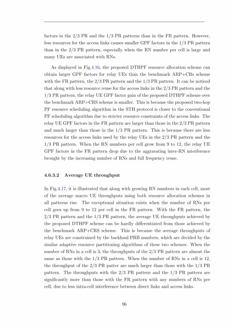
factors in the 2/3 PR and the 1/3 PR patterns than in the FR pattern. However,
less resources for the access links causes smaller GPF factors in the 1/3 PR pattern
than in the 2/3 PR pattern, especially when the RN number per cell is large and
many UEs are associated with RNs.
As displayed in Fig.4.16, the proposed DTHPF resource allocation scheme can
obtain larger GPF factors for relay UEs than the benchmark ARP+CRs scheme
with the FR pattern, the 2/3 PR pattern and the 1/3 PR pattern. It can be noticed
that along with less resource reuse for the access links in the 2/3 PR pattern and the
1/3 PR pattern, the relay UE GPF factor gain of the proposed DTHPF scheme over
the benchmark ARP+CRS scheme is smaller. This is because the proposed two-hop
PF resource scheduling algorithm in the STH protocol is closer to the conventional
PF scheduling algorithm due to stricter resource constraints of the access links. The
relay UE GPF factors in the FR pattern are larger than those in the 2/3 PR pattern
and much larger than those in the 1/3 PR pattern. This is because there are less
resources for the access links used by the relay UEs in the 2/3 PR pattern and the
1/3 PR pattern. When the RN numbers per cell grow from 9 to 12, the relay UE
GPF factors in the FR pattern drop due to the aggravating inter-RN interference
brought by the increasing number of RNs and full frequency reuse.
4.6.3.2 Average UE throughput
In Fig.4.17, it is illustrated that along with growing RN numbers in each cell, most
of the average macro UE throughputs using both resource allocation schemes in
all patterns rise. The exceptional situation exists when the number of RNs per
cell goes up from 9 to 12 per cell in the FR pattern. With the FR pattern, the
2/3 PR pattern and the 1/3 PR pattern, the average UE throughputs achieved by
the proposed DTHPF scheme can be hardly differentiated from those achieved by
the benchmark ARP+CRS scheme. This is because the average throughputs of
relay UEs are constrained by the backhaul PRB numbers, which are decided by the
similar adaptive resource partitioning algorithms of these two schemes. When the
number of RNs in a cell is 3, the throughputs of the 2/3 PR pattern are almost the
same as those with the 1/3 PR pattern. When the number of RNs in a cell is 12,
the throughput of the 2/3 PR patter are much larger than those with the 1/3 PR
pattern. The throughputs with the 2/3 PR pattern and the 1/3 PR pattern are
significantly more than those with the FR pattern with any numbers of RNs per
cell, due to less intra-cell interference between direct links and access links.
96
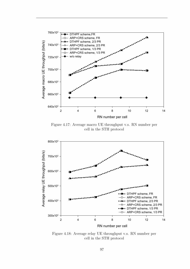
RN number per cell
2 4 6 8 10 12 14
Ave
rage
mac
ro U
E th
roug
hput
(bi
ts/s
)
640x103
660x103
680x103
700x103
720x103
740x103
760x103
DTHPF scheme,FRARP+CRS scheme, FRDTHPF scheme, 2/3 PRARP+CRS scheme, 2/3 PRDTHPF scheme, 1/3 PRARP+CRS scheme, 1/3 PRw/o relay
Figure 4.17: Average macro UE throughput v.s. RN number percell in the STH protocol
RN number per cell
2 4 6 8 10 12 14
Ave
rage
rel
ay U
E th
roug
hput
(bi
ts/s
)
300x103
400x103
500x103
600x103
700x103
800x103
DTHPF scheme, FRARP+CRS scheme, FRDTHPF scheme, 2/3 PRARP+CRS scheme, 2/3 PRDTHPF scheme, 1/3 PRARP+CRS scheme, 1/3 PR
Figure 4.18: Average relay UE throughput v.s. RN number percell in the STH protocol
97
From Fig.4.18, the average relay UE throughputs achieved by the proposed
DTHPF scheme and the ARP+CRS scheme with the FR pattern, the 2/3 PR pat-
tern and the 1/3 PR pattern can be observed. Due to similar reasons, the average
relay UE throughputs achieved by the proposed DTHPF scheme and the benchmark
ARP+CRS scheme in all patterns are almost identical. The average throughputs of
relay UEs in the FR pattern are larger than those with the 2/3 PR pattern. The
average throughputs of relay UEs in the FR and the 2/3 PR patterns are larger than
those with the 1/3 PR pattern. Their relationship is proportional to the amount of
resources assigned to the relay UE in the access links. When the RN number per
cell goes up from 9 to 12, the average relay UE throughputs in the FR pattern falls,
because of increasing interference between multiple RNs.
4.6.3.3 5% worst UE throughput
RN number per cell
2 4 6 8 10 12 14
5% w
orst
mac
ro U
E th
roug
hput
(bi
ts/s
)
100x103
110x103
120x103
130x103
140x103
150x103
160x103
170x103
DTHPF scheme, FRARP+CRS scheme, FRDTHPF scheme, 2/3 PRARP+CRS scheme, 2/3 PRDTHPF scheme, 1/3 PRARP+CRS scheme, 1/3 PRw/o relay
Figure 4.19: 5% worst macro UE throughput v.s. RN number percell in the STH protocol
The 5% worst throughputs of macro UEs are demonstrated in Fig.4.19. In the
FR pattern, the 5% worst throughputs are less than those without relays in different
RN numbers per cell, and the proposed scheme performs better than the ARP+CRS
scheme. The reason of this situation is that all the UEs in the macro cell are fully
98
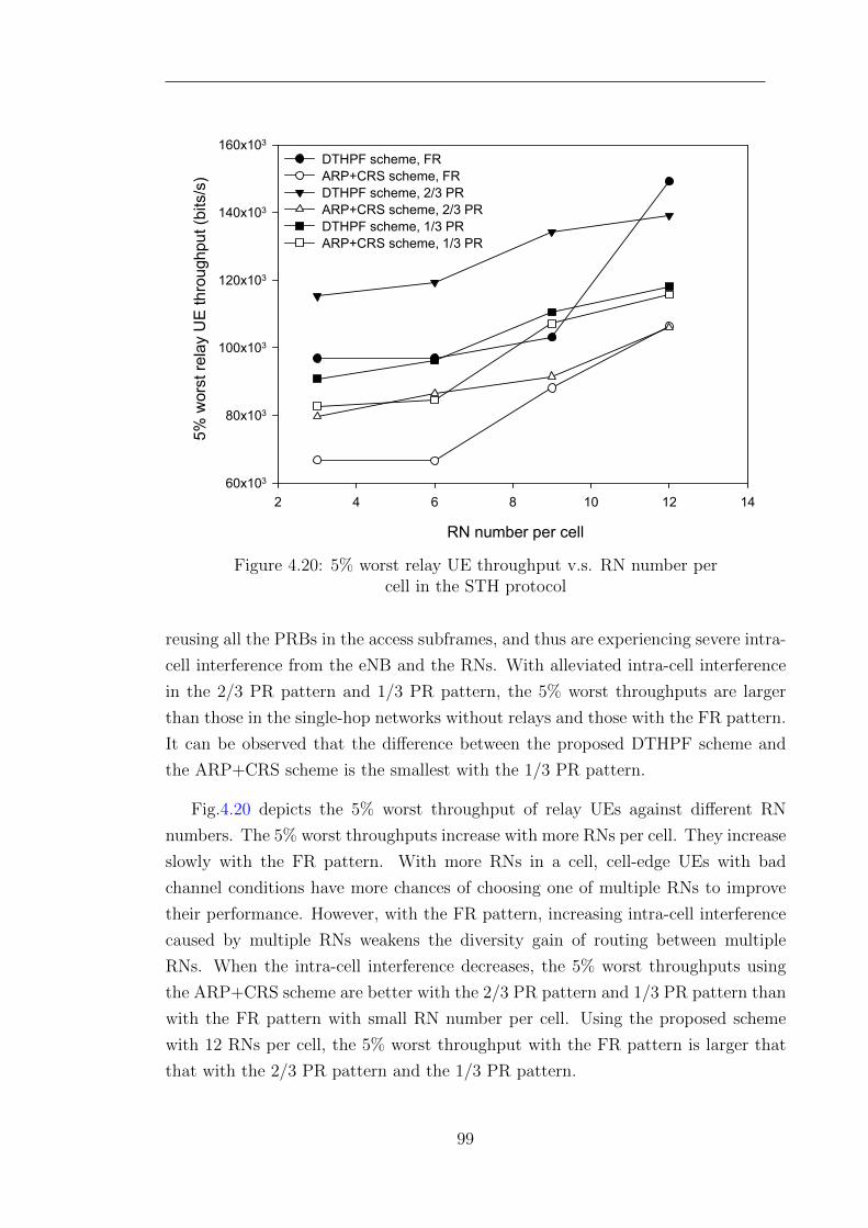
RN number per cell
2 4 6 8 10 12 14
5% w
orst
rel
ay U
E th
roug
hput
(bi
ts/s
)
60x103
80x103
100x103
120x103
140x103
160x103
DTHPF scheme, FRARP+CRS scheme, FRDTHPF scheme, 2/3 PRARP+CRS scheme, 2/3 PRDTHPF scheme, 1/3 PRARP+CRS scheme, 1/3 PR
Figure 4.20: 5% worst relay UE throughput v.s. RN number percell in the STH protocol
reusing all the PRBs in the access subframes, and thus are experiencing severe intra-
cell interference from the eNB and the RNs. With alleviated intra-cell interference
in the 2/3 PR pattern and 1/3 PR pattern, the 5% worst throughputs are larger
than those in the single-hop networks without relays and those with the FR pattern.
It can be observed that the difference between the proposed DTHPF scheme and
the ARP+CRS scheme is the smallest with the 1/3 PR pattern.
Fig.4.20 depicts the 5% worst throughput of relay UEs against different RN
numbers. The 5% worst throughputs increase with more RNs per cell. They increase
slowly with the FR pattern. With more RNs in a cell, cell-edge UEs with bad
channel conditions have more chances of choosing one of multiple RNs to improve
their performance. However, with the FR pattern, increasing intra-cell interference
caused by multiple RNs weakens the diversity gain of routing between multiple
RNs. When the intra-cell interference decreases, the 5% worst throughputs using
the ARP+CRS scheme are better with the 2/3 PR pattern and 1/3 PR pattern than
with the FR pattern with small RN number per cell. Using the proposed scheme
with 12 RNs per cell, the 5% worst throughput with the FR pattern is larger that
that with the 2/3 PR pattern and the 1/3 PR pattern.
99
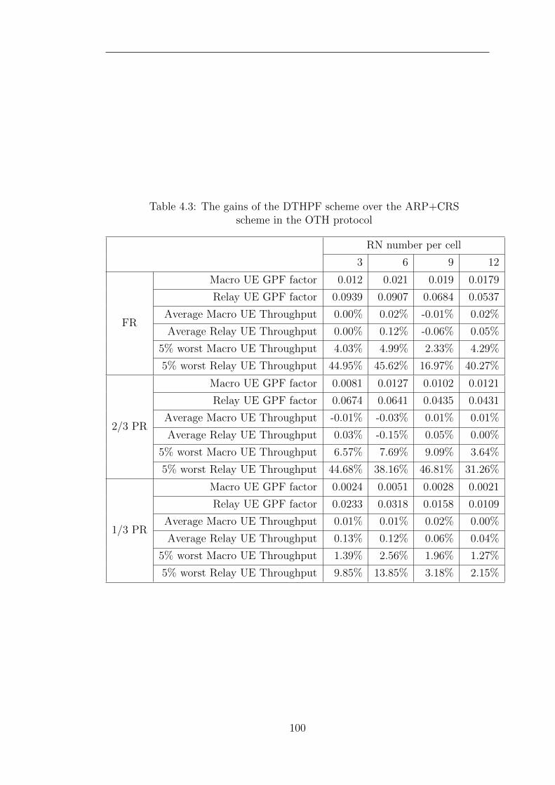
Table 4.3: The gains of the DTHPF scheme over the ARP+CRSscheme in the OTH protocol
RN number per cell
3 6 9 12
FR
Macro UE GPF factor 0.012 0.021 0.019 0.0179
Relay UE GPF factor 0.0939 0.0907 0.0684 0.0537
Average Macro UE Throughput 0.00% 0.02% -0.01% 0.02%
Average Relay UE Throughput 0.00% 0.12% -0.06% 0.05%
5% worst Macro UE Throughput 4.03% 4.99% 2.33% 4.29%
5% worst Relay UE Throughput 44.95% 45.62% 16.97% 40.27%
2/3 PR
Macro UE GPF factor 0.0081 0.0127 0.0102 0.0121
Relay UE GPF factor 0.0674 0.0641 0.0435 0.0431
Average Macro UE Throughput -0.01% -0.03% 0.01% 0.01%
Average Relay UE Throughput 0.03% -0.15% 0.05% 0.00%
5% worst Macro UE Throughput 6.57% 7.69% 9.09% 3.64%
5% worst Relay UE Throughput 44.68% 38.16% 46.81% 31.26%
1/3 PR
Macro UE GPF factor 0.0024 0.0051 0.0028 0.0021
Relay UE GPF factor 0.0233 0.0318 0.0158 0.0109
Average Macro UE Throughput 0.01% 0.01% 0.02% 0.00%
Average Relay UE Throughput 0.13% 0.12% 0.06% 0.04%
5% worst Macro UE Throughput 1.39% 2.56% 1.96% 1.27%
5% worst Relay UE Throughput 9.85% 13.85% 3.18% 2.15%
100
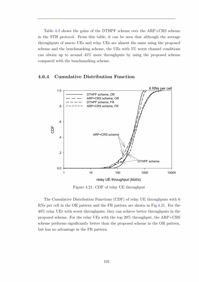
Table 4.3 shows the gains of the DTHPF scheme over the ARP+CRS scheme
in the STH protocol. From this table, it can be seen that although the average
throughputs of macro UEs and relay UEs are almost the same using the proposed
scheme and the benchmarking scheme, the UEs with 5% worst channel conditions
can obtain up to around 45% more throughputs by using the proposed scheme
compared with the benchmarking scheme.
4.6.4 Cumulative Distribution Function
6 RNs per cell
relay UE throughput (kbit/s)
1 10 100 1000 10000
CD
F
0.0
.2
.4
.6
.8
1.0DTHPF scheme, ORARP+CRS scheme, ORDTHPF scheme, FRARP+CRS scheme, FR
ARP+CRS scheme
DTHPF scheme
Figure 4.21: CDF of relay UE throughput
The Cumulative Distribution Functions (CDF) of relay UE throughputs with 6
RNs per cell in the OR pattern and the FR pattern are shown in Fig.4.21. For the
40% relay UEs with worst throughputs, they can achieve better throughputs in the
proposed scheme. For the relay UEs with the top 20% throughput, the ARP+CRS
scheme performs significantly better than the proposed scheme in the OR pattern,
but has no advantage in the FR pattern.
101
4.6.5 Summary
In summary, the proposed DTHPF resource allocation scheme has better GPF fac-
tors and better 5% worst UE throughputs, for different RN numbers in all the reuse
patterns. The performance of macro UEs with the OR pattern is better than that
with the FR pattern, because extra intra-cell interference is generated by reusing
the same PRB in direct links and access links with the FR pattern. However, the
performance of relay UEs is better with the FR pattern than with the OR pattern.
With less intra-cell interference and less resources for the access links with the 1/3
PR pattern, the performance is better than that for the FR pattern using the pro-
posed scheme and the benchmark scheme. The performance gain achieved by the
proposed DTHPF scheme compared to the benchmark ARP+CRS scheme is small.
As the compromise between the FR pattern and the 1/3 PR pattern, the 2/3 PR
pattern can achieve better performance and significant performance gain using the
proposed scheme.
Since the proposed DTHPF resource allocation scheme considers the channel
conditions of access links and backhaul links together, the UEs with bad channel
conditions can have more opportunities to occupy the resources partitioned for the
access links. Compared with the OTH protocol, the DTHPF resource allocation
scheme has worse performance of the UEs with bad channel conditions in the STH
protocol. This is because in the STH protocol, the two-hop resource scheduling is
constrained by the resource number of backhaul links.
The two-hop resource scheduling and the adaptive resource partitioning in the
proposed DTHPF resource allocation scheme will not request extra control channels
in backhaul links. The proposed two-hop resource scheduling at the RNs needs the
channel information of their backhaul links, which can be easily obtained and will
consume few computation resources of the RNs.
4.7 Conclusion
The existing distributed PF resource allocation schemes, using the conventional
single-hop PF scheduling algorithm at RNs, fail to ensure the two-hop end-to-end
proportional fairness of relay UEs. This chapter proposes a distributed two-hop
proportional fair (DTHPF) resource allocation scheme that can achieve better two-
hop end-to-end proportional fairness in LTE-Advanced networks with Type I relay
102
nodes. The contributions in this chapter are that the GPF problem is formulated and
decomposed into two related sub-problems, i.e., a resource partitioning sub-problem
and a resource scheduling sub-problem; orthogonal and simultaneous two-hop trans-
mission protocols are considered in solving the sub-problems; the existing adaptive
resource partitioning algorithms are adjusted for LTE-Advanced networks; and two
algorithms are proposed for two-hop resource scheduling subject to different resource
partitioning constraints. The simulation results show that the proposed DTHPF re-
source allocation schemes have achieved better compromise between throughput and
fairness.
103
Chapter 5
Two-Hop Adaptive Partial
Frequency Reusing
5.1 Introduction
In this chapter, two-hop adaptive partial frequency reusing (APFR) in relay en-
hanced LTE-Advanced networks is studied. In the LTE-Advanced standards on re-
lay node, access links of two-hop transmission are allowed to be allocated in the same
subframes with direct links. There are three possible relations between the access
links and the direct links. The time-frequency resources, i.e. PRBs, could be fully
reused, partially reused or orthogonally shared by the access links and direct links,
which can be marked as Full Frequency Reusing (FFR), Partial Frequency Reusing
(PFR) and None Frequency Reusing (NFR). When the resources are fully reused,
the maximum resources are utilised, but severe interference is generated; when the
resources are orthogonally shared, better spectral efficiency can be obtained with-
out interference, however the available resource numbers cannot increase. In order
to make a trade-off between increasing available resource numbers and alleviating
interference, PFR is considered for deciding a proper number of reused resources. In
LTE-Advanced two-hop networks, the resource numbers of access links and direct
links should be decided adaptively according to the number of relay UEs and direct
UEs. Therefore, APFR is considered to avoid load imbalance and guarantee the
fairness between relay UEs and direct UEs.
In what follows, the literature related to the method of determining the frequency
reusing and reducing interference in the reused resources are firstly reviewed. Then,
104
proportional fairness is used as the performance metric of APFR, which can make
an effective compromise between increasing throughput and guaranteeing fairness.
Thus, the APFR problem for maximising proportional fairness is formulated as a
Generalised Proportional Fairness (GPF) problem. After the route selection is deter-
mined for each UE, the GPF problem can be decomposed into a resource partitioning
problem. By solving the resource partitioning problem, a near-optimal result of the
reused PRB number for APFR can be achieved. In order to achieve better sys-
tem performance, a proportional fair joint route selection and resource partitioning
algorithm is proposed. Finally, the performance of the proposed APFR based al-
gorithm and the benchmarking FFR based algorithm are evaluated and compared.
The evaluation results show that the proposed APFR based algorithm can achieve
both larger throughput and better fairness with different RN transmitting power
and different RN distances than the benchmarking FFR based algorithm.
5.2 Related Work
Frequency reuse has been considered by many researchers in different approaches.
Different frequency reuse schemes are designed for maximising the system perfor-
mance with regard to different metrics. In the field of frequency reuse in two-hop
cellular networks, recent contributions are introduced and reviewed briefly.
Three inter-cell frequency planning schemes are proposed in [105] together with a
intra-cell resource partitioning solution. The proposed resource partitioning solution
is based on the numbers and the channel quality of the UEs in each kind of link. The
UE numbers are calculated according to the coverage of the eNB and the RN under
a uniform distribution of UEs. Through this solution, the whole frequency band is
orthogonally shared by the access links and the direct links in the same cell. For
inter-cell interference coordination, partial frequency reuse is utilised in the proposed
frequency planing schemes, including the cell partitioning based scheme, the virtual-
sector based scheme and the virtual-sector enhanced cell-partitioning based scheme.
Furthermore, more stringent constraints of resource partitioning are imposed by the
cell partitioning method for interference mitigation. The simulation results prove
their advantages in providing better performance with channel-dependent resource
partitioning. However, the same frequency band is reused in each cell, and the None
Frequency Reusing (NFR) is considered in the intra-cell resource partitioning.
In [106], a soft frequency reuse scheme based on power control is proposed in
105
order to mitigate the interference between adjacent sectors. Any sector can reuse
all the resources of the neighbouring sectors to achieve a frequency reuse factor of
1. The direct UEs and relay UEs share the resources orthogonally. Three sectors
in adjacent cells constitute a virtual cell. The transmitting power of eNBs and RNs
is adjusted to meet the Signal-to-Interference-Ratio (SIR)-balance principle in the
virtual cells. Besides, the resource allocation is based on the UE distribution and
their target throughput.
In [107], a modified fractional frequency partitioning scheme is proposed for inter-
cell interference coordination in relay enhanced cellular networks. Compared with
the traditional fractional frequency reuse scheme without relays, the resources for
the cell edge are assigned to the RNs. In order to maximise proportional fairness,
the numbers of the resources allocated to the eNB and the RNs are proportional
to the dynamic traffic load of the eNB and the RNs respectively. Both centralised
and distributed approaches are proposed to achieve load balancing. The proposed
scheme can provide better performance compared with the static resource partition-
ing. However, the frequency resources are not reused within the same cell.
Researches in [105, 106, 107] focus on applying adaptive partial frequency reuse
in inter-cell interference coordination.
Path selection rules with different frequency reuse patterns and frame transmis-
sion patterns are investigated in [53]. The proposed path selection rules in [53]
consider the spectral efficiencies of access links and backhaul links. When more
than two RNs are deployed and they are reusing the same resources, the effective
spectral efficiencies of access links are multiplied by the number of RNs and then
divided by the reuse factor. Simulation results not only provide an insight into the
appropriate RN distance, frequency reuse factors and frame transmission patterns,
but also prove that the proposed path selection rules are better than traditional
path selection rules. However, the calculation of effective spectral efficiency is based
on an equal UE distribution and static resource partitioning.
In [108], the spectral efficiency in the downlink of cellular relay networks is
analysed with opportunistic scheduling and spectrum reuse. The analysed spectral
efficiency is validated by a framework based on extreme-value theory and a system-
level simulation. Hence, this study provides an insight into the possible performance
enhancements from multi-hop transmission and frequency reuse with opportunistic
scheduling. The simulation results show that simultaneous transmission protocols
can achieve significantly better spectral efficiency than the orthogonal transmission
106
protocols. However, fair resource partitioning between eNB and RN is not consid-
ered. As the authors also suggest, relay-related frequency reuse policies should be
generalised by incorporating fractional frequency reuse techniques.
The problems of resource partitioning in orthogonal sharing and co-channel
reusing are considered in [109]. In both scenarios, one subframe is divided into
two equal time slots. The resource configuration scheme proposed in [109] is aimed
at achieving two principles. One is to ensure allocation fairness among the UEs
across the whole cell, not only the direct UEs served by the macro eNB but also
the relay UEs attached to the RNs. The other principle is to guarantee the same
throughput in the access links and corresponding backhaul links. By estimating the
coverage area of the macro eNB and the expectation values of SINR in different
positions, the system spectrum efficiency can be calculated. In the simulations, the
system performance is evaluated with different path loss factors and eNB coverage
areas along different RN positions. The co-channel reusing scenario is recommended
by the authors.
Paper [101] focuses on allocating resources between access links, backhaul links
and direct links in order to obtain a better compromise between fairness and through-
put. In this paper, the access links can reuse all the resources of direct links in the
backhaul subframes. The authors formulate the resource allocation problem as the
GPF problem. Aimed at achieving the GPF objective, i.e. maximising the sum
logarithmic UE data rate, the GPF resource allocation problem is divided into two
steps: resource partitioning and resource scheduling. This paper proposes an adap-
tive proportional fair resource partitioning algorithm. This algorithm calculates the
resources of backhaul links and direct links as directly proportional to the number
of UEs served by the eNB and the RNs, unless the resource numbers of access links
exceed the resource number of direct links. However, interference between access
links and direct links is not considered. Increasing the number of resources for the
access links will increase the interference of the direct links and thus decrease the
performance of direct UEs. In [102], a proportional fair based routing algorithm is
proposed jointly with an adaptive resource partitioning algorithm. The proposed
routing algorithm considers both the received signal quality and the number of re-
sources assigned to the UEs.
In [53, 101, 102, 108, 109], the performance with different intra-cell frequency
reuse scenarios is studied. The performance evaluations using full frequency reuse
and no frequency reuse have been given and their results are discussed. However,
intra-cell fractional frequency reuse is not investigated adequately.
107
[98] proposes a Load-Balancing Opportunistic (LoBO) scheduling algorithm that
improves the overall system throughput in a weighted proportional fairness manner.
At the same time, the traffic loads are balanced among the access links of all RNs.
The main contribution of [98] is the proposal of an effective subframe division algo-
rithm to determine the boundaries of access subframes and backhaul subframes as
part of opportunistic resource allocation. The concept of Resource Allocation Gap
(RAG) is introduced in order to represent the overall resource waste in the access
subframes. The RAG is used as the inverse weighting factor in the proportional
fair scheduling. In this way, the proposed LoBO scheduling algorithm is aimed at
reducing resource waste. A system evaluation demonstrates a 30% gain compared
with a conventional proportional fair scheduling algorithm in [17] with fixed sub-
frame division. Although adaptive resource reuse between the direct links and the
access links is considered, the intra-cell interference is not discussed or quantified.
The interference will influence the system performance significantly.
A low-complexity joint sub-carrier allocation, scheduling and power control scheme
is proposed in [71] by considering potential interference among neighbouring cells.
The joint resource allocation problem is solved by decomposing it into two stages.
In the first stage, subcarrier scheduling is conducted by a local search. In the second
stage, power is allocated for all of the scheduled subcarriers. By leveraging geomet-
ric programming, the authors prove that optimal power control can be achieved in
the high SIR region. Simulation results show that by utilizing the proposed joint
resource allocation scheme, the aggregated throughput of OFDMA-based relay net-
works can be improved. However, partial frequency reuse is not considered.
In [110], an optimal two-hop resource allocation scheme is proposed in order to
maximise the system throughput under max-min fairness constraints. This scheme
is compared with two well-known schemes [108], the orthogonal two-hop scheme and
the overlapped two-hop scheme. The authors formulate the optimisation problem
for each scheme, and solve it by using linear programming. The results show that
high cell throughput can be achieved by the proposed optimal scheme, while guar-
anteeing fairness and low outages. However, the complexity of the proposed scheme
is higher than the benchmarking schemes in [108], and route selection and resource
partitioning are not considered.
In [78], a time-domain resource scheduling algorithm with reuse in access sub-
frames is proposed. Based on the proposed scheduling algorithm without reuse,
subsets of UEs containing at most one of the UEs associated with each RNs are
considered. Then, the UE relay hop weighted flow is translated into an equivalent
108
weighted flow of the subsets for reuse. Hence, the scheduling problem with reuse is
transformed into a generic scheduling problem without reuse. Further, in the down-
link, the authors consider subsets of RNs instead of the subsets of UEs in order to
get a low- complexity scheduling algorithm. The algorithms in this paper should be
run for many iterations, and the scenario that the access links and the direct links
are reusing the same resources is not considered.
[111] addresses the problem of interference coordination in relay-aided cellular
OFDMA systems, aimed at exploiting the benefits of RNs while alleviating interfer-
ence. The authors propose an Integrated Interference Coordination Scheme (IICS)
for relay enhanced OFDMA systems. The IICS is composed of two phases. Each
of the two phases executes a specific resource assignment algorithm, namely Semi-
Static Allocation Algorithm (SSAA) and Dynamic Allocation Algorithm (DAA).
When the offered load is not very heavy, the low-complexity SSAA is used to allo-
cate orthogonal resources to UEs served by the eNB and the RNs. When the traffic
load is heavy, DAA is used for more efficient resource scheduling and more resource
reuse. The basic idea of SSAA is to guarantee one resource block for each UE, and
to allocate more resources to the UEs with low interference level. The DAA assigns
the UEs to individual clusters using a graph method. The UEs in a cluster can reuse
the same resource blocks with low interference. The resource blocks can by utilised
more efficiently by the DAA. The simulation results show that the proposed IICS
scheme can obtain improved system throughputs compared with resource allocation
schemes without adequate interference coordination.
In [112], a Pre-Configuration Algorithm (PCA) is added to the SSAA and DAA
to form a resource allocation with interference coordination scheme. PCA is used
when the traffic load is light and there are enough orthogonal resource blocks for
the UEs. The interference level can be reduced by PCA.
[113] proposes a game-theoretic framework called the Interference Coordination
Game (ICG) in order to further address the same problem in [111] and [112]. The
ICG is decomposed into two sub-games, the Resource Block Assignment Game
(RBAG) and the Power Allocation Game (PAG). RBAG allocates resource blocks
with alleviated interference. Furthermore, PAG is based on resource block assign-
ment for further reducing interference and improving system pay-off. In [113], the
existence and uniqueness of a Nash Equilibrium in ICG is proven. Simulation re-
sults show that the proposed framework can guarantee the Nash Equilibrium of
ICG. Compared with the fractional reuse scheme and the scheme without interfer-
ence coordination, better SINR and higher system throughput can be achieved.
109
In [71, 78, 98, 110, 111, 112, 113], centralised resource allocation algorithms are
proposed in order to achieve better performance under the adaptive partial frequency
reuse. However, these algorithms require many iterations and have high complexity.
In [88], the access links fully reuse the resources of direct links in the access
subframes. In the backhaul subframes, the resources used by the direct links and
backhaul links are orthogonal. The direct UEs with the worst channel quality may
be scheduled in the backhaul subframes in order to avoid severe interference from
the RNs. However, it can reduce the reuse efficiency and potentially decrease the
system throughput. In this paper, the authors propose a simple resource partitioning
algorithm to maximise the throughput while guaranteeing the minimum throughput
for each UE. However, the degree of interference between direct links and access links
is not considered in the resource partitioning problem. In addition, the routing
problem affected by the proposed resource partitioning algorithm is not studied.
The authors in [114] propose an interference coordination strategy to mitigate
the intra-cell co-channel interference between the RNs and the eNB. The concept of
an interference zone is introduced in this paper. In the interference zones, the inter-
ference level from some serving nodes is within a small range from the received signal
level. Otherwise, the UEs are in the non-interference zone. Based on the centralised
approach, two variants of resource partitioning algorithm are considered. In Variant
I, the fractional frequency reuse method is used. Using this method, the UEs in the
interference zones are assigned orthogonal resources. In Variant II, the resources for
the interference zones are reused by the UEs in the non-interference zone. The num-
ber of resources assigned to the interference zones and the non-interference zones are
determined by a per-zone resource partitioning algorithm based on the UE numbers.
In [115], the resource partitioning problem for fractional frequency reuse, i.e.
PFR, is studied. A Cell-colouring based Distributed Frequency Allocation (C-DFA)
method is described. The C-DFA in cellular networks can easily turn the resource
partitioning problem based on PFR in relay enhanced cellular networks into a dis-
tributed scheme without considering inter-cell interference. To validate the C-DFA,
a Dynamic Fractional Frequency Allocation (DDFFA) algorithm is proposed for the
relay enhanced OFDMA networks with two steps, channel grouping and channel
borrowing. Simulation results show that better system throughput can be achieved
by the DDFFA algorithm. The limitation of C-DFA and DDFFA is also discussed.
The distributed planar graph colouring algorithm cannot guarantee different colours
for neighbouring cells. Thus, severe inter-cell interference may happen to force the
DDFFA to increase computation and inter-node signal exchange.
110
In [116] and [117], a new frequency reuse scheme for heterogeneous networks
is proposed in addition a non-reuse scheme, a full-reuse scheme and a partial-reuse
scheme. The UEs which have low or medium SINR and experience main interference
from intra cell are indicated as the reserved UEs. Some resources are allocated to
these UEs in proportion to the number of UEs without reuse. The remaining UEs
can reuse the same resources. Using the frequency reservation method, the intra-
cell interference can be reduced by 50% in theory. The simulation results show
that better system capacity and cell-edge SINR can be achieved with this scheme.
However, fairness between UEs in the macro cell is not considered and an effective
compromise between throughput and fairness cannot be guaranteed.
In [118], a novel fractional frequency reuse scheme, i.e. PFR, is proposed based
on a no frequency reuse (NFR) scheme with interference coordination. In the NFR
scheme similar to [106], the eNB and the RNs in the same sector share the whole
frequency band, and the RNs in adjacent sectors use different frequency bands. In
the PFR scheme, the eNB can reuse part of the resources assigned to the RNs to
obtain more resources for direct links. Based on the proposed PFR scheme, a load
balancing algorithm is proposed. When the eNB is overloaded, some direct UEs can
reuse part of the resources assigned to the relay UEs with lower transmitting power.
When the RNs are overloaded, some relay UEs are handed over to the eNB in the
same cell. Moreover, the scheduling algorithm is revised to ensure the outer zone
UEs have priority to obtain resources.
In [119], a novel two-hop frequency reuse method is discussed with proportional
fairness consideration and cooperative relaying. Some resources are reused by the
eNB and the RNs for cooperative transmission to some UEs. Cooperative transmis-
sion can improve the spectral efficiency, which can be considered as another form
of increasing the number of resources. The RNs need to decide whether their UEs
are served independently or cooperatively with the eNB. The authors formulate the
resource allocation problem as an optimisation problem. By solving this problem,
an asymptotically optimal solution is derived to allocate resources among the co-
operative transmission UEs and the UEs independently served by the eNB and the
RNs. However, this paper doesn’t provide a method of determining the cooperative
UEs.
In [114, 115, 116, 117, 118, 119], the adaptive partial frequency reuse is realised by
deciding which UEs can occupy reused resources and which UEs can use non-reused
resources. The methods of determination are the interference-zone in [114], the
channel grouping and borrowing in [115, 118], the frequency reservation in [116, 117]
111
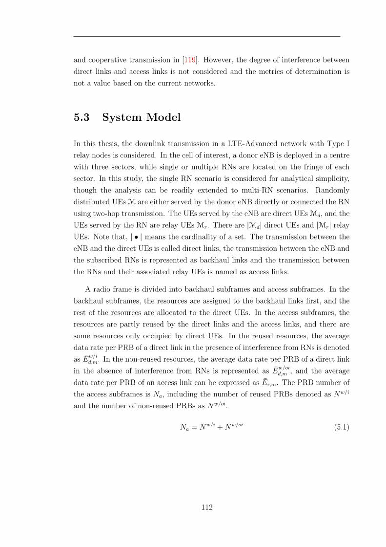
and cooperative transmission in [119]. However, the degree of interference between
direct links and access links is not considered and the metrics of determination is
not a value based on the current networks.
5.3 System Model
In this thesis, the downlink transmission in a LTE-Advanced network with Type I
relay nodes is considered. In the cell of interest, a donor eNB is deployed in a centre
with three sectors, while single or multiple RNs are located on the fringe of each
sector. In this study, the single RN scenario is considered for analytical simplicity,
though the analysis can be readily extended to multi-RN scenarios. Randomly
distributed UEs M are either served by the donor eNB directly or connected the RN
using two-hop transmission. The UEs served by the eNB are direct UEs Md, and the
UEs served by the RN are relay UEs Mr. There are |Md| direct UEs and |Mr| relay
UEs. Note that, | • | means the cardinality of a set. The transmission between the
eNB and the direct UEs is called direct links, the transmission between the eNB and
the subscribed RNs is represented as backhaul links and the transmission between
the RNs and their associated relay UEs is named as access links.
A radio frame is divided into backhaul subframes and access subframes. In the
backhaul subframes, the resources are assigned to the backhaul links first, and the
rest of the resources are allocated to the direct UEs. In the access subframes, the
resources are partly reused by the direct links and the access links, and there are
some resources only occupied by direct UEs. In the reused resources, the average
data rate per PRB of a direct link in the presence of interference from RNs is denoted
as Ew/id,m. In the non-reused resources, the average data rate per PRB of a direct link
in the absence of interference from RNs is represented as Ew/oid,m , and the average
data rate per PRB of an access link can be expressed as Er,m. The PRB number of
the access subframes is Na, including the number of reused PRBs denoted as Nw/i
and the number of non-reused PRBs as Nw/oi.
Na = Nw/i +Nw/oi (5.1)
112
5.4 Generalised Proportional Fairness (GPF) Prob-
lem Formulation
In this thesis, how to maximise the proportional fairness with adaptive PFR (PF-
APFR) can be formulated as a generalised proportional fair (GPF) problem. The
objective of this GPF problem is to maximise the utility of the sum of the logarithmic
data rates as:
max∑
m∈Md∩Mr
logRm = max(∑m∈Md
logRd,m +∑m∈Mr
logRr,m) (5.2)
where Rd,m and Rr,m are denoted as the data rate of a direct UE and the data rate
of a relay UE.
By assuming that a Proportional Fair (PF) based scheduling algorithm is utilised
for direct UEs and relay UEs, each of them has a fixed scheduling gain over the
Round-Robin scheduling algorithm, according to the findings in [31, 58]. Therefore,
the data rates of UEs can be simplified into the values only related to the resource
number and the average spectral efficiency. Considering the reused resources and
the non-reused resources occupied by the direct UEs, the data rate of each direct
UE can be expressed as:
Rd,m = (Nw/oi
|Md|Ew/oid,m +
Nw/i
|Md|Ew/id,m)Gd(|Md|) (5.3)
where Gd(|Md|) indicates the gain of the PF scheduling algorithm over Round-Robin
scheduling algorithm, which is related to the number of the scheduled UEs; Ew/oid,m
and Nw/oi denote the average data rate per PRB without reusing and the non-reused
PRB number respectively; Ew/id,m and Nw/i represent the average data rate per reused
PRB and the number of reused PRBs separately. Since the relay UEs only occupy
reused resources, their data rates can be expressed as:
Rr,m =Nw/i
|Mr|Er,mGr(|Mr|) (5.4)
Since the data rates of relay UEs should also be transmitted in the backhaul links,
the backhaul PRB numbers used by these relay UEs can be calculated as:
N b =
∑m∈Mr
Rr,m
Er,0= Nw/i
∑m∈Mr
Er,m
|Mr|Er,0Gr(|Mr|) = Nw/iθ (5.5)
113
where Er,0 denotes the average data rate per PRB in the backhaul link between the
RN r and the donor eNB, and θ represents the backhaul-to-access ratio, which is
defined as
θ =
∑m∈Mr
Er,m
|Mr|Er,0Gr(|Mr|) (5.6)
By substituting (5.3) and (5.4) into (5.2), the GPF problem can be rewritten as:
max{|Mr| logNw/i +∑m∈Mr
logGr(|Mr|)Er,m|Mr|
+∑m∈Md
log(Nw/i +Nw/oiEw/id,m
Ew/oid,m
) +∑m∈Md
logGd(|Md|)Ew/oi
d,m
|Md|}
(5.7)
After all the UEs have selected their serving nodes, their average data rates
per PRB can be measured. Thus, the GPF problem can be transformed into the
problem of determining an optimal PRB number for each set of links. Since the sum
of PRBs for different usages is a constant value N , this is also a resource partitioning
problem. The resource partitioning problem for PF-APFR can be described as
maxU(Nw/i)
= max{|Mr| logNw/i +∑m∈Md
log(Nw/oi +Nw/iEw/id,m
Ew/oid,m
)}
s.t. Nw/i +Nw/oi +N b = N
(5.8)
5.5 Proportional Fair Joint Route Selection and
Resource Partitioning Algorithm for APFR
5.5.1 A Near-Optimal Resource Partitioning Algorithm
In order to solve the resource partitioning problem for PF-APFR, the method of
Lagrange multiplier is utilised. The Lagrange function of the problem (5.8) is given
114
as
L(Nw/i, Nw/oi, λ) =|Mr| logNw/i +∑m∈Md
log(Nw/oi +Nw/iEw/id,m
Ew/oid,m
)
+λ(Nw/i +Nw/oi +Nb −N)
=|Mr| logNw/i +∑m∈Md
log(Nw/oi +Nw/iEw/id,m
Ew/oid,m
)
+λ(Nw/i +Nw/oi +Nw/iθ −N)
(5.9)
The gradients of the Lagrange function with respect to Nw/i and Nw/oi can be
obtained respectively as
∂L(Nw/i, Nw/oi, λ)
∂Nw/i=|Mr|Nw/i
+∑m∈Md
Ew/id,m
Ew/oid,m
Nw/oi +Nw/iEw/id,m
Ew/oid,m
+ λ(1 + θ) (5.10)
∂L(Nw/i, Nw/oi, λ)
∂Nw/oi=
∑m∈Md
1
Nw/oi +Nw/iEw/id,m
Ew/oid,m
+ λ (5.11)
By setting the gradients in (5.10) and (5.11) equal to 0, the following equations
can be derived.
|Mr|Nw/i
+∑m∈Md
Ew/id,m
Ew/oid,m
Nw/oi +Nw/iEw/id,m
Ew/oid,m
= (1 + θ)∑m∈Md
1
Nw/oi +Nw/iEw/id,m
Ew/oid,m
(5.12)
|Mr| =∑m∈Md
1 + θ −Ew/id,m
Ew/oid,m
Nw/oi
Nw/i+Ew/id,m
Ew/oid,m
(5.13)
The value range ofNw/oi
Nw/iis between 0 and positive infinity, and the value of
115
Ew/id,m
Ew/oid,m
is between 0 and 1. It can be proven that in the case that the number of
direct UEs is larger than the relay UE number, there is always a value ofNw/oi
Nw/ito
satisfy the equation (5.13). Hereafter, a near-optimal resource partitioning, Nw/i,
Nb and Na, can be obtained.
For different direct UEs,Ew/id,m
Ew/oid,m
has different values, reflecting different degrees of
interference. It can be readily observed that the optimal value ofNw/oi
Nw/icannot be
directly calculated through equation (5.13). Besides, it can also be seen that with
largerEw/id,m
Ew/oid,m
, the right side of equation (5.13) becomes smaller, and the ratioNw/oi
Nw/i
should be smaller to hold the balance of the equation.
In general, the distribution ofEw/id,m
Ew/oid,m
cannot be estimated. By intentionally
designingEw/id,m
Ew/oid,m
, no frequency reuse (NFR) and full frequency reuse (FFR) can be
generated as two special situations of APFR.
No frequency reuse the NFR situation indicates a situation that all the direct
UEs haveEw/id,m
Ew/oid,m
= 0. It always implies the case that PRBs in the access subframes
are not reused by the direct links and the access links, but shared orthogonally.
The resource partitioning of NFR has been discussed in [54]. Through equation
(5.13),Nw/oi
Nw/ican be derived as
Nw/oi
Nw/i= (1 + θ)
|Md||Mr|
(5.14)
After several steps of calculation, the optimal resource partitioning can be obtained
116
as
Nw/i =1
1 + θ
|Mr||M|
N (5.15)
Nb =θ
1 + θ
|Mr||M|
N (5.16)
Nw/oi =|Md||M|
N (5.17)
(5.18)
where Nw/oi represents the PRB number occupied only by the direct UEs, and Nw/i
is the the PRB number occupied only by the relay UEs in the access links.
Full frequency reuse the FFR situation denotes a situation that all the PRBs
in the access subframes are reused by the direct links and the access links. However,
the throughput balance between access links and backhaul links is not considered.
It also suggests a case that all the direct UEs are not impacted by the interference
from the relay UEs in different PRBs. In both situations,Ew/id,m
Ew/oid,m
= 1 for every direct
UE.
The resource partitioning in this situation has been discussed in [102]. Through
equation (5.13),Nw/oi
Nw/ican be derived as
Nw/oi
Nw/i= θ|Md||Mr|
− 1 (5.19)
After several steps of calculation, the optimal resource partitioning can be obtained
as
Nw/i =1
θ
|Mr||M|
N (5.20)
Nb =|Mr||M|
N (5.21)
Na =|Md||M|
N (5.22)
where Na represents the number of PRBs occupied by the direct UEs, and Nw/i is
the number of PRBs occupied by the relay UEs in the access links.
117
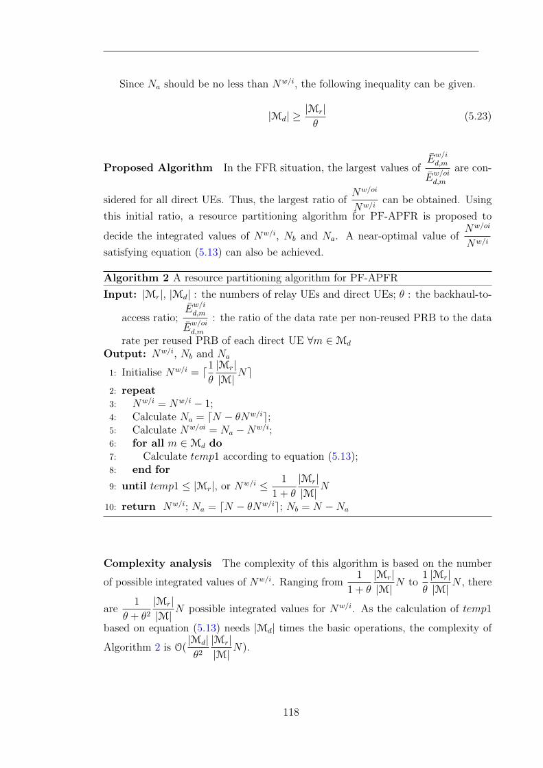
Since Na should be no less than Nw/i, the following inequality can be given.
|Md| ≥|Mr|θ
(5.23)
Proposed Algorithm In the FFR situation, the largest values ofEw/id,m
Ew/oid,m
are con-
sidered for all direct UEs. Thus, the largest ratio ofNw/oi
Nw/ican be obtained. Using
this initial ratio, a resource partitioning algorithm for PF-APFR is proposed to
decide the integrated values of Nw/i, Nb and Na. A near-optimal value ofNw/oi
Nw/i
satisfying equation (5.13) can also be achieved.
Algorithm 2 A resource partitioning algorithm for PF-APFR
Input: |Mr|, |Md| : the numbers of relay UEs and direct UEs; θ : the backhaul-to-
access ratio;Ew/id,m
Ew/oid,m
: the ratio of the data rate per non-reused PRB to the data
rate per reused PRB of each direct UE ∀m ∈Md
Output: Nw/i, Nb and Na
1: Initialise Nw/i = d1θ
|Mr||M|
Ne2: repeat3: Nw/i = Nw/i − 1;4: Calculate Na = dN − θNw/ie;5: Calculate Nw/oi = Na −Nw/i;6: for all m ∈Md do7: Calculate temp1 according to equation (5.13);8: end for
9: until temp1 ≤ |Mr|, or Nw/i ≤ 1
1 + θ
|Mr||M|
N
10: return Nw/i; Na = dN − θNw/ie; Nb = N −Na
Complexity analysis The complexity of this algorithm is based on the number
of possible integrated values of Nw/i. Ranging from1
1 + θ
|Mr||M|
N to1
θ
|Mr||M|
N , there
are1
θ + θ2|Mr||M|
N possible integrated values for Nw/i. As the calculation of temp1
based on equation (5.13) needs |Md| times the basic operations, the complexity of
Algorithm 2 is O(|Md|θ2|Mr||M|
N).
118
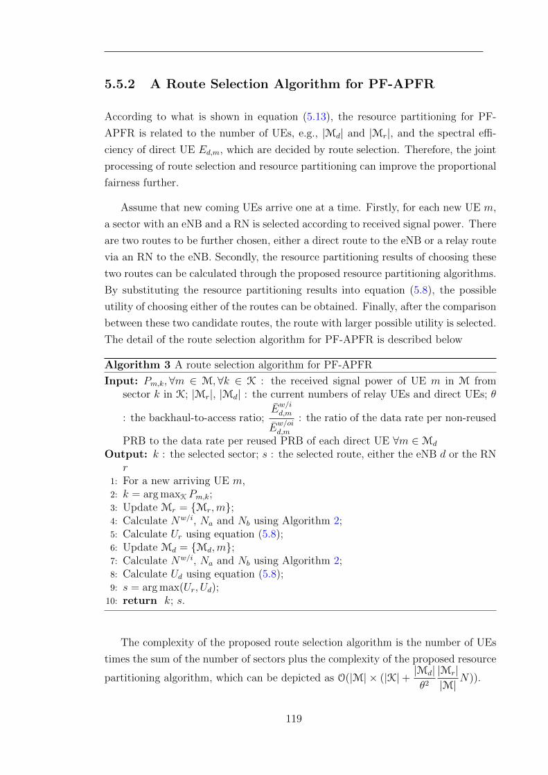
5.5.2 A Route Selection Algorithm for PF-APFR
According to what is shown in equation (5.13), the resource partitioning for PF-
APFR is related to the number of UEs, e.g., |Md| and |Mr|, and the spectral effi-
ciency of direct UE Ed,m, which are decided by route selection. Therefore, the joint
processing of route selection and resource partitioning can improve the proportional
fairness further.
Assume that new coming UEs arrive one at a time. Firstly, for each new UE m,
a sector with an eNB and a RN is selected according to received signal power. There
are two routes to be further chosen, either a direct route to the eNB or a relay route
via an RN to the eNB. Secondly, the resource partitioning results of choosing these
two routes can be calculated through the proposed resource partitioning algorithms.
By substituting the resource partitioning results into equation (5.8), the possible
utility of choosing either of the routes can be obtained. Finally, after the comparison
between these two candidate routes, the route with larger possible utility is selected.
The detail of the route selection algorithm for PF-APFR is described below
Algorithm 3 A route selection algorithm for PF-APFR
Input: Pm,k,∀m ∈ M, ∀k ∈ K : the received signal power of UE m in M fromsector k in K; |Mr|, |Md| : the current numbers of relay UEs and direct UEs; θ
: the backhaul-to-access ratio;Ew/id,m
Ew/oid,m
: the ratio of the data rate per non-reused
PRB to the data rate per reused PRB of each direct UE ∀m ∈Md
Output: k : the selected sector; s : the selected route, either the eNB d or the RNr
1: For a new arriving UE m,2: k = arg maxK Pm,k;3: Update Mr = {Mr,m};4: Calculate Nw/i, Na and Nb using Algorithm 2;5: Calculate Ur using equation (5.8);6: Update Md = {Md,m};7: Calculate Nw/i, Na and Nb using Algorithm 2;8: Calculate Ud using equation (5.8);9: s = arg max(Ur, Ud);
10: return k; s.
The complexity of the proposed route selection algorithm is the number of UEs
times the sum of the number of sectors plus the complexity of the proposed resource
partitioning algorithm, which can be depicted as O(|M| × (|K|+ |Md|θ2|Mr||M|
N)).
119
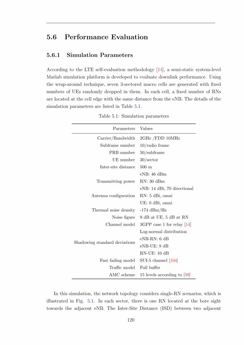
5.6 Performance Evaluation
5.6.1 Simulation Parameters
According to the LTE self-evaluation methodology [14], a semi-static system-level
Matlab simulation platform is developed to evaluate downlink performance. Using
the wrap-around technique, seven 3-sectored macro cells are generated with fixed
numbers of UEs randomly dropped in them. In each cell, a fixed number of RNs
are located at the cell edge with the same distance from the eNB. The details of the
simulation parameters are listed in Table 5.1.
Table 5.1: Simulation parameters
Parameters Values
Carrier/Bandwidth 2GHz /FDD 10MHz
Subframe number 10/radio frame
PRB number 50/subframe
UE number 30/sector
Inter-site distance 500 m
Transmitting power
eNB: 46 dBm
RN: 30 dBm
Antenna configuration
eNB: 14 dBi, 70 directional
RN: 5 dBi, omni
UE: 0 dBi, omni
Thermal noise density -174 dBm/Hz
Noise figure 9 dB at UE, 5 dB at RN
Channel model 3GPP case 1 for relay [14]
Shadowing standard deviations
Log-normal distribution
eNB-RN: 6 dB
eNB-UE: 8 dB
RN-UE: 10 dB
Fast fading model SUI-5 channel [104]
Traffic model Full buffer
AMC scheme 15 levels according to [59]
In this simulation, the network topology considers single-RN scenarios, which is
illustrated in Fig. 5.1. In each sector, there is one RN located at the bore sight
towards the adjacent eNB. The Inter-Site Distance (ISD) between two adjacent
120
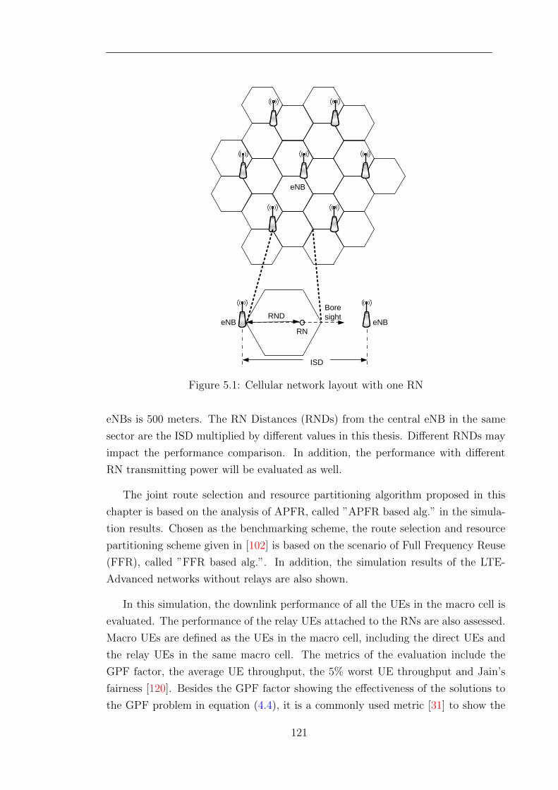
eNB
Bore sightRND
RNeNB eNB
ISD
Figure 5.1: Cellular network layout with one RN
eNBs is 500 meters. The RN Distances (RNDs) from the central eNB in the same
sector are the ISD multiplied by different values in this thesis. Different RNDs may
impact the performance comparison. In addition, the performance with different
RN transmitting power will be evaluated as well.
The joint route selection and resource partitioning algorithm proposed in this
chapter is based on the analysis of APFR, called ”APFR based alg.” in the simula-
tion results. Chosen as the benchmarking scheme, the route selection and resource
partitioning scheme given in [102] is based on the scenario of Full Frequency Reuse
(FFR), called ”FFR based alg.”. In addition, the simulation results of the LTE-
Advanced networks without relays are also shown.
In this simulation, the downlink performance of all the UEs in the macro cell is
evaluated. The performance of the relay UEs attached to the RNs are also assessed.
Macro UEs are defined as the UEs in the macro cell, including the direct UEs and
the relay UEs in the same macro cell. The metrics of the evaluation include the
GPF factor, the average UE throughput, the 5% worst UE throughput and Jain’s
fairness [120]. Besides the GPF factor showing the effectiveness of the solutions to
the GPF problem in equation (4.4), it is a commonly used metric [31] to show the
121
trade-off between average throughput and fairness, which is expressed as:
GPF factor =1
|M|∑m∈M
logRm (5.24)
Jain’s fairness index proposed in [120] is also a quantitative measure of fairness
for resource allocation, which can identify the proportion of under-allocation. Jain’s
fairness of n users with xi throughput is described as:
J(x1, x2, . . . , xn) =(∑n
i=1 xi)2
n ·∑n
i=1 x2i
(5.25)
The 5% worst UE throughput is the largest throughput of the 5% UEs with the
worst throughputs, as defined in 3GPP standard [14]. This metric is also used to
indicate the cell-edge performance.
5.6.2 Simulation Results
The performance using the proposed Joint Route Selection and Resource Partition-
ing (JRSRP) algorithm based on APFR and the benchmarking JRSRP algorithm
based on FFR is evaluated when different values are given to the transmitting power
of each RN. The RN transmitting power of 30 dBm, 33 dBm, 36 dBm and 39 dBm
are used in the simulations.
Fig.5.2 shows the GPF factors using different JRSRP algorithms with different
RN transmitting powers. With two-hop relaying, the GPF factors using both the
proposed APFR based JRSRP algorithm and the FFR based algorithm are larger
than those in the LTE-Advanced networks without relays. With the increase of
transmitting power of RNs, better downlink performance of access links can be
achieved, but more severe interference will be generated to the direct links. Because
it is better able to deal with this situation, the APFR based algorithm improves the
GPF factors for different RN transmitting powers, compared with the FFR based
algorithm. It can be observed that the GPF factors using the FFR based JRSRP
algorithm are increasing gently, especially when the RN transmitting power grows
from 36 dBm to 39 dBm. However, the increment of GPF factor using the APFR
based algorithm is more significant between these two RN transmitting powers.
Therefore, the APFR based algorithm may support a larger transmitting power of
RNs in the LTE-Advanced networks in order to provide better proportional fairness.
122
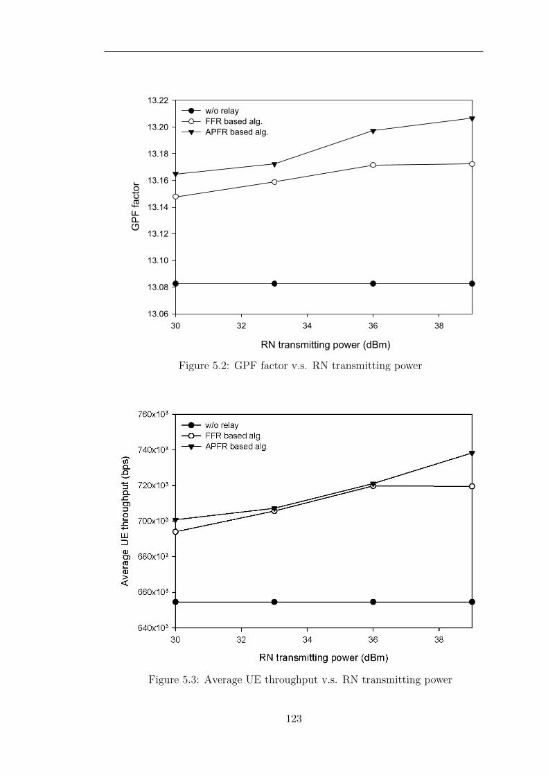
RN transmitting power (dBm)
30 32 34 36 38
GP
F fa
ctor
13.06
13.08
13.10
13.12
13.14
13.16
13.18
13.20
13.22w/o relayFFR based alg.APFR based alg.
Figure 5.2: GPF factor v.s. RN transmitting power
Figure 5.3: Average UE throughput v.s. RN transmitting power
123
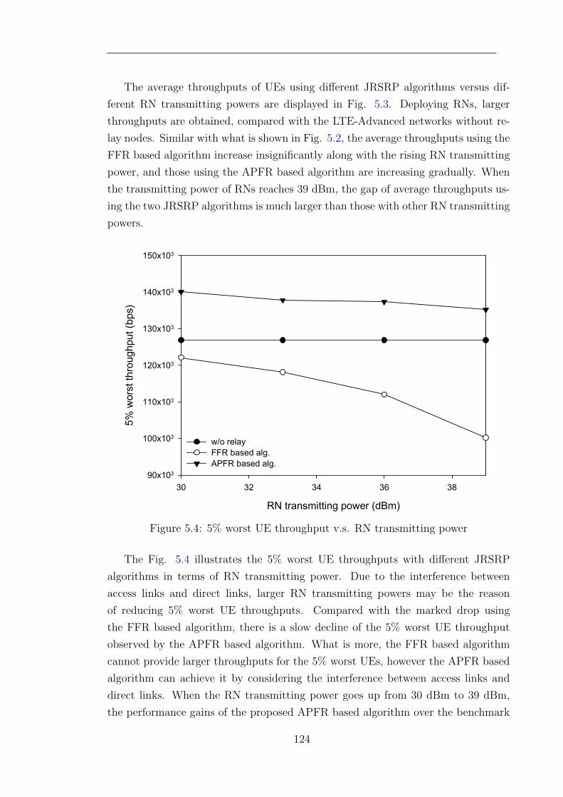
The average throughputs of UEs using different JRSRP algorithms versus dif-
ferent RN transmitting powers are displayed in Fig. 5.3. Deploying RNs, larger
throughputs are obtained, compared with the LTE-Advanced networks without re-
lay nodes. Similar with what is shown in Fig. 5.2, the average throughputs using the
FFR based algorithm increase insignificantly along with the rising RN transmitting
power, and those using the APFR based algorithm are increasing gradually. When
the transmitting power of RNs reaches 39 dBm, the gap of average throughputs us-
ing the two JRSRP algorithms is much larger than those with other RN transmitting
powers.
RN transmitting power (dBm)
30 32 34 36 38
5% w
orst
thr
ough
put (
bps)
90x103
100x103
110x103
120x103
130x103
140x103
150x103
w/o relayFFR based alg.APFR based alg.
Figure 5.4: 5% worst UE throughput v.s. RN transmitting power
The Fig. 5.4 illustrates the 5% worst UE throughputs with different JRSRP
algorithms in terms of RN transmitting power. Due to the interference between
access links and direct links, larger RN transmitting powers may be the reason
of reducing 5% worst UE throughputs. Compared with the marked drop using
the FFR based algorithm, there is a slow decline of the 5% worst UE throughput
observed by the APFR based algorithm. What is more, the FFR based algorithm
cannot provide larger throughputs for the 5% worst UEs, however the APFR based
algorithm can achieve it by considering the interference between access links and
direct links. When the RN transmitting power goes up from 30 dBm to 39 dBm,
the performance gains of the proposed APFR based algorithm over the benchmark
124
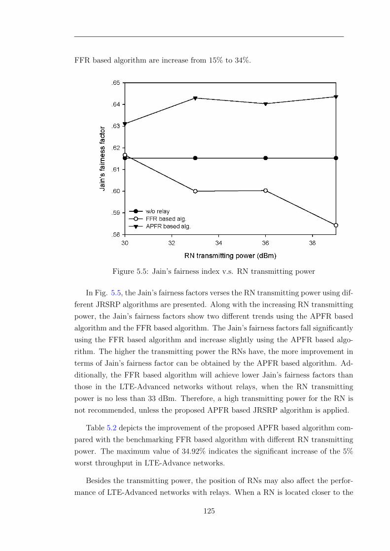
FFR based algorithm are increase from 15% to 34%.
Figure 5.5: Jain’s fairness index v.s. RN transmitting power
In Fig. 5.5, the Jain’s fairness factors verses the RN transmitting power using dif-
ferent JRSRP algorithms are presented. Along with the increasing RN transmitting
power, the Jain’s fairness factors show two different trends using the APFR based
algorithm and the FFR based algorithm. The Jain’s fairness factors fall significantly
using the FFR based algorithm and increase slightly using the APFR based algo-
rithm. The higher the transmitting power the RNs have, the more improvement in
terms of Jain’s fairness factor can be obtained by the APFR based algorithm. Ad-
ditionally, the FFR based algorithm will achieve lower Jain’s fairness factors than
those in the LTE-Advanced networks without relays, when the RN transmitting
power is no less than 33 dBm. Therefore, a high transmitting power for the RN is
not recommended, unless the proposed APFR based JRSRP algorithm is applied.
Table 5.2 depicts the improvement of the proposed APFR based algorithm com-
pared with the benchmarking FFR based algorithm with different RN transmitting
power. The maximum value of 34.92% indicates the significant increase of the 5%
worst throughput in LTE-Advance networks.
Besides the transmitting power, the position of RNs may also affect the perfor-
mance of LTE-Advanced networks with relays. When a RN is located closer to the
125
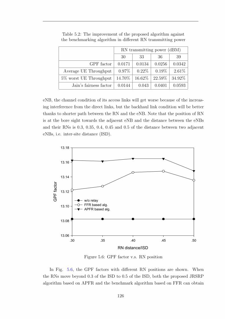
Table 5.2: The improvement of the proposed algorithm againstthe benchmarking algorithm in different RN transmitting power
RN transmitting power (dBM)
30 33 36 39
GPF factor 0.0171 0.0134 0.0256 0.0342
Average UE Throughput 0.97% 0.22% 0.19% 2.61%
5% worst UE Throughput 14.70% 16.62% 22.59% 34.92%
Jain’s fairness factor 0.0144 0.043 0.0401 0.0593
eNB, the channel condition of its access links will get worse because of the increas-
ing interference from the direct links, but the backhaul link condition will be better
thanks to shorter path between the RN and the eNB. Note that the position of RN
is at the bore sight towards the adjacent eNB and the distance between the eNBs
and their RNs is 0.3, 0.35, 0.4, 0.45 and 0.5 of the distance between two adjacent
eNBs, i.e. inter-site distance (ISD).
RN distance/ISD
.30 .35 .40 .45 .50
GP
F fa
ctor
13.06
13.08
13.10
13.12
13.14
13.16
13.18
w/o relayFFR based alg.APFR based alg.
Figure 5.6: GPF factor v.s. RN position
In Fig. 5.6, the GPF factors with different RN positions are shown. When
the RNs move beyond 0.3 of the ISD to 0.5 of the ISD, both the proposed JRSRP
algorithm based on APFR and the benchmark algorithm based on FFR can obtain
126
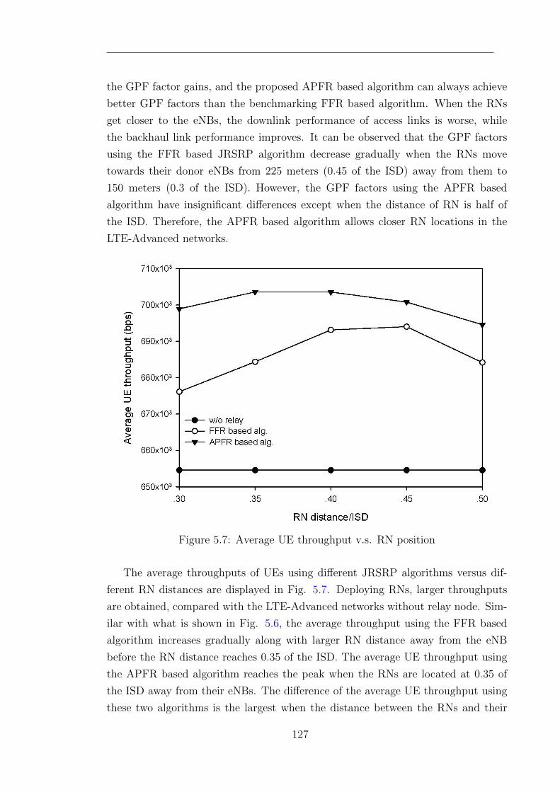
the GPF factor gains, and the proposed APFR based algorithm can always achieve
better GPF factors than the benchmarking FFR based algorithm. When the RNs
get closer to the eNBs, the downlink performance of access links is worse, while
the backhaul link performance improves. It can be observed that the GPF factors
using the FFR based JRSRP algorithm decrease gradually when the RNs move
towards their donor eNBs from 225 meters (0.45 of the ISD) away from them to
150 meters (0.3 of the ISD). However, the GPF factors using the APFR based
algorithm have insignificant differences except when the distance of RN is half of
the ISD. Therefore, the APFR based algorithm allows closer RN locations in the
LTE-Advanced networks.
Figure 5.7: Average UE throughput v.s. RN position
The average throughputs of UEs using different JRSRP algorithms versus dif-
ferent RN distances are displayed in Fig. 5.7. Deploying RNs, larger throughputs
are obtained, compared with the LTE-Advanced networks without relay node. Sim-
ilar with what is shown in Fig. 5.6, the average throughput using the FFR based
algorithm increases gradually along with larger RN distance away from the eNB
before the RN distance reaches 0.35 of the ISD. The average UE throughput using
the APFR based algorithm reaches the peak when the RNs are located at 0.35 of
the ISD away from their eNBs. The difference of the average UE throughput using
these two algorithms is the largest when the distance between the RNs and their
127
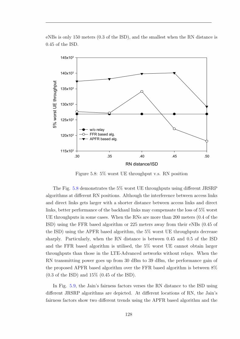
eNBs is only 150 meters (0.3 of the ISD), and the smallest when the RN distance is
0.45 of the ISD.
RN distance/ISD
.30 .35 .40 .45 .50
5% w
orst
UE
thr
ough
put
115x103
120x103
125x103
130x103
135x103
140x103
145x103
w/o relayFFR based alg.APFR based alg.
Figure 5.8: 5% worst UE throughput v.s. RN position
The Fig. 5.8 demonstrates the 5% worst UE throughputs using different JRSRP
algorithms at different RN positions. Although the interference between access links
and direct links gets larger with a shorter distance between access links and direct
links, better performance of the backhaul links may compensate the loss of 5% worst
UE throughputs in some cases. When the RNs are more than 200 meters (0.4 of the
ISD) using the FFR based algorithm or 225 meters away from their eNBs (0.45 of
the ISD) using the APFR based algorithm, the 5% worst UE throughputs decrease
sharply. Particularly, when the RN distance is between 0.45 and 0.5 of the ISD
and the FFR based algorithm is utilised, the 5% worst UE cannot obtain larger
throughputs than those in the LTE-Advanced networks without relays. When the
RN transmitting power goes up from 30 dBm to 39 dBm, the performance gain of
the proposed APFR based algorithm over the FFR based algorithm is between 8%
(0.3 of the ISD) and 15% (0.45 of the ISD).
In Fig. 5.9, the Jain’s fairness factors verses the RN distance to the ISD using
different JRSRP algorithms are depicted. At different locations of RN, the Jain’s
fairness factors show two different trends using the APFR based algorithm and the
128
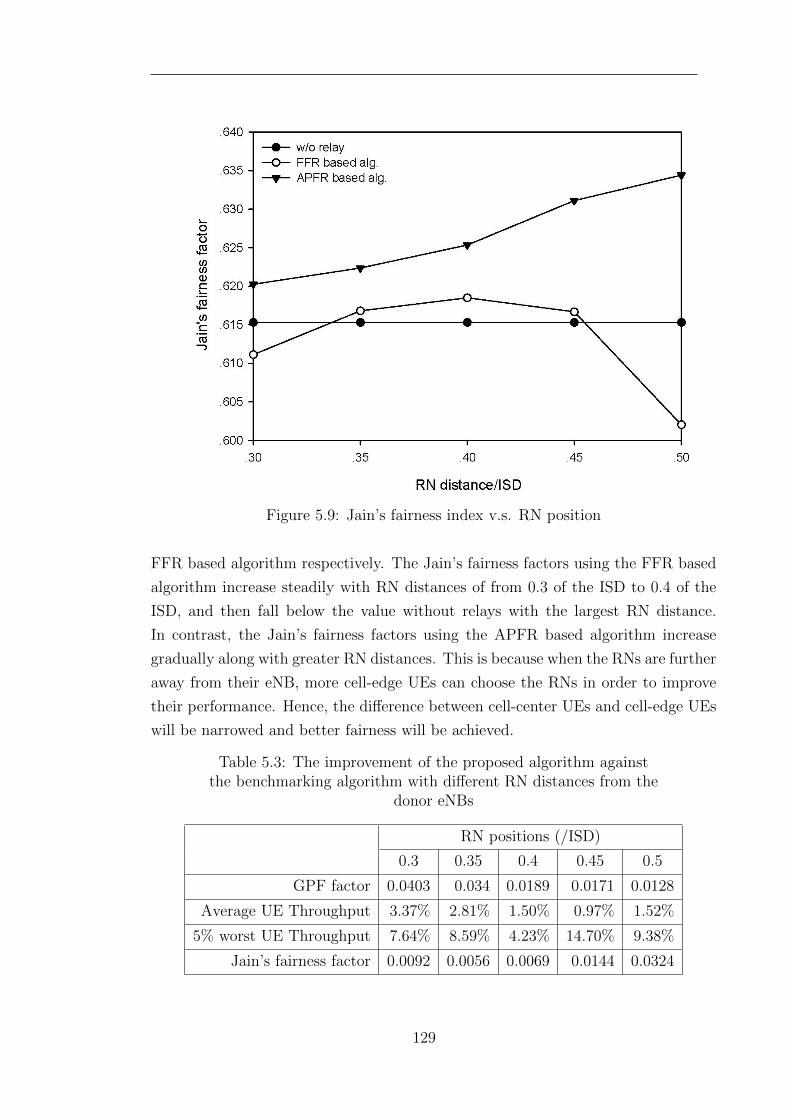
Figure 5.9: Jain’s fairness index v.s. RN position
FFR based algorithm respectively. The Jain’s fairness factors using the FFR based
algorithm increase steadily with RN distances of from 0.3 of the ISD to 0.4 of the
ISD, and then fall below the value without relays with the largest RN distance.
In contrast, the Jain’s fairness factors using the APFR based algorithm increase
gradually along with greater RN distances. This is because when the RNs are further
away from their eNB, more cell-edge UEs can choose the RNs in order to improve
their performance. Hence, the difference between cell-center UEs and cell-edge UEs
will be narrowed and better fairness will be achieved.
Table 5.3: The improvement of the proposed algorithm againstthe benchmarking algorithm with different RN distances from the
donor eNBs
RN positions (/ISD)
0.3 0.35 0.4 0.45 0.5
GPF factor 0.0403 0.034 0.0189 0.0171 0.0128
Average UE Throughput 3.37% 2.81% 1.50% 0.97% 1.52%
5% worst UE Throughput 7.64% 8.59% 4.23% 14.70% 9.38%
Jain’s fairness factor 0.0092 0.0056 0.0069 0.0144 0.0324
129
Table 5.3 describes the performance gains of the proposed APFR based algorithm
compared with the benchmarking FFR based algorithm with different RN distances
from the donor eNBs.
5.7 Conclusion
This chapter presents a preliminary study on adaptive partial frequency reusing
(APFR) in LTE-Advanced networks with RNs. Proportional fairness is consid-
ered as the performance metric in order to make an effective compromise between
throughput and fairness. This study starts with the scenario of one RN in each cell.
The generalised proportional fairness (GPF) problem is utilised to formulate the
APFR problem for maximising proportional fairness. Thereafter, the GPF prob-
lem for APFR is decomposed into two sub-problems, proportional fair based route
selection and resource partitioning. This chapter proposes the APFR based joint
route selection and resource partitioning (JRSRP) algorithm as a near-optimal solu-
tion. Through an experimental performance evaluation, it can be confirmed that the
proposed APFR based JRSRP algorithm achieves better proportional fairness than
the FFR based JRSRP algorithm. Both throughput and fairness are improved. In
addition, because of the better APFR solutions, the increase of interference caused
by higher transmitting power and less RN distance can be alleviated. The proposed
algorithm will increase the computation complexity of the eNBs and the RNs, how-
ever it will not require more signalling channels between the RNs and the donor
eNBs.
130
Chapter 6
Conclusions and Future Work
6.1 Introduction
In this chapter, the research work described in this thesis is summarised. The
significance of my contributions to distributed RRM techniques in relay enhanced
LTE-Advanced networks is highlighted. Three RRM techniques proposed in this
thesis include service-aware adaptive bidirectional optimisation route selection, dis-
tributed two-hop proportional fair resource scheduling and adaptive two-hop partial
frequency reusing. Some potential topics for future work are also given in this chap-
ter.
6.2 Contributions
Overview of Solutions
The purpose of my research is to rise to the challenges of RRM in the LTE-Advanced
networks with in-band half-duplex RNs associated with the introduction of two-hop
in-band transmission and low-power RNs. Since the RRM techniques in the single-
hop networks may lead to imbalances in two-hop networks, the aim of my research is
to achieve a rebalance by designing new techniques in addition to RRM procedures.
In order to avoid the imbalance between uplink optimisation and downlink optimi-
sation as the result of a large difference between transmitting power of an eNB and
an RN, a service-aware adaptive bidirectional optimisation (ABO) route selection
131
algorithm was proposed. Since fixed resource partitioning is utilised in the ABO
algorithm, load balancing is also considered. Based on different adaptive resource
partitioning schemes, distributed two-hop proportional fair resource scheduling algo-
rithms were proposed. Because the resource scheduling of access links and backhaul
links should be re-balanced in order to satisfy the matching of data rates in the
two hops and the resource numbers in each of the two hops. In order to rebalance
the benefits of frequency reusing with the performance loss caused by co-channel
interference at the reusing frequency, adaptive two-hop partial frequency reusing is
studied in this thesis. A proportional fair joint route selection and resource parti-
tioning algorithm is proposed to obtain a near-optimal solution.
Service-Aware Adaptive Bidirectional Optimisation Route Selection
A service-aware adaptive bidirectional optimisation (ABO) route selection strategy
with load balancing is proposed in order to rebalance uplink optimisation and down-
link optimisation. The main target of this strategy is to maximise the bidirectional
throughput which is the sum of the uplink throughput and the downlink through-
put. A traffic model is assumed in the formulation of maximising the bidirectional
throughput using route selection, in which there are different types of services with
different uplink and downlink requirements. Load balancing is considered by its
integration in the ABO strategy in order to improve system performance in heavy-
loaded scenarios.
Through a static system-level simulation, the ABO strategy is compared with
two benchmark strategies: the Received Signal Power (RSP) based strategy and the
Range Expansion (RE) based strategy, with different frame configurations. Both a
Round-Robin resource scheduling algorithm and a proportional fair resource schedul-
ing algorithm are deployed. Both 20 MHz and 10 MHz frequency bandwidths are
considered. Simulation results show that the ABO strategy is superior to the other
two strategies in two points: 1) achieving higher average bidirectional throughput
for different frame configurations because of the inherent load balancing feature, and
2) providing better performance for uplink-biased UEs, for example up to 14% gain
is achieved in the mean user uplink throughput. Besides, the performance gain of
the proposed ABO strategy is larger when 10 MHz frequency bandwidth is applied
because the integrated load balancing mechanism can avoid early overloading.
132
Distributed Two-hop Proportional Fair Resource Allocation
The distributed two-hop proportional fair (DTHPF) resource allocation scheme in-
cludes the proposed proportional fair resource scheduling algorithms and adaptive
resource partitioning algorithms. The individual resource scheduling processes in
the access links and the backhaul links are rebalanced by considering two-hop data
rate matching and the resource number constraints between access links and back-
haul links. The purpose of the proposed DTHPF resource allocation algorithms is to
maximise two-hop end-to-end proportional fairness in the LTE-Advanced networks
with RNs. Two different two-hop transmission protocols are considered, which are
orthogonal two-hop (OTH) transmission protocol and simultaneous two-hop (STH)
transmission protocol. The generalised proportional fairness (GPF) problem using
two protocols is formulated and decomposed into two related sub-problems, i.e., a
resource partitioning problem and a resource scheduling problem. By adopting the
existing resource partitioning solutions, the resource scheduling problem constrained
by the two-hop resource partitioning is given and solved using the Lagrangian mul-
tiplier method.
Semi-static system level simulation results show that the proposed DTHPF re-
source allocation scheme achieves a better compromise between throughput and
fairness. The orthogonal reuse (OR) pattern in the OTH protocol and the full reuse
(FR), 2/3 partial reuse (PR) and 1/3 PR patterns in the STH protocol are con-
sidered as the scenarios for the performance evaluations. Through simulations, the
following facts can be observed:
1. The proposed DTHPF resource allocation scheme has better GPF factors and
better 5% worst UE throughputs, with different RN numbers for all the reuse
patterns.
2. The performance of macro UEs in the OR pattern is better than that in the
FR pattern, because extra intra-cell interference is generated by reusing the
same PRB in direct links and access links in the FR pattern. However, the
performance of relay UEs in the FR pattern is better than that in the OR
pattern.
3. With less intra-cell interference and less resources for the access links, the
performance in the 1/3 PR pattern is better than that in the FR pattern using
the proposed scheme and the benchmark scheme. Meanwhile, the performance
gains achieved by the proposed scheme compared with the benchmark scheme
133
is smaller in the 1/3 PR pattern than in the FR and 2/3 PR patterns.
4. As a compromise between the FR pattern and the 1/3 PR pattern, the 2/3
PR pattern can achieve better performance, and significant performance gain
can be obtained using the proposed scheme.
Adaptive Two-Hop Partial Frequency Reusing
This thesis also proposes a proportional fair joint route selection and resource parti-
tioning algorithm for adaptive partial frequency reusing (APFR) in LTE-Advanced
networks with RNs. Proportional fairness is considered as the performance metric
in order to make an effective compromise between throughput and fairness. This
study starts with the scenario of one RN in each cell. For maximising proportional
fairness, the Generalised proportional fairness (GPF) problem is utilised to formu-
late the APFR problem. Thereafter, the GPF problem for APFR is decomposed
into two sub-problems, which are a route selection problem and a resource parti-
tioning problem. A proportional fair joint route selection and resource partitioning
(JRSRP) algorithm is proposed as a improved solution for the APFR problem.
In the system-level simulation, the performance using both the proposed APFR
based JRSRP algorithm and the benchmarking FFR based JRSRP algorithm is
evaluated with different RN transmitting powers and different RN positions. The
simulation results show that the proposed APFR based algorithm can achieve larger
GPF factors, throughputs and Jain’s fairness factors. Especially, the 5% worst UE
throughput is improved by at least 8% to up to 34%, and hence cell-edge UEs
are dramatically better off. When the RN transmitting power is higher and the
RNs are closer to the eNB, the increase in interference is alleviated by the proposed
APFR based algorithm, since the balance between frequency reusing and co-channel
interference is better solved.
6.3 Future Works
Adaptive Bidirectional Optimisation Route Selection
When service types and load balancing are considered in the ABO route selection
strategy, fair-share resource scheduling algorithms, such as Round-Robin scheduling
134
and proportional fair scheduling, are considered. For some service types, a through-
put threshold is required. Thus, throughput aware fair-share scheduling algorithms,
such as max-min scheduling, should be considered. The ABO strategy should be
extended to include the max-min scheduling algorithm or hybrid scheduling algo-
rithms.
A important issue of route selection in relay enhanced LTE-Advanced networks
is energy efficiency. The power consumption of eNB, RN and UE can be considered
together with the system performance in order to maximise the performance metrics
with regard to power consumption. Since eNBs, RNs and UEs have different sources
of power supply, e.g. UEs are supported by batteries and eNBs are supplied by
industrial power, a new energy consumption metric is needed.
Distributed Two-Hop Proportional Fair Resource allocation
The DTHPF resource allocation scheme only considers the downlink, which may be
extended to the uplink. In the LTE uplink, SC-FDMA is deployed. Therefore, the
resource scheduling in the LTE uplink should comply with some different rules. For
example, the resources allocated to a UE should be consecutive and one UE should
be scheduled just for once.
The resource constraints of access links and backhaul links determine the resource
scheduling algorithms. Two special situations are considered in this thesis. In the
none frequency reuse case, the sum of the access resource number and the backhaul
resource number is proportional to the UE number; in the fixed frequency reuse case,
either the access resource number or the backhaul resource number is the constraint.
However, a more generalised situation can be considered for the generalisation of
DTHPF resource allocation.
Adaptive Two-Hop Partial Frequency Reusing
The research on adaptive partial frequency reusing (APFR) in this thesis is a pre-
liminary study. Only one RN in a sector is considered. Multiple RNs per cell can
be considered to improve performance further.
The joint route selection and resource partitioning algorithm for APFR proposed
in this thesis has higher complexity than the conventional received signal power
based route selection algorithm and the full frequency reusing (FFR) based resource
135
partitioning algorithm. Thus, a low-complexity algorithm is needed in order to
provide a balance between the effectiveness and the complexity of the proposed
algorithm.
136
References
[1] H. Kaaranen, A. Ahtiainen, L. Laitinen, S. Naghian, and V. Niemi,
UMTS Networks: Architecture, Mobility and Services. Wiley, Apr.
2005. [Online]. Available: http://www.amazon.com/exec/obidos/redirect?
tag=citeulike07-20&path=ASIN/0470011033
[2] T. Halonen, J. Romero, and J. Melero, GSM, GPRS and EDGE Performance:
Evolution Towards 3G/UMTS. John Wiley & Sons, 2003.
[3] A. Furuskar, S. Mazur, F. Muller, and H. Olofsson, “EDGE: enhanced data
rates for GSM and TDMA/136 evolution,” Personal Communications, IEEE,
vol. 6, no. 3, pp. 56–66, 1999.
[4] M. Mouly and M.-B. Pautet, The GSM System for Mobile Communications.
Telecom Publishing, 1992.
[5] E. Dahlman, B. Gudmundson, M. Nilsson, and A. Skold, “UMTS/IMT-2000
based on wideband CDMA,” Communications Magazine, IEEE, vol. 36, no. 9,
pp. 70–80, 1998.
[6] C. Smith, 3G Wireless Networks. McGraw-Hill Professional, 2001.
[7] H.-H. Chen, C.-X. Fan, and W. Lu, “China’s perspectives on 3G mobile com-
muunications and beyond: TD-SCDMA technology,” Wireless Communica-
tions, IEEE, vol. 9, no. 2, pp. 48–59, 2002.
[8] J. Zhang, J. Huai, R. Xiao, and B. Li, “Resource management in the next-
generation DS-CDMA cellular networks,” Wireless Communications, IEEE,
vol. 11, no. 4, pp. 52–58, 2004.
[9] D. Astely, E. Dahlman, A. Furuskar, Y. Jading, M. Lindstrom, and S. Parkvall,
“LTE: the evolution of mobile broadband,” Communications Magazine, IEEE,
vol. 47, no. 4, pp. 44–51, 2009.
137
REFERENCES
[10] K. Pedersen, T. Kolding, F. Frederiksen, I. Kovacs, D. Laselva, and P. Mo-
gensen, “An overview of downlink radio resource management for UTRAN
long-term evolution,” Communications Magazine, IEEE, vol. 47, no. 7, pp.
86–93, 2009.
[11] R. Kwan, C. Leung, and J. Zhang, “Proportional Fair Multiuser Scheduling
in LTE,” Signal Processing Letters, IEEE, vol. 16, no. 6, pp. 461–464, 2009.
[12] C. Wijting, K. Doppler, K. Kalliojarvi, T. Svensson, M. Sternad, G. Auer,
N. Johansson, J. Nystrom, M. Olsson, A. Osseiran, M. Dottling, J. Luo,
T. Lestable, and S. Pfletschinger, “Key technologies for IMT-advanced mobile
communication systems,” Wireless Communications, IEEE, vol. 16, no. 3, pp.
76–85, 2009.
[13] I. F. Akyildiz, D. M. Gutierrez-Estevez, and E. C. Reyes, “The
Evolution to 4G Cellular Systems: LTE-Advanced,” Phys. Commun.,
vol. 3, no. 4, pp. 217–244, Dec. 2010. [Online]. Available: http:
//dx.doi.org/10.1016/j.phycom.2010.08.001
[14] 3GPP, Evolved Universal Terrestrial Radio Access (E-UTRA); Further
advancements for E-UTRA physical layer aspects, 3GPP TR 36.814. [Online].
Available: http://www.3gpp.org/ftp/Specs/html-info/36814.htm
[15] S. Parkvall, E. Dahlman, A. Furuskar, Y. Jading, M. Olsson, S. Wanstedt,
and K. Zangi, “LTE-Advanced - Evolving LTE towards IMT-Advanced,” in
Vehicular Technology Conference, 2008. VTC 2008-Fall. IEEE 68th, 2008, pp.
1–5.
[16] 3GPP, Requirements for further advancements for E-UTRA (LTE-Advanced),
3rd Generation Partnership Project (3GPP) TR 36.913, Jun. 2008. [Online].
Available: http://www.3gpp.org/ftp/Specs/html-info/36913.htm
[17] F. P. Kelly, “Charging and rate control for elastic traffic,” European Transac-
tions on Telecommunications, vol. volume 8, pp. 33–37, 1997.
[18] 3GPP, Requirements for Evolved UTRA (E-UTRA) and Evolved UTRAN (E-
UTRAN), 3rd Generation Partnership Project (3GPP) TR 25.913, Mar. 2006.
[Online]. Available: http://www.3gpp.org/ftp/Specs/html-info/25913.htm
[19] R. v. Nee and R. Prasad, OFDM for Wireless Multimedia Communications,
1st ed. Norwood, MA, USA: Artech House, Inc., 2000.
138
REFERENCES
[20] R. Prasad, OFDM for Wireless Communications Systems. Norwood, MA,
USA: Artech House, Inc., 2004.
[21] H. Myung, J. Lim, and D. Goodman, “Single carrier FDMA for uplink wireless
transmission,” Vehicular Technology Magazine, IEEE, vol. 1, no. 3, pp. 30–38,
2006.
[22] 3GPP, Evolved Universal Terrestrial Radio Access (E-UTRA) physical
channels and modulation (Release 8), 3GPP TS 36.211. [Online]. Available:
http://www.3gpp.org/ftp/Specs/html-info/36221.htm
[23] 3GPP, Evolved Universal Terrestrial Radio Access (E-UTRA) and Evolved
Universal Terrestrial Radio Access (E-UTRAN); Overall description; Stage 2,
3rd Generation Partnership Project (3GPP) TS 36.300, Sep. 2008. [Online].
Available: http://www.3gpp.org/ftp/Specs/html-info/36300.htm
[24] 3GPP, Feasibility study for evolved Universal Terrestrial Radio Access
(UTRA) and Universal Terrestrial Radio Access Network (UTRAN), 3rd
Generation Partnership Project (3GPP) TR 25.912, Aug. 2007. [Online].
Available: http://www.3gpp.org/ftp/Specs/html-info/25912.htm
[25] 3GPP, Evolved Universal Terrestrial Radio Access (E-UTRA); Radio
Resource Control (RRC); Protocol specification, 3rd Generation Partnership
Project (3GPP) TS 36.331, Sep. 2008. [Online]. Available: http:
//www.3gpp.org/ftp/Specs/html-info/36331.htm
[26] 3GPP, Evolved Universal Terrestrial Radio Access (E-UTRA); Packet Data
Convergence Protocol (PDCP) specification, 3rd Generation Partnership
Project (3GPP) TS 36.323, Sep. 2008. [Online]. Available: http:
//www.3gpp.org/ftp/Specs/html-info/36323.htm
[27] 3GPP, Evolved Universal Terrestrial Radio Access (E-UTRA); Radio
Link Control (RLC) protocol specification, 3rd Generation Partnership
Project (3GPP) TS 36.322, Sep. 2008. [Online]. Available: http:
//www.3gpp.org/ftp/Specs/html-info/36322.htm
[28] 3GPP, Evolved Universal Terrestrial Radio Access (E-UTRA); Medium
Access Control (MAC) protocol specification, 3rd Generation Partnership
Project (3GPP) TS 36.321, Sep. 2008. [Online]. Available: http:
//www.3gpp.org/ftp/Specs/html-info/36321.htm
139
REFERENCES
[29] D. H. Holma and D. A. Toskala, LTE for UMTS - OFDMA and SC-FDMA
Based Radio Access. Wiley Publishing, 2009.
[30] M. Katevenis, S. Sidiropoulos, and C. Courcoubetis, “Weighted round-robin
cell multiplexing in a general-purpose ATM switch chip,” Selected Areas in
Communications, IEEE Journal on, vol. 9, no. 8, pp. 1265–1279, Oct 1991.
[31] S. Borst, “User-level performance of channel-aware scheduling algorithms in
wireless data networks,” Networking, IEEE/ACM Transactions on, vol. 13,
no. 3, pp. 636–647, 2005.
[32] 3GPP, Evolved Universal Terrestrial Radio Access (E-UTRA); Physical layer
procedures, 3rd Generation Partnership Project (3GPP) TS 36.213, Sep. 2008.
[Online]. Available: http://www.3gpp.org/ftp/Specs/html-info/36213.htm
[33] G. Boudreau, J. Panicker, N. Guo, R. Chang, N. Wang, and S. Vrzic, “In-
terference coordination and cancellation for 4G networks,” Communications
Magazine, IEEE, vol. 47, no. 4, pp. 74–81, April 2009.
[34] “R1-082397, Discussion on the various types of Relays,” Panasonic, Tech.
Rep., July 2008.
[35] F. Jiang and B. Wang, “A Load Balancing Relay Selection Algorithm for Re-
lay Based Cellular Networks,” in Wireless Communications, Networking and
Mobile Computing (WiCOM), 2011 7th International Conference on, 2011,
pp. 1–5.
[36] Y. Hu and L. Qiu, “A Novel Multiple Relay Selection Strategy for LTE-
Advanced Relay Systems,” in Vehicular Technology Conference (VTC Spring),
2011 IEEE 73rd, 2011, pp. 1–5.
[37] I. Ben Chaabane, S. Hamouda, and S. Tabbane, “A novel relay selection
scheme for LTE-advanced system under delay and load constraints,” in Wire-
less Communications and Networking Conference Workshops (WCNCW),
2012 IEEE, 2012, pp. 263–267.
[38] F. Vitiello, S. Redana, and J. Hamalainen, “Admission control for LTE-
Advanced relay systems,” in European Wireless, 2012. EW. 18th European
Wireless Conference, 2012, pp. 1–8.
[39] A. A. Rasheed and S. Wager, “Cell range extension in LTE in-band relays:
Analysis of radio link, subframe allocation and protocol perfornance of FTP
140
REFERENCES
traffic model,” in European Wireless, 2012. EW. 18th European Wireless Con-
ference, 2012, pp. 1–6.
[40] A. Saleh, O. Bulakci, S. Redana, B. Raaf, and J. Hamalainen, “Enhancing
LTE-Advanced relay deployments via Biasing in cell selection and handover
decision,” in Personal Indoor and Mobile Radio Communications (PIMRC),
2010 IEEE 21st International Symposium on, 2010, pp. 2277–2281.
[41] “3GPP R1-083813, Range expansion for efficient support of heterogeneous
networks,” Qualcomm Europe, Tech. Rep., October 2008.
[42] “3GPP R1-103264, Performance of eICIC with Control Channel Coverage
Limitation,” NTT DOCOMO, Tech. Rep., May 2010.
[43] I. Guvenc, M.-R. Jeong, I. Demirdogen, B. Kecicioglu, and F. Watanabe,
“Range Expansion and Inter-Cell Interference Coordination (ICIC) for Picocell
Networks,” in Vehicular Technology Conference (VTC Fall), 2011 IEEE, 2011,
pp. 1–6.
[44] C.-S. Chiu and C.-C. Huang, “An Interference Coordination Scheme for Pic-
ocell Range Expansion in Heterogeneous Networks,” in Vehicular Technology
Conference (VTC Spring), 2012 IEEE 75th, 2012, pp. 1–6.
[45] W. Yang, L. Li, G. Wu, H. Wang, and Y. Wang, “Joint Uplink and Downlink
Relay Selection in Cooperative Cellular Networks,” in Vehicular Technology
Conference Fall (VTC 2010-Fall), 2010 IEEE 72nd, 2010, pp. 1–5.
[46] Z. Ma, Y. Zhang, K. Zheng, W. Wang, and M. Wu, “Performance of 3GPP
LTE-Advanced networks with Type I relay nodes,” in Communications and
Networking in China (CHINACOM), 2010 5th International ICST Conference
on, 2010, pp. 1–5.
[47] L. Xiao and L. Cuthbert, “Load Based Relay Selection Algorithm for Fairness
in Relay Based OFDMA Cellular Systems,” in Wireless Communications and
Networking Conference, 2009. WCNC 2009. IEEE, 2009, pp. 1–6.
[48] A. Saleh, S. Redana, B. Raaf, T. Riihonen, J. Hamalainen, and R. Wich-
man, “Performance of Amplify-and-Forward and Decode-and-Forward Relays
in LTE-Advanced,” in Vehicular Technology Conference Fall (VTC 2009-Fall),
2009 IEEE 70th, 2009, pp. 1–5.
141
REFERENCES
[49] H. Hu, H. Yanikomeroglu, D. Falconer, and S. Periyalwar, “Range extension
without capacity penalty in cellular networks with digital fixed relays,” in
Global Telecommunications Conference, 2004. GLOBECOM ’04. IEEE, vol. 5,
2004, pp. 3053–3057 Vol.5.
[50] M. Liang, H. Fan, Y. F. Wang, and D. C. Yang, “Power-Based Routing for
Two-Hop OFDMA Cellular Networks with Fixed Relay Stations,” in Wireless
Communications, Networking and Mobile Computing, 2008. WiCOM ’08. 4th
International Conference on, 2008, pp. 1–4.
[51] V. Sreng, H. Yanikomeroglu, and D. D. Falconer, “Relayer selection strategies
in cellular networks with peer-to-peer relaying,” in Vehicular Technology Con-
ference, 2003. VTC 2003-Fall. 2003 IEEE 58th, vol. 3, 2003, pp. 1949–1953
Vol.3.
[52] Z. Ma, K. Zheng, W. Wang, and Y. Liu, “Route Selection Strategies in Cellular
Networks with Two-Hop Relaying,” in Wireless Communications, Networking
and Mobile Computing, 2009. WiCom ’09. 5th International Conference on,
2009, pp. 1–4.
[53] W.-H. Park and S. Bahk, “Resource management policies for fixed relays in
cellular networks,” Computer Communications, vol. 32, no. 4, pp. 703–711,
3/4 2009.
[54] Z. Ma, W. Xiang, H. Long, and W. Wang, “Proportional fair-based in-cell
routing for relay-enhanced cellular networks,” in Wireless Communications
and Networking Conference (WCNC), 2011 IEEE, 2011, pp. 381–385.
[55] J. Lee, H. Wang, W. Seo, and D. Hong, “QoS-guaranteed transmission mode
selection for efficient resource utilization in multi-hop cellular networks,” Wire-
less Communications, IEEE Transactions on, vol. 7, no. 10, pp. 3697–3701,
2008.
[56] T. Liu and M. Rong, “Utility-based joint routing and spectrum partitioning in
relay LTE-Advanced networks,” in Personal Indoor and Mobile Radio Com-
munications (PIMRC), 2011 IEEE 22nd International Symposium on, 2011,
pp. 1914–1918.
[57] H. Ekstrom, “QoS control in the 3GPP evolved packet system,” Communica-
tions Magazine, IEEE, vol. 47, no. 2, pp. 76–83, 2009.
142
REFERENCES
[58] L. Lei, C. Lin, J. Cai, and X. Shen, “Flow-level performance of opportunis-
tic OFDM-TDMA and OFDMA networks,” Wireless Communications, IEEE
Transactions on, vol. 7, no. 12, pp. 5461–5472, 2008.
[59] J. Ikuno, M. Wrulich, and M. Rupp, “System Level Simulation of LTE Net-
works,” in Vehicular Technology Conference (VTC 2010-Spring), 2010 IEEE
71st, 2010, pp. 1–5.
[60] T. S. Rappaport, Wireless communications: principles and practice, 2nd ed.
Upper Saddle River, N.J: Prentice Hall PTR, 2002.
[61] J. S. Hunter, “The exponentially weighted moving average.” Journal of Quality
Technology, vol. 18, no. 4, pp. 203–210, 1986.
[62] K. Balachandran, S. R. Kadaba, and S. Nanda, “Channel Quality
Estimation and Rate Adaptation for Cellular Mobile Radio,” IEEE J.Sel.
A. Commun., vol. 17, no. 7, pp. 1244–1256, Sep. 2006. [Online]. Available:
http://dx.doi.org/10.1109/49.778183
[63] J.-G. Choi and S. Bahk, “Cell-Throughput Analysis of the Proportional
Fair Scheduler in the Single-Cell Environment,” Vehicular Technology, IEEE
Transactions on, vol. 56, no. 2, pp. 766–778, 2007.
[64] W. Ying, W. Tong, H. Jing, S. Chao, Y. Xinmin, and Z. Ping, “Adaptive
Radio Resource Allocation with Novel Priority Strategy Considering Resource
Fairness in OFDM-Relay System,” in Vehicular Technology Conference, 2007.
VTC-2007 Fall. 2007 IEEE 66th, 2007, pp. 1872–1876.
[65] L. Huang, M. Rong, L. Wang, Y. Xue, and E. Schulz, “Resource Scheduling
for OFDMA/TDD Based Relay Enhanced Cellular Networks,” in Wireless
Communications and Networking Conference, 2007.WCNC 2007. IEEE, 2007,
pp. 1544–1548.
[66] L. Wang, Y. Ji, and F. Liu, “A Novel Centralized Resource Scheduling Scheme
in OFDMA-based Two-Hop Relay-Enhanced Cellular Systems,” in Networking
and Communications, 2008. WIMOB ’08. IEEE International Conference on
Wireless and Mobile Computing,, 2008, pp. 113–118.
[67] M. Salem, A. Adinoyi, H. Yanikomeroglu, D. Falconer, and Y.-D. Kim, “A Fair
Radio Resource Allocation Scheme for Ubiquitous High-Data-Rate Coverage
in OFDMA-Based Cellular Relay Networks,” in Global Telecommunications
Conference, 2009. GLOBECOM 2009. IEEE, 2009, pp. 1–6.
143
REFERENCES
[68] L. Xiao and L. Cuthbert, “A Two-Hop Proportional Fairness Scheduling Al-
gorithm for Relay Based OFDMA Systems,” in Wireless Communications,
Networking and Mobile Computing, 2008. WiCOM ’08. 4th International Con-
ference on, 2008, pp. 1–4.
[69] L. Xiao, T. Zhang, Y. Zhu, and L. Cuthbert, “Two-Hop Subchannel Schedul-
ing and Power Allocation for Fairness in OFDMA Relay Networks,” in Wire-
less and Mobile Communications, 2009. ICWMC ’09. Fifth International Con-
ference on, 2009, pp. 267–271.
[70] W.-G. Ahn and H.-M. Kim, “Proportional fair scheduling in relay enhanced
cellular OFDMA systems,” in Personal, Indoor and Mobile Radio Communi-
cations, 2008. PIMRC 2008. IEEE 19th International Symposium on, 2008,
pp. 1–4.
[71] Y. Hua, Q. Zhang, and Z. Niu, “Resource Allocation in Multi-cell OFDMA-
based Relay Networks.” in INFOCOM, 2010, pp. 2133–2141.
[72] C. Liu, X. Qin, S. Zhang, and W. Zhou, “Proportional-fair downlink resource
allocation in OFDMA-based relay networks,” Communications and Networks,
Journal of, vol. 13, no. 6, pp. 633–638, 2011.
[73] L. You, M. Song, J. Song, Q. Miao, and Y. Zhang, “Adaptive Resource Allo-
cation in OFDMA Relay-Aided Cooperative Cellular Networks,” in Vehicular
Technology Conference, 2008. VTC Spring 2008. IEEE, 2008, pp. 1925–1929.
[74] W.-P. Chang, J.-S. Lin, and K.-T. Feng, “QoS-based resource allocation for
relay-enhanced OFDMA networks.” in WCNC, 2011, pp. 321–326.
[75] Z. Jin and L. Vandendorpe, “Resource Allocation in Multi-Cellular DF Re-
layed OFDMA Systems.” in GLOBECOM, 2011, pp. 1–5.
[76] L. Wang, Y. Ji, and F. Liu, “A Semi-Distributed Resource Allocation Scheme
for OFDMA Relay-Enhanced Downlink Systems,” in GLOBECOM Work-
shops, 2008 IEEE, 2008, pp. 1–6.
[77] L. Jiang, J. Pang, G. Shen, and D. Wang, “A game theoretic channel allocation
scheme for multi-user OFDMA relay system,” in Wireless Communications
and Networking Conference (WCNC), 2011 IEEE, 2011, pp. 298–303.
[78] K. Sundaresan and S. Rangarajan, “Adaptive resource scheduling in wireless
OFDMA relay networks,” in INFOCOM, 2012 Proceedings IEEE, 2012, pp.
1080–1088.
144
REFERENCES
[79] Q. Li, R. Hu, Y. Qian, and G. Wu, “A proportional fair radio resource allo-
cation for heterogeneous cellular networks with relays,” in Global Communi-
cations Conference (GLOBECOM), 2012 IEEE, 2012, pp. 5457–5463.
[80] H. Ju, B. Liang, J. Li, and X. Yang, “Dynamic Joint Resource Optimization
for LTE-Advanced Relay Networks,” Wireless Communications, IEEE Trans-
actions on, vol. 12, no. 11, pp. 5668–5678, 2013.
[81] M. J. Neely, Stochastic Network Optimization with Application to Commu-
nication and Queueing Systems, ser. Synthesis Lectures on Communication
Networks. Morgan & Claypool Publishers, 2010.
[82] M. Kaneko and P. Popovski, “Adaptive Resource Allocation in Cellular
OFDMA System with Multiple Relay Stations.” in VTC Spring, 2007, pp.
3026–3030.
[83] W. Wang, J. Liu, D. Li, and Y. Xu, “Throughput-Based Adaptive Resource-
Allocation Algorithm for OFDMA Cellular System with Relay Stations,”
in Global Telecommunications Conference (GLOBECOM 2011), 2011 IEEE,
2011, pp. 1–5.
[84] S. Yi and M. Lei, “Backhaul resource allocation in LTE-Advanced relaying
systems.” in WCNC, 2012, pp. 1207–1211.
[85] Y.-S. Lu, Y.-B. Lin, and Y. T. Su, “Dynamic Resource Allocation for Relay-
Based OFDMA Systems with Fairness Considerations.” in WCNC, 2010, pp.
1–6.
[86] T. M. d. Moraes, G. Bauch, and E. Seidel, “QoS-aware Scheduling for In-Band
Relays in LTE-Advanced,” in Systems, Communication and Coding (SCC),
Proceedings of 2013 9th International ITG Conference on, 2013, pp. 1–6.
[87] T. M. de Moraes, M. D. Nisar, A. A. Gonzalez, and E. Seidel, “Resource
allocation in relay enhanced LTE-Advanced networks,” EURASIP Journal on
Wireless Communications and Networking, vol. 2012, no. 1, pp. 1–12, 2012.
[88] Z. Zhao, J. Wang, S. Redana, and B. Raaf, “Downlink Resource Allocation for
LTE-Advanced Networks with Type1 Relay Nodes,” in Vehicular Technology
Conference (VTC Fall), 2012 IEEE, 2012, pp. 1–5.
[89] M. Pikhletsky, F. Khafizov, J. Zhang, and H. Zhuang, “Dynamic Radio Re-
source Management for OFDMA-Based Relay Enhanced Cellular Network.”
in GLOBECOM, 2011, pp. 1–5.
145
REFERENCES
[90] O. Bulakci, A. Saleh, Z. Ren, S. Redana, B. Raaf, and J. Hamalainen, “Two-
step resource sharing and uplink power control optimization in LTE-Advanced
relay networks,” in Multi-Carrier Systems Solutions (MC-SS), 2011 8th In-
ternational Workshop on, 2011, pp. 1–6.
[91] A. Bou Saleh, O. Bulakci, Z. Ren, S. Redana, B. Raaf, and J. Haemaelaeinen,
“Resource Sharing in Relay-enhanced 4G Networks,” in Wireless Conference
2011 - Sustainable Wireless Technologies (European Wireless), 11th European,
April 2011, pp. 1–8.
[92] mer Bulakci, A. B. Saleh, S. Redana, B. Raaf, and J. Hmlinen, “Flexible
Backhaul Resource Sharing and Uplink Power Control Optimization in LTE-
Advanced Relay Networks.” in VTC Fall, 2011, pp. 1–6.
[93] D. W. Kifle, O. Bulakci, A. B. Saleh, S. Redana, and F. Granelli, “Joint
backhaul co-scheduling and relay cell extension in LTE-Advanced networks
uplink performance evaluation,” 2012, pp. 1–8.
[94] m. Bulakci, A. Bou Saleh, S. Redana, B. Raaf, and J. Hmlinen,
“Resource sharing in LTE-Advanced relay networks: uplink system
performance analysis,” Transactions on Emerging Telecommunications
Technologies, vol. 24, no. 1, pp. 32–48, 2013. [Online]. Available:
http://dx.doi.org/10.1002/ett.2569
[95] M. Kaneko and P. Popovski, “Radio Resource Allocation Algorithm for Relay-
Aided Cellular OFDMA System,” in Communications, 2007. ICC ’07. IEEE
International Conference on, 2007, pp. 4831–4836.
[96] M. Kaneko, P. Popovski, and K. Hayashi, “Throughput-Guaranteed Resource-
Allocation Algorithms for Relay-Aided Cellular OFDMA System,” Vehicular
Technology, IEEE Transactions on, vol. 58, no. 4, pp. 1951–1964, 2009.
[97] S. Roth, J. Gan, and D. Danev, “Subframe allocation for relay networks in
the LTE advanced standard,” in Personal Indoor and Mobile Radio Commu-
nications (PIMRC), 2010 IEEE 21st International Symposium on, 2010, pp.
1758–1763.
[98] T. Kim, T.-Y. Min, and C. Kang, “Opportunistic packet scheduling algorithm
for load balancing in a multi-hop relay-enhanced cellular OFDMA-TDD Sys-
tem,” in Communications, 2008. APCC 2008. 14th Asia-Pacific Conference
on, 2008, pp. 1–5.
146
REFERENCES
[99] P. Arnold, V. Rakocevic, O. Ramos, and J. Habermann, “Algorithms for Adap-
tive Radio Resource Management in Relay-Assisted LTE-A Networks,” in Ve-
hicular Technology Conference (VTC Spring), 2013 IEEE 77th, 2013, pp. 1–5.
[100] W. Jeon, J. Han, and D. Jeong, “Distributed Resource Allocation for Multi-
Cell Relay-Aided OFDMA Systems,” Mobile Computing, IEEE Transactions
on, vol. PP, no. 99, pp. 1–1, 2013.
[101] Z. Ma, W. Xiang, H. Long, and W. Wang, “Proportional Fair Resource Par-
tition for LTE-Advanced Networks with Type I Relay Nodes,” in Communi-
cations (ICC), 2011 IEEE International Conference on, 2011, pp. 1–5.
[102] J. Wang, Z. Ma, Z. Lv, Y. Sheng, and W. Xiang, “Fairness-aware resource par-
tition and routing in relay-enhanced orthogonal-frequency-divisionmultiple-
accessing cellular networks,” Communications, IET, vol. 6, no. 16, pp. 2613–
2620, 2012.
[103] C. Y. Wong, R. Cheng, K. Lataief, and R. Murch, “Multiuser OFDM with
adaptive subcarrier, bit, and power allocation,” Selected Areas in Communi-
cations, IEEE Journal on, vol. 17, no. 10, pp. 1747–1758, 1999.
[104] V. Erceg, K. S. Hari, and M. Smith, “Channel Models for Fixed Wireless
Applications,” IEEE 802.16.3c-01/29r4, Tech. Rep., 2001.
[105] P. Li, M. Rong, Y. Xue, and E. Schulz, “Reuse One Frequency Planning for
Two-hop Cellular System with Fixed Relay Nodes,” in Wireless Communica-
tions and Networking Conference, 2007.WCNC 2007. IEEE, March 2007, pp.
2253–2258.
[106] L. Cao, T. Zhang, and C. Feng, “Joint Adaptive Soft Frequency Reuse and
Virtual Cell Power Control in Relay Enhanced Cellular System,” in Com-
puter Network and Multimedia Technology, 2009. CNMT 2009. International
Symposium on, Jan 2009, pp. 1–5.
[107] J. Wang, J. Liu, D. Wang, J. Pang, G. Shen, and J. Chen, “Load Bal-
ance Based Dynamic Inter-Cell Interference Coordination for Relay Enhanced
Cellular Network,” in Vehicular Technology Conference (VTC Spring), 2012
IEEE 75th, May 2012, pp. 1–5.
[108] O. Oyman, “Opportunistic scheduling and spectrum reuse in relay-based cellu-
lar networks,” Wireless Communications, IEEE Transactions on, vol. 9, no. 3,
pp. 1074–1085, 2010.
147
REFERENCES
[109] H. Chen, M. Peng, and J. Jiang, “A resource configuration scheme in OFDMA-
based cellular relay networks,” in Communications in China Workshops
(ICCC), 2012 1st IEEE International Conference on, Aug 2012, pp. 102–107.
[110] Y. Kim and M. Sichitiu, “Optimal Max-Min Fair Resource Allocation in Multi-
hop Relay-Enhanced WiMAX Networks,” Vehicular Technology, IEEE Trans-
actions on, vol. 60, no. 8, pp. 3907–3918, 2011.
[111] L. Liang, G. Feng, and Y. Zhang, “Integrated Interference Coordination
for Relay-Aided Cellular OFDMA System,” in Communications (ICC), 2011
IEEE International Conference on, June 2011, pp. 1–5.
[112] L. Liang, G. Feng, and Y. Zhang, “Resource allocation with interference coor-
dination for relay-aided cellular orthogonal frequency division multiple access
systems,” Communications, IET, vol. 6, no. 3, pp. 300–310, February 2012.
[113] L. Liang and G. Feng, “A Game-Theoretic Framework for Interference Coor-
dination in OFDMA Relay Networks,” Vehicular Technology, IEEE Transac-
tions on, vol. 61, no. 1, pp. 321–332, Jan 2012.
[114] G. Liebl, T. de Moraes, A. Gonzalez Rodriguez, and M. Nisar, “Centralized
interference coordination in relay-enhanced networks,” in Wireless Communi-
cations and Networking Conference Workshops (WCNCW), 2012 IEEE, April
2012, pp. 306–311.
[115] H. Mei, J. Bigham, P. Jiang, and E. Bodanese, “Distributed Dynamic Fre-
quency Allocation in Fractional Frequency Reused Relay Based Cellular Net-
works,” Communications, IEEE Transactions on, vol. 61, no. 4, pp. 1327–
1336, April 2013.
[116] J. Zhang, H. Tian, P. Tian, Y. Huang, and L. Gao, “Dynamic Frequency
Reservation Scheme for Interference Coordination in LTE-Advanced Hetero-
geneous Networks,” in Vehicular Technology Conference (VTC Spring), 2012
IEEE 75th, May 2012, pp. 1–5.
[117] Y. Pei, H. Tian, T. Wu, and Y. Wang, “Frequency Planning Scheme Based on
Interference Coordination for OFDM-Relay Systems,” Communications Let-
ters, IEEE, vol. 15, no. 1, pp. 13–15, January 2011.
[118] Y. Zhao, X. Fang, R. Huang, and Y. Fang, “Joint Interference Coordination
and Load Balancing for OFDMA Multihop Cellular Networks,” Mobile Com-
puting, IEEE Transactions on, vol. 13, no. 1, pp. 89–101, Jan 2014.
148
REFERENCES
[119] Q. Li, R. Hu, Y. Qian, and G. Wu, “Intracell Cooperation and Resource
Allocation in a Heterogeneous Network With Relays,” Vehicular Technology,
IEEE Transactions on, vol. 62, no. 4, pp. 1770–1784, 2013.
[120] R. Jain, D.-M. Chiu, and W. R. Hawe, A quantitative measure of fairness and
discrimination for resource allocation in shared computer system. Eastern
Research Laboratory, Digital Equipment Corporation, 1984.
149
Recommended