Qcrypt 2016Washington, DC, September 12-16th, 2016
Jungsang Kim1,7, Christopher Monroe2,7, Liang Jiang3,Norbert Lütkenhaus4, Martin Fejer5, Peter Maunz6
1Department of ECE, Physics and CS, Duke University2Department of Physics, JQI, University of Maryland and NIST
3Department of Physics, Yale University4Institute for Quantum Computing, University of Waterloo
5Department of Applied Physics, Stanford University6Sandia National Laboratories
7ionQ, Inc.
DistributedQuantumNetworksbasedonTrappedIons
Qcrypt 2016Washington, DC, September 12-16th, 2016
Qcrypt 2016Washington, DC, September 12-16th, 2016
Outline• Introduction:
– Practical Framework for Quantum Networking– 3 Generation of Quantum Repeaters
• Trapped Ion Technology for Quantum Networking• Towards a Demonstration of a Repeater Node• Conclusions
Qcrypt 2016Washington, DC, September 12-16th, 2016
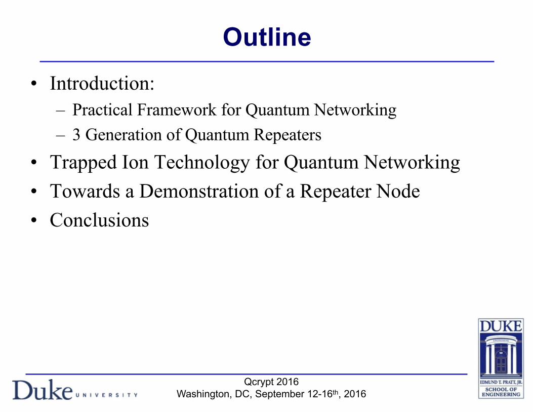
Evolution of Communication Networks
1st phone call, 1876NY-Chicago, 1892
Long-distance communication, 1915
Vacuum Tubes(First triode, 1907)
“Manual” switching networks, ~1950s
Modern telephone networks(WDM systems, 5ESS switches) ~1980s
Voice Dominates!
Distributed Computing(Data Centers)
GoogleGlobal InternetSince 1990s
Data Dominates!~QKD~Generic Q. Networks Tu Poster
Islam et al.
Qcrypt 2016Washington, DC, September 12-16th, 2016
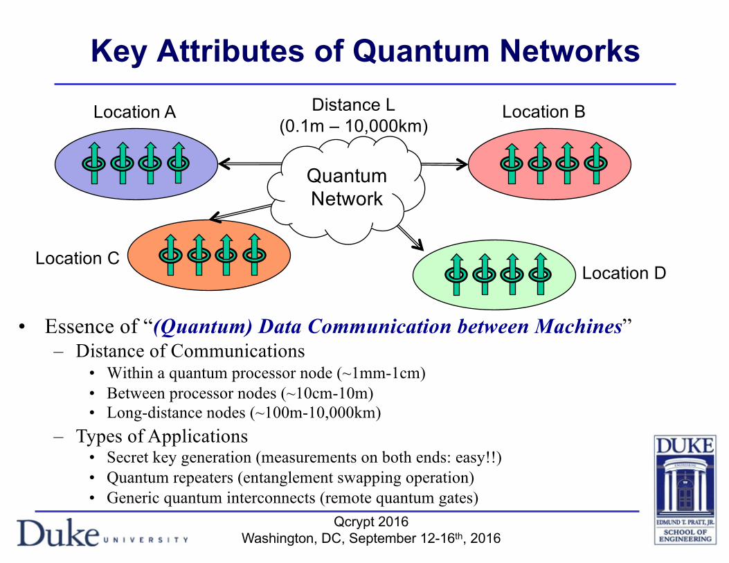
Key Attributes of Quantum Networks
• Essence of “(Quantum) Data Communication between Machines”– Distance of Communications
• Within a quantum processor node (~1mm-1cm)• Between processor nodes (~10cm-10m)• Long-distance nodes (~100m-10,000km)
Location A Location BDistance L(0.1m – 10,000km)
Location CLocation D
QuantumNetwork
– Types of Applications• Secret key generation (measurements on both ends: easy!!)• Quantum repeaters (entanglement swapping operation)• Generic quantum interconnects (remote quantum gates)
Qcrypt 2016Washington, DC, September 12-16th, 2016
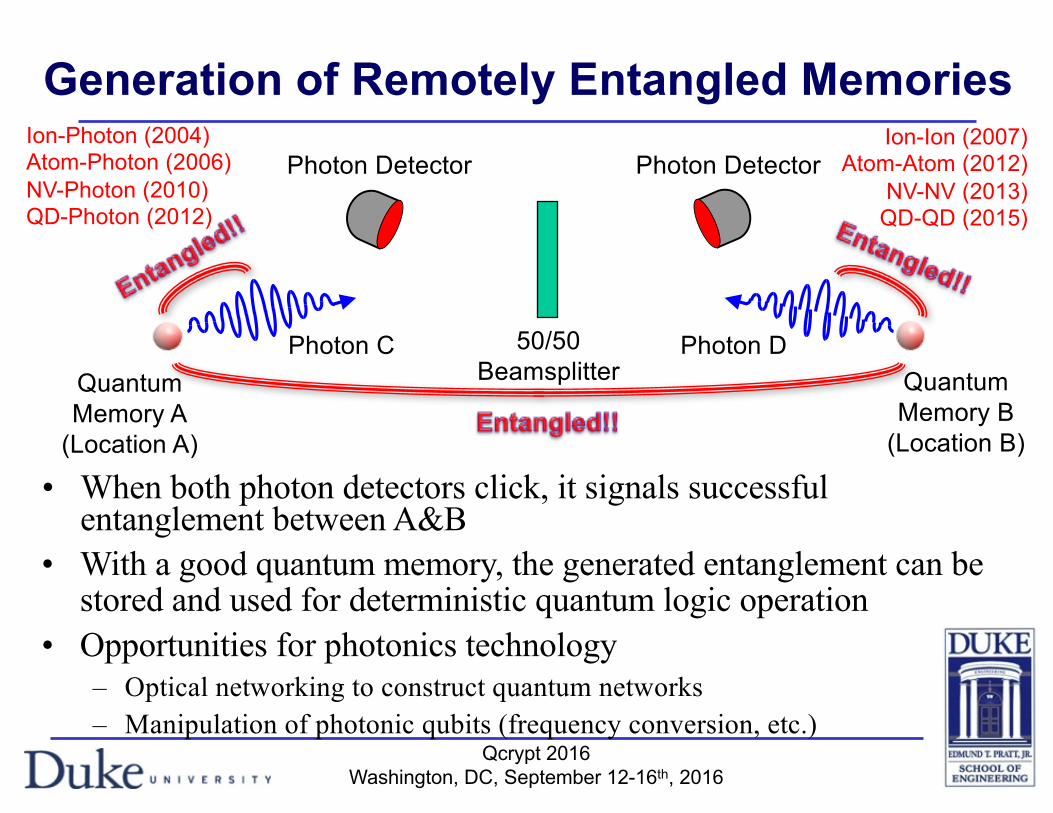
Generation of Remotely Entangled Memories
QuantumMemory A
(Location A)
QuantumMemory B
(Location B)
Photon C Photon D50/50Beamsplitter
Photon Detector Photon Detector
• With a good quantum memory, the generated entanglement can be stored and used for deterministic quantum logic operation
• Opportunities for photonics technology– Optical networking to construct quantum networks– Manipulation of photonic qubits (frequency conversion, etc.)
Ion-Photon (2004)Atom-Photon (2006)NV-Photon (2010)QD-Photon (2012)
Ion-Ion (2007)Atom-Atom (2012)
NV-NV (2013)QD-QD (2015)
• When both photon detectors click, it signals successful entanglement between A&B
Qcrypt 2016Washington, DC, September 12-16th, 2016
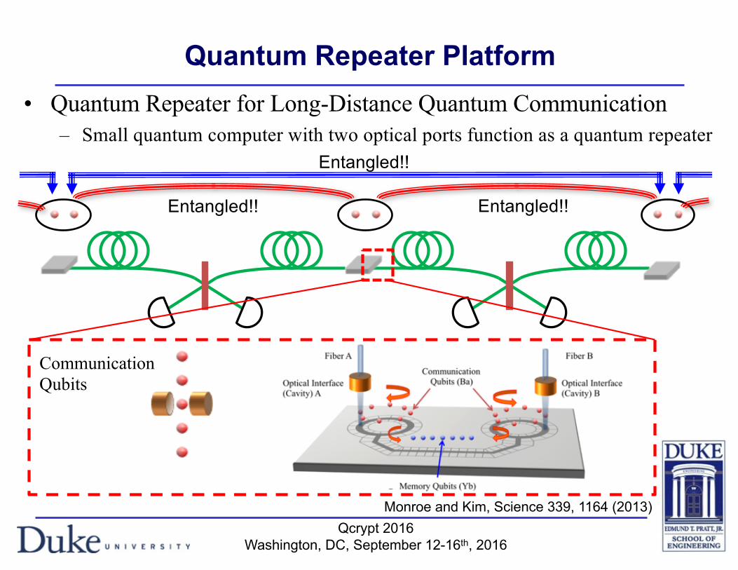
Quantum Repeater Platform• Quantum Repeater for Long-Distance Quantum Communication
– Small quantum computer with two optical ports function as a quantum repeater
Monroe and Kim, Science 339, 1164 (2013)
Communication Qubits
Nonlinear Quantum Wavelength Converter
Visible/UV Photon
Telecom Photon
Fiber Coupling Pump
Laser
Entangled!! Entangled!!
Entangled!!
Qcrypt 2016Washington, DC, September 12-16th, 2016
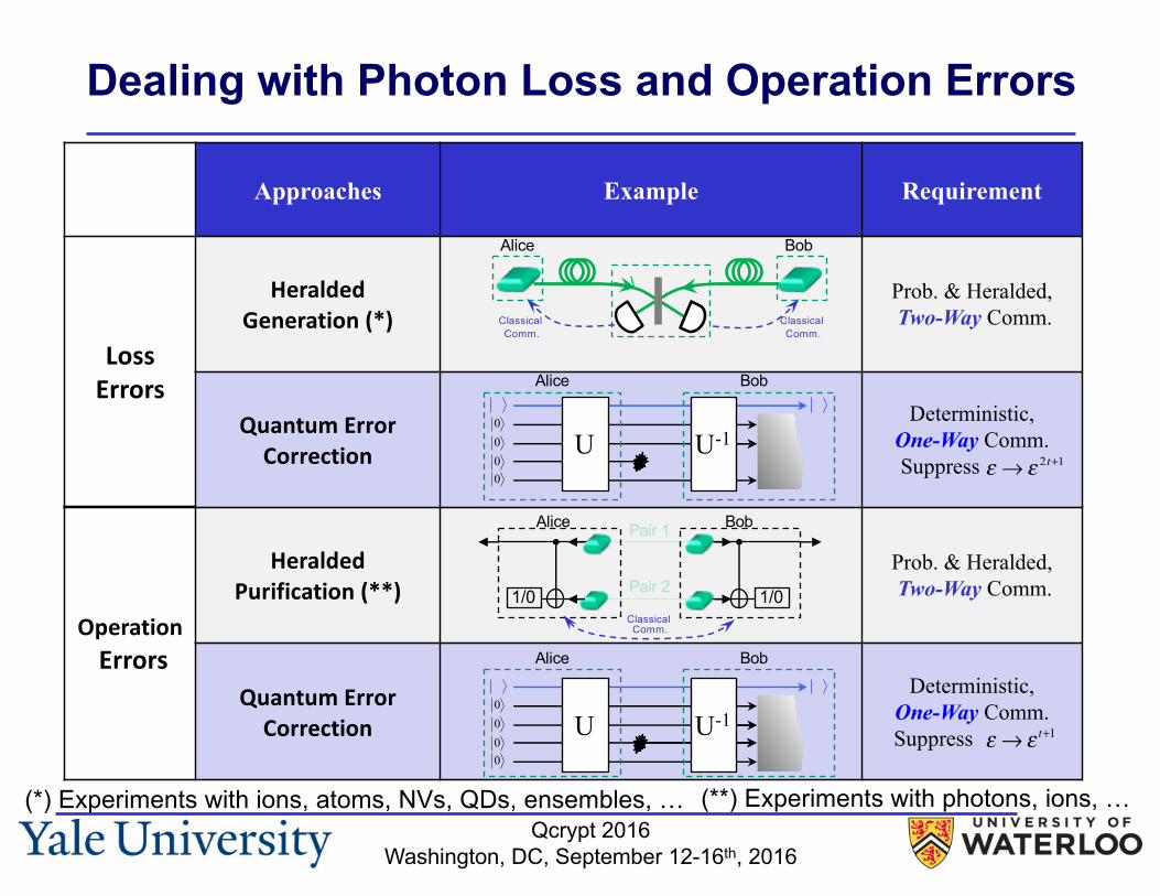
OperationErrors
HeraldedPurification(**)
Prob. & Heralded,Two-Way Comm.
QuantumErrorCorrection
Deterministic,One-Way Comm.Suppress
Dealing with Photon Loss and Operation Errors
Approaches Example Requirement
LossErrors
HeraldedGeneration(*)
Prob. & Heralded,Two-Way Comm.
QuantumErrorCorrection
Deterministic,One-Way Comm.Suppress
Classical Comm.
Classical Comm.
Alice Bob
1/0 1/0
Alice BobPair 1
Pair 2
Classical Comm.
0000
U U-1
0000
U U-1
Alice Bob
Alice Bob
(*) Experiments with ions, atoms, NVs, QDs, ensembles, … (**) Experiments with photons, ions, …
ε → ε 2t+1
ε → ε t+1

Qcrypt 2016Washington, DC, September 12-16th, 2016
Three Generations of QRs
Approaches 1st Generation 2nd Generation 3rd Generation
Loss Errors
Heralded Generation
[Two-Way Comm.]
Quantum ErrorCorrection
[One-Way Comm.]
Operation
Errors
HeraldedPurification
[Two-Way Comm.]
Quantum Error Correction
[One-Way Comm]
Muralidharan et al., PRL 112, 250501 (2014); Sci. Rep. 6, (2016)

Qcrypt 2016Washington, DC, September 12-16th, 2016
Outline• Introduction:
– Practical Framework for Quantum Networking– 3 Generation of Quantum Repeaters
• Trapped Ion Technology for Quantum Networking• Towards a Demonstration of a Repeater Node• Conclusions
Qcrypt 2016Washington, DC, September 12-16th, 2016
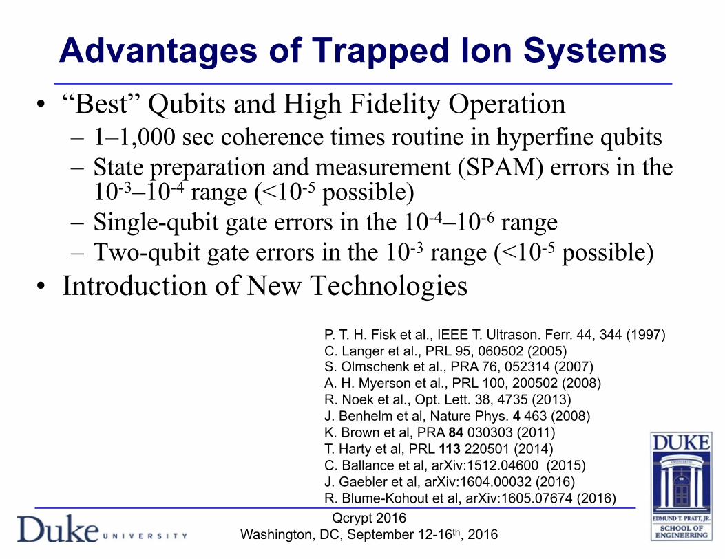
Advantages of Trapped Ion Systems• “Best” Qubits and High Fidelity Operation
– 1–1,000 sec coherence times routine in hyperfine qubits– State preparation and measurement (SPAM) errors in the
10-3–10-4 range (<10-5 possible)– Single-qubit gate errors in the 10-4–10-6 range– Two-qubit gate errors in the 10-3 range (<10-5 possible)
• Introduction of New TechnologiesP. T. H. Fisk et al., IEEE T. Ultrason. Ferr. 44, 344 (1997)C. Langer et al., PRL 95, 060502 (2005)S. Olmschenk et al., PRA 76, 052314 (2007)A. H. Myerson et al., PRL 100, 200502 (2008)R. Noek et al., Opt. Lett. 38, 4735 (2013)J. Benhelm et al, Nature Phys. 4 463 (2008)K. Brown et al, PRA 84 030303 (2011)T. Harty et al, PRL 113 220501 (2014)C. Ballance et al, arXiv:1512.04600 (2015)J. Gaebler et al, arXiv:1604.00032 (2016)R. Blume-Kohout et al, arXiv:1605.07674 (2016)
Qcrypt 2016Washington, DC, September 12-16th, 2016
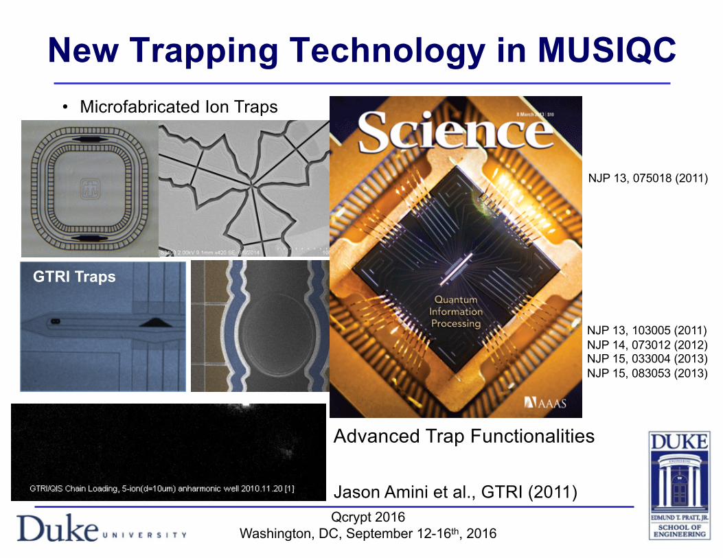
GTRI Traps
Sandia Traps
New Trapping Technology in MUSIQC• Microfabricated Ion Traps
Jason Amini et al., GTRI (2011)
Advanced Trap Functionalities
NJP 13, 103005 (2011)NJP 14, 073012 (2012)NJP 15, 033004 (2013)NJP 15, 083053 (2013)
NJP 13, 075018 (2011)

Qcrypt 2016Washington, DC, September 12-16th, 2016
High Optical Access (HOA) Trap
M1M2 M3
oxide
wafer silicon
4 µm waist is possible
< 2µm focus possible
Qcrypt 2016Washington, DC, September 12-16th, 2016
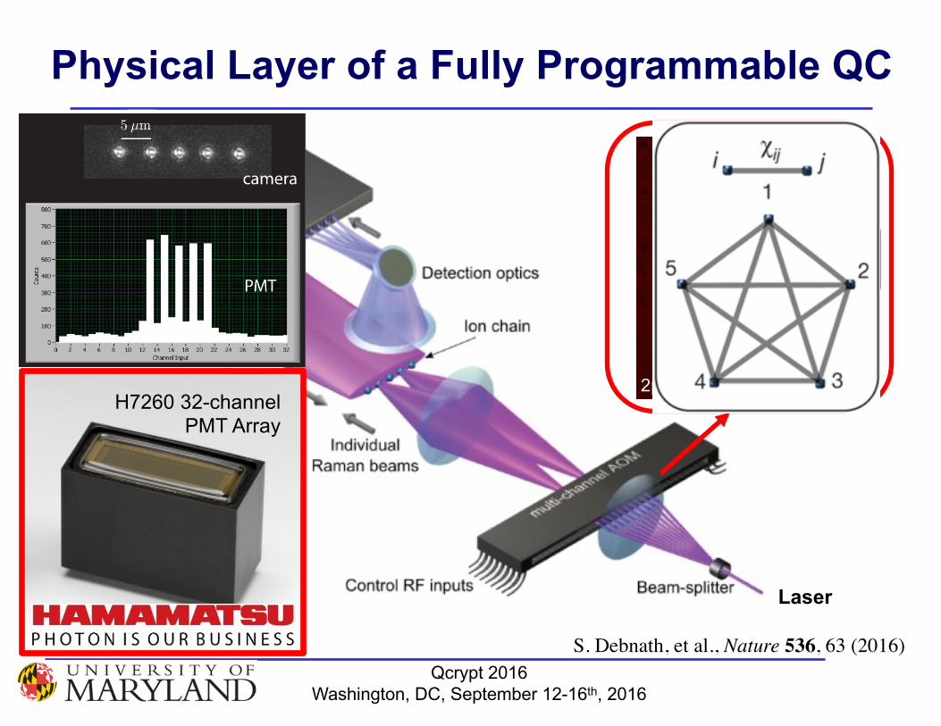
Harris Corp32channel
AOM2μm pixelsH7260 32-channel
PMT Array
Laser
S. Debnath, et al., Nature 536, 63 (2016)
Physical Layer of a Fully Programmable QC
Qcrypt 2016Washington, DC, September 12-16th, 2016
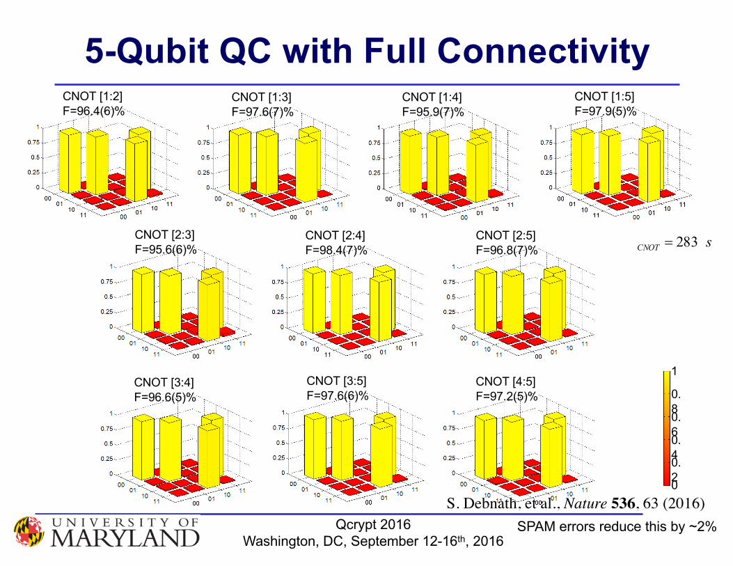
CNOT [1:2] F=96.4(6)%
CNOT [3:4] F=96.6(5)%
1
0
0.2
0.4
0.6
0.8
CNOT [1:3] F=97.6(7)%
CNOT [1:4] F=95.9(7)%
CNOT [1:5] F=97.9(5)%
CNOT [2:3] F=95.6(6)%
CNOT [2:4] F=98.4(7)%
CNOT [2:5] F=96.8(7)%
CNOT [3:5] F=97.6(6)%
CNOT [4:5] F=97.2(5)%
sCNOT 283=
SPAM errors reduce this by ~2%
5-Qubit QC with Full Connectivity
S. Debnath, et al., Nature 536, 63 (2016)
Qcrypt 2016Washington, DC, September 12-16th, 2016
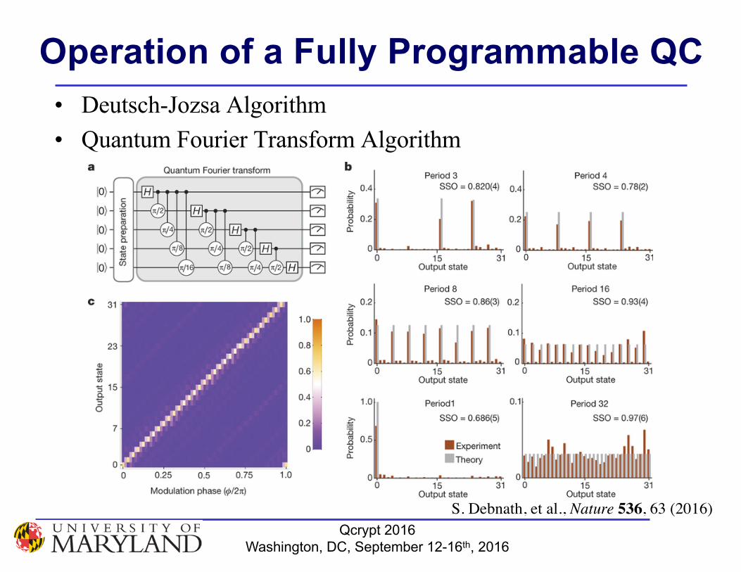
Operation of a Fully Programmable QC• Deutsch-Jozsa Algorithm• Quantum Fourier Transform Algorithm
S. Debnath, et al., Nature 536, 63 (2016)
Qcrypt 2016Washington, DC, September 12-16th, 2016
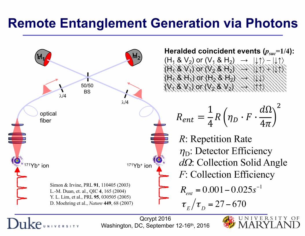
Remote Entanglement Generation via Photons
171Yb+ ion
opticalfiber
50/50BS
Simon & Irvine, PRL 91, 110405 (2003)L.-M. Duan, et. al., QIC 4, 165 (2004)Y. L. Lim, et al., PRL 95, 030505 (2005)D. Moehring et al., Nature 449, 68 (2007)
H1 V2Heralded coincident events (psuc=1/4):(H1 & V2) or (V1 & H2) → |↓↑ñ - |↓↑ñ(H1 & V1) or (V2 & H2) → |↓↑ñ + |↓↑ñ(H1 & H1) or (H2 & H2) → |↓↓ñ(V1 & V1) or (V2 & V2) → |↑↑ñ
l/4l/4
171Yb+ ion
V1 H2
Rent = 0.001− 0.025s−1
τ E τ D = 27−670
R: Repetition RatehD: Detector EfficiencydW: Collection Solid AngleF: Collection Efficiency
𝑅"#$ =14𝑅 𝜂) * 𝐹 *
𝑑Ω4𝜋
/

Qcrypt 2016Washington, DC, September 12-16th, 2016
Current Status on Entanglement Generation
171Yb+ ion
opticalfiber
50/50BS
H1 H2Heralded coincident events (psuc=1/2):(H1 & V2) or (V1 & H2) → |↓↑ñ - |↓↑ñ(H1 & V1) or (V2 & H2) → |↓↑ñ + |↓↑ñ(H1 & H1) or (H2 & H2) → |↓↓ñ(V1 & V1) or (V2 & V2) → |↑↑ñ
l/4l/4
50/50PBS
50/50PBS V1 V2
171Yb+ ion
R = 470kHz
p =ηD ⋅F ⋅dΩ4π
= (0.35)(0.14)(0.10)
Rent = 4.5s−1
Hucul et al, (UMD) Nature Phys. 11, 37 (2015)
NA 0.6 Lens
τ E τ D = 0.22s /1.12s = 0.20Simon & Irvine, PRL 91, 110405 (2003)L.-M. Duan, et. al., QIC 4, 165 (2004)Y. L. Lim, et al., PRL 95, 030505 (2005)D. Moehring et al., Nature 449, 68 (2007)Kim, Maunz & Kim, PRA 84, 063423 (2011)
𝑅"#$ =14𝑅 𝜂) * 𝐹 *
𝑑Ω4𝜋
/
Heralded coincident events (psuc=1/4):(H1 & V2) or (V1 & H2) → |↓↑ñ - |↓↑ñ(H1 & V1) or (V2 & H2) → |↓↑ñ + |↓↑ñ(H1 & H1) or (H2 & H2) → |↓↓ñ(V1 & V1) or (V2 & V2) → |↑↑ñ
𝑅"#$ =12𝑅 𝜂) * 𝐹 *
𝑑Ω4𝜋
/

Qcrypt 2016Washington, DC, September 12-16th, 2016
Fiber Coupling using High NA OpticsD. Hucul, et al., Nature Physics 11, 37 (2015)
ion #1
ion #2
success prob. per ion
trial rate
Parameter Jun 15 Jan 16 Ideal / Possible TechnologyhD 0.3 0.7 0.9 SNSPDF 0.2 0.49 0.8 PhotonGear Lens (alignment)Rent (per sec) 4.5 “150” 650
sec/5.421 2 == pRent
p =ηDFdΩ4π
= 0.5%
Γ = 600kHz
After gross correction After fine correction Airy Radius 135µm(Diffraction Limit)Waist in x: 176µmWaist in y: 217µm
J. Wong-Campos et al., Nat. Phot. (2016)
Qcrypt 2016Washington, DC, September 12-16th, 2016
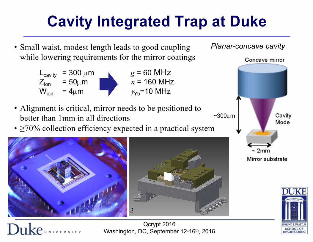
Planar-concave cavity
~300µm
• Small waist, modest length leads to good couplingwhile lowering requirements for the mirror coatings
• Alignment is critical, mirror needs to be positioned to better than 1mm in all directions
• ≥70% collection efficiency expected in a practical system
Cavity Integrated Trap at Duke
Lcavity = 300 µm g = 60 MHzZion = 50µm k = 160 MHz Wion = 4µm gYb=10 MHz
Qcrypt 2016Washington, DC, September 12-16th, 2016
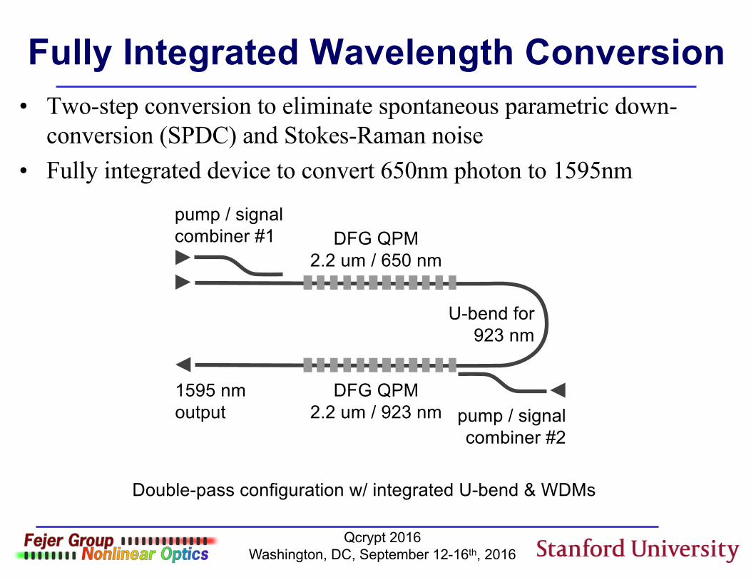
Fully Integrated Wavelength Conversion• Two-step conversion to eliminate spontaneous parametric down-
conversion (SPDC) and Stokes-Raman noise• Fully integrated device to convert 650nm photon to 1595nm
pump / signal combiner #1
pump / signal combiner #2
U-bend for 923 nm
DFG QPM2.2 um / 650 nm
DFG QPM2.2 um / 923 nm
1595 nm output
Double-pass configuration w/ integrated U-bend & WDMs
Qcrypt 2016Washington, DC, September 12-16th, 2016
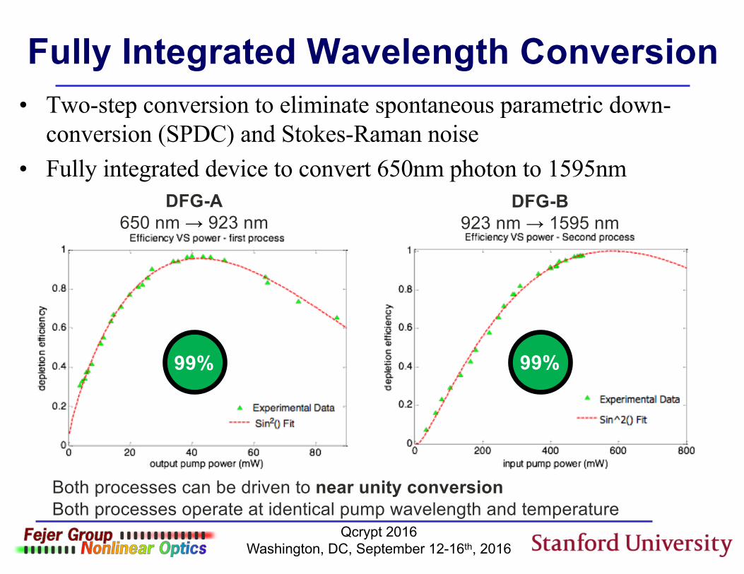
Fully Integrated Wavelength Conversion• Two-step conversion to eliminate spontaneous parametric down-
conversion (SPDC) and Stokes-Raman noise• Fully integrated device to convert 650nm photon to 1595nm
DFG-A650 nm → 923 nm
DFG-B923 nm → 1595 nm
Both processes can be driven to near unity conversion
99% 99%
Both processes operate at identical pump wavelength and temperature
Qcrypt 2016Washington, DC, September 12-16th, 2016
Outline• Introduction:
– Practical Framework for Quantum Networking– 3 Generation of Quantum Repeaters
• Trapped Ion Technology for Quantum Networking• Towards a Demonstration of a Repeater Node• Conclusions
Qcrypt 2016Washington, DC, September 12-16th, 2016
X
Z
12 1200 11+
34 3400 11+Z
X
Z
Z
Output “00” or “11”
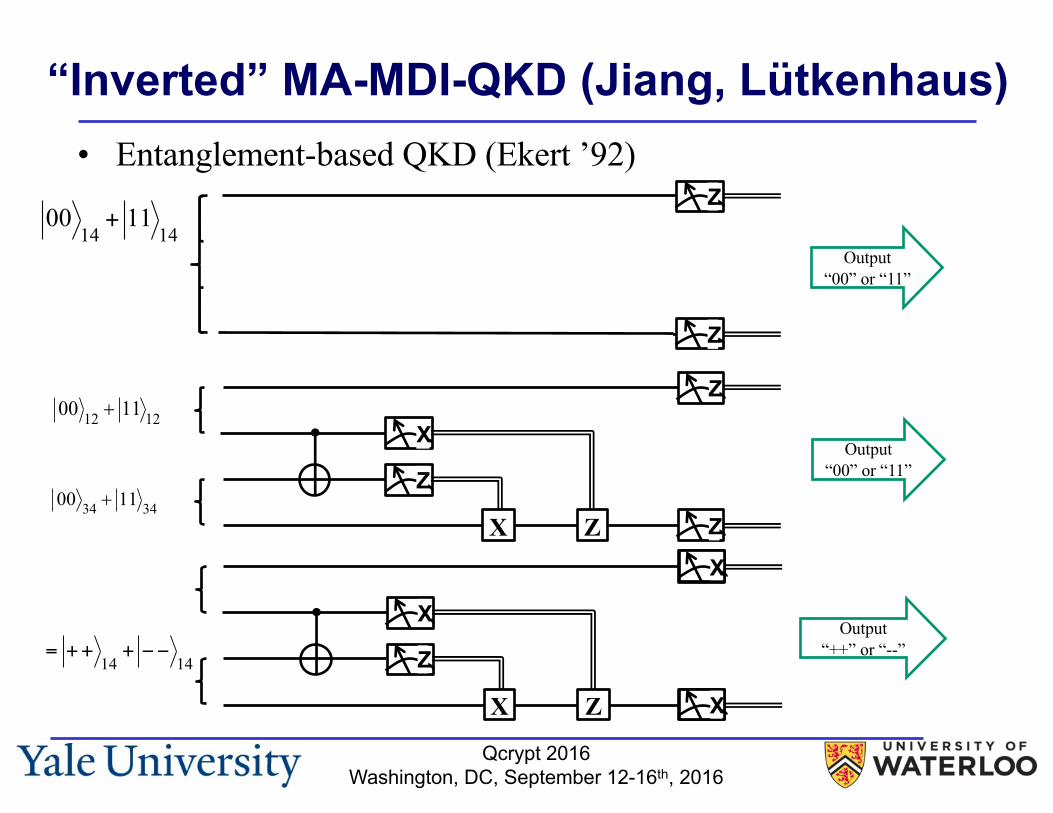
“Inverted” MA-MDI-QKD (Jiang, Lütkenhaus)• Entanglement-based QKD (Ekert ’92)
0014+ 11
14
X
Z
12 1200 11+
34 3400 11+Z
X
Z
Z
Output “00” or “11”
X
X
Output “++” or “--”
X
Z
12 1200 11+
34 3400 11+Z
X
X
X
= ++14+ −−
14
Qcrypt 2016Washington, DC, September 12-16th, 2016
X
Z
12 1200 11+
34 3400 11+Z
X
Z
Z
Output “00” or “11”
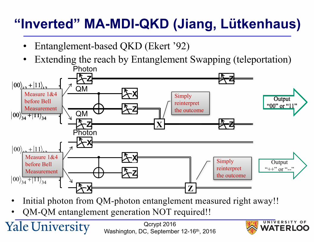
“Inverted” MA-MDI-QKD (Jiang, Lütkenhaus)• Entanglement-based QKD (Ekert ’92)• Extending the reach by Entanglement Swapping (teleportation)
X
Z
12 1200 11+
34 3400 11+Z
X
Z
Z
Output “00” or “11”
Output “00” or “11”
X12 1200 11+
34 3400 11+Z
Z
Z X
Simply reinterpret the outcome
Measure 1&4 before Bell Measurement
Simply reinterpret the outcome
X12 1200 11+
34 3400 11+Z
X
X Z
Output “++” or “--”
Measure 1&4 before Bell Measurement
• Initial photon from QM-photon entanglement measured right away!!• QM-QM entanglement generation NOT required!!
Photon
Photon
QM
QM
Qcrypt 2016Washington, DC, September 12-16th, 2016
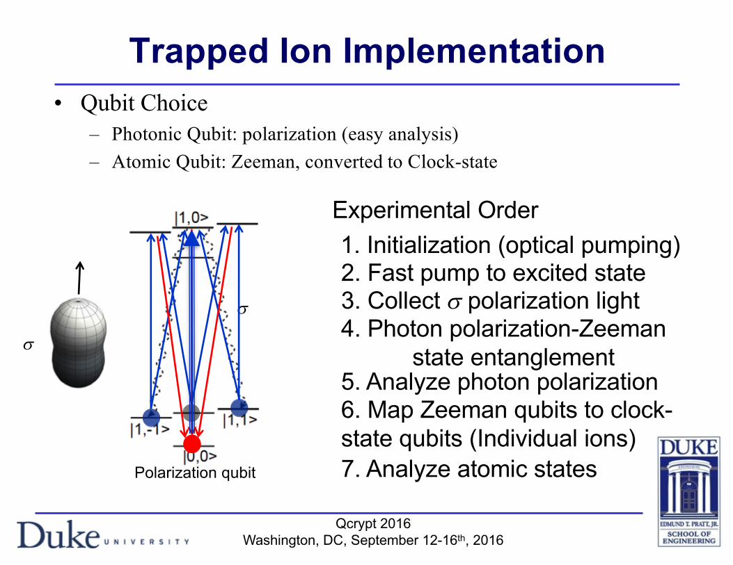
Trapped Ion Implementation• Qubit Choice
– Photonic Qubit: polarization (easy analysis)– Atomic Qubit: Zeeman, converted to Clock-state
Polarization qubit
s
s
Experimental Order1. Initialization (optical pumping)2. Fast pump to excited state3. Collect s polarization light4. Photon polarization-Zeeman
state entanglement5. Analyze photon polarization6. Map Zeeman qubits to clock-state qubits (Individual ions)7. Analyze atomic states
Qcrypt 2016Washington, DC, September 12-16th, 2016
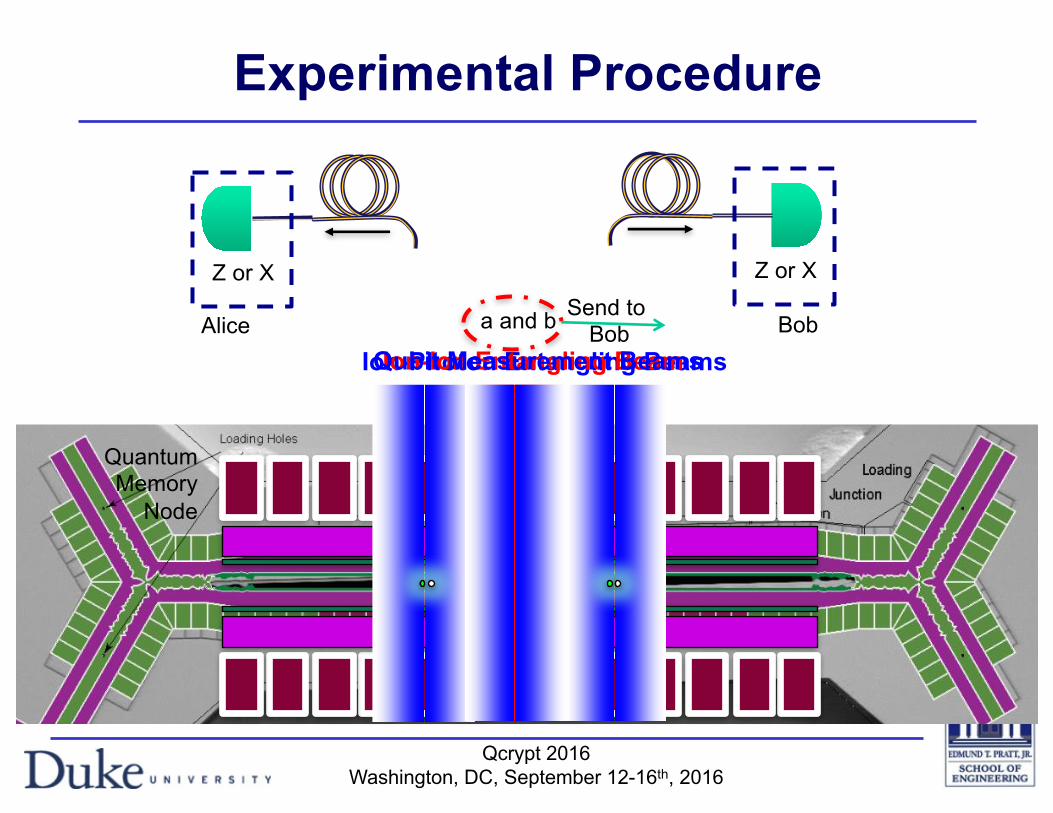
Experimental Procedure
Page | 6
1.3 Trap topology An SEM/schematic image of the HOA trap is shown in Figure 4. The device is broken out into 4 types of regions:
1. a “quantum” region which is useful for transverse gates because of the slot underneath the trap and the strong trapping potential;
2. a “transition” region which connects the slotted and un-slotted parts of the trap 3. a “junction” region which can be used for re-ordering ions in the quantum region; 4. and a “loading” region which has a loading hole for backside ion loading. Note that the slotted
quantum region can also be used for loading if convenient.
Figure 4: SEM image of the HOA trap with overlaid electrode coloring to indicate the intended functionality of each section.
1.4 Integrated optics One of the designed add-ons for the HOA 1.0 trap is an integrated optic. SNL designed a Diffractive Optical Element (DOE) which could image one end of the quantum region while retaining a high NA imaging capability at the other end. A birds-eye schematic of this is shown in Figure 5 and an image of the assembled system is shown in Figure 6. This is not a standard component of the HOA trap.
Ion-Photon Entangling BeamsIon-Ion Entangling BeamQubit Measurement Beams
QuantumMemory
Node
Bob
Z or X
Alice
Z or XSend to
Boba and b
Qcrypt 2016Washington, DC, September 12-16th, 2016
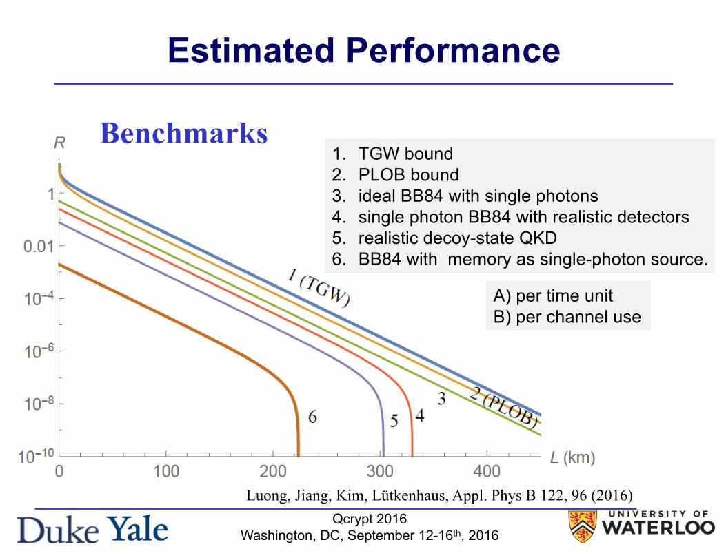
Estimated Performance
Benchmarks1. TGW bound2. PLOB bound3. ideal BB84 with single photons4. single photon BB84 with realistic detectors5. realistic decoy-state QKD6. BB84 with memory as single-photon source.
A) per time unitB) per channel use
Luong, Jiang, Kim, Lütkenhaus, Appl. Phys B 122, 96 (2016)
Qcrypt 2016Washington, DC, September 12-16th, 2016
Overcoming lossy channel bounds using a single quantum repeater node
1 3
Page 7 of 10 96
6.2 Beating direct transmission
We are now in a position to determine the conditions under which our protocol can beat the direct transmission bench-marks listed in Sect. 3. First, note that at L = 0 the perfor-mance of our protocol may be worse than that of the bench-marks because the central station introduces additional sources of loss. However, because the key rate for our pro-tocol scales better with distance than the benchmark key rates when L is not too large, crossover with one or more of them is possible at some L > 0.
When the central station position is optimized, crossover can only occur in the e−L/(2Latt) regime (excluding marginal cases)—that is, when the optimal position is near the mid-point between Alice and Bob. Equivalently, crossover can only occur when the unoptimized key rate is nonzero. For this reason, we will fix the central station at L / 2 for the remainder of this section instead of optimizing its posi-tion. It is worth mentioning that crossover with a certain benchmark does not mean that our protocol beats it for all L beyond the crossover point; the interval over which our protocol is superior may be quite small. But optimizing the central station position can potentially increase the range of distances over which our protocol beats the benchmark compared to the leaving the station at L / 2.
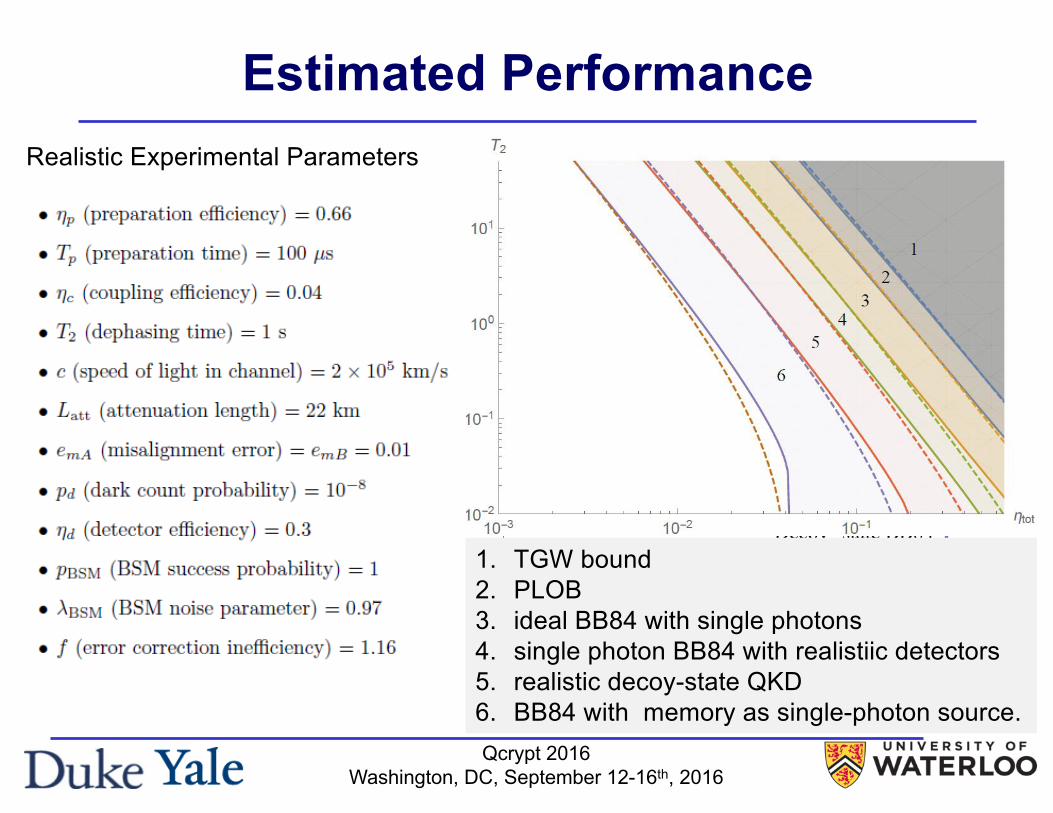
We identify two parameters, the combined efficiency ηtot and the dephasing time T2, which are crucial in determining whether crossover occurs with any of the benchmarks and which can be improved from the values given at the begin-ning of this section. For example, the photon-fiber coupling efficiency in ηc could be pushed from 0.04 to as high as 0.3 [21] (leading to ηtot = 0.0178), while a T2 of 50 s has already been demonstrated [22]. Figure 6 shows the regions
in ηtot-T2 space in which we can beat each of the bench-marks. It is clear from the figure that we cannot beat any of the benchmarks with the parameters given at the beginning of the section, and that from our perspective, improving ηtot is more likely to result in crossover than improving T2.
Each region may be explained in the following way. When L is small enough for errors to be negligible, the key rate of our protocol is R ≈ R0e
−L/(2Latt) while that of the benchmark of interest is Rb ≈ Rb,0e
−L/Latt, where R0 and Rb,0 are the key rates at L = 0 of our protocol and of the benchmark respectively.1 These curves intersect at a dis-tance Lint. If Lint is smaller than some characteristic dis-tance Ldp beyond which dephasing becomes significant, then there is a crossover. The boundary of the crossover region corresponds to Lint = Ldp. These ideas are illustrated in Fig. 7.
Based on this explanation, we can derive an approximate formula for the boundary of the region in which crossover occurs with a given benchmark with key rate Rb:
Here
Rηtot=10 denotes the key rate of our protocol when L = 0 and
ηtot = 1, and K is a fitting parameter characterizing how
1 This does not quite apply to the TGW bound, which goes to infinity as L → 0. In this case, one must continue the e−L/Latt behavior all the way to L = 0, so that Rb,0 = 2/ ln 2.
(25)T2 = K
!
QTp
η2tot+
2Latt ln(Q/ηtot)
c
"
1+Q
η2tot
#$
.
(26)Q =3Rb,0
2Rηtot=10
,
Fig. 6 Shaded regions indicate values of ηtot and T2 for which our protocol beats each of the benchmarks listed in Sect. 3. Dashed lines indicate approximations to the boundaries of these regions obtained using (25). For benchmark 5 (quantum memory as single-photon source), we have fixed ηc = 0.3 × 0.3
Fig. 7 Approximating the crossover point using the scaling behavior of the key rates. Note that the intersection point of the approximating curves coincides with the crossover point of the key rate curves, and that the intersection occurs before dephasing becomes significant and the key rate of our protocol goes to 0. (We have set ηc = 0.3.)
Estimated Performance
1. TGW bound2. PLOB3. ideal BB84 with single photons4. single photon BB84 with realistiic detectors5. realistic decoy-state QKD6. BB84 with memory as single-photon source.
Realistic Experimental Parameters
Qcrypt 2016Washington, DC, September 12-16th, 2016
Conclusions• Trapped ion platform is a compelling candidate for
realizing quantum repeaters– Good memory-photon interface– “Full blown” quantum computer with deterministic gate
operations is available– Performance enhancement efforts are on the way
• Demonstration of “useful” quantum repeater remains a challenge, yet within reach!!– Overall system efficiencies need dramatic improvements– Necessary technologies are under development– System integration will require substantial effort
Qcrypt 2016Washington, DC, September 12-16th, 2016
Team and Collaboration• Duke Team
Peter MaunzTaehyun KimSo-Young BaekKai HudekRachel NoekEmily MountDaniel GaultneyStephen CrainCaleb KnoernschildAndre van RynbachGeert VrijsenYuhi AikyoClinton CahallChao FangRobert “Tripp” SpiveyGeorge SchwartzSarah BrandsenSeo Ho YounJinhyun ChoKyle McKayHui SonRyan ClarkMuhammed AhsanJohn Montoya
• University of MarylandChris MonroeJonathan MizrahiMarko CetinaJason AminiNorbert LinkeKen WrightShantanu DebnathKale JohnsonDavid Wong-CamposDavid HuculVolkan InlekAaron Lee
• Yale UniversityLiang JiangSre MuralidharanLinshu Li
• University of WaterlooNorbert LütkenhausDavid LuongRyo NamikiFilippo Miato
• Stanford UniversityMartin FejerCarsten LangrockVahid Esfandyarpour
• Sandia National LabsPeter MaunzChristian ArringtonDrew Hollowell
• NISTSae Woo NamVarun Verma
• JPLMatthew ShawFrancesco MarsiliEmma Wollman
Recommended

![Quantum simulation of the transverse Ising model with trapped …site.physics.georgetown.edu/.../ion_trap_review_njp_2011.pdf · 2016-04-05 · trapped atomic ions [12–21], neutral](https://img.pdfslide.us/doc/110x75/5f0ad1947e708231d42d7eb9/quantum-simulation-of-the-transverse-ising-model-with-trapped-site-2016-04-05.jpg)