
designKilla:designKilla:The 32-bit pipelined processorThe 32-bit pipelined processor
Brought to you by:Brought to you by:
Victoria FarthingVictoria Farthing
Dat HuynhDat Huynh
Jerry FelkerJerry Felker
Tony ChenTony ChenSupervisor: Young Cho
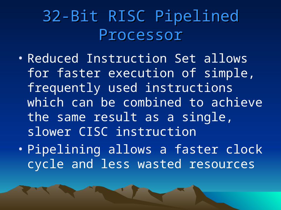
32-Bit RISC Pipelined Processor32-Bit RISC Pipelined Processor
• Reduced Instruction Set allows for faster execution of simple, frequently used instructions which can be combined to achieve the same result as a single, slower CISC instruction
• Pipelining allows a faster clock cycle and less wasted resources
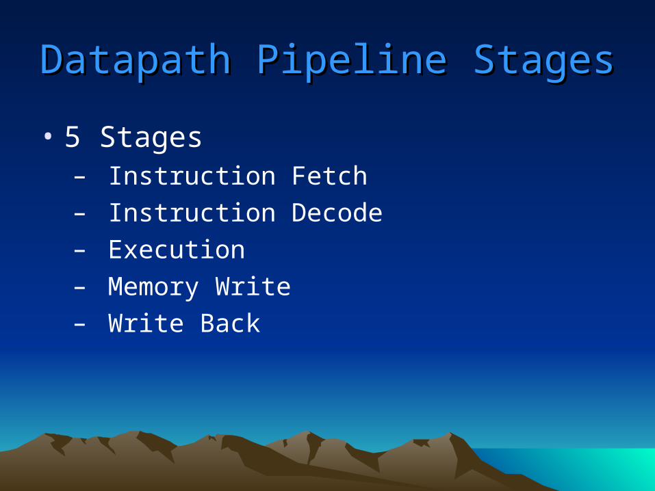
Datapath Pipeline StagesDatapath Pipeline Stages
• 5 Stages– Instruction Fetch– Instruction Decode– Execution– Memory Write– Write Back
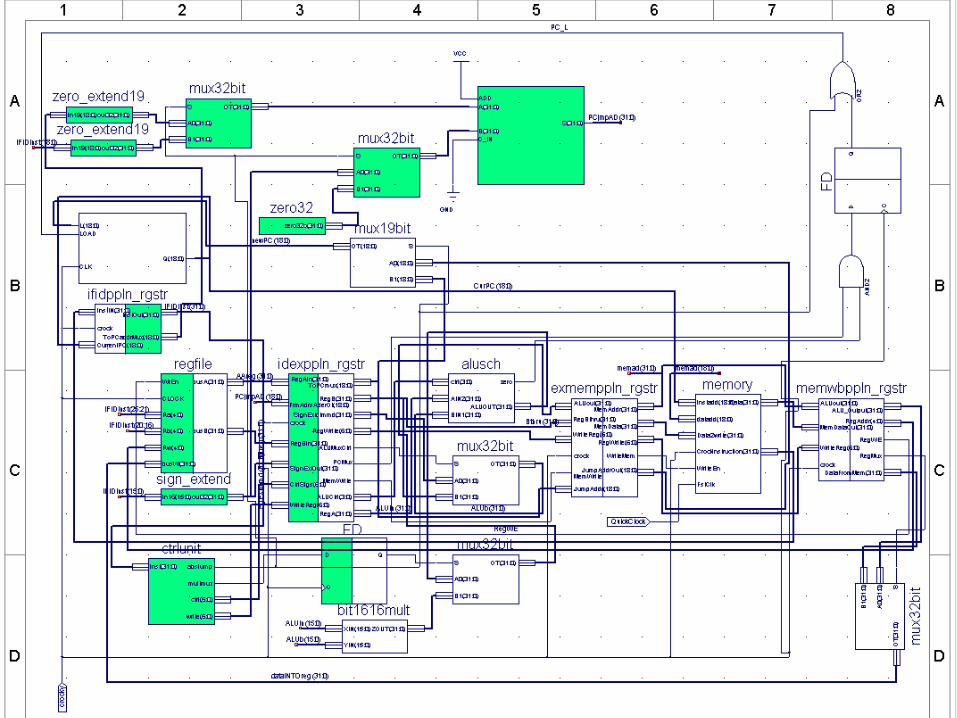
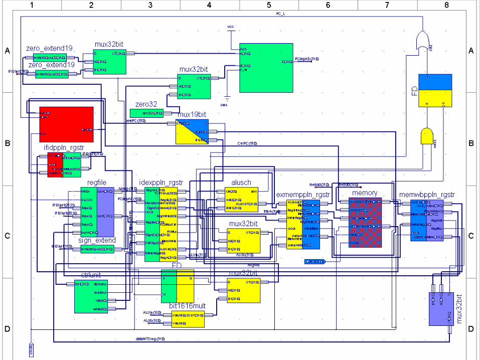
Unique Data Path FeaturesUnique Data Path Features
• Next instruction address calculation– For basic incrementation, the address is
calculated by a counter
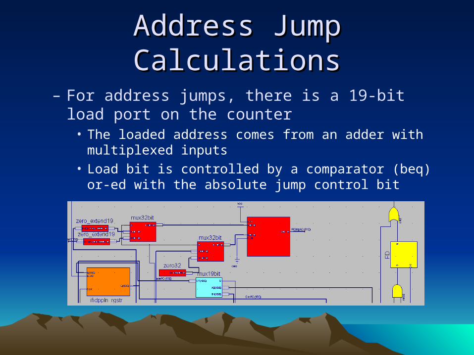
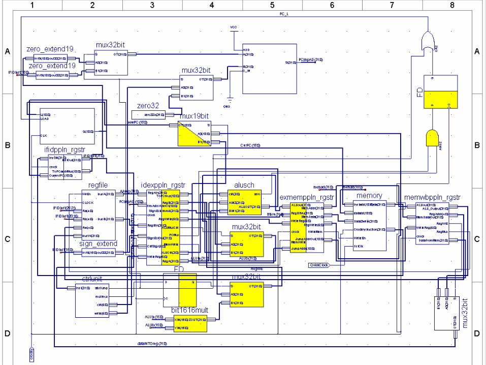
Address Jump CalculationsAddress Jump Calculations
– For address jumps, there is a 19-bit load port on the counter
• The loaded address comes from an adder with multiplexed inputs
• Load bit is controlled by a comparator (beq) or-ed with the absolute jump control bit
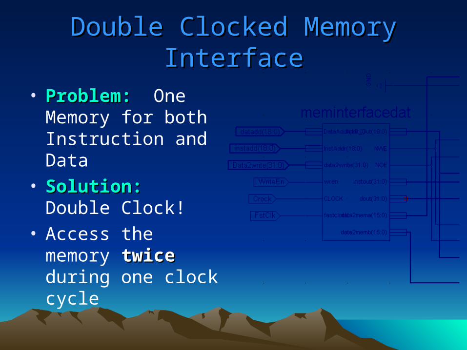
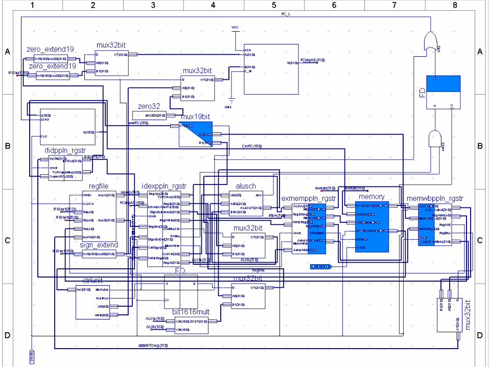
Double Clocked Memory InterfaceDouble Clocked Memory Interface
• Problem:Problem: One Memory for both Instruction and Data
• Solution:Solution: Double Clock!
• Access the memory twicetwice during one clock cycle
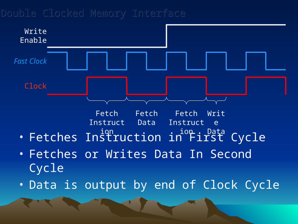
Fast Clock
Clock
Fetch Instruction
Fetch Data Fetch Instruction
Write Enable
Write Data
Double Clocked Memory InterfaceDouble Clocked Memory Interface
• Fetches Instruction in First Cycle• Fetches or Writes Data In Second Cycle• Data is output by end of Clock Cycle
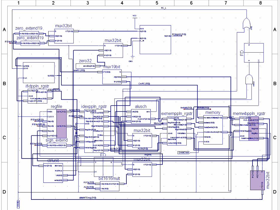
Unique Data Path FeaturesUnique Data Path Features
• Structural Multiplier– 16 X 16 bit– Multi-level creation:
• Four 8 X 8 bit multipliers– Each containing four 4 X 4 bit multipliers
• Each comprised of a cascaded network of full and half adders, built on logic gates
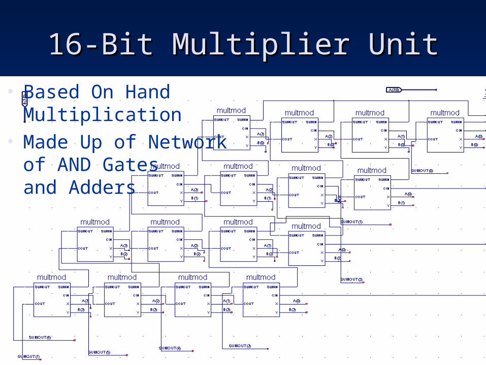
16-Bit Multiplier Unit16-Bit Multiplier Unit
• Based On Hand Multiplication• Made Up of Network
of AND Gatesand Adders
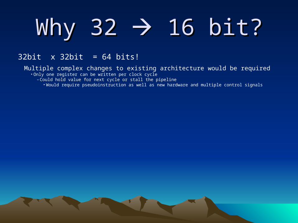
Why 32 Why 32 16 bit? 16 bit?32bit x 32bit = 64 bits!
Multiple complex changes to existing architecture would be required• Only one register can be written per clock cycle
– Could hold value for next cycle or stall the pipeline• Would require pseudoinstruction as well as new hardware and multiple control signals
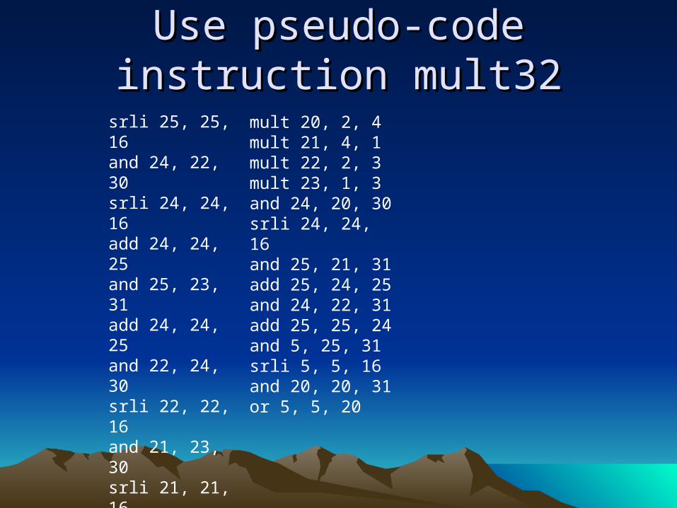
Use pseudo-code instruction Use pseudo-code instruction mult32mult32
mult 20, 2, 4mult 21, 4, 1mult 22, 2, 3mult 23, 1, 3and 24, 20, 30srli 24, 24, 16and 25, 21, 31add 25, 24, 25and 24, 22, 31add 25, 25, 24and 5, 25, 31srli 5, 5, 16and 20, 20, 31or 5, 5, 20
srli 25, 25, 16and 24, 22, 30srli 24, 24, 16add 24, 24, 25and 25, 23, 31add 24, 24, 25and 22, 24, 30srli 22, 22, 16and 21, 23, 30srli 21, 21, 16add 6, 21, 22slli 6, 6, 16and 24, 24, 31or 6, 6, 24
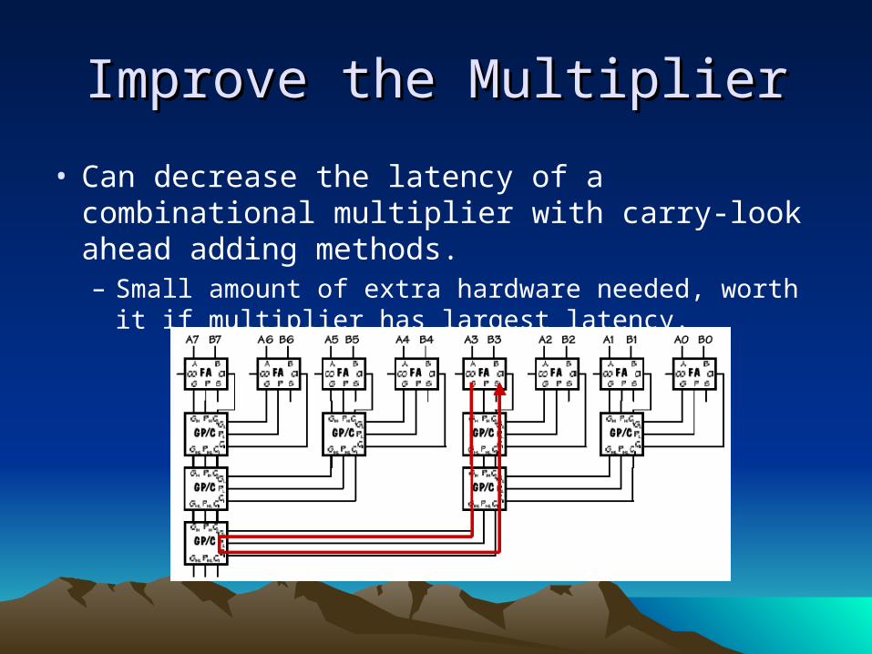
Improve the MultiplierImprove the Multiplier
• Can decrease the latency of a combinational multiplier with carry-look ahead adding methods.– Small amount of extra hardware needed, worth it if
multiplier has largest latency.
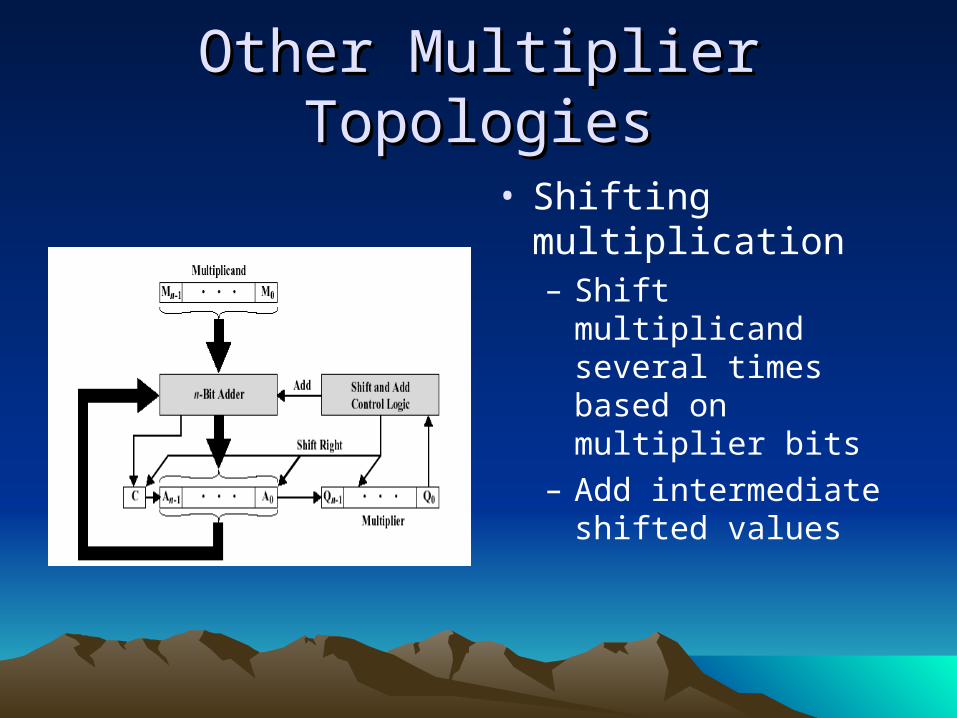
Other Multiplier TopologiesOther Multiplier Topologies
• Shifting multiplication– Shift multiplicand
several times based on multiplier bits
– Add intermediate shifted values

Other Multiplier TopologiesOther Multiplier Topologies
• Pipelined multiplication– Store intermediate sums– Allows for faster clock
cycle if traditional combinational multiplication presents the critical path
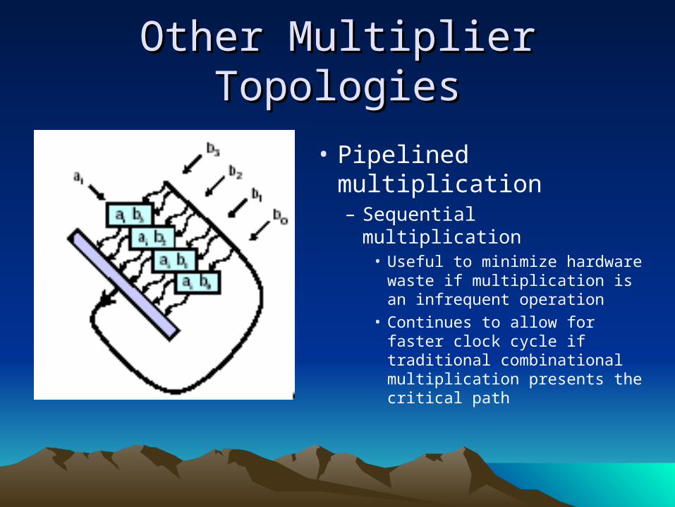
Other Multiplier TopologiesOther Multiplier Topologies
• Pipelined multiplication– Sequential multiplication
• Useful to minimize hardware waste if multiplication is an infrequent operation
• Continues to allow for faster clock cycle if traditional combinational multiplication presents the critical path
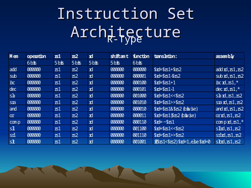
Instruction Set ArchitectureInstruction Set Architecture
Mem operation rs1 rs2 rd shift amt function translation: assembly6 bits 5 bits 5 bits 5 bits 5 bits 6 bits
add 000000 rs1 rs2 rd 000000 000000 $rd=$rs1+$rs2 add rd, rs1, rs2sub 000000 rs1 rs2 rd 000000 000001 $rd=$rs1-$rs2 sub rd, rs1, rs2inc 000000 rs1 rs2 rd 000000 000100 $rd=$rs1+1 inc rd, rs1, *dec 000000 rs1 rs2 rd 000000 000101 $rd=$rs1-1 dec rd, rs1, *sla 000000 rs1 rs2 rd 000000 001000 $rd=$rs1<<$rs2 sla rd, rs1, rs2sra 000000 rs1 rs2 rd 000000 001010 $rd=$rs1>>$rs2 sra rd, rs1, rs2and 000000 rs1 rs2 rd 000000 000010 $rd=$rs1&$rs2 (bitwise) and rd, rs1, rs2or 000000 rs1 rs2 rd 000000 000011 $rd=$rs1|$rs2 (bitwise) or rd, rs1, rs2comp 000000 rs1 rs2 rd 000000 000110 $rd= ~$rs1 comp rd, rs1, *sll 000000 rs1 rs2 rd 000000 001100 $rd=$rs1<<$rs2 sll rd, rs1, rs2srl 000000 rs1 rs2 rd 000000 001110 $rd=$rs1>>$rs2 srl rd, rs1, rs2slt 000000 rs1 rs2 rd 000000 001001 if($rs1<$rs2) $rd=1, else $rd=0 slt rd, rs1, rs2
R-Type
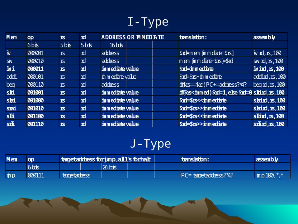
Mem op rs rd ADDRESS OR IMMEDIATE translation: assembly6 bits 5 bits 5 bits 16 bits
lw 000001 rs rd address $rd=mem[immdiate+$rs] lw rd, rs, 100sw 000010 rs rd address mem[immdiate+$rs]=$rd sw rd, rs, 100lwi 000011 rs rd immediate value $rd=immediate lwi rd, rs, 100addi 000101 rs rd immediate value $rd=$rs+immediate addi rd, rs, 100beq 000110 rs rd address if($rs==$rd) PC+=address?*4? beq rd, rs, 100slti 001001 rs rd immediate value if($rs<immed) $rd=1, else $rd=0 slti rd, rs, 100slai 001000 rs rd immediate value $rd=$rs<<immediate slai rd, rs, 100srai 001010 rs rd immediate value $rd=$rs>>immediate slai rd, rs, 100slli 001100 rs rd immediate value $rd=$rs<<immediate slli rd, rs, 100srli 001110 rs rd immediate value $rd=$rs>>immediate srli rd, rs, 100
I-Type
Mem op target address for jump, all 1's for halt translation: assembly6 bits 26 bits
jmp 000111 target adress PC= target address?*4? jmp 100, *, *
J-Type
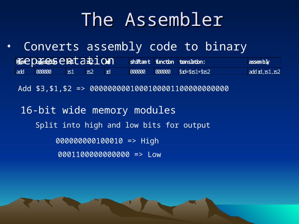
• Converts assembly code to binary representation
The AssemblerThe Assembler
add 000000 rs1 rs2 rd 000000 000000 $rd=$rs1+$rs2 add rd, rs1, rs2
Mem operation rs1 rs2 rd shift amt function translation: assembly
Add $3,$1,$2 => 0000000001000100001100000000000
000000000100010 => High
0001100000000000 => Low
16-bit wide memory modules
Split into high and low bits for output
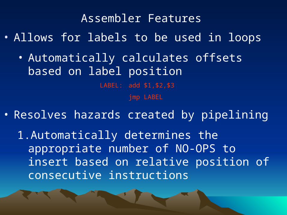
• Allows for labels to be used in loops
• Automatically calculates offsets based on label position
LABEL: add $1,$2,$3
jmp LABEL
• Resolves hazards created by pipelining
1.Automatically determines the appropriate number of NO-OPS to insert based on relative position of consecutive instructions
Assembler Features
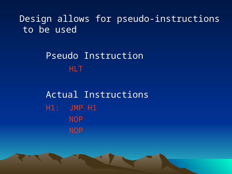
Design allows for pseudo-instructions to be used
Pseudo Instruction
HLT
Actual Instructions
H1: JMP H1
NOP
NOP
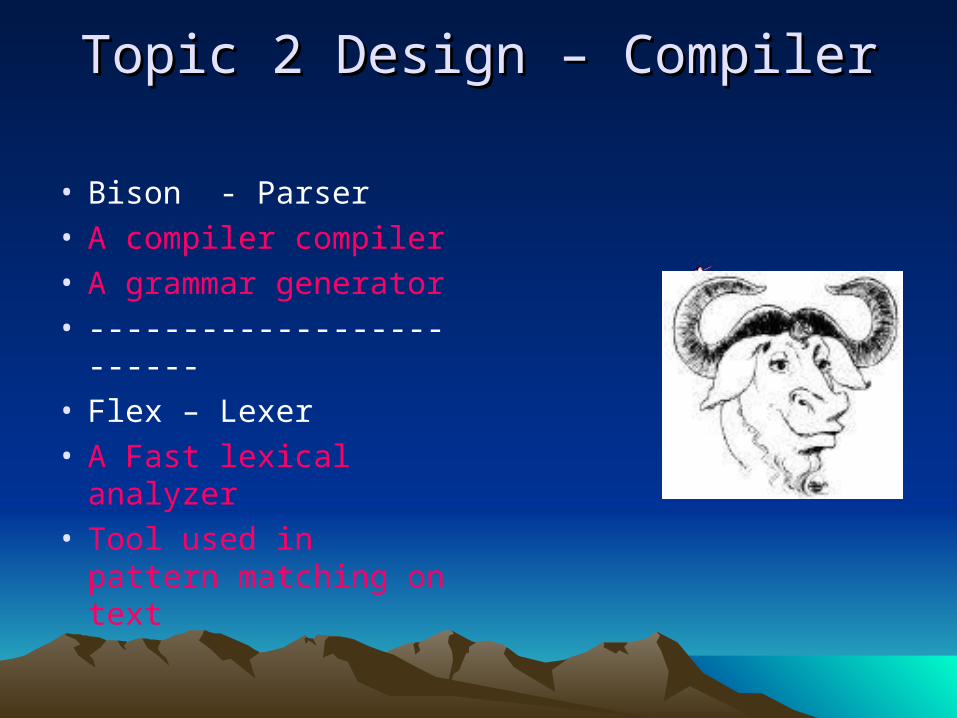
Topic 2 Design – CompilerTopic 2 Design – Compiler
• Bison - Parser• A compiler compiler• A grammar generator• -------------------------• Flex – Lexer• A Fast lexical
analyzer• Tool used in pattern
matching on text
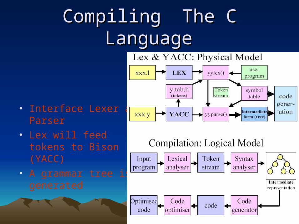
CompilingCompiling The C LanguageThe C Language
• Interface Lexer and Parser
• Lex will feed tokens to Bison (YACC)
• A grammar tree is generated
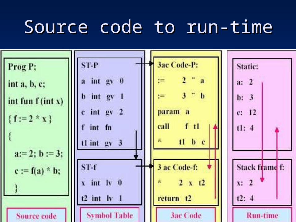
Source code to run-timeSource code to run-time
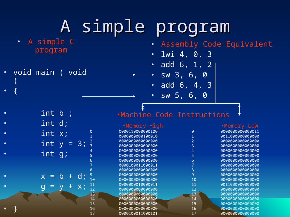
A simple programA simple program• A simple C program
• void main ( void )• {
• int b ;• int d;• int x;• int y = 3;• int g;
• x = b + d;• g = y + x;
• }
• Assembly Code Equivalent• lwi 4, 0, 3• add 6, 1, 2• sw 3, 6, 0• add 6, 4, 3• sw 5, 6, 0
•Memory High0 00001100000001001 00000000001000102 00000000000000003 00000000000000004 00000000000000005 00000000000000006 00000000000000007 00001000110000118 00000000000000009 000000000000000010 000000000000000011 000000001000001112 000000000000000013 000000000000000014 000000000000000015 000000000000000016 000000000000000017 0000100011000101
•Memory Low0 00000000000000111 00110000000000002 00000000000000003 00000000000000004 00000000000000005 00000000000000006 00000000000000007 00000000000000008 00000000000000009 000000000000000010 000000000000000011 001100000000000012 000000000000000013 000000000000000014 000000000000000015 000000000000000016 000000000000000017 0000000000000000
•Machine Code Instructions

Could Use a Little WorkCould Use a Little Work
• Currently the Processor could use a little work to improve performance.– Decreased memory latency would be largest
and most direct improvement to processor.– Must optimize ALU as well as multiplier unit.– All in all, will work but not ready for
commercial usage.
ReferencesReferencesComputer Organization and Design: The Hardware Software Interface (2nd Ed)
Patterson, David A. and Hennessy, John L.
Morgan Kaufman Publishers, 1997
Introduction to Compilers
http://cs.wwc.edu/~aabyan/221_2/PLBOOK/Translation.html
Aaby, Anthony A., 1998
The Compiler Design Handbook
Srikant, Y. N. and Shankar, Priti
CRC Press, 2002

THE ENDTHE END
Questions?Questions?
Recommended