Department of Mechanical Engineering
Design Review 4
Team 507 - SAE Aero Design – Aero and Propulsion Team
1
Department of Mechanical Engineering
Team Introductions
Cameron Riley: Materials/Hardware Engineer
Adrian Moya: Systems/Hardware Engineer
Sasindu Pinto: Project /Aeronautics/Propulsion Engineer
Noah Wright: Aerodynamics Engineer
Michenell Louis-Charles: Thermal Fluids Engineer/Financial Chair
2

Department of Mechanical Engineering
Sponsor and Advisors
Dr. Chiang Shih:Professor & AME Center Director Advisor
Seminole RC Club:Equipment/Personnel Sponsor
Florida Space Grant Consortium:Funding Sponsor
Presenter: AM
3

4Department of Mechanical Engineering
Team Objective
The objective of the aero-propulsion team is to ensure that the plane takes off and lands while carrying a payload while completing the flight path.
Presenter: AM

5Department of Mechanical Engineering
Key Definitions
Presenter: AM
Lift
Weight
Y
X

6Department of Mechanical Engineering
Key Definitions
Presenter: AM
Thrust
Drag
Y
X

7Department of Mechanical Engineering
Presenter: AM
Key Definitions
Pitch
Y
XZ

8Department of Mechanical Engineering
Presenter: AM
Key Definitions
Yaw
Z
XY
9Department of Mechanical Engineering
Presenter: AM
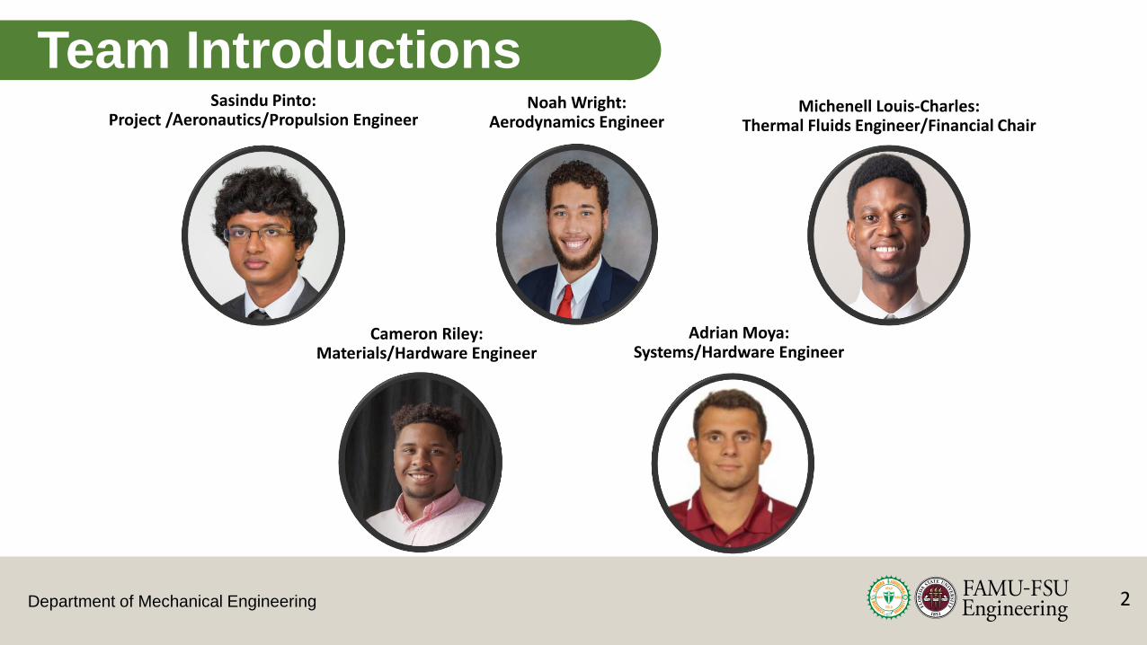
Key Definitions
Roll
Y
ZX
Department of Mechanical Engineering
Fall Semester Review
Presenter – Adrian Moya
10

Department of Mechanical Engineering
Project Background
Plane designed to be entered in SAE Aero Design Competition East
Only participating in the Design Knowledge Part due to financial constraints and heath risks
Certain elements from last year’s design will be used
Presenter: AM
11

Department of Mechanical Engineering
Key Goals
• The plane takeoff, cruise, and land while carrying a cargo load
• The plane carries a minimum of one soccer ball as the cargo load
Assumptions• Will be flown in atmospheric conditions at sea level
• Motors and electronics will be store bought and not custom-made
Presenter: AM
12

Department of Mechanical Engineering
Customer Needs
Presenter: AM
13
Takeoff within 100 ft
Fly 400ft before turning
Downwind Cruising
Final Turn for Landing
Final Approach
Land within 400 ft

Department of Mechanical Engineering
Customer Needs
A signature Innovation
Canard
Presenter: AM
14

Department of Mechanical Engineering
Functional Decomposition
Plane
Take off
Generate Lift
Generate Thrust
On Ground Stability Control
Avoid Stall
Manuvering/ Cruising
Control Pitch
Control Yaw
Control Roll
Landing
Generate Ground Friction
Increase Drag
Carrying Payload
Load/Unload Payload
Secure Payload
Presenter: AM
15

Department of Mechanical Engineering
• Generate Lift• Coefficient of Lift ~ Greater than 1
• Max Angle of Attack (AoA)• For a canard design, AoA< angle between Mean Aerodynamic Centers of the wing
• Weight• Less than 55 lbs
Targets and Metrics
Presenter: AM
16

17Department of Mechanical Engineering
Concept Generation
• Methods used• Morphological Analysis
• Biomimicry
• Competitive Benchmarking
• Crapshoot
Presenter: AM

18Department of Mechanical Engineering
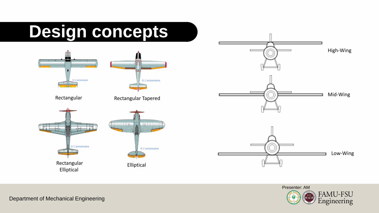
Design concepts
Rectangular Rectangular Tapered
EllipticalRectangular Elliptical
High-Wing
Low-Wing
Mid-Wing
Presenter: AM

19Department of Mechanical Engineering
Concepts ConsideredMedium and High Fidelity Concepts
1. Boomtown 2. Rutan Long EZ 3. Rutan Quickie Q2 4. Boeing 747 Dreamlifter
5. Cessna 208 Grand Caravan
6. OMAC Laser 3007. Aero SpacelinesSuper Guppy
8. Kawasaki C-2
Presenter: AM

20Department of Mechanical Engineering
Customer Needs Considered
ManeuverabilityGround Controls
Elevators
Rudder Front Wheel Control
Presenter: AM
Aileron

21Department of Mechanical Engineering
Engineering Characteristics
Lift
Drag
Thrust
Max Angle of Attack
Stall Speed
Acceleration
Control Surface Movement
Loading/Unloading Time
Weight
Deceleration
Joint Strength
Material StrengthPresenter: AM

22Department of Mechanical Engineering
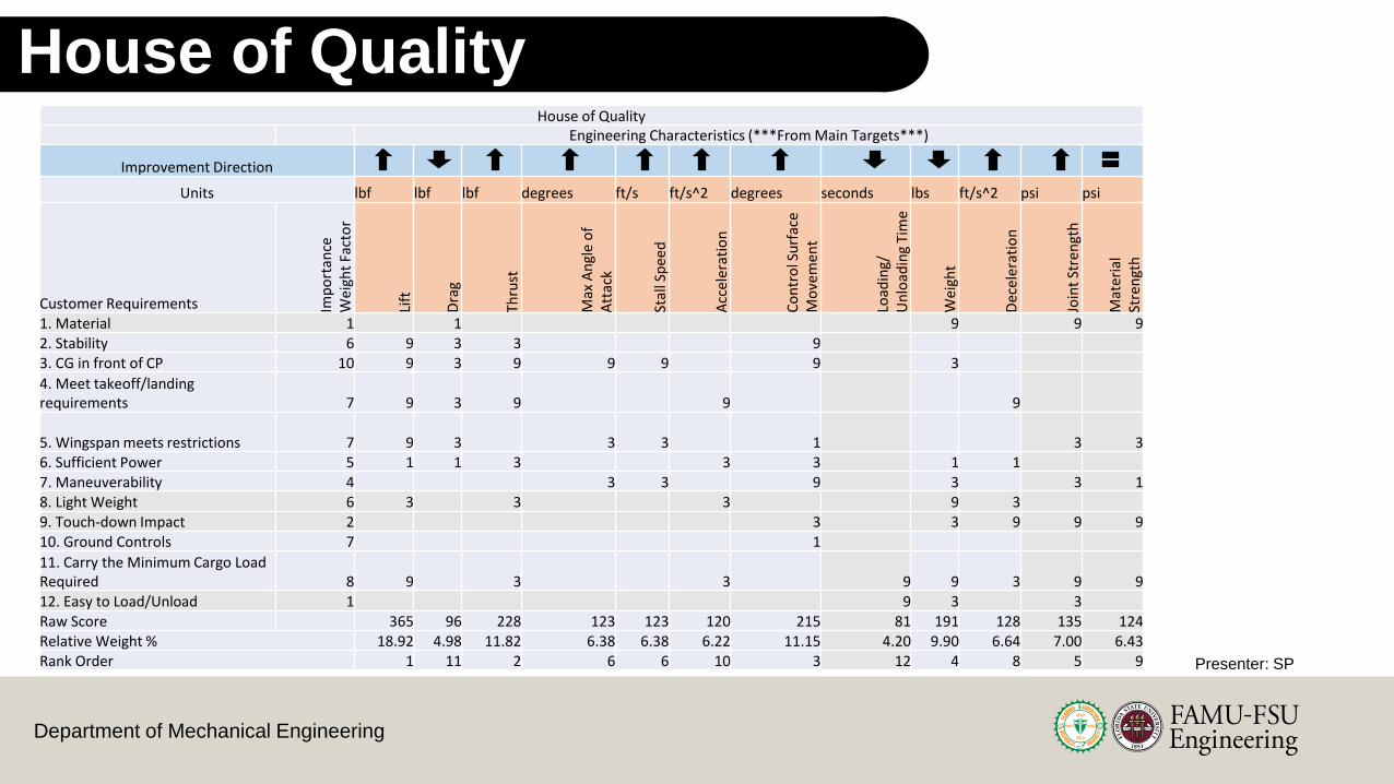
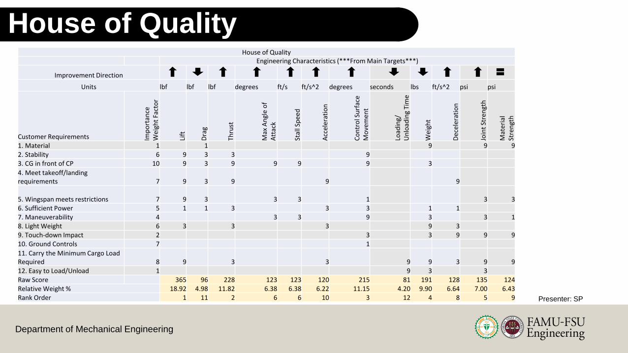
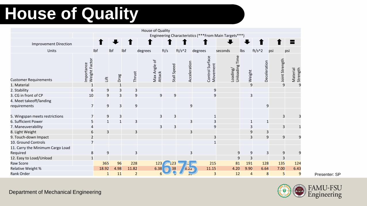
Concept Selection - House of QualityHouse of Quality
Engineering Characteristics (***From Main Targets***)
Improvement Direction
Units lbf lbf lbf degrees ft/s ft/s^2 degrees seconds lbs ft/s^2 psi psi
Customer Requirements Imp
ort
ance
W
eig
ht
Fact
or
Lift
Dra
g
Thru
st
Max
An
gle
of
Att
ack
Stal
l Sp
eed
Acc
eler
atio
n
Co
ntr
ol S
urf
ace
Mo
vem
ent
Load
ing/
U
nlo
adin
g Ti
me
Wei
ght
Dec
ele
rati
on
Join
t St
ren
gth
Mat
eri
al
Stre
ngt
h
1. Material 1 1 9 9 92. Stability 6 9 3 3 93. CG in front of CP 10 9 3 9 9 9 9 3
4. Meet takeoff/landing requirements 7 9 3 9 9 9
5. Wingspan meets restrictions 7 9 3 3 3 1 3 36. Sufficient Power 5 1 1 3 3 3 1 17. Maneuverability 4 3 3 9 3 3 18. Light Weight 6 3 3 3 9 39. Touch-down Impact 2 3 3 9 9 910. Ground Controls 7 1
11. Carry the Minimum Cargo Load Required 8 9 3 3 9 9 3 9 912. Easy to Load/Unload 1 9 3 3Raw Score 365 96 228 123 123 120 215 81 191 128 135 124Relative Weight % 18.92 4.98 11.82 6.38 6.38 6.22 11.15 4.20 9.90 6.64 7.00 6.43Rank Order 1 11 2 6 6 10 3 12 4 8 5 9 Presenter: AM

23Department of Mechanical Engineering
Pugh Chart 2
Pugh Chart 2 Concepts
High Medium
Selection Criteria Concept 2 1 3 6
Lift
Datum
- + -
Thrust S S S
Control Surface Movement + + +
Weight - - -
Joint Strength S S S
# of pluses 1 2 1
# of S's 2 2 2
# of Minuses 2 1 2
Presenter: AM

24Department of Mechanical Engineering
1. Boomtown3. Rutan Quickie Q2
6. OMAC Laser 300
Concepts Considered
for AHP
Presenter: AM

25Department of Mechanical Engineering
Criteria Comparison Matrix - AHP
Development of a Candidate set of Criteria Weights {W}
Criteria Comparison Matrix
Lift ThrustControl Surface Movement Weight Joint Strength
Lift 1.00 0.33 3.00 9.00 9.00
Thrust 3.00 1.00 3.00 9.00 9.00
Control Surface Movement 0.33 0.33 1.00 5.00 3.00
Weight 0.11 0.11 0.20 1.00 0.11
Joint Strength 0.11 0.11 0.33 9.00 1.00
Sum 4.56 1.89 7.53 33.00 22.11
λ Average Consistency
CI Consistency Index
CR Consistency Ratio
6.053 0.027 0.051
All Criteria Comparison Plots
Presenter: AM

26Department of Mechanical Engineering
Lift Comparison for Concepts - AHP
Concept 3: Rutan Quickie Q2
Canard + Main Wing
Lift
Concept 6: OMAC 300 Laser Plane Concept 1: BoomtownPresenter: AM

27Department of Mechanical Engineering
Final Rating & Alternative Values - AHPFinal Rating Matrix
Selection Criteria Concept 1 Concept 2 Concept 6
Lift 0.243 0.669 0.088
Thrust 0.333 0.333 0.333
Control Surface Movement 0.236 0.110 0.654
Weight 0.260 0.633 0.106
Joint Strength 0.333 0.333 0.333
ConceptAlternative Value
Concept 1 0.292
Concept 3 0.411
Concept 6 0.297
Presenter: AM

28Department of Mechanical Engineering
Concept Comparison- AHP
0.000
0.050
0.100
0.150
0.200
0.250
0.300
0.350
0.400
0.450
Concept 1 Concept 3 Concept 6
Alternative Value
Presenter: AM

29Department of Mechanical Engineering
Chosen Design
Dual Wing Layout
Single Propeller
Elevators
Ailerons
Rudder
Presenter: AM

30Department of Mechanical Engineering
Sasindu Pinto
Thrust Test and Landing Gear Configuration
Department of Mechanical Engineering
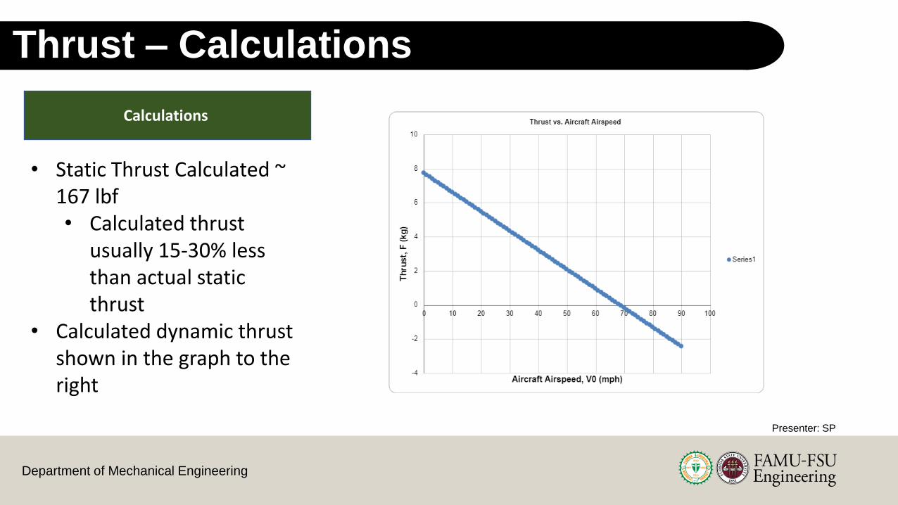
Thrust – Calculations
Calculations
• Static Thrust Calculated ~ 167 lbf• Calculated thrust
usually 15-30% less than actual static thrust
• Calculated dynamic thrust shown in the graph to the right
Presenter: SP

Department of Mechanical Engineering
Thrust – Experimental Test
Thrust Test Setup
Battery
Remote Control
Receiver Power Limiter
Electronic Speed Controller
Propellor
MotorFulcrumRed-Arming Plug
Experimental Thrust ~ 222 lbf
Presenter: SP

33Department of Mechanical Engineering
Landing Gear Positioning
CG
Back Landing Gear Position: 2.5 in Back Landing Gear Position: 2.5 in
Presenter: SP

34Department of Mechanical Engineering
Weight Distribution
CG
Weight
20%80%
Weight Distribution 1:240% for Each Landing Gear
Presenter: SP

35Department of Mechanical Engineering
Dimensions, Initial CAD Design & CFD
Presenter – Adrian Moya
35
36Department of Mechanical Engineering
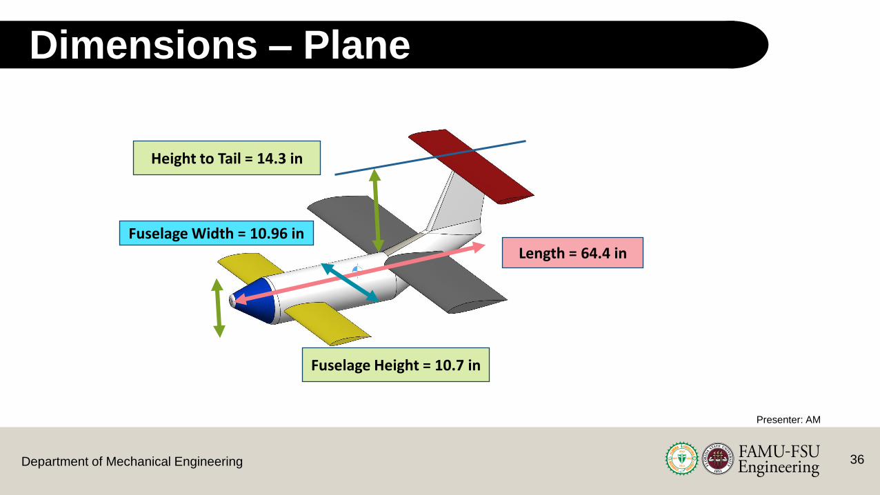
Dimensions – Plane
Presenter: AM
Length = 64.4 in
Height to Tail = 14.3 in
Fuselage Height = 10.7 in
Fuselage Width = 10.96 in
37Department of Mechanical Engineering
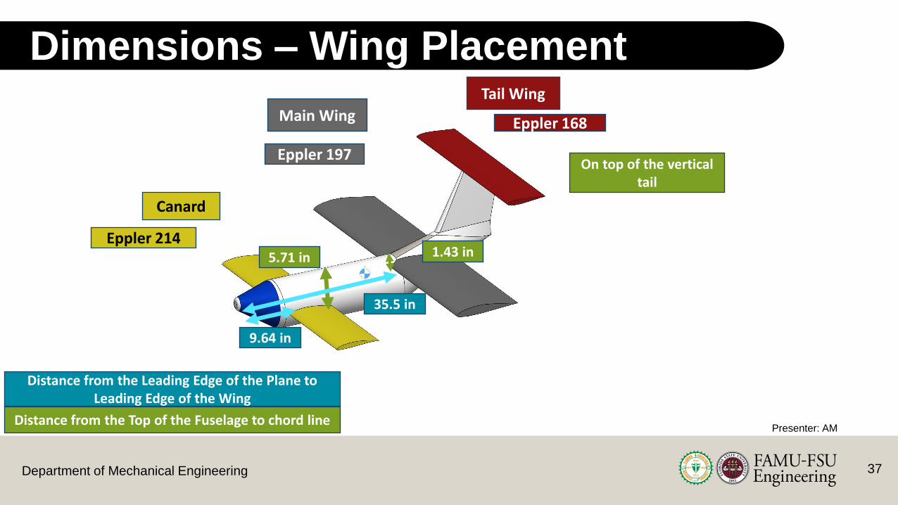
Dimensions – Wing Placement
Presenter: AM
Canard
Main Wing
Tail Wing
9.64 in
5.71 in 1.43 in
35.5 in
On top of the vertical tail
Distance from the Leading Edge of the Plane to Leading Edge of the Wing
Distance from the Top of the Fuselage to chord line
Eppler 214
Eppler 197
Eppler 168

38Department of Mechanical Engineering
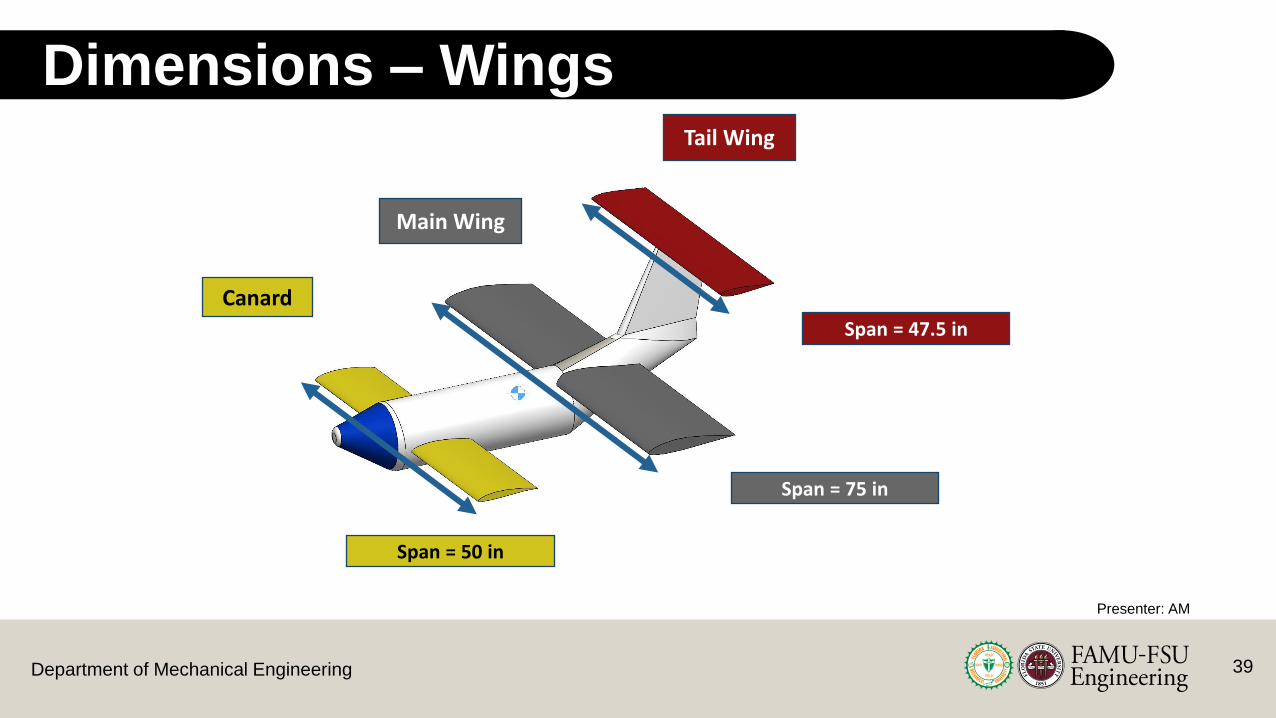
Dimensions – Wings
Presenter: AM
Canard
Main Wing
Tail Wing
Chord Length = 12 in
Chord Length = 15 in
Chord Length = 9 in
39Department of Mechanical Engineering
Dimensions – Wings
Presenter: AM
Canard
Main Wing
Tail Wing
Span = 50 in
Span = 75 in
Span = 47.5 in
40Department of Mechanical Engineering
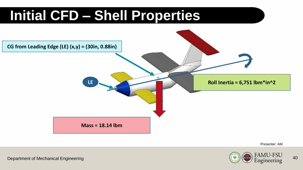
Initial CFD – Shell Properties
Presenter: AM
Mass = 18.14 lbm
Roll Inertia = 6,751 lbm*in^2
CG from Leading Edge (LE) (x,y) = (30in, 0.88in)
LE

41Department of Mechanical Engineering
Initial CFD – With Propeller & Landing Gear
Presenter: AM
Vorticies below the fuselage

Department of Mechanical Engineering
CFD – Wing Vorticity
Canard Main Wing Tail Wing
Presenter: AM
More vorticity due to concave shape on the bottom
Relatively less vorticity as the shapes are more symmetric

Department of Mechanical Engineering
CFD – Wing Turbulence
Presenter: AM
Negligible wake effects between wings

Department of Mechanical Engineering
CFD – Fuselage Turbulence
Presenter: AM
Turbulence Effects Negligible
Department of Mechanical Engineering
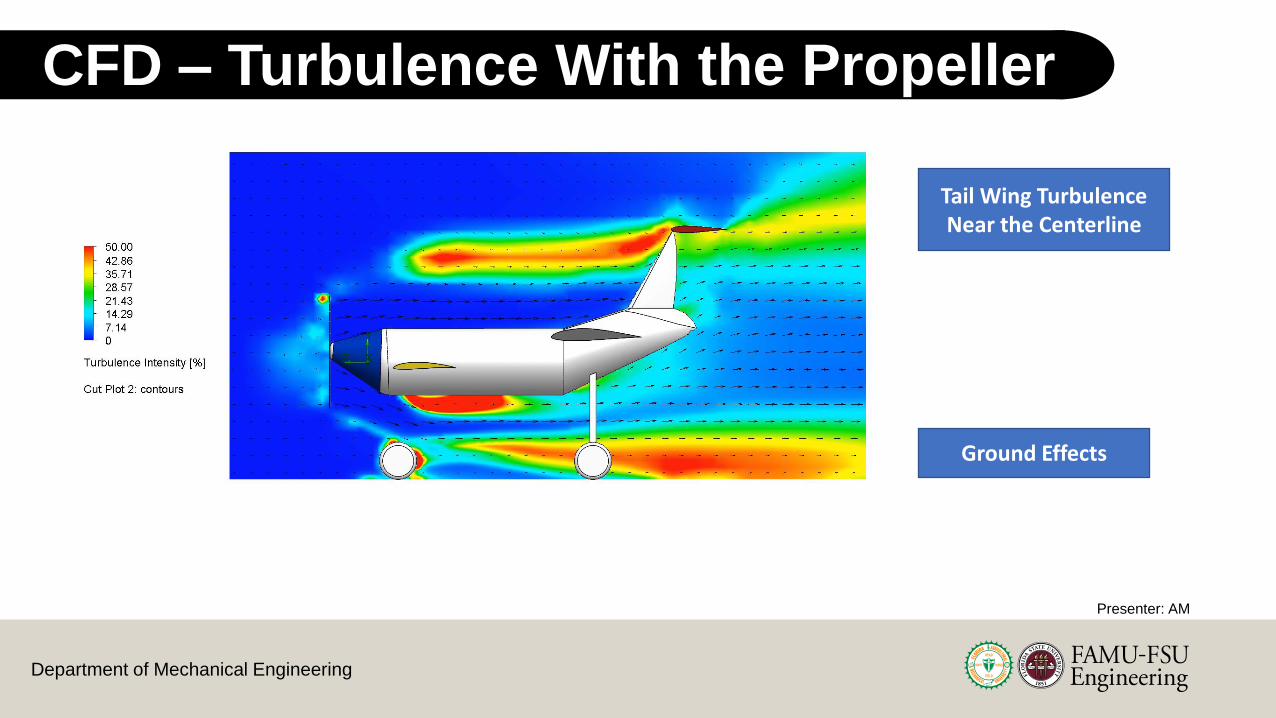
CFD – Turbulence With the Propeller
Presenter: AM
Tail Wing Turbulence Near the Centerline
Ground Effects

Department of Mechanical Engineering 46
Xfoil Analysis
Canard
Main
Tail
Canard Stall
Main Wing Stall
Canard
Main
Tail
Constant Moment Region
Presenter: AM
Department of Mechanical Engineering 47
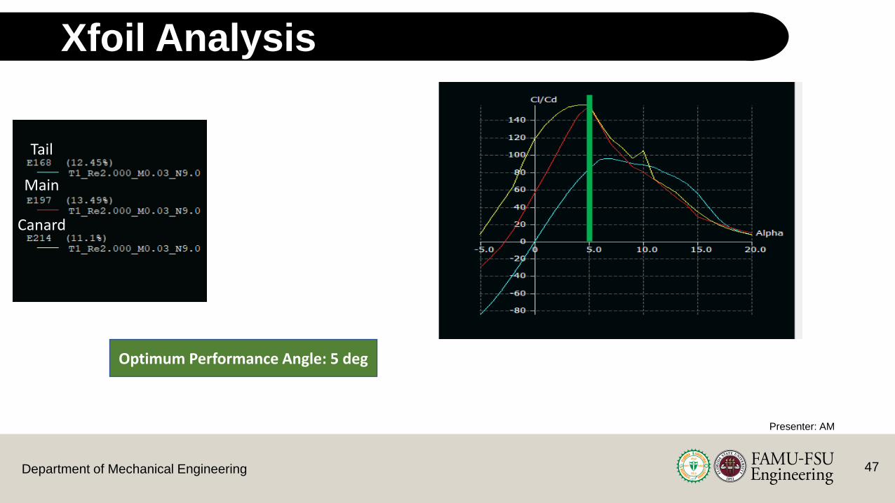
Xfoil Analysis
Optimum Performance Angle: 5 deg
Canard
Main
Tail
Presenter: AM

Department of Mechanical Engineering
Presenter – Sasindu Pinto
Stability Calculations
Department of Mechanical Engineering
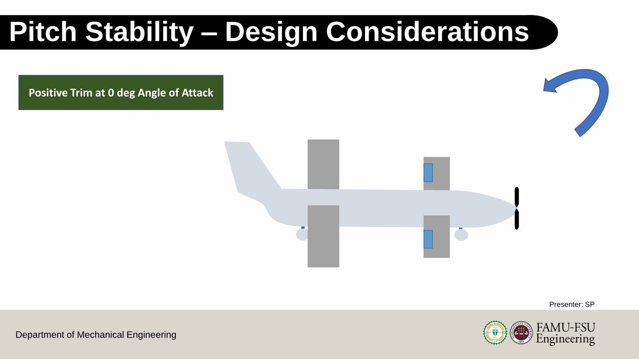
Pitch Stability – Design Considerations
Positive Trim at 0 deg Angle of Attack
Presenter: SP
Department of Mechanical Engineering
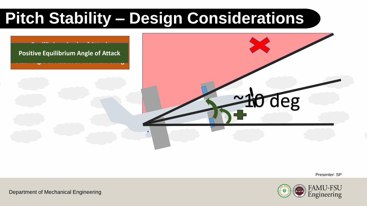
Pitch Stability – Design Considerations
Equilibrium Angle of Attack <
Stall Angle of Attack of the Main WingPositive Equilibrium Angle of Attack
~10 deg
Presenter: SP
Department of Mechanical Engineering
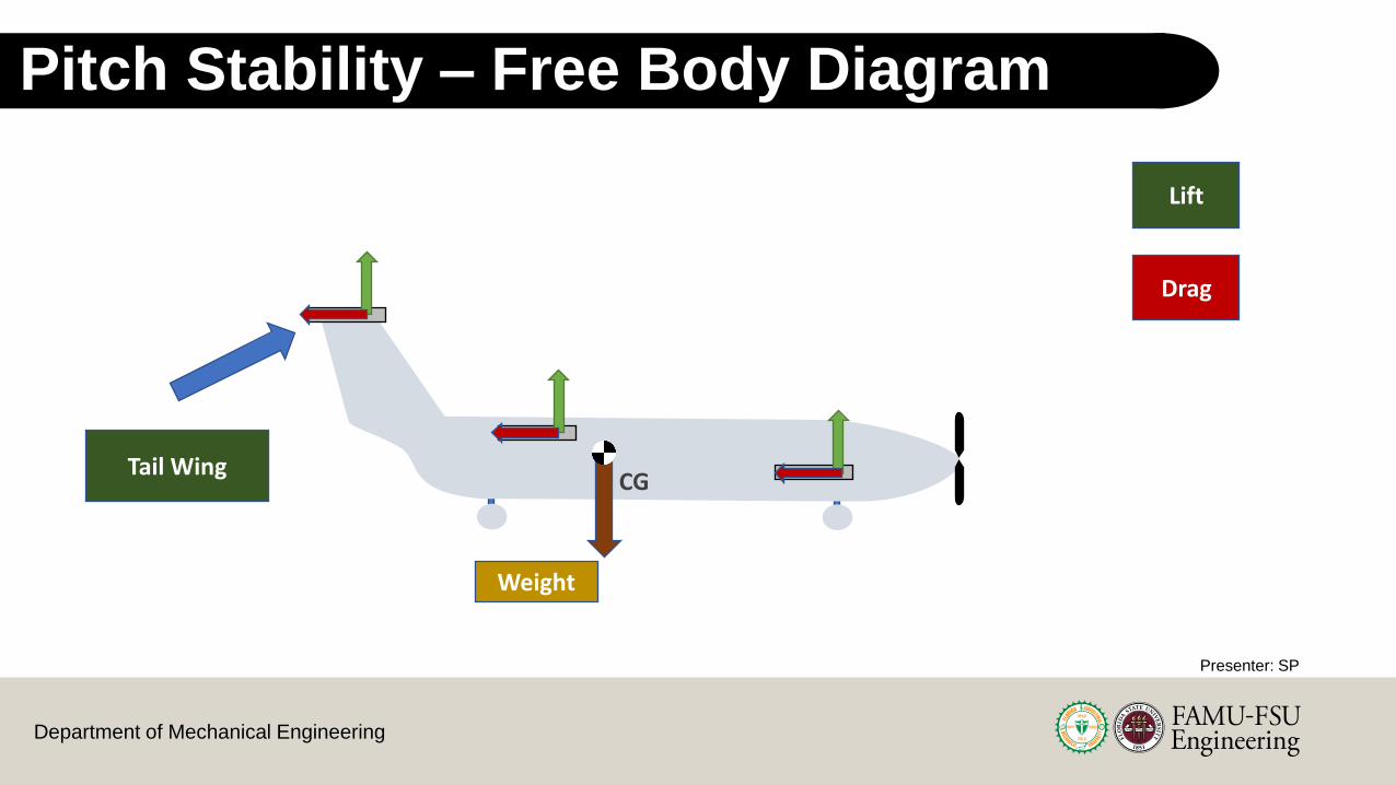
Pitch Stability – Free Body Diagram Considerations
Lift
Drag
CGTail Wing
Weight
Presenter: SP

Department of Mechanical Engineering
Pitch Stability – Initial Stability Plot
Positive Trim
Presenter: SP
0 deg

Department of Mechanical Engineering
Pitch Stability – Initial Stability Plot
Negative Equilibrium Angle of Attack
Presenter: SP
0 deg
Department of Mechanical Engineering
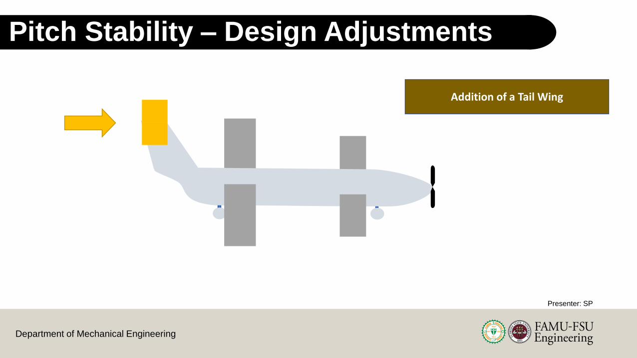
Pitch Stability – Design Adjustments
Addition of a Tail Wing
Presenter: SP
Department of Mechanical Engineering
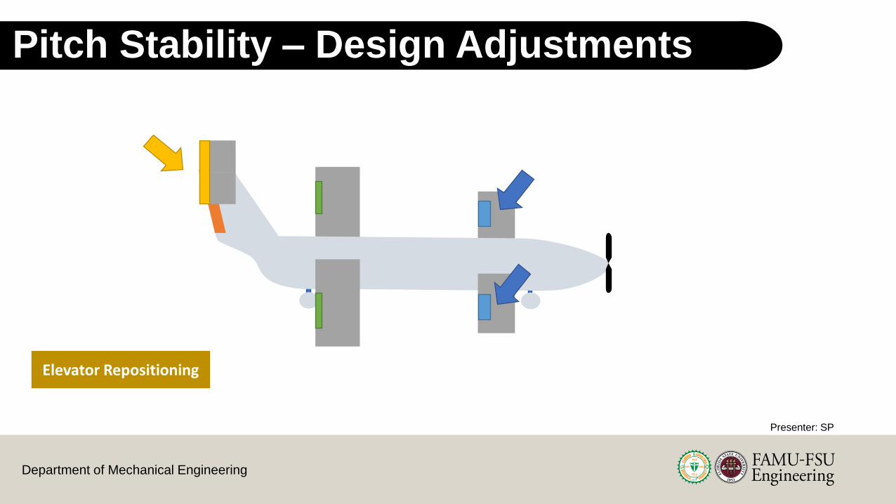
Pitch Stability – Design Adjustments
Elevator Repositioning
Presenter: SP

Department of Mechanical Engineering
Pitch Stability – Final Stability Plot
Positive Trim
Positive Equilibrium Angle of Attack
Presenter: SP
0 deg

Department of Mechanical Engineering
Pitch Stability – Outcome
~3.125 deg
Equilibrium Angle of Attack
Pitch Stability – Outcomes
Presenter: SP
Department of Mechanical Engineering
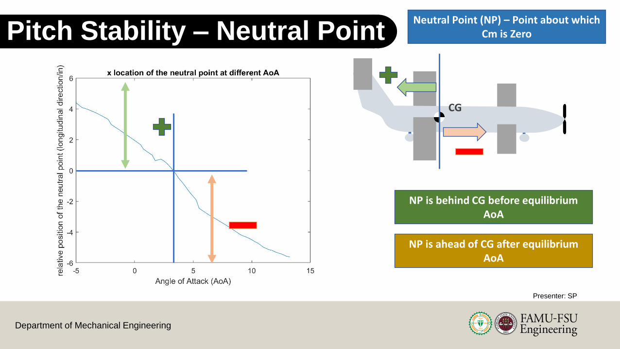
Pitch Stability – OutcomePitch Stability – Neutral Point
NP is behind CG before equilibrium AoA
NP is ahead of CG after equilibrium AoA
CG
Presenter: SP
Neutral Point (NP) – Point about which Cm is Zero

Department of Mechanical Engineering
Pitch Stability – Outcomes - Elevator
Presenter: SP

Department of Mechanical Engineering
Pitch Stability – Outcomes - Elevator
Elevator Span – 47.5 in
Elevator Chord Length – 3.6 in
Deflection angle – 30 deg
Elevator Span – 47.5 in
Deflection angle – 30 deg
Presenter: SP
61Department of Mechanical Engineering
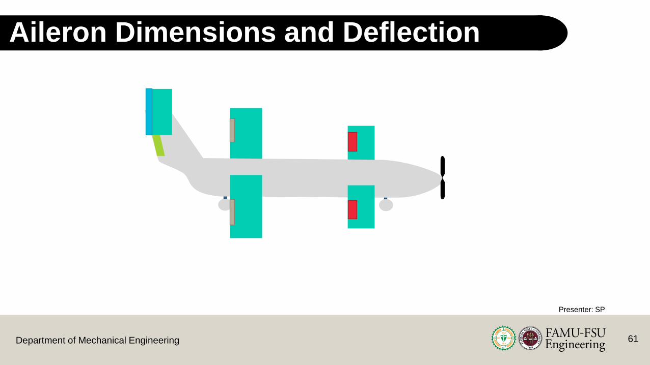
Aileron Dimensions and Deflection
Presenter: SP

62Department of Mechanical Engineering
Aileron Dimensions
Aileron Chord Length – 3.75 inAileron Span – 12.25 in
Distance to Fuselage – 21 in
Presenter: SP
63Department of Mechanical Engineering
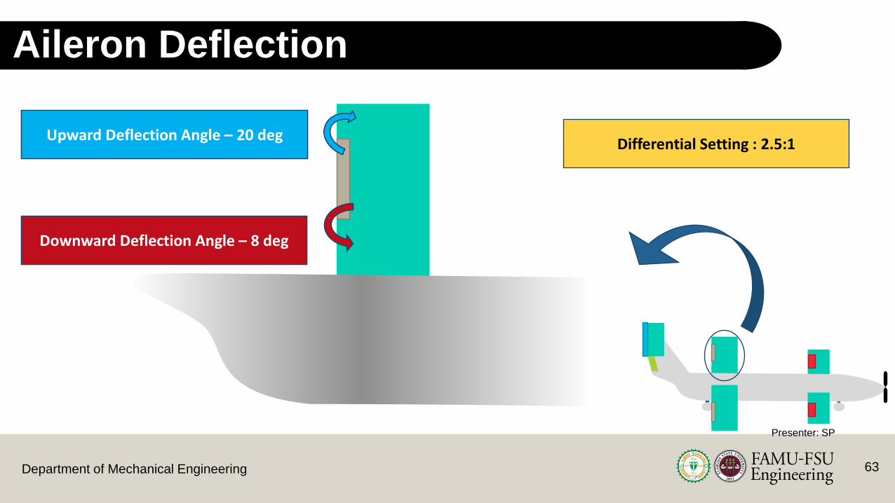
Aileron Deflection
Upward Deflection Angle – 20 deg
Downward Deflection Angle – 8 deg
Differential Setting : 2.5:1Upward Deflection Angle – 20 deg
Downward Deflection Angle – 8 deg
Presenter: SP

64Department of Mechanical Engineering
Rudder Dimensions and Deflection
Presenter: SP
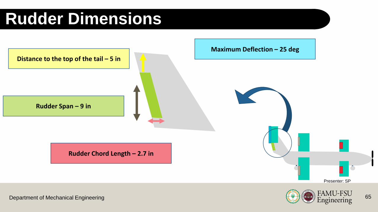
65Department of Mechanical Engineering
Rudder Dimensions
Rudder Chord Length – 2.7 in
Rudder Span – 9 in
Distance to the top of the tail – 5 in
Maximum Deflection – 25 deg
Presenter: SP

66Department of Mechanical Engineering
Roll Stability – Design Considerations
Lright
Lleft
Right Roll
Lright<<Lleft
Upward Deflection Angle – 20 degDownward Deflection Angle – 8 deg
Presenter: SP

67Department of Mechanical Engineering
Roll Stability – Operation
Roll Rate: 3.3 deg/s
~15.78 deg
Stable Roll Angle
Presenter: SP
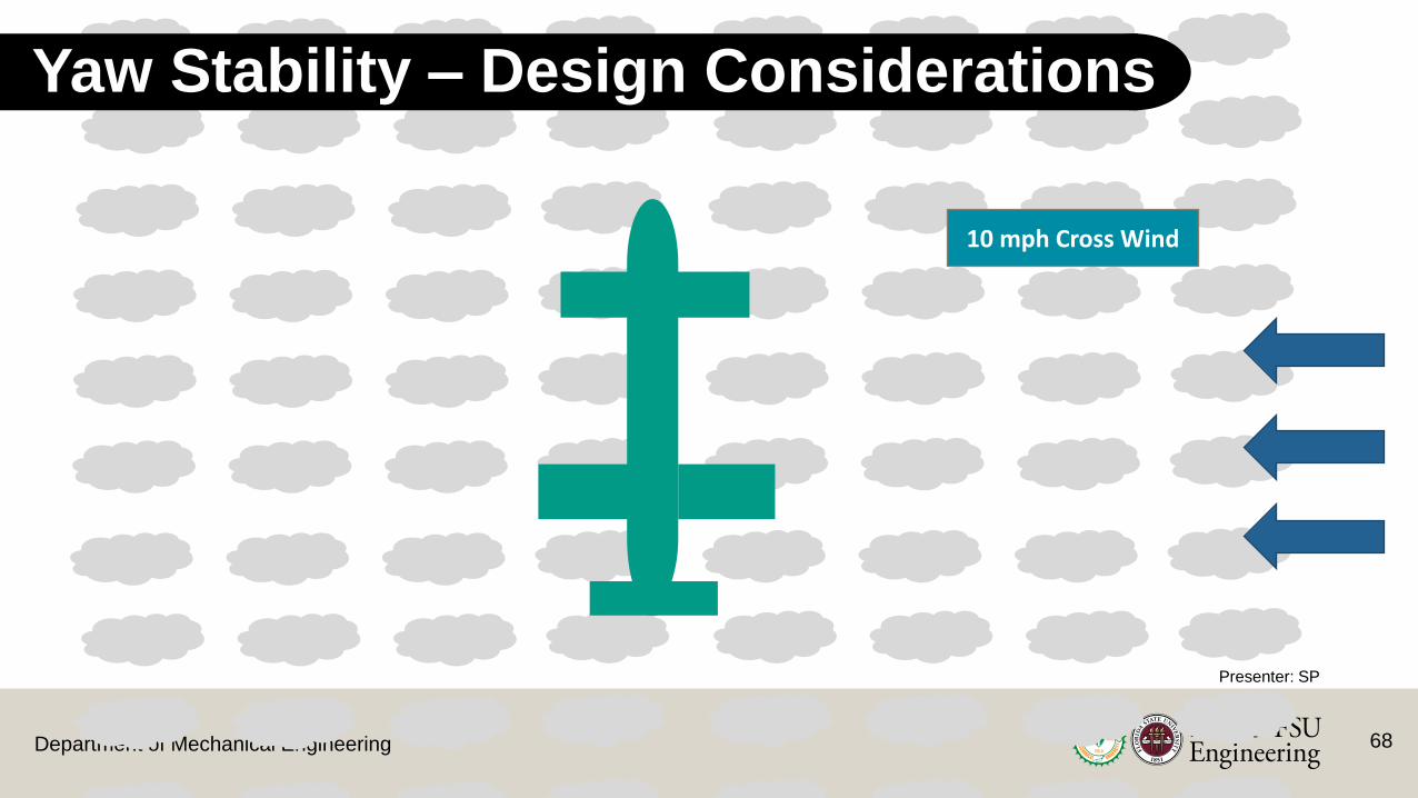
68Department of Mechanical Engineering
Yaw Stability – Design Considerations
10 mph Cross Wind
Presenter: SP

69Department of Mechanical Engineering
10 mph Cross Wind
Yaw Stability – Operation
10 deg rudder rotation
Presenter: SP

70Department of Mechanical Engineering
Yaw Stability – Operation
10 mph Cross Wind
~50 deg
Landing Angle: 50 deg
Presenter: SP

71Department of Mechanical Engineering
Control Surface Servos
KST X10 Wing ServoOld Vs. New
Weight (oz.)1.59 | 1.0
Operating Voltage4.8V- 6V | 6V to 8.4V
Max Torque (oz-in)83 | 149
Price$20 | $45
Hitech HS-485HB
• A contact at the RC club strongly recommended not using the servo brand currently owned by the COE and suggested more reliable options
Presenter: SP

Department of Mechanical Engineering 72
Current Work – CAD Assistance
Main Wing
Tail Wing – Vertical Section
Presenter: SP

Department of Mechanical Engineering 73
Current Work – Design Report
• Required for the design knowledge event• Minimum page amount – 30 pages
• Includes the complete design process and the manufacturing event
• Was submitted on 01/18/2021
Presenter: SP
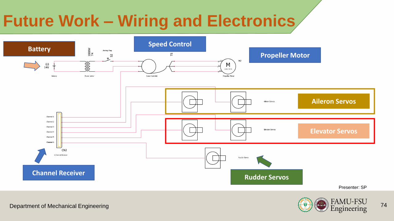
Department of Mechanical Engineering 74
Future Work – Wiring and Electronics
Presenter: SP
Aileron Servos
Elevator Servos
Rudder Servos
Propeller Motor
Speed Control
Channel Receiver
Battery

Department of Mechanical Engineering
Project Timeline – Spring
Presenter: SP
75
CFD of the Plane
Final Adjustments to Design
Wind Tunnel Testing
Complete CAD for The Entire Plane
Assembly and Electrical Setup
JAN FEB MAR
Test Flight 1
Flight Review
Finalize Stability
Test Flight 2
APR

Department of Mechanical Engineering
References
Aircraft Design: A Systems Engineering Approach. M.H. Sadraey. 2013. 1st Edition. John Wiley Publications.
Basics of RC Model Aircraft Design: Practical Techniques for building better models. A. Lennon. 1999. Air Age Inc.
Fundamentals of Aerodynamics. John D. Anderson Jr. 2011. 5th Edition. McGraw Hill Publications.
Fuselage Shapes. Academic. N.d. https://enacademic.com/dic.nsf/enwiki/109692
SAE Aero Design Competition 2021 Rule Book. Available on: https://public.3.basecamp.com/p/38Lpy4uyTLpNkwTZbtwjgtBZ
Tail Types. What-When-How. N.d. http://what-when-how.com/flight/tail-designs/
Presenter: AM
76
Department of Mechanical Engineering 77
Trust and LG CAD and CFD Stability
Information
Noah WrightSasindu Pinto Michenell Louis-
CharlesCameron Riley Adrian Moya
Backup Slides – Part 2

Department of Mechanical Engineering
Backup Slides
78

Department of Mechanical Engineering
Markets and Stakeholders
Primary
SAE Aero Design Competition
Advisors
Sponsors
Secondary
Professionals in the Aviation field
Aviation Companies
RC Hobbyists
Scholars that reference this project
Dr. McConomy and Dr.
Shih
FAMU-FSU College
of Engineering
SAE Design Competition
RC Pilots
Markets Stakeholders
Presenter: CR
79
Department of Mechanical Engineering
Design concepts
Rectangular Rectangular Tapered
EllipticalRectangular Elliptical
High-Wing
Low-Wing
Mid-Wing
Presenter: AM

Department of Mechanical Engineering
Design Concepts
Fuselage Layouts
Presenter: AM

Department of Mechanical Engineering
Morphological AnalysisMorphological Analysis
Wing Layout Wing TypeWing Position
Control Surfaces
Fuselage Tail
Main-TailMain - Forward Swept Tail- Symmetric (x-29)
High Wing Aileron BulletBoom-Mounted Inverted V
Trapezoidal Delta Wing Mid Wing Flaps Flying Boat H-Tail
Canard-MainMain - Elliptical Tail -Symmetric
Low Wing Elevators Double Boom Twin-Tail
Main - Trapezoidal Tail - Symmetric
Tapered
Triple-Tail
Y-Tail
82

Department of Mechanical Engineering
Competitive Benchmarking
Rutan Long E-Z:Small composite plane with canards & tip sails
Cessna 208 Grand Caravan:Typical bush plane with extra cargo space
Kawasaki C-2:Japanese military cargo plane
Presenter: AM

Department of Mechanical Engineering
Binary Pairwise ComparisonBinary Pairwise Comparison
1 2 3 4 5 6 7 8 9 10 11 12Total1. Material - 0 0 0 0 0 0 1 0 0 0 0 12. Stability 1 - 0 0 0 1 1 1 1 0 0 1 63. CG in front of CP 1 1 - 1 1 1 1 1 1 1 1 1 10
4. Meet takeoff/landing requirements 1 1 0 - 1 1 1 0 1 0 0 1 7
5. Wingspan meets restrictions 1 1 0 0 - 1 1 1 1 0 0 1 76. Sufficient Power 1 0 0 0 0 - 0 0 1 1 1 1 57. Maneuverability 1 0 0 0 0 1 - 0 1 0 0 1 48. Light Weight 0 0 0 1 0 1 1 - 1 1 0 1 69. Touch-down Impact 1 0 0 0 0 0 0 0 - 0 0 1 210. Ground Controls 1 1 0 1 1 0 1 0 1 - 1 1 7
11. Carry the Minimum Cargo Load Required 1 1 0 1 1 0 1 1 1 0 - 1 8
12. Easy to Load/Unload 1 0 0 0 0 0 0 0 0 0 0 - 1Total 10 5 0 4 4 6 7 5 9 4 3 10 - Presenter: AM

Department of Mechanical Engineering
Binary Pairwise ComparisonBinary Pairwise Comparison
1 2 3 4 5 6 7 8 9 10 11 12Total1. Material - 0 0 0 0 0 0 1 0 0 0 0 12. Stability 1 - 0 0 0 1 1 1 1 0 0 1 63. CG in front of CP 1 1 - 1 1 1 1 1 1 1 1 1 10
4. Meet takeoff/landing requirements 1 1 0 - 1 1 1 0 1 0 0 1 7
5. Wingspan meets restrictions 1 1 0 0 - 1 1 1 1 0 0 1 76. Sufficient Power 1 0 0 0 0 - 0 0 1 1 1 1 57. Maneuverability 1 0 0 0 0 1 - 0 1 0 0 1 48. Light Weight 0 0 0 1 0 1 1 - 1 1 0 1 69. Touch-down Impact 1 0 0 0 0 0 0 0 - 0 0 1 210. Ground Controls 1 1 0 1 1 0 1 0 1 - 1 1 7
11. Carry the Minimum Cargo Load Required 1 1 0 1 1 0 1 1 1 0 - 1 8
12. Easy to Load/Unload 1 0 0 0 0 0 0 0 0 0 0 - 1Total 10 5 0 4 4 6 7 5 9 4 3 10 - Presenter: AMPresenter: AM

Department of Mechanical Engineering
HOQ
86

Department of Mechanical Engineering
House of QualityEngineering Characteristics (***From Main Targets***)
Improvement Direction
Units lbf lbf lbf degrees ft/s ft/s^2 degrees seconds lbs ft/s^2 psi psi
Customer Requirements Imp
ort
ance
W
eig
ht
Fact
or
Lift
Dra
g
Thru
st
Max
An
gle
of
Att
ack
Stal
l Sp
eed
Acc
eler
atio
n
Co
ntr
ol S
urf
ace
Mo
vem
ent
Load
ing/
U
nlo
adin
g Ti
me
Wei
ght
Dec
ele
rati
on
Join
t St
ren
gth
Mat
eri
al
Stre
ngt
h
1. Material 1 1 9 9 92. Stability 6 9 3 3 93. CG in front of CP 10 9 3 9 9 9 9 3
4. Meet takeoff/landing requirements 7 9 3 9 9 9
5. Wingspan meets restrictions 7 9 3 3 3 1 3 36. Sufficient Power 5 1 1 3 3 3 1 17. Maneuverability 4 3 3 9 3 3 18. Light Weight 6 3 3 3 9 39. Touch-down Impact 2 3 3 9 9 910. Ground Controls 7 1
11. Carry the Minimum Cargo Load Required 8 9 3 3 9 9 3 9 912. Easy to Load/Unload 1 9 3 3Raw Score 365 96 228 123 123 120 215 81 191 128 135 124Relative Weight % 18.92 4.98 11.82 6.38 6.38 6.22 11.15 4.20 9.90 6.64 7.00 6.43Rank Order 1 11 2 6 6 10 3 12 4 8 5 9 Presenter: SP
House of Quality

Department of Mechanical Engineering
House of QualityHouse of Quality
Engineering Characteristics (***From Main Targets***)
Improvement Direction
Units lbf lbf lbf degrees ft/s ft/s^2 degrees seconds lbs ft/s^2 psi psi
Customer Requirements Imp
ort
ance
W
eig
ht
Fact
or
Lift
Dra
g
Thru
st
Max
An
gle
of
Att
ack
Stal
l Sp
eed
Acc
eler
atio
n
Co
ntr
ol S
urf
ace
Mo
vem
ent
Load
ing/
U
nlo
adin
g Ti
me
Wei
ght
Dec
ele
rati
on
Join
t St
ren
gth
Mat
eri
al
Stre
ngt
h
1. Material 1 1 9 9 92. Stability 6 9 3 3 93. CG in front of CP 10 9 3 9 9 9 9 3
4. Meet takeoff/landing requirements 7 9 3 9 9 9
5. Wingspan meets restrictions 7 9 3 3 3 1 3 36. Sufficient Power 5 1 1 3 3 3 1 17. Maneuverability 4 3 3 9 3 3 18. Light Weight 6 3 3 3 9 39. Touch-down Impact 2 3 3 9 9 910. Ground Controls 7 1
11. Carry the Minimum Cargo Load Required 8 9 3 3 9 9 3 9 912. Easy to Load/Unload 1 9 3 3Raw Score 365 96 228 123 123 120 215 81 191 128 135 124Relative Weight % 18.92 4.98 11.82 6.38 6.38 6.22 11.15 4.20 9.90 6.64 7.00 6.43Rank Order 1 11 2 6 6 10 3 12 4 8 5 9 Presenter: SP
Department of Mechanical Engineering
Pugh Charts

Department of Mechanical Engineering
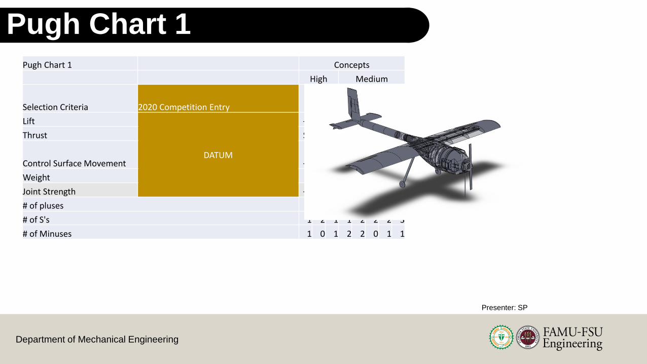
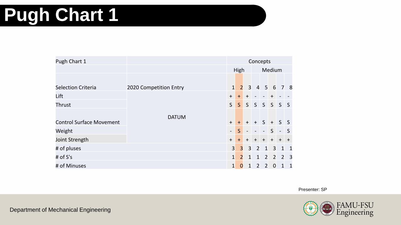
Pugh Chart 1
Pugh Chart 1 Concepts
High Medium
Selection Criteria 2020 Competition Entry 1 2 3 4 5 6 7 8
Lift
DATUM
+ + + - - + - -
Thrust S S S S S S S S
Control Surface Movement + + + + S + S S
Weight - S - - - S - S
Joint Strength + + + + + + + +
# of pluses 3 3 3 2 1 3 1 1
# of S's 1 2 1 1 2 2 2 3
# of Minuses 1 0 1 2 2 0 1 1
Presenter: SP
Department of Mechanical Engineering
Pugh Chart 1Pugh Chart 1 Concepts
High Medium
Selection Criteria 2020 Competition Entry 1 2 3 4 5 6 7 8
Lift
DATUM
+ + + - - + - -
Thrust S S S S S S S S
Control Surface Movement + + + + S + S S
Weight - S - - - S - S
Joint Strength + + + + + + + +
# of pluses 3 3 3 2 1 3 1 1
# of S's 1 2 1 1 2 2 2 3
# of Minuses 1 0 1 2 2 0 1 1
Presenter: SP
Department of Mechanical Engineering
Pugh Chart 1
Pugh Chart 1 Concepts
High Medium
Selection Criteria 2020 Competition Entry 1 2 3 4 5 6 7 8
Lift
DATUM
+ + + - - + - -
Thrust S S S S S S S S
Control Surface Movement + + + + S + S S
Weight - S - - - S - S
Joint Strength + + + + + + + +
# of pluses 3 3 3 2 1 3 1 1
# of S's 1 2 1 1 2 2 2 3
# of Minuses 1 0 1 2 2 0 1 1
Presenter: SP
Department of Mechanical Engineering
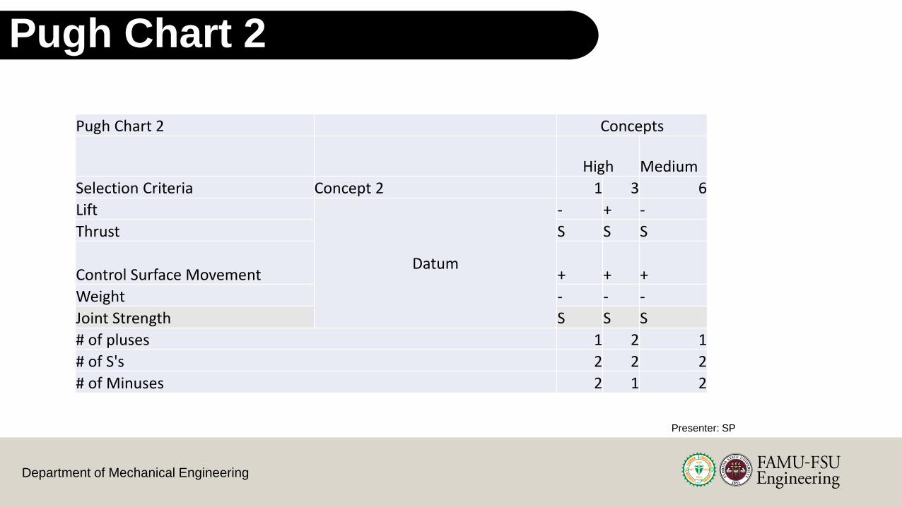
Pugh Chart 2
Pugh Chart 2 Concepts
High Medium
Selection Criteria Concept 2 1 3 6
Lift
Datum
- + -
Thrust S S S
Control Surface Movement + + +
Weight - - -
Joint Strength S S S
# of pluses 1 2 1
# of S's 2 2 2
# of Minuses 2 1 2
Presenter: SP

Department of Mechanical Engineering
Pugh Chart 2
Pugh Chart 2 Concepts
High Medium
Selection Criteria Concept 2 1 3 6
Lift
Datum
- + -
Thrust S S S
Control Surface Movement + + +
Weight - - -
Joint Strength S S S
# of pluses 1 2 1
# of S's 2 2 2
# of Minuses 2 1 2
Presenter: SP
Department of Mechanical Engineering
AHP Criteria Comparison
99

Department of Mechanical Engineering
Criteria Comparison - AHPLift vs Thrust
Lift
Thrust
Presenter: SP

Department of Mechanical Engineering
Criteria Comparison - AHPLift vs Control
Surface
Elevators/AileronsRudder
Lift
Presenter: SP

Department of Mechanical Engineering
Criteria Comparison - AHPThrust vs Control
Surface
Elevators/AileronsRudderThrust
Criteria Comparison - AHP
Presenter: SP

Department of Mechanical Engineering
1. Boomtown 3. Rutan Quickie Q2
6. OMAC Laser 300
Concepts Considered
for AHP
Presenter: SP

Department of Mechanical Engineering
Lift Comparison for Concepts - AHP
Lift
Concept 1: Boomtown
Just the main wing
Presenter: SP

Department of Mechanical Engineering
Lift Comparison for Concepts - AHP
Concept 3: Rutan Quickie Q2
Canard + Main Wing
Lift
Presenter: SP

Department of Mechanical Engineering
Lift Comparison for Concepts - AHP
Concept 6: OMAC 300 Laser Plane
Lower Wingspan + Delta Restriction
Tip Sails
Lift
Presenter: SP
Department of Mechanical Engineering
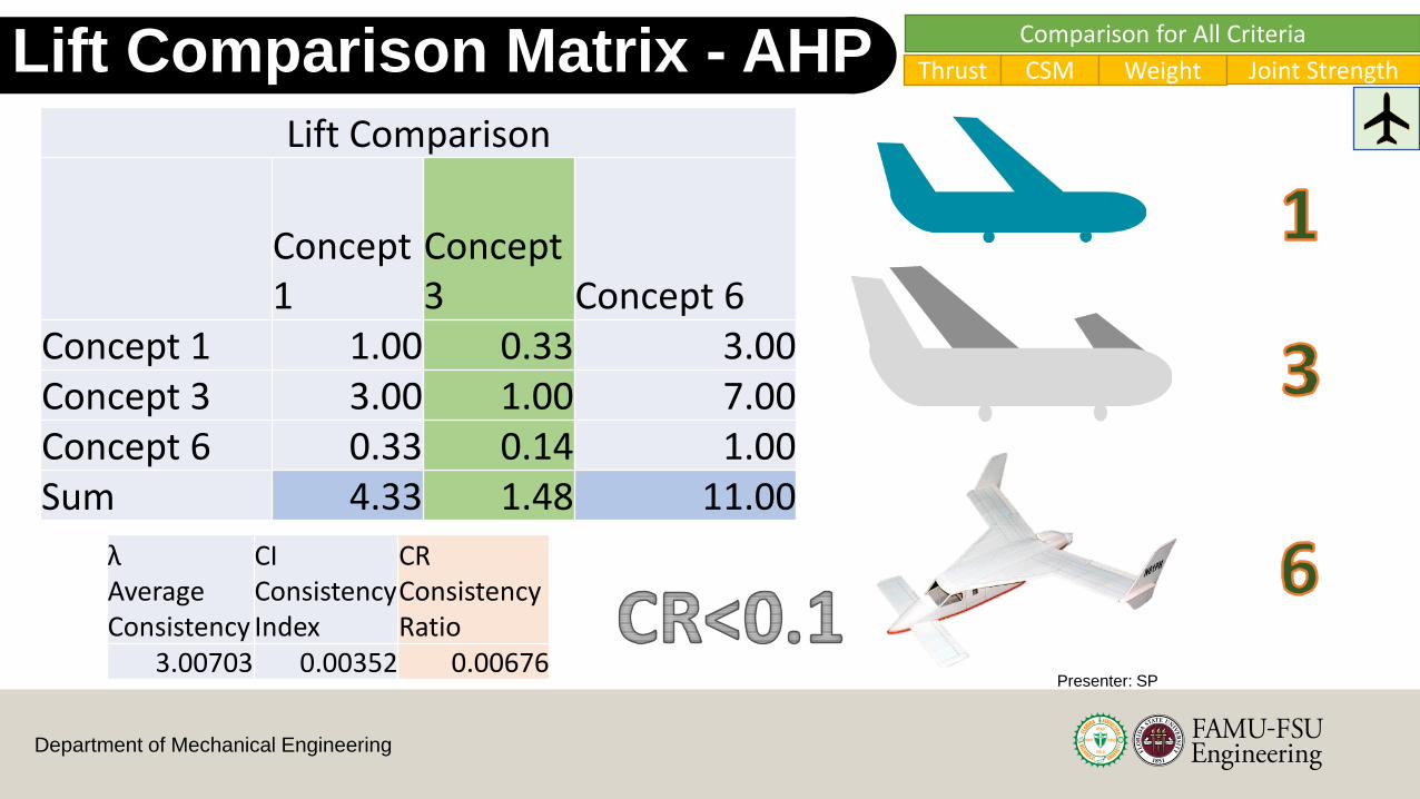
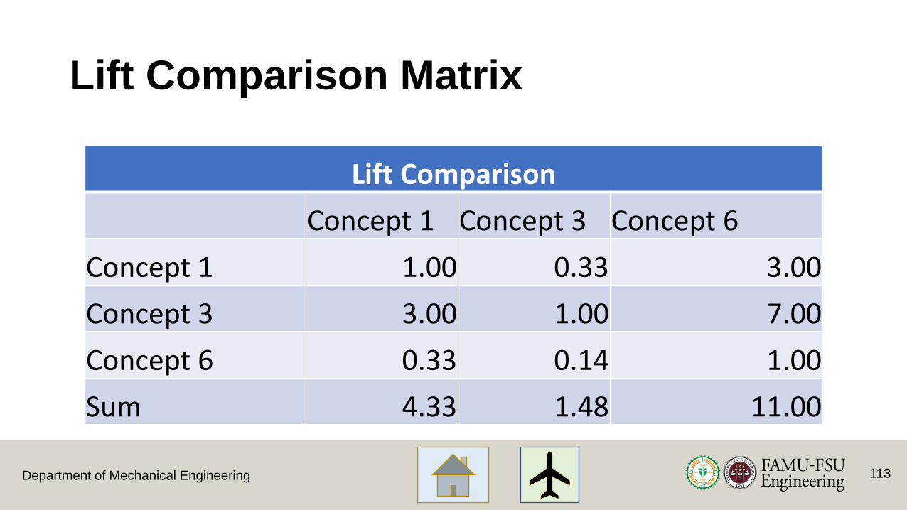
Lift Comparison Matrix - AHP
Lift Comparison
Concept 1
Concept 3 Concept 6
Concept 1 1.00 0.33 3.00Concept 3 3.00 1.00 7.00Concept 6 0.33 0.14 1.00Sum 4.33 1.48 11.00
λ Average Consistency
CI Consistency Index
CR Consistency Ratio
3.00703 0.00352 0.00676Presenter: SP
Comparison for All Criteria
Thrust CSM Weight Joint Strength

Department of Mechanical Engineering
Concept Comparison- AHP
0.000
0.050
0.100
0.150
0.200
0.250
0.300
0.350
0.400
0.450
Concept 1 Concept 3 Concept 6
Alternative Value
Presenter: SP

Department of Mechanical Engineering
Criteria Comparison Matrix
Development of a Candidate set of Criteria Weights {W}
Criteria Comparison Matrix
Lift Thrust Control Surface Movement Weight Joint Strength
Lift 1.00 0.33 3.00 9.00 9.00
Thrust 3.00 1.00 3.00 9.00 9.00
Control Surface Movement 0.33 0.33 1.00 5.00 3.00
Weight 0.11 0.11 0.20 1.00 0.11
Joint Strength 0.11 0.11 0.33 9.00 1.00
Sum 4.56 1.89 7.53 33.00 22.11
Department of Mechanical Engineering
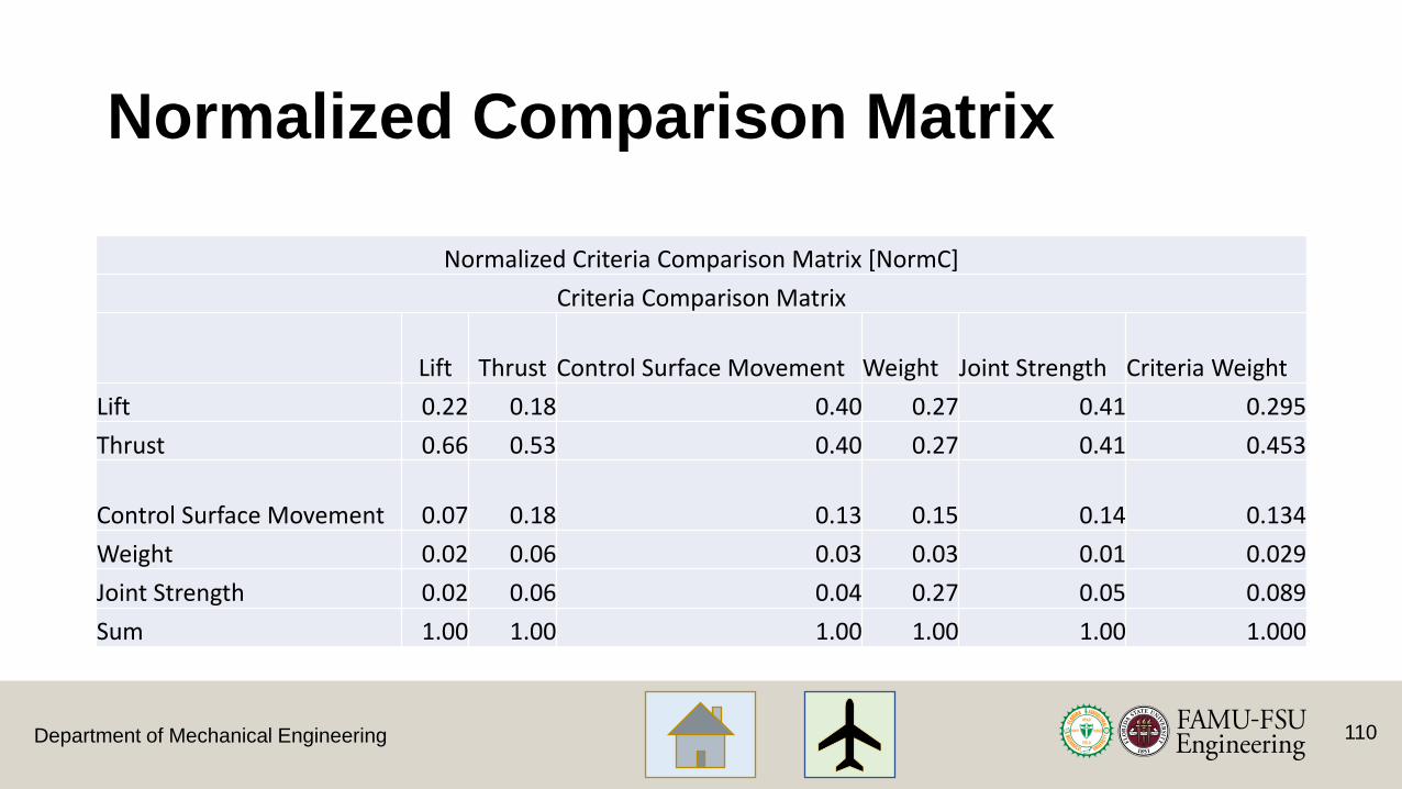
Normalized Comparison Matrix
110
Normalized Criteria Comparison Matrix [NormC]
Criteria Comparison Matrix
Lift Thrust Control Surface Movement Weight Joint Strength Criteria Weight
Lift 0.22 0.18 0.40 0.27 0.41 0.295
Thrust 0.66 0.53 0.40 0.27 0.41 0.453
Control Surface Movement 0.07 0.18 0.13 0.15 0.14 0.134
Weight 0.02 0.06 0.03 0.03 0.01 0.029
Joint Strength 0.02 0.06 0.04 0.27 0.05 0.089
Sum 1.00 1.00 1.00 1.00 1.00 1.000
Department of Mechanical Engineering
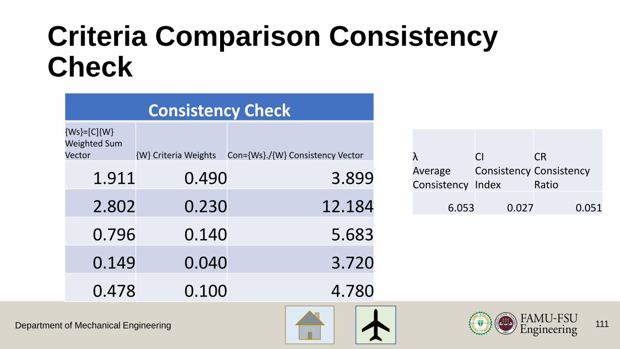
Criteria Comparison Consistency Check
λ Average Consistency
CI Consistency Index
CR Consistency Ratio
6.053 0.027 0.051
111
Consistency Check{Ws}=[C]{W} Weighted Sum Vector {W} Criteria Weights Con={Ws}./{W} Consistency Vector
1.911 0.490 3.899
2.802 0.230 12.184
0.796 0.140 5.683
0.149 0.040 3.720
0.478 0.100 4.780

Department of Mechanical Engineering
AHP – Lift Tables
112
Department of Mechanical Engineering
Lift Comparison Matrix
113
Lift Comparison
Concept 1 Concept 3 Concept 6
Concept 1 1.00 0.33 3.00
Concept 3 3.00 1.00 7.00
Concept 6 0.33 0.14 1.00
Sum 4.33 1.48 11.00
Department of Mechanical Engineering
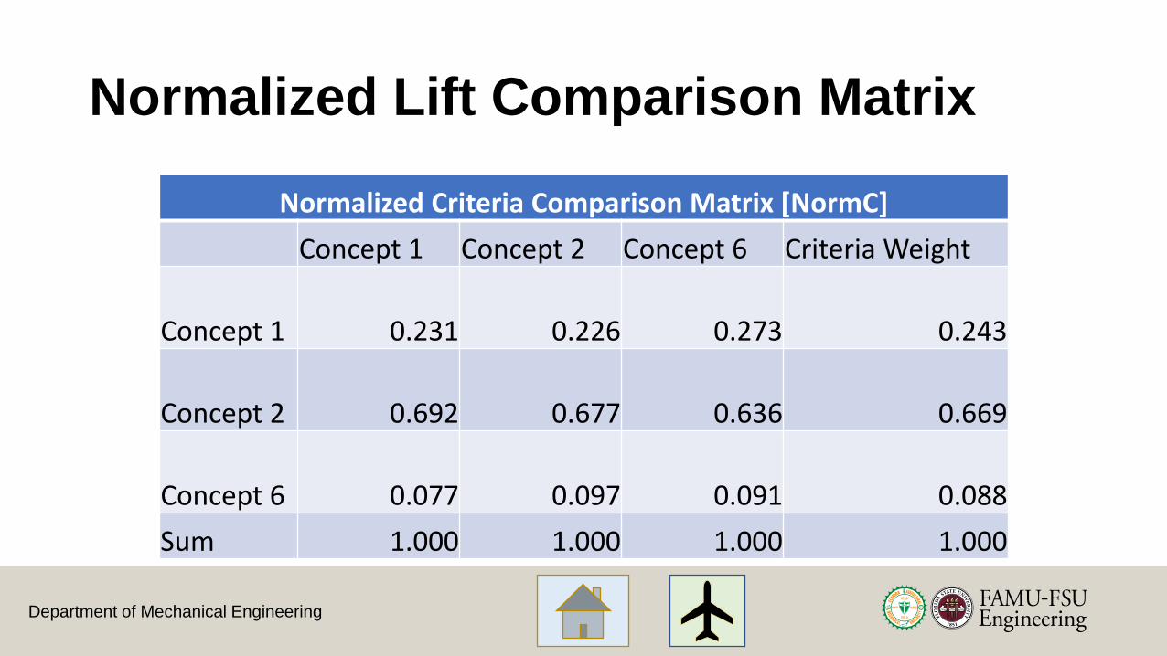
Normalized Lift Comparison Matrix
Normalized Criteria Comparison Matrix [NormC]
Concept 1 Concept 2 Concept 6 Criteria Weight
Concept 1 0.231 0.226 0.273 0.243
Concept 2 0.692 0.677 0.636 0.669
Concept 6 0.077 0.097 0.091 0.088
Sum 1.000 1.000 1.000 1.000

Department of Mechanical Engineering
Lift Consistency Check
115
Consistency Check 1{Ws}=[C]{W} Weighted Sum Vector
{W} Criteria Weights
Con={Ws}./{W} Consistency Vector
0.731 0.243 3.005
2.015 0.669 3.014
0.265 0.088 3.002
λ Average Consistency
CI Consistency Index
CR Consistency Ratio
3.00703 0.00352 0.00676

Department of Mechanical Engineering
AHP – Thrust Tables
116
Department of Mechanical Engineering
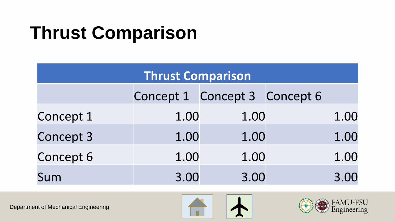
Thrust Comparison
Thrust Comparison
Concept 1 Concept 3 Concept 6
Concept 1 1.00 1.00 1.00
Concept 3 1.00 1.00 1.00
Concept 6 1.00 1.00 1.00
Sum 3.00 3.00 3.00

Department of Mechanical Engineering
Normalized Thrust Comparison Matrix
118
Normalized Criteria Comparison Matrix [NormC]
Concept 1 Concept 2 Concept 6 Criteria Weight
Concept 1 0.333 0.333 0.333 0.333
Concept 2 0.333 0.333 0.333 0.333
Concept 6 0.333 0.333 0.333 0.333
Sum 1.000 1.000 1.000 1.000

Department of Mechanical Engineering
Thrust Consistency Check
λ Average Consistency
CI Consistency Index
CR Consistency Ratio
3.00000 0.00000 0.00000
119
Consistency Check 2
{Ws}=[C]{W} Weighted Sum Vector
{W} Criteria Weights
Con={Ws}./{W} Consistency Vector
1.000 0.333 3.000
1.000 0.333 3.000
1.000 0.333 3.000

Department of Mechanical Engineering
AHP – Control Surface Movement Tables
120

Department of Mechanical Engineering
Control Surface Comparison Matrix
121
Control Surface Movement Comparison
Concept 1 Concept 3 Concept 6
Concept 1 1.00 3.00 0.20
Concept 3 0.33 1.00 0.20
Concept 6 3.00 5.00 1.00
Sum 4.33 9.00 1.40

Department of Mechanical Engineering
Normalized Control Surface Comparison Matrix
122
Normalized Criteria Comparison Matrix [NormC]
Concept 1 Concept 2 Concept 6 Criteria Weight
Concept 1 0.231 0.333 0.143 0.236
Concept 2 0.077 0.111 0.143 0.110
Concept 6 0.692 0.556 0.714 0.654
Sum 1.000 1.000 1.000 1.000

Department of Mechanical Engineering
Control Surface Consistency Check
λ Average Consistency
CI Consistency Index
CR Consistency Ratio
2.92716 -0.03642 -0.07004
123
Consistency Check 3
{Ws}=[C]{W} Weighted Sum Vector
{W} Criteria Weights
Con={Ws}./{W} Consistency Vector
0.697 0.236 2.959
0.320 0.110 2.898
1.912 0.654 2.924

Department of Mechanical Engineering
AHP – Weight Tables
124

Department of Mechanical Engineering
Weight Comparison Matrix
125
Weight Comparison
Concept 1 Concept 3 Concept 6
Concept 1 1.00 0.33 3.00
Concept 3 3.00 1.00 5.00
Concept 6 0.33 0.20 1.00
Sum 4.33 1.53 9.00
Department of Mechanical Engineering
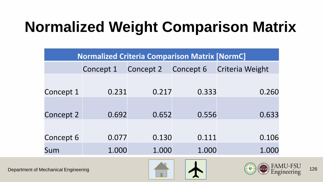
Normalized Weight Comparison Matrix
126
Normalized Criteria Comparison Matrix [NormC]
Concept 1 Concept 2 Concept 6 Criteria Weight
Concept 1 0.231 0.217 0.333 0.260
Concept 2 0.692 0.652 0.556 0.633
Concept 6 0.077 0.130 0.111 0.106
Sum 1.000 1.000 1.000 1.000

Department of Mechanical Engineering
Weight Consistency Check
λ Average Consistency
CI Consistency Index
CR Consistency Ratio
3.03871 0.01936 0.03723
127
Consistency Check 4
{Ws}=[C]{W} Weighted Sum Vector
{W} Criteria Weights
Con={Ws}./{W} Consistency Vector
0.790 0.260 3.033
1.946 0.633 3.072
0.320 0.106 3.011
Department of Mechanical Engineering
AHP – Joint Strength TablesFrom Team 508
128
Department of Mechanical Engineering
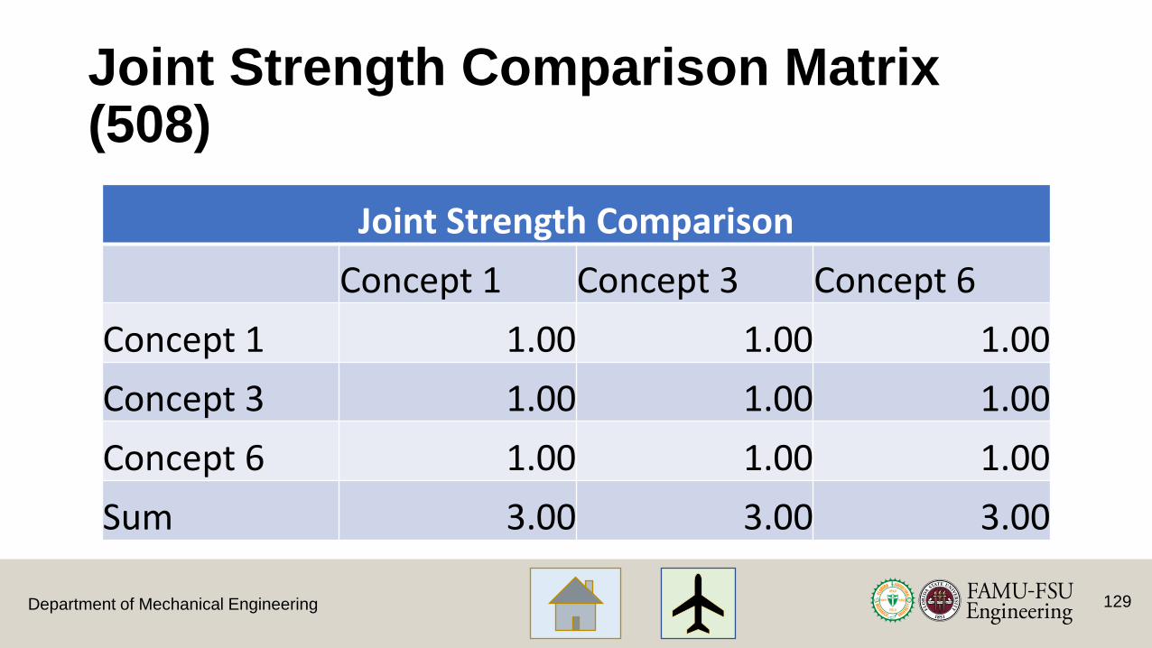
Joint Strength Comparison Matrix (508)
129
Joint Strength Comparison
Concept 1 Concept 3 Concept 6
Concept 1 1.00 1.00 1.00
Concept 3 1.00 1.00 1.00
Concept 6 1.00 1.00 1.00
Sum 3.00 3.00 3.00

Department of Mechanical Engineering
Normalized Joint Comparison Matrix (508)
130
Normalized Criteria Comparison Matrix [NormC]
Concept 1 Concept 2 Concept 6 Criteria Weight
Concept 1 0.333 0.333 0.333 0.333
Concept 2 0.333 0.333 0.333 0.333
Concept 6 0.333 0.333 0.333 0.333
Sum 1.000 1.000 1.000 1.000

Department of Mechanical Engineering
Joint Strength Consistency Check(508)
λ Average Consistency
CI Consistency Index
CR Consistency Ratio
3.00000 0.00000 0.00000
131
Consistency Check 5
{Ws}=[C]{W} Weighted Sum Vector
{W} Criteria Weights
Con={Ws}./{W} Consistency Vector
1.000 0.333 3.000
1.000 0.333 3.000
1.000 0.333 3.000

Department of Mechanical Engineering
Final Rating
132
Department of Mechanical Engineering
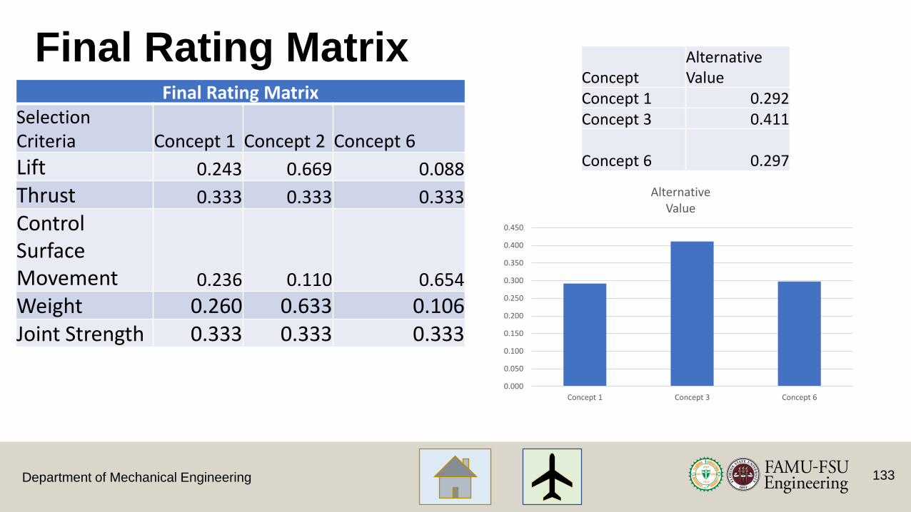
Final Rating MatrixConcept
Alternative Value
Concept 1 0.292Concept 3 0.411
Concept 6 0.297
133
Final Rating MatrixSelection Criteria Concept 1 Concept 2 Concept 6
Lift 0.243 0.669 0.088
Thrust 0.333 0.333 0.333
Control Surface Movement 0.236 0.110 0.654
Weight 0.260 0.633 0.106Joint Strength 0.333 0.333 0.333
0.000
0.050
0.100
0.150
0.200
0.250
0.300
0.350
0.400
0.450
Concept 1 Concept 3 Concept 6
Alternative Value

Department of Mechanical Engineering
Backup Slides – Winter Break
134
Department of Mechanical Engineering
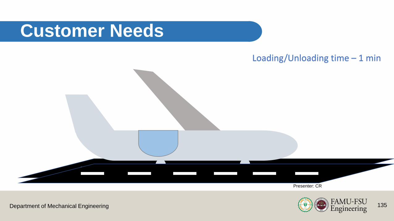
Customer Needs
Loading/Unloading time – 1 min
Presenter: CR
135

Department of Mechanical Engineering
Current Work – Fluid Analysis Eppler 423 Airfoil
Presenter: AM
136
Department of Mechanical Engineering
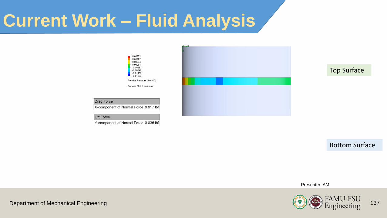
Current Work – Fluid Analysis
Presenter: AM
137
Top Surface
Bottom Surface

138Department of Mechanical Engineering
Initial CFD – Shell Properties
Presenter: AM

139Department of Mechanical Engineering
Fuselage Based on Lockheed X
Presenter: AM

140Department of Mechanical Engineering
Dorsal Fin
Presenter: AM
Dolphin Dorsal FinBiomimicry in Aircrafts
Recommended